EP3708896A1 - Gas-tank-system, verfahren zum betreiben des gas-tank-systems und zug mit gas-tank-system - Google Patents
Gas-tank-system, verfahren zum betreiben des gas-tank-systems und zug mit gas-tank-system Download PDFInfo
- Publication number
- EP3708896A1 EP3708896A1 EP20160706.6A EP20160706A EP3708896A1 EP 3708896 A1 EP3708896 A1 EP 3708896A1 EP 20160706 A EP20160706 A EP 20160706A EP 3708896 A1 EP3708896 A1 EP 3708896A1
- Authority
- EP
- European Patent Office
- Prior art keywords
- gas
- tank system
- channel
- outlet
- gas tank
- Prior art date
- Legal status (The legal status is an assumption and is not a legal conclusion. Google has not performed a legal analysis and makes no representation as to the accuracy of the status listed.)
- Granted
Links
Images

Classifications
-
- F—MECHANICAL ENGINEERING; LIGHTING; HEATING; WEAPONS; BLASTING
- F17—STORING OR DISTRIBUTING GASES OR LIQUIDS
- F17C—VESSELS FOR CONTAINING OR STORING COMPRESSED, LIQUEFIED OR SOLIDIFIED GASES; FIXED-CAPACITY GAS-HOLDERS; FILLING VESSELS WITH, OR DISCHARGING FROM VESSELS, COMPRESSED, LIQUEFIED, OR SOLIDIFIED GASES
- F17C1/00—Pressure vessels, e.g. gas cylinder, gas tank, replaceable cartridge
- F17C1/02—Pressure vessels, e.g. gas cylinder, gas tank, replaceable cartridge involving reinforcing arrangements
- F17C1/04—Protecting sheathings
- F17C1/06—Protecting sheathings built-up from wound-on bands or filamentary material, e.g. wires
-
- F—MECHANICAL ENGINEERING; LIGHTING; HEATING; WEAPONS; BLASTING
- F17—STORING OR DISTRIBUTING GASES OR LIQUIDS
- F17C—VESSELS FOR CONTAINING OR STORING COMPRESSED, LIQUEFIED OR SOLIDIFIED GASES; FIXED-CAPACITY GAS-HOLDERS; FILLING VESSELS WITH, OR DISCHARGING FROM VESSELS, COMPRESSED, LIQUEFIED, OR SOLIDIFIED GASES
- F17C2201/00—Vessel construction, in particular geometry, arrangement or size
- F17C2201/01—Shape
- F17C2201/0104—Shape cylindrical
- F17C2201/0109—Shape cylindrical with exteriorly curved end-piece
-
- F—MECHANICAL ENGINEERING; LIGHTING; HEATING; WEAPONS; BLASTING
- F17—STORING OR DISTRIBUTING GASES OR LIQUIDS
- F17C—VESSELS FOR CONTAINING OR STORING COMPRESSED, LIQUEFIED OR SOLIDIFIED GASES; FIXED-CAPACITY GAS-HOLDERS; FILLING VESSELS WITH, OR DISCHARGING FROM VESSELS, COMPRESSED, LIQUEFIED, OR SOLIDIFIED GASES
- F17C2201/00—Vessel construction, in particular geometry, arrangement or size
- F17C2201/01—Shape
- F17C2201/0147—Shape complex
- F17C2201/0166—Shape complex divided in several chambers
-
- F—MECHANICAL ENGINEERING; LIGHTING; HEATING; WEAPONS; BLASTING
- F17—STORING OR DISTRIBUTING GASES OR LIQUIDS
- F17C—VESSELS FOR CONTAINING OR STORING COMPRESSED, LIQUEFIED OR SOLIDIFIED GASES; FIXED-CAPACITY GAS-HOLDERS; FILLING VESSELS WITH, OR DISCHARGING FROM VESSELS, COMPRESSED, LIQUEFIED, OR SOLIDIFIED GASES
- F17C2201/00—Vessel construction, in particular geometry, arrangement or size
- F17C2201/01—Shape
- F17C2201/0147—Shape complex
- F17C2201/0171—Shape complex comprising a communication hole between chambers
-
- F—MECHANICAL ENGINEERING; LIGHTING; HEATING; WEAPONS; BLASTING
- F17—STORING OR DISTRIBUTING GASES OR LIQUIDS
- F17C—VESSELS FOR CONTAINING OR STORING COMPRESSED, LIQUEFIED OR SOLIDIFIED GASES; FIXED-CAPACITY GAS-HOLDERS; FILLING VESSELS WITH, OR DISCHARGING FROM VESSELS, COMPRESSED, LIQUEFIED, OR SOLIDIFIED GASES
- F17C2201/00—Vessel construction, in particular geometry, arrangement or size
- F17C2201/03—Orientation
- F17C2201/035—Orientation with substantially horizontal main axis
-
- F—MECHANICAL ENGINEERING; LIGHTING; HEATING; WEAPONS; BLASTING
- F17—STORING OR DISTRIBUTING GASES OR LIQUIDS
- F17C—VESSELS FOR CONTAINING OR STORING COMPRESSED, LIQUEFIED OR SOLIDIFIED GASES; FIXED-CAPACITY GAS-HOLDERS; FILLING VESSELS WITH, OR DISCHARGING FROM VESSELS, COMPRESSED, LIQUEFIED, OR SOLIDIFIED GASES
- F17C2201/00—Vessel construction, in particular geometry, arrangement or size
- F17C2201/05—Size
- F17C2201/054—Size medium (>1 m3)
-
- F—MECHANICAL ENGINEERING; LIGHTING; HEATING; WEAPONS; BLASTING
- F17—STORING OR DISTRIBUTING GASES OR LIQUIDS
- F17C—VESSELS FOR CONTAINING OR STORING COMPRESSED, LIQUEFIED OR SOLIDIFIED GASES; FIXED-CAPACITY GAS-HOLDERS; FILLING VESSELS WITH, OR DISCHARGING FROM VESSELS, COMPRESSED, LIQUEFIED, OR SOLIDIFIED GASES
- F17C2203/00—Vessel construction, in particular walls or details thereof
- F17C2203/06—Materials for walls or layers thereof; Properties or structures of walls or their materials
- F17C2203/0602—Wall structures; Special features thereof
- F17C2203/0604—Liners
-
- F—MECHANICAL ENGINEERING; LIGHTING; HEATING; WEAPONS; BLASTING
- F17—STORING OR DISTRIBUTING GASES OR LIQUIDS
- F17C—VESSELS FOR CONTAINING OR STORING COMPRESSED, LIQUEFIED OR SOLIDIFIED GASES; FIXED-CAPACITY GAS-HOLDERS; FILLING VESSELS WITH, OR DISCHARGING FROM VESSELS, COMPRESSED, LIQUEFIED, OR SOLIDIFIED GASES
- F17C2203/00—Vessel construction, in particular walls or details thereof
- F17C2203/06—Materials for walls or layers thereof; Properties or structures of walls or their materials
- F17C2203/0602—Wall structures; Special features thereof
- F17C2203/0612—Wall structures
- F17C2203/0626—Multiple walls
- F17C2203/0629—Two walls
-
- F—MECHANICAL ENGINEERING; LIGHTING; HEATING; WEAPONS; BLASTING
- F17—STORING OR DISTRIBUTING GASES OR LIQUIDS
- F17C—VESSELS FOR CONTAINING OR STORING COMPRESSED, LIQUEFIED OR SOLIDIFIED GASES; FIXED-CAPACITY GAS-HOLDERS; FILLING VESSELS WITH, OR DISCHARGING FROM VESSELS, COMPRESSED, LIQUEFIED, OR SOLIDIFIED GASES
- F17C2203/00—Vessel construction, in particular walls or details thereof
- F17C2203/06—Materials for walls or layers thereof; Properties or structures of walls or their materials
- F17C2203/0602—Wall structures; Special features thereof
- F17C2203/0612—Wall structures
- F17C2203/0626—Multiple walls
- F17C2203/0631—Three or more walls
-
- F—MECHANICAL ENGINEERING; LIGHTING; HEATING; WEAPONS; BLASTING
- F17—STORING OR DISTRIBUTING GASES OR LIQUIDS
- F17C—VESSELS FOR CONTAINING OR STORING COMPRESSED, LIQUEFIED OR SOLIDIFIED GASES; FIXED-CAPACITY GAS-HOLDERS; FILLING VESSELS WITH, OR DISCHARGING FROM VESSELS, COMPRESSED, LIQUEFIED, OR SOLIDIFIED GASES
- F17C2203/00—Vessel construction, in particular walls or details thereof
- F17C2203/06—Materials for walls or layers thereof; Properties or structures of walls or their materials
- F17C2203/0634—Materials for walls or layers thereof
- F17C2203/0658—Synthetics
- F17C2203/066—Plastics
-
- F—MECHANICAL ENGINEERING; LIGHTING; HEATING; WEAPONS; BLASTING
- F17—STORING OR DISTRIBUTING GASES OR LIQUIDS
- F17C—VESSELS FOR CONTAINING OR STORING COMPRESSED, LIQUEFIED OR SOLIDIFIED GASES; FIXED-CAPACITY GAS-HOLDERS; FILLING VESSELS WITH, OR DISCHARGING FROM VESSELS, COMPRESSED, LIQUEFIED, OR SOLIDIFIED GASES
- F17C2203/00—Vessel construction, in particular walls or details thereof
- F17C2203/06—Materials for walls or layers thereof; Properties or structures of walls or their materials
- F17C2203/0634—Materials for walls or layers thereof
- F17C2203/0658—Synthetics
- F17C2203/0663—Synthetics in form of fibers or filaments
-
- F—MECHANICAL ENGINEERING; LIGHTING; HEATING; WEAPONS; BLASTING
- F17—STORING OR DISTRIBUTING GASES OR LIQUIDS
- F17C—VESSELS FOR CONTAINING OR STORING COMPRESSED, LIQUEFIED OR SOLIDIFIED GASES; FIXED-CAPACITY GAS-HOLDERS; FILLING VESSELS WITH, OR DISCHARGING FROM VESSELS, COMPRESSED, LIQUEFIED, OR SOLIDIFIED GASES
- F17C2203/00—Vessel construction, in particular walls or details thereof
- F17C2203/06—Materials for walls or layers thereof; Properties or structures of walls or their materials
- F17C2203/0634—Materials for walls or layers thereof
- F17C2203/0658—Synthetics
- F17C2203/0675—Synthetics with details of composition
-
- F—MECHANICAL ENGINEERING; LIGHTING; HEATING; WEAPONS; BLASTING
- F17—STORING OR DISTRIBUTING GASES OR LIQUIDS
- F17C—VESSELS FOR CONTAINING OR STORING COMPRESSED, LIQUEFIED OR SOLIDIFIED GASES; FIXED-CAPACITY GAS-HOLDERS; FILLING VESSELS WITH, OR DISCHARGING FROM VESSELS, COMPRESSED, LIQUEFIED, OR SOLIDIFIED GASES
- F17C2203/00—Vessel construction, in particular walls or details thereof
- F17C2203/06—Materials for walls or layers thereof; Properties or structures of walls or their materials
- F17C2203/068—Special properties of materials for vessel walls
- F17C2203/0682—Special properties of materials for vessel walls with liquid or gas layer
-
- F—MECHANICAL ENGINEERING; LIGHTING; HEATING; WEAPONS; BLASTING
- F17—STORING OR DISTRIBUTING GASES OR LIQUIDS
- F17C—VESSELS FOR CONTAINING OR STORING COMPRESSED, LIQUEFIED OR SOLIDIFIED GASES; FIXED-CAPACITY GAS-HOLDERS; FILLING VESSELS WITH, OR DISCHARGING FROM VESSELS, COMPRESSED, LIQUEFIED, OR SOLIDIFIED GASES
- F17C2205/00—Vessel construction, in particular mounting arrangements, attachments or identifications means
- F17C2205/01—Mounting arrangements
- F17C2205/0123—Mounting arrangements characterised by number of vessels
- F17C2205/013—Two or more vessels
- F17C2205/0149—Vessel mounted inside another one
-
- F—MECHANICAL ENGINEERING; LIGHTING; HEATING; WEAPONS; BLASTING
- F17—STORING OR DISTRIBUTING GASES OR LIQUIDS
- F17C—VESSELS FOR CONTAINING OR STORING COMPRESSED, LIQUEFIED OR SOLIDIFIED GASES; FIXED-CAPACITY GAS-HOLDERS; FILLING VESSELS WITH, OR DISCHARGING FROM VESSELS, COMPRESSED, LIQUEFIED, OR SOLIDIFIED GASES
- F17C2205/00—Vessel construction, in particular mounting arrangements, attachments or identifications means
- F17C2205/03—Fluid connections, filters, valves, closure means or other attachments
- F17C2205/0302—Fittings, valves, filters, or components in connection with the gas storage device
- F17C2205/0323—Valves
- F17C2205/0332—Safety valves or pressure relief valves
-
- F—MECHANICAL ENGINEERING; LIGHTING; HEATING; WEAPONS; BLASTING
- F17—STORING OR DISTRIBUTING GASES OR LIQUIDS
- F17C—VESSELS FOR CONTAINING OR STORING COMPRESSED, LIQUEFIED OR SOLIDIFIED GASES; FIXED-CAPACITY GAS-HOLDERS; FILLING VESSELS WITH, OR DISCHARGING FROM VESSELS, COMPRESSED, LIQUEFIED, OR SOLIDIFIED GASES
- F17C2221/00—Handled fluid, in particular type of fluid
- F17C2221/01—Pure fluids
- F17C2221/012—Hydrogen
-
- F—MECHANICAL ENGINEERING; LIGHTING; HEATING; WEAPONS; BLASTING
- F17—STORING OR DISTRIBUTING GASES OR LIQUIDS
- F17C—VESSELS FOR CONTAINING OR STORING COMPRESSED, LIQUEFIED OR SOLIDIFIED GASES; FIXED-CAPACITY GAS-HOLDERS; FILLING VESSELS WITH, OR DISCHARGING FROM VESSELS, COMPRESSED, LIQUEFIED, OR SOLIDIFIED GASES
- F17C2221/00—Handled fluid, in particular type of fluid
- F17C2221/03—Mixtures
- F17C2221/032—Hydrocarbons
- F17C2221/033—Methane, e.g. natural gas, CNG, LNG, GNL, GNC, PLNG
-
- F—MECHANICAL ENGINEERING; LIGHTING; HEATING; WEAPONS; BLASTING
- F17—STORING OR DISTRIBUTING GASES OR LIQUIDS
- F17C—VESSELS FOR CONTAINING OR STORING COMPRESSED, LIQUEFIED OR SOLIDIFIED GASES; FIXED-CAPACITY GAS-HOLDERS; FILLING VESSELS WITH, OR DISCHARGING FROM VESSELS, COMPRESSED, LIQUEFIED, OR SOLIDIFIED GASES
- F17C2223/00—Handled fluid before transfer, i.e. state of fluid when stored in the vessel or before transfer from the vessel
- F17C2223/01—Handled fluid before transfer, i.e. state of fluid when stored in the vessel or before transfer from the vessel characterised by the phase
- F17C2223/0107—Single phase
- F17C2223/0123—Single phase gaseous, e.g. CNG, GNC
-
- F—MECHANICAL ENGINEERING; LIGHTING; HEATING; WEAPONS; BLASTING
- F17—STORING OR DISTRIBUTING GASES OR LIQUIDS
- F17C—VESSELS FOR CONTAINING OR STORING COMPRESSED, LIQUEFIED OR SOLIDIFIED GASES; FIXED-CAPACITY GAS-HOLDERS; FILLING VESSELS WITH, OR DISCHARGING FROM VESSELS, COMPRESSED, LIQUEFIED, OR SOLIDIFIED GASES
- F17C2223/00—Handled fluid before transfer, i.e. state of fluid when stored in the vessel or before transfer from the vessel
- F17C2223/03—Handled fluid before transfer, i.e. state of fluid when stored in the vessel or before transfer from the vessel characterised by the pressure level
- F17C2223/036—Very high pressure (>80 bar)
-
- F—MECHANICAL ENGINEERING; LIGHTING; HEATING; WEAPONS; BLASTING
- F17—STORING OR DISTRIBUTING GASES OR LIQUIDS
- F17C—VESSELS FOR CONTAINING OR STORING COMPRESSED, LIQUEFIED OR SOLIDIFIED GASES; FIXED-CAPACITY GAS-HOLDERS; FILLING VESSELS WITH, OR DISCHARGING FROM VESSELS, COMPRESSED, LIQUEFIED, OR SOLIDIFIED GASES
- F17C2225/00—Handled fluid after transfer, i.e. state of fluid after transfer from the vessel
- F17C2225/01—Handled fluid after transfer, i.e. state of fluid after transfer from the vessel characterised by the phase
- F17C2225/0107—Single phase
- F17C2225/0123—Single phase gaseous, e.g. CNG, GNC
-
- F—MECHANICAL ENGINEERING; LIGHTING; HEATING; WEAPONS; BLASTING
- F17—STORING OR DISTRIBUTING GASES OR LIQUIDS
- F17C—VESSELS FOR CONTAINING OR STORING COMPRESSED, LIQUEFIED OR SOLIDIFIED GASES; FIXED-CAPACITY GAS-HOLDERS; FILLING VESSELS WITH, OR DISCHARGING FROM VESSELS, COMPRESSED, LIQUEFIED, OR SOLIDIFIED GASES
- F17C2225/00—Handled fluid after transfer, i.e. state of fluid after transfer from the vessel
- F17C2225/03—Handled fluid after transfer, i.e. state of fluid after transfer from the vessel characterised by the pressure level
- F17C2225/036—Very high pressure, i.e. above 80 bars
-
- F—MECHANICAL ENGINEERING; LIGHTING; HEATING; WEAPONS; BLASTING
- F17—STORING OR DISTRIBUTING GASES OR LIQUIDS
- F17C—VESSELS FOR CONTAINING OR STORING COMPRESSED, LIQUEFIED OR SOLIDIFIED GASES; FIXED-CAPACITY GAS-HOLDERS; FILLING VESSELS WITH, OR DISCHARGING FROM VESSELS, COMPRESSED, LIQUEFIED, OR SOLIDIFIED GASES
- F17C2227/00—Transfer of fluids, i.e. method or means for transferring the fluid; Heat exchange with the fluid
- F17C2227/03—Heat exchange with the fluid
- F17C2227/0337—Heat exchange with the fluid by cooling
-
- F—MECHANICAL ENGINEERING; LIGHTING; HEATING; WEAPONS; BLASTING
- F17—STORING OR DISTRIBUTING GASES OR LIQUIDS
- F17C—VESSELS FOR CONTAINING OR STORING COMPRESSED, LIQUEFIED OR SOLIDIFIED GASES; FIXED-CAPACITY GAS-HOLDERS; FILLING VESSELS WITH, OR DISCHARGING FROM VESSELS, COMPRESSED, LIQUEFIED, OR SOLIDIFIED GASES
- F17C2227/00—Transfer of fluids, i.e. method or means for transferring the fluid; Heat exchange with the fluid
- F17C2227/03—Heat exchange with the fluid
- F17C2227/0337—Heat exchange with the fluid by cooling
- F17C2227/0339—Heat exchange with the fluid by cooling using the same fluid
-
- F—MECHANICAL ENGINEERING; LIGHTING; HEATING; WEAPONS; BLASTING
- F17—STORING OR DISTRIBUTING GASES OR LIQUIDS
- F17C—VESSELS FOR CONTAINING OR STORING COMPRESSED, LIQUEFIED OR SOLIDIFIED GASES; FIXED-CAPACITY GAS-HOLDERS; FILLING VESSELS WITH, OR DISCHARGING FROM VESSELS, COMPRESSED, LIQUEFIED, OR SOLIDIFIED GASES
- F17C2227/00—Transfer of fluids, i.e. method or means for transferring the fluid; Heat exchange with the fluid
- F17C2227/03—Heat exchange with the fluid
- F17C2227/0367—Localisation of heat exchange
- F17C2227/0369—Localisation of heat exchange in or on a vessel
- F17C2227/0372—Localisation of heat exchange in or on a vessel in the gas
-
- F—MECHANICAL ENGINEERING; LIGHTING; HEATING; WEAPONS; BLASTING
- F17—STORING OR DISTRIBUTING GASES OR LIQUIDS
- F17C—VESSELS FOR CONTAINING OR STORING COMPRESSED, LIQUEFIED OR SOLIDIFIED GASES; FIXED-CAPACITY GAS-HOLDERS; FILLING VESSELS WITH, OR DISCHARGING FROM VESSELS, COMPRESSED, LIQUEFIED, OR SOLIDIFIED GASES
- F17C2227/00—Transfer of fluids, i.e. method or means for transferring the fluid; Heat exchange with the fluid
- F17C2227/03—Heat exchange with the fluid
- F17C2227/0367—Localisation of heat exchange
- F17C2227/0369—Localisation of heat exchange in or on a vessel
- F17C2227/0376—Localisation of heat exchange in or on a vessel in wall contact
- F17C2227/0379—Localisation of heat exchange in or on a vessel in wall contact inside the vessel
-
- F—MECHANICAL ENGINEERING; LIGHTING; HEATING; WEAPONS; BLASTING
- F17—STORING OR DISTRIBUTING GASES OR LIQUIDS
- F17C—VESSELS FOR CONTAINING OR STORING COMPRESSED, LIQUEFIED OR SOLIDIFIED GASES; FIXED-CAPACITY GAS-HOLDERS; FILLING VESSELS WITH, OR DISCHARGING FROM VESSELS, COMPRESSED, LIQUEFIED, OR SOLIDIFIED GASES
- F17C2227/00—Transfer of fluids, i.e. method or means for transferring the fluid; Heat exchange with the fluid
- F17C2227/03—Heat exchange with the fluid
- F17C2227/0367—Localisation of heat exchange
- F17C2227/0369—Localisation of heat exchange in or on a vessel
- F17C2227/0376—Localisation of heat exchange in or on a vessel in wall contact
- F17C2227/0381—Localisation of heat exchange in or on a vessel in wall contact integrated in the wall
-
- F—MECHANICAL ENGINEERING; LIGHTING; HEATING; WEAPONS; BLASTING
- F17—STORING OR DISTRIBUTING GASES OR LIQUIDS
- F17C—VESSELS FOR CONTAINING OR STORING COMPRESSED, LIQUEFIED OR SOLIDIFIED GASES; FIXED-CAPACITY GAS-HOLDERS; FILLING VESSELS WITH, OR DISCHARGING FROM VESSELS, COMPRESSED, LIQUEFIED, OR SOLIDIFIED GASES
- F17C2250/00—Accessories; Control means; Indicating, measuring or monitoring of parameters
- F17C2250/04—Indicating or measuring of parameters as input values
- F17C2250/0404—Parameters indicated or measured
- F17C2250/0439—Temperature
-
- F—MECHANICAL ENGINEERING; LIGHTING; HEATING; WEAPONS; BLASTING
- F17—STORING OR DISTRIBUTING GASES OR LIQUIDS
- F17C—VESSELS FOR CONTAINING OR STORING COMPRESSED, LIQUEFIED OR SOLIDIFIED GASES; FIXED-CAPACITY GAS-HOLDERS; FILLING VESSELS WITH, OR DISCHARGING FROM VESSELS, COMPRESSED, LIQUEFIED, OR SOLIDIFIED GASES
- F17C2250/00—Accessories; Control means; Indicating, measuring or monitoring of parameters
- F17C2250/06—Controlling or regulating of parameters as output values
- F17C2250/0605—Parameters
- F17C2250/0636—Flow or movement of content
-
- F—MECHANICAL ENGINEERING; LIGHTING; HEATING; WEAPONS; BLASTING
- F17—STORING OR DISTRIBUTING GASES OR LIQUIDS
- F17C—VESSELS FOR CONTAINING OR STORING COMPRESSED, LIQUEFIED OR SOLIDIFIED GASES; FIXED-CAPACITY GAS-HOLDERS; FILLING VESSELS WITH, OR DISCHARGING FROM VESSELS, COMPRESSED, LIQUEFIED, OR SOLIDIFIED GASES
- F17C2260/00—Purposes of gas storage and gas handling
- F17C2260/02—Improving properties related to fluid or fluid transfer
- F17C2260/025—Reducing transfer time
-
- F—MECHANICAL ENGINEERING; LIGHTING; HEATING; WEAPONS; BLASTING
- F17—STORING OR DISTRIBUTING GASES OR LIQUIDS
- F17C—VESSELS FOR CONTAINING OR STORING COMPRESSED, LIQUEFIED OR SOLIDIFIED GASES; FIXED-CAPACITY GAS-HOLDERS; FILLING VESSELS WITH, OR DISCHARGING FROM VESSELS, COMPRESSED, LIQUEFIED, OR SOLIDIFIED GASES
- F17C2270/00—Applications
- F17C2270/01—Applications for fluid transport or storage
- F17C2270/0165—Applications for fluid transport or storage on the road
- F17C2270/0168—Applications for fluid transport or storage on the road by vehicles
- F17C2270/0173—Railways
-
- Y—GENERAL TAGGING OF NEW TECHNOLOGICAL DEVELOPMENTS; GENERAL TAGGING OF CROSS-SECTIONAL TECHNOLOGIES SPANNING OVER SEVERAL SECTIONS OF THE IPC; TECHNICAL SUBJECTS COVERED BY FORMER USPC CROSS-REFERENCE ART COLLECTIONS [XRACs] AND DIGESTS
- Y02—TECHNOLOGIES OR APPLICATIONS FOR MITIGATION OR ADAPTATION AGAINST CLIMATE CHANGE
- Y02E—REDUCTION OF GREENHOUSE GAS [GHG] EMISSIONS, RELATED TO ENERGY GENERATION, TRANSMISSION OR DISTRIBUTION
- Y02E60/00—Enabling technologies; Technologies with a potential or indirect contribution to GHG emissions mitigation
- Y02E60/30—Hydrogen technology
- Y02E60/32—Hydrogen storage
Definitions
- the invention relates to a gas tank system, a method for operating a gas tank system and a train with a gas tank system.
- Hydrogen has the advantage of a high energy density compared to batteries in battery-operated trains, so that long ranges can be achieved.
- a particularly simple and therefore robust concept is based on gaseous compressed hydrogen.
- Typical pressure levels for a completely filled storage tank are 350 bar and 700 bar, whereby these pressures relate to a temperature of 15 ° C.
- There are now very suitable pressure tanks for gaseous hydrogen which can store hydrogen at 700 bar at 15 ° C and temporarily at 860 bar at 80 ° C. They are still very light and cycle stable.
- type IV tanks consist of an internal thin-walled plastic liner that is wrapped with resin-soaked carbon fibers.
- the liner ensures tightness and the carbon fibers ensure pressure stability.
- Hydrogen for example in a fuel cell, only needs to be relaxed. No complex procedural steps are therefore necessary.
- Another measure is to surround the pipes of the hydrogen system through which the fueling takes place with insulating material and thus to thermally insulate them. This prevents hydrogen that has been cooled by the introduction of heat from being reheated (e.g. to -40 ° C) and thus not reaching the inside of the tank at the lowest possible temperature as desired.
- the object is achieved according to the invention with a gas tank system according to claim 1, a method for operating a gas tank system according to claim 13 and a train according to claim 14 solved.
- the gas tank system according to the invention for use in a means of transportation comprises a gas-tight and pressure-stable outer shell. At least one inner heat-resistant shell is arranged therein, within which the gas can be stored.
- the gas tank system further comprises a channel, the channel being arranged between the outer and the inner shell and being delimited by the inner and the outer shell.
- the outer shell has an inlet for receiving the gas into the channel.
- the inner shell has a first outlet for guiding the gas from the channel into the inner shell.
- a cooling device is arranged at the first outlet of the channel.
- a gas tank system for use in a means of transport comprising a gas-tight outer shell, at least one inner heat-resistant shell arranged therein within which the gas can be stored, a channel, the channel being arranged between the outer and inner shell and is bounded by the inner and outer sheaths and wherein the outer sheath has an inlet for receiving the gas into the channel and the inner sheath has a first outlet for guiding the gas into the inner sheath, a cooling device being arranged at the first outlet of the channel is provided.
- the gas is fed into the inner shell through the channel. Due to the increasing pressure, the gas in the inner envelope heats up.
- the gas is then stored in the inner shell.
- the gas is then withdrawn through the first outlet, the gas being cooled in the cooling device.
- the gas is advantageously guided through the channel into the interior of the inner casing, in other words the interior of the tank. While the gas through the channel if there is a flow, the pressure does not increase. Therefore the temperature of the gas remains almost constant in the duct.
- the outer shell which is pressure-stable and gas-tight but sensitive to heat, is advantageously not exposed to high temperatures. The pressure and thus also the temperature only increases inside the inner shell. This comprises a heat-stable material. Rapid refueling can thus advantageously be carried out since the tank withstands higher temperatures due to the at least two outer shells. If the gas is removed from the interior of the inner shell after it has been stored, it is cooled on the cooling device during the removal.
- the gas tank is a hydrogen tank.
- hydrogen there are high requirements for hydrogen in terms of tightness and mechanical stability. These must also be observed when filling the tank and emptying the tank. Therefore, these properties must be retained even at increased pressure or high temperatures.
- the mechanical and tight outer shell is advantageously spatially separated from a heat-resistant inner shell. The entering hydrogen only heats up in the inner shell, as the pressure rises there. The hydrogen tank system is therefore suitable for fast and safe storage and emptying of the hydrogen storage tank.
- the pressure in the hydrogen tank is in particular essentially 350 bar or essentially 700 bar. Both pressures relate to a hydrogen temperature of 15 ° C.
- the inner heat-resistant shell is made from a first material comprising a fluoropolymer and / or a composite polymer.
- Heat-resistant means that the inner shell can withstand temperatures of up to 150 ° C, in particular 120 ° C or 100 ° C.
- the first material advantageously has the following features: It is temperature-resistant and has a low thermal conductivity. Hydrogen dissolves poorly in the first material so that it does not become brittle. The first material can be porous, since the tightness of the tank is achieved through the outer shell.
- the outer casing has a casing comprising plastic and a fiber material surrounding this casing.
- the casing is gas-tight.
- the fiber material surrounding the casing is mechanically stable.
- This structure is also known as the Tank IV type. These tanks are typically rotationally symmetrical, in particular essentially cylindrical.
- Type IV hydrogen storage tanks with the additional inner shell can advantageously be improved to the effect that rising temperatures inside the tank due to the pressure increase during the refueling process are kept away from the outer shell. This advantageously enables shorter refueling times.
- the outer casing has a second outlet. This can be used to remove the gas from the channel and / or to dissipate heat from the cooling device.
- the inlet into the channel is therefore not used to extract the gas.
- the inlet is then particularly advantageously thermally insulated. In this way, heat input from the surroundings into the tank is advantageously kept as low as possible.
- the second outlet is arranged opposite the inlet of the outer shell.
- This second outlet is designed in such a way that the best possible heat dissipation to the environment is possible. It can therefore be designed in particular in a solid construction.
- the second outlet particularly preferably comprises a thermally conductive material.
- the gas, especially hydrogen is typically used at pressures below the pressure level inside the tank. During the emptying of the tank, the gas then heats up, in particular the hydrogen, due to the Joule-Thomson effect, significant.
- a good heat dissipation advantageously means that the use of the hydrogen, in particular by a means of transport, can begin immediately after refueling, even if the temperatures in the tank can still be very high. It is particularly advantageous if the cooling device is then also connected to the second outlet and thus cools the first and the second outlet from the channel.
- the inlet and the first outlet are arranged opposite one another in the axial direction of the casings.
- the gas in particular the hydrogen
- flows into the channel through the inlet then flows to the opposite end of the channel and there flows through the first outlet into the inner shell.
- the temperature in the inner shell then rises due to the increase in pressure of the gas.
- the gas in the inner shell is advantageously cooled by means of the gas flowing in in the channel. This cooling effect is advantageously particularly pronounced due to the maximum length of the route through the channel. This means that very short refueling times can be achieved.
- the inlet and the second outlet are arranged on the same side of the outer and the inner shell.
- the first outlet with the cooling device is arranged opposite one another.
- the gas is led through the channel and the first outlet into the interior of the tank.
- the gas is then led out of the tank through the second outlet.
- the gas advantageously flows through the maximum channel length during a filling process.
- the cooling device is configured as a heat-conducting rod or as a heat pipe.
- the thermally conductive rod includes, in particular, copper.
- a copper rod advantageously has very good thermal conductivity.
- a heat pipe in particular with a filling comprising water, ethanol or a refrigerant, also transports the heat from the inside of the tank to the environment.
- the filling is in thermal contact with the interior of the tank, where it absorbs heat and evaporates.
- the heat pipe is in thermal contact with the environment, where it gives off heat and the filling condenses.
- the copper rod or the heat pipe are connected to the first and the second outlet.
- the gas can also advantageously be cooled when it is removed from the tank.
- the cooling device can be arranged in the second outlet, so that no additional opening is required in the outer shell in order to connect the cooling device to the environment. It is also conceivable that the second outlet is used exclusively for heat dissipation and the inlet is used for extraction from the channel.
- the cooling device has ribs. These ribs can be arranged on the outside of the cooling device to increase the surface area. They can also be arranged inside the cooling device as flow elements and to increase the surface area. These advantageously increase the efficiency of the cooling device and therefore also make shorter refueling times possible in particular.
- the gas tank system comprises at least two inner casings and at least two channels that are formed between the casings.
- Another advantageous embodiment relates to a hydrogen-powered train with the gas tank system according to the invention.
- the gas tank system according to the invention is advantageous both safely at high pressures and under mechanical stress, which is a prerequisite for use in a train. Furthermore, the construction of the tank with the inner and outer hulls allow the train to be refueled quickly while the tank remains heat-stable.
- a cooling device of the gas tank system in particular a heat-conducting component, is firmly connected to the train.
- the safe storage of the hydrogen can be guaranteed during fast refueling processes, especially in one train, since in particular the compression heat that arises at the beginning of the refueling process is led out of the gas tank system and, in particular, can be dissipated via a massive heat-conducting component of the train .
- Figure 1 shows a gas tank system 1 for storing a gas.
- the gas to be stored is hydrogen.
- the gas tank system is also suitable for storing methane and for operation in means of transport using natural gas (CNG).
- CNG natural gas
- the gas tank system 1 comprises a tank 30 with an outer shell 2 and an inner shell 3.
- a channel 5 is arranged between the outer shell 2 and the inner shell 3.
- the outer shell 2 has an inlet 6.
- An opening in the outer shell is referred to here as an inlet.
- a connection device 10 is arranged in this inlet 6.
- the inner shell 3 has a first outlet 7.
- An opening in the inner shell 3 is referred to here as the first outlet.
- a cooling device 4 is arranged at this first outlet 7.
- the cooling device protrudes into the surroundings via a second outlet 18.
- An opening in the outer shell 2 is referred to as the second outlet 18.
- the cooling device 4 comprises cooling fins 12.
- the connection device 10 is connected to a refueling line 13.
- the connection device 10 is also connected to a removal line 14.
- the outer shell 2 is typically a gas-tight shell.
- the inner shell 3 is typically a heat-stable shell.
- the outer shell 2 typically comprises resin-impregnated carbon fibers.
- the carbon fibers ensure pressure stability and the entire outer shell ensures tightness.
- the inner shell typically comprises a heat-resistant polymer, in particular a fluoropolymer and / or a composite polymer.
- a heat-resistant polymer in particular a fluoropolymer and / or a composite polymer.
- PPS polyphenylene sulfide
- PEEK polyether ether ketone
- PAI polyamide imide
- PSU polysulfone
- PPSU polyphenylene sulfone
- PES polyether sulfone
- other high-performance thermoplastics or fiber-reinforced polymers are also suitable. It is crucial that the plastics can withstand the maximum temperatures that occur without degradation.
- the hydrogen is fed through the refueling line 13 via the inlet 6 into the connection device 10 and from there distributed to the channels 5.
- the hydrogen is typically already cooled. It is therefore advantageous to thermally insulate the connection device 10.
- cooled hydrogen flows through the channels 5 via the first outlet 7 from the channel 5 into the interior of the inner shell 3.
- An advantage of the structure according to the exemplary embodiment is that cool hydrogen flows into the tank system through the channel 5 and has a cooling effect on the inner shell 3 and the outer shell 2. Overheating of the outer shell 2 by the cool hydrogen flowing through this channel 5 can thus be prevented.
- the hydrogen is withdrawn from the interior of the inner shell 3 in the opposite direction.
- the hydrogen therefore flows through the channels 5 back to the connection device 10, where it can be withdrawn from the tank through the extraction line 14.
- the hydrogen is cooled by means of the cooling device 4, in particular when it is withdrawn from the tank 30, in order to keep the temperature at the outer shell 2 low.
- the second outlet 18 is used here exclusively to remove heat from the tank 30.
- cooling device 4 at the first outlet 7 cools the hydrogen when the hydrogen is withdrawn from the interior of the tank 30 before it can come into contact with the outer shell 2.
- the cooling device 4 can be made small, since the removal of the hydrogen is carried out with low volume flows.
- volume of the channel 5 is also available as a tank volume, as a result of which almost the entire tank volume is available.
- FIG. 2 shows an alternative arrangement of the gas tank system 1.
- the arrangement of the extraction line 14 differs from the first embodiment.
- the extraction line 14 is arranged opposite the inlet 6 in the outer casing 2.
- Gas tank system 1 comprises a tank 30 with an outer shell 2 and an inner shell 3.
- a channel 5 is arranged between the outer shell 2 and the inner shell 3.
- the outer shell 2 has an inlet 6.
- An opening in the outer shell is referred to here as an inlet.
- a connection device 10 is arranged in this inlet 6.
- the connection device 10 is connected to a refueling line 13.
- the inner shell 3 has a first outlet 7. An opening in the inner shell 3 is referred to here as the first outlet.
- a cooling device 4 is arranged at this first outlet 7.
- the cooling device 4 is connected to the surroundings of the tank 30 via the second outlet 18.
- the cooling device 4 again comprises cooling fins 12.
- the cooling fins 12 are arranged within the channel 5. It is also conceivable, but not shown here, for the cooling ribs to be arranged both inside the channel 5 and outside the tank 30 in the vicinity.
- the cooling device 4 is firmly connected to a solid component 17 of the means of locomotion via a heat conduction device 16.
- the means of transport is in particular a train. Heat can therefore be advantageous over the massive Component can be derived.
- the cooling device 4 itself can thus be made very small.
- the tank 30 is filled in the same way as in the first exemplary embodiment: the hydrogen is fed into the connection device 10 via the refueling line 13 and from there passed through the channels 5 into the interior of the inner shell 3.
- the hydrogen is withdrawn from the tank 30, however, it is not returned through the entire channels 5, but instead is fed directly into the withdrawal line 14 via the second connection device 21.
- the hydrogen is cooled in channel 5 when it is withdrawn.
- the first connection device 10 and the second connection device 21 can advantageously include, in particular, filters, automatic shut-off valves and / or temperature-activated expansion valves. These are particularly necessary for tank containers longer than 1.65 m, since a bonfire test should be carried out here, which requires the sensors listed.
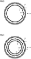
- Figure 3 shows a cross section of the tank 30.
- the outer shell 2 is surrounded by fiber material 20.
- the inner shell 3 is located inside the outer shell 2.
- the channels 5 are arranged between the inner shell 3 and the outer shell 2.
- the space between the two shells is divided by a plurality of channel webs 50, whereby a plurality of channels 5 are formed.
- the flow of hydrogen is thus advantageous when filling the tank 30, for the gas tank system of the first and second exemplary embodiments and when removing the hydrogen for the case of the first exemplary embodiment, influenced.
- the channel webs 50 can be arranged parallel to the main axis of the tank 30.
- the channel webs can in particular be straight, wave-shaped or jagged.
- FIG. 4 shows a further embodiment of the tank 30 in cross section.
- two inner shells 3 are arranged in the outer shell 2.
- the outer shell 2 is thus advantageously shielded from heat by a larger channel system.
- channel webs 50 are in the inner channel system analogous to the exemplary embodiment in FIG Figure 3 arranged.
- curved channel webs 51 are arranged in the outer channel system 52 . These extend helically around the central axis of the tank 30. In other words, they surround the center of the tank in a thread-like manner.
Landscapes
- Engineering & Computer Science (AREA)
- Mechanical Engineering (AREA)
- General Engineering & Computer Science (AREA)
- Filling Or Discharging Of Gas Storage Vessels (AREA)
Abstract
Description
- Die Erfindung betrifft ein Gas-Tank-System, ein Verfahren zum Betreiben eines Gas-Tank-Systems sowie einen Zug mit einem Gas-Tank-System.
- Ein großer Anteil der Zugstrecken in Europa ist nicht elektrifiziert. Diese Strecken werden heutzutage in der Regel mit Diesel-angetriebenen Zügen bedient. Nachteilig verursachen diese Züge Feinstaub, Stickoxide und lokale CO2-Emissionen und belasten daher die Umwelt.
- Züge, die mit Wasserstoff anstatt Diesel angetrieben werden, haben ein großes Potential den Zugverkehr umweltfreundlicher zu gestalten. Wasserstoff hat den Vorteil einer hohen Energiedichte verglichen mit Batterien in Batterie-betriebenen Zügen, so dass hohe Reichweiten erzielt werden können. Es gibt derzeit unterschiedliche Konzepte, was die Form angeht, in welcher der Wasserstoff an Bord der mobilen Anwendung gespeichert wird.
- Ein besonders einfaches und somit robustes Konzept beruht auf gasförmigem komprimiertem Wasserstoff. Typische Druckniveaus für einen vollständig gefüllten Speichertank sind 350 bar und 700 bar, wobei sich diese Drücke auf eine Temperatur von 15 °C beziehen. Für gasförmigen Wasserstoff gibt es inzwischen sehr gut geeignete Drucktanks, die Wasserstoff bei 700 bar bei 15 °C und zeitweise bei 860 bar bei 80 °C speichern können. Sie sind weiterhin sehr leicht und zyklenstabil.
- Es handelt sich hierbei um sogenannte Typ IV-Tanks. Sie bestehen aus einem innen liegenden dünnwandigen Kunststoff-Liner, der mit harzgetränkten Kohlefasern umwickelt ist. Der Liner sorgt für die Dichtheit und die Kohlefasern für die Druckstabilität. Für eine Nutzung des unter Druck gespeicherten Wasserstoffs z.B. in einer Brennstoffzelle muss er lediglich entspannt werden. Es sind also keine komplexen Verfahrensschritte nötig.
- Es gibt aus der Automobilindustrie bereits Normen für die Befüllung von Wasserstoff-angetriebenen Fahrzeugen. Diese beruhen im Wesentlichen darauf, dass bei dem Befüllvorgang der Druck des von der Tankstelle angebotenen Wasserstoffs kontinuierlich erhöht wird, um so kontinuierlich Wasserstoff in den Tank zu pressen. Wegen der Kompression von bereits vorhandenem Wasserstoff tritt eine starke Wärmetönung auf, so dass die Temperaturen im Tank schnell über 80 °C steigen könnten. Temperaturen über 85 °C sind in der Automobilnorm jedoch nicht für diese Tanks erlaubt, manche Fabrikate schränken den erlaubten Temperaturbereich sogar noch weiter ein. Die Temperaturerhöhung ist in der ersten Phase der Betankung besonders stark, so dass durch eine langsam gewählte Tankgeschwindigkeit eine Überhitzung des Tanks wegen einer Wärmeabgabe über das Tankmaterial an die Umgebung verhindert wird. Die langsamen Tankgeschwindigkeiten sind jedoch aus wirtschaftlicher Sicht ein großer Nachteil für den Betrieb von Wasserstoff-betriebenen Flotten, da sie unter ungünstigen Umständen durchaus im Bereich einer Stunde liegen können.
- Es gibt im Stand der Technik bereits Ansätze, die Tankzeit zu verkürzen. Beispielsweise kann gekühlter Wasserstoff getankt werden, um so den Enthalpieeintrag und somit die resultierenden Temperaturen zu verringern. Allerdings sind die MinimalTemperaturen für den getankten Wasserstoff typischerweise bei -40 °C limitiert. Bei noch niedrigeren Temperaturen wären Materialprobleme und ein unverhältnismäßig hoher Energieaufwand für die Kühlung die Folge. Selbst bei der Betankung von Wasserstoff mit einer Temperatur von -40 °C ist die Betankungszeit jedoch häufig wegen der Temperatur innerhalb des Tanks begrenzt.
- Es gibt im Stand der Technik weitere Maßnahmen, um beim Tankvorgang die Temperatur im Tank möglichst niedrig zu halten bzw. ein möglichst schnelles Betanken zu realisieren. Zum Beispiel darf der innere Durchmesser der Rohrleitung am Übergabepunkt mit definierter Temperatur und Druck nicht zu gering sein, da wegen der kinetischen Energie des Wasserstoffs ein zusätzlicher Energieeintrag in das Tanksystem auftritt. Für den Fall von zu geringen Rohrdurchmessern kann also die Betankungszeit durch eine zu große Geschwindigkeit des Wasserstoffs limitiert sein.
- Eine weitere Maßnahme ist es, die Rohrleitungen des Wasserstoffsystems, durch die die Betankung erfolgt, mit Dämmmaterial zu umgeben und sie so thermisch zu isolieren. Auf diese Weise wird verhindert, dass durch Wärmeeintrag gekühlter Wasserstoff (z.B. auf -40 °C) wieder erwärmt wird und so nicht wie gewünscht mit möglichst niedriger Temperatur das Innere des Tanks erreicht.
- Doch selbst wenn die drei genannten Maßnahmen (Betankung mit gekühltem Wasserstoff, großer Rohrinnendurchmesser am Übergabepunkt und thermisch isolierte Betankungsleitungen) getroffen werden, kann die Betankungszeit nachteilig noch unnötig lang sein.
Beim Entnehmen des Gases wird dieses häufig entspannt, da bei typischen Anwendungen Drücke unterhalb von 350 bar, wie insbesondere einer Brennstoffzelle von 5 bar bis 20 bar, benötigt werden. Nachteilig erwärmt sich das Gas aufgrund des Joule-Thomson-Effektes dabei auf unerwünscht hohe Temperaturen. - Es ist demnach Aufgabe der vorliegenden Erfindung, ein Gas-Tank-System für ein Fortbewegungsmittel, ein Verfahren zum Betreiben eines Gas-Tank-Systems und einen Zug mit einem Gas-Tank-System anzugeben, welches ein schnelles Betanken und Entladen des Tanks bei niedrigen Temperaturen ermöglicht.
- Die Aufgabe wird erfindungsgemäß mit einem Gas-Tank-System gemäß Anspruch 1, einem Verfahren zum Betreiben eines Gas-Tank-Systems gemäß Anspruch 13 und einem Zug gemäß Anspruch 14 gelöst.
- Das erfindungsgemäße Gas-Tank-System für den Einsatz in einem Fortbewegungsmittel umfasst eine gasdichte und druckstabile äußere Hülle. Darin ist wenigstens eine innere hitzebeständige Hülle angeordnet, innerhalb welcher das Gas gespeichert werden kann. Das Gas-Tank-System umfasst weiterhin einen Kanal, wobei der Kanal zwischen der äußeren und der inneren Hülle angeordnet ist und durch die innere und die äußere Hülle begrenzt wird. Die äußere Hülle weist einen Einlass zur Aufnahme des Gases in den Kanal auf. Die innere Hülle weist einen ersten Auslass zum Führen des Gases aus dem Kanal in die innere Hülle auf. Am ersten Auslass des Kanals ist eine Kühlvorrichtung angeordnet.
- Das erfindungsgemäße Verfahren zum Betreiben eines Gas-Tank-Systems umfasst mehrere Schritte. Zunächst wird ein Gas-Tank-System für den Einsatz in einem Fortbewegungsmittel umfassend eine gasdichte äußere Hülle, wenigstens eine darin angeordnete innere hitzebeständige Hülle innerhalb welcher das Gas gespeichert werden kann, ein Kanal, wobei der Kanal zwischen der äußeren und der inneren Hülle angeordnet ist und durch die innere und die äußere Hülle begrenzt wird und wobei die äußere Hülle einen Einlass zur Aufnahme des Gases in den Kanal und die innere Hülle einen ersten Auslass zum Führen des Gases in die innere Hülle aufweist, wobei am ersten Auslass des Kanals eine Kühlvorrichtung angeordnet ist, bereitgestellt. Das Gas wird in die innere Hülle durch den Kanal geführt. Aufgrund des steigenden Druckes erwärmt sich das Gas in der inneren Hülle. In der inneren Hülle wird das Gas anschließend gespeichert. Das Gas wird dann durch den ersten Auslass entnommen, wobei das Gas in der Kühlvorrichtung abgekühlt wird.
- Vorteilhaft wird das Gas bei einem Betankungsvorgang durch den Kanal in das Innere der inneren Hülle, in anderen Worten das Innere des Tanks, geführt. Während das Gas durch den Kanal strömt erhöht sich der Druck nicht. Daher bleibt im Kanal die Temperatur des Gases nahezu konstant. Die äußere Hülle, die druckstabil und gasdicht, aber hitzeempfindlich ist, wird so vorteilhaft keinen hohen Temperaturen ausgesetzt. Der Druck und somit auch die Temperatur erhöht sich erst im Inneren der inneren Hülle. Diese umfasst ein hitzestabiles Material. Somit können vorteilhaft schnelle Betankungen durchgeführt werden, da der Tank aufgrund der wenigstens zwei äußeren Hüllen höheren Temperaturen standhält. Wird das Gas nach dem Speichern aus dem Innenraum der inneren Hülle entnommen, so wird es während der Entnahme an der Kühlvorrichtung gekühlt.
- In einer vorteilhaften Ausgestaltung und Weiterbildung der Erfindung ist der Gas-Tank ein Wasserstoff-Tank. Für Wasserstoff gelten hinsichtlich der Dichtheit und der mechanischen Stabilität hohe Anforderungen. Diese müssen auch beim Befüllen des Tanks und beim Entleeren des Tanks eingehalten werden. Daher müssen diese Eigenschaften auch bei erhöhtem Druck oder hohen Temperaturen erhalten bleiben. Vorteilhaft sind in dem erfindungsgemäßen Gas-Tank-System die mechanische und dichte äußere Hülle von einer hitzebeständigen inneren Hülle räumlich getrennt. Der eintretende Wasserstoff erhitzt sich erst in der inneren Hülle, da dort der Druck ansteigt. Somit eignet sich das Wasserstoff-Tank-System für ein schnelles und sicheres Speichern und Entleeren des Wasserstoffspeichers.
- Der Druck in dem Wasserstofftank beträgt insbesondere im Wesentlichen 350 bar oder im Wesentlichen 700 bar. Beide Drücke beziehen sich auf eine Wasserstoff-Temperatur von 15 °C.
- In einer weiteren vorteilhaften Ausgestaltung und Weiterbildung der Erfindung ist die innere hitzebeständige Hülle aus einem ersten Material umfassend ein Fluorpolymer und/oder ein Kompositpolymer ausgestaltet. Hitzebeständig meint hier, dass die innere Hülle Temperaturen von bis zu 150 °C, insbesondere von 120 °C oder 100 °C, standhält. Das erste Material weist vorteilhaft folgende Merkmale auf: Es ist temperaturbeständig und weist eine niedrige Wärmeleitfähigkeit auf. Wasserstoff löst sich schlecht in dem ersten Material, damit es nicht versprödet. Das erste Material kann porös sein, da die Dichtigkeit des Tanks über die äußere Hülle erreicht wird.
- In einer weiteren vorteilhaften Ausgestaltung und Weiterbildung der Erfindung weist die äußere Hülle eine Ummantelung umfassend Kunststoff und ein diese Ummantelung umgebendes Fasermaterial auf. Die Ummantelung ist gasdicht. Das die Ummantelung umgebende Fasermaterial ist mechanisch stabil. Dieser Aufbau ist auch als Tank-IV-Typ bekannt. Diese Tanks sind typischerweise rotationssymmetrisch, insbesondere im Wesentlichen zylinderförmig. Vorteilhaft können Wasserstoffspeicher des Typs IV mit der zusätzlichen inneren Hülle dahingehend verbessert werden, dass steigende Temperaturen im Inneren des Tanks aufgrund des Druckanstiegs während des Betankungsvorgangs von der äußeren Hülle ferngehalten werden. Somit sind vorteilhaft kürzere Betankungszeiten möglich.
- In einer weiteren vorteilhaften Ausgestaltung und Weiterbildung der Erfindung weist die äußere Hülle einen zweiten Auslass auf. Dieser kann der Entnahme des Gases aus dem Kanal und/oder der Wärmeabfuhr aus der Kühlvorrichtung dienen. Es wird also nicht der Einlass in den Kanal zur Entnahme des Gases verwendet. Besonders vorteilhaft ist dann der Einlass thermisch isoliert. Vorteilhaft wird so ein Wärmeeintrag aus der Umgebung in den Tank möglichst gering gehalten.
- In einer weiteren vorteilhaften Ausgestaltung und Weiterbildung der Erfindung ist der zweite Auslass gegenüber dem Einlass der äußeren Hülle angeordnet. Dieser zweite Auslass ist derart ausgelegt, dass eine möglichst gute Wärmeabfuhr an die Umgebung möglich ist. Er kann also insbesondere in massiver Bauweise ausgestaltet sein. Besonders bevorzugt umfasst der zweite Auslass ein wärmeleitendes Material. Das Gas, insbesondere Wasserstoff, wird typischerweise bei Drücken unterhalb des Druckniveaus im Tankinneren eingesetzt. Während des Entleerens des Tanks erwärmt sich dann das Gas, insbesondere der Wasserstoff, aufgrund des Joule-Thomson-Effekts signifikant. Vorteilhaft wird durch eine gute Wärmeabfuhr somit erreicht, dass die Nutzung des Wasserstoffs durch insbesondere ein Fortbewegungsmittel unverzüglich nach dem Betanken beginnen kann, selbst dann, wenn die Temperaturen im Tank noch sehr hoch sein können. Besonders vorteilhaft ist es, wenn die Kühlvorrichtung dann ebenfalls mit dem zweiten Auslass verbunden ist und somit den ersten und den zweiten Auslass aus dem Kanal kühlt.
- In einer weiteren vorteilhaften Ausgestaltung und Weiterbildung der Erfindung sind der Einlass und der erste Auslass in axialer Richtung der Hüllen gegenüberliegend angeordnet. In anderen Worten heißt das, dass das Gas, insbesondere der Wasserstoff, durch den Einlass in den Kanal einfließt, anschließend bis zum entgegengesetzten Ende des Kanals strömt und dort durch den ersten Auslass in die innere Hülle strömt. In der inneren Hülle steigt dann die Temperatur aufgrund der Druckerhöhung des Gases. Vorteilhaft wird das Gas in der inneren Hülle mittels des einfließenden Gases in dem Kanal gekühlt. Durch die maximal lange Strecke durch den Kanal ist dieser Kühleffekt vorteilhaft besonders ausgeprägt. Somit können sehr kurze Betankungszeiten erreicht werden.
- In einer weiteren vorteilhaften Ausgestaltung und Weiterbildung der Erfindung sind der Einlass und der zweite Auslass auf derselben Seite der äußeren und der inneren Hülle angeordnet. Der erste Auslass mit der Kühlvorrichtung ist gegenüberliegend angeordnet. In dieser Ausführung wird das Gas durch den Kanal und den ersten Auslass in das Innere des Tanks geführt. Das Gas wird dann durch den zweiten Auslass aus dem Tank hinausgeführt. Vorteilhaft strömt das Gas bei einem Befüllungsvorgang durch die maximale Kanallänge.
- In einer weiteren vorteilhaften Ausgestaltung und Weiterbildung der Erfindung ist die die Kühlvorrichtung als wärmeleitender Stab oder als ein Wärmerohr (engl.: "Heatpipe") ausgestaltet. Der wärmeleitende Stab umfasst insbesondere Kupfer.
- Ein Kupferstab besitzt vorteilhaft eine sehr gute Wärmeleitfähigkeit. Ein Wärmerohr, insbesondere mit einer Füllung umfassend Wasser, Ethanol oder ein Kältemittel, transportiert die Wärme ebenfalls aus den Tankinneren in die Umgebung. Die Füllung steht im thermischen Kontakt mit dem Inneren des Tanks, nimmt dort Wärme auf und verdampft. An anderer Stelle steht das Wärmerohr im thermischen Kontakt mit der Umgebung und gibt dort Wärme ab und die Füllung kondensiert. Besonders vorteilhaft ist es, wenn der Kupferstab oder das Wärmerohr mit den ersten und dem zweiten Auslass verbunden sind. Vorteilhaft kann das Gas auch bei Entnahme aus dem Tank gekühlt werden. Außerdem kann die Kühlvorrichtung in dem zweiten Auslass angeordnet sein, so dass keine zusätzliche eine Öffnung in der äußeren Hülle erforderlich ist, um die Kühlvorrichtung mit der Umgebung zu verbinden. Es ist ebenso denkbar, dass der zweite Auslass ausschließlich der Wärmeabfuhr dient und der Einlass zur Entnahme aus dem Kanal verwendet wird.
- In einer weiteren vorteilhaften Ausgestaltung und Weiterbildung der Erfindung weist die Kühlvorrichtung Rippen auf. Diese Rippen können außen an der Kühlvorrichtung zur Oberflächenvergrößerung angeordnet sein. Sie können auch im Inneren der Kühlvorrichtung als Strömungselemente und zur Oberflächenvergrößerung angeordnet sein. Vorteilhafterweise erhöhen diese die Effizienz der Kühlvorrichtung und machen daher insbesondere auch kürzere Betankungszeiten möglich.
- In einer weiteren vorteilhaften Ausgestaltung und Weiterbildung der Erfindung umfasst das Gas-Tank-System wenigstens zwei innere Hüllen und wenigstens zwei sich zwischen den Hüllen ausbildenden Kanäle.
- Eine weitere vorteilhafte Ausgestaltung betrifft einen wasserstoffbetriebenen Zug mit dem erfindungsgemäßen Gas-Tank-System. Vorteilhaft ist das erfindungsgemäße Gas-Tank-System sowohl sicher bei hohen Drücken sowie bei mechanischer Beanspruchung, was eine Voraussetzungen für den Einsatz in einem Zug ist. Weiterhin ermöglicht der Aufbau des Tanks mit der inneren und der äußeren Hülle ein schnelles Betanken des Zuges, wobei der Tank hitzestabil bleibt.
- In einer vorteilhaften Ausgestaltung ist eine Kühlvorrichtung des Gas-Tank-Systems, insbesondere eine wärmeleitende Komponente, fest mit dem Zug verbunden. Somit kann das sichere Speichern des Wasserstoffs bei schnellen Betankungsvorgängen insbesondere in einem Zug gewährleistet werden, da insbesondere die Kompressionswärme, die zu Beginn des Betankungsvorgangs entsteht, aus dem Gas-Tank-System herausgeführt wird und insbesondere über ein massives wärmeleitendes Bauteil des Zuges abgeleitet werden kann.
- Weitere Merkmale, Eigenschaften und Vorteile der vorliegenden Erfindung ergeben sich aus der nachfolgenden Beschreibung unter Bezugnahme auf die beiliegenden Figuren. Darin zeigen schematisch:
-
Figur 1 ein Gas-Tank-System mit einer äußeren und einer inneren Hülle und einer Kühlvorrichtung; -
Figur 2 ein Gas-Tank-System mit einer äußeren und einer inneren Hülle mit einer mit einem Fortbewegungsmittel verbundenen Kühlvorrichtung; -
Figur 3 ein Querschnitt eines Gas-Tank-Systems mit einer äußeren und einer inneren Hülle, -
Figur 4 ein Querschnitt eines Gas-Tank-Systems mit einer äußeren und zwei inneren Hüllen. -
Figur 1 zeigt ein Gas-Tank-System 1 zu Speichern eines Gases. In diesem Ausführungsbeispiel ist das zu speichernde Gas Wasserstoff. Das Gas-Tank-System eignet sich aber ebenso für das Speichern von Methan und den Betrieb in Fortbewegungsmitteln mit Erdgas (CNG). - Das Gas-Tank-System 1 umfasst einen Tank 30 mit einer äußere Hülle 2 und eine innere Hülle 3. Zwischen der äußeren Hülle 2 und der inneren Hülle 3 ist ein Kanal 5 angeordnet. Die äußere Hülle 2 weist eine Einlass 6 auf. Als Einlass wird hier eine Öffnung in der äußeren Hülle bezeichnet. In diesem Einlass 6 ist eine Anschlussvorrichtung 10 angeordnet. Die innere Hülle 3 weist einen ersten Auslass 7 auf. Als erster Auslass wird hier eine Öffnung in der inneren Hülle 3 bezeichnet. An diesem ersten Auslass 7 ist eine Kühlvorrichtung 4 angeordnet. Die Kühlvorrichtung ragt über einen zweiten Auslass 18 in die Umgebung hinaus. Als zweiter Auslass 18 wird eine Öffnung in der äußeren Hülle 2 bezeichnet. Die Kühlvorrichtung 4 umfasst Kühlrippen 12. Die Anschlussvorrichtung 10 ist mit einer Betankungsleitung 13 verbunden. Die Anschlussvorrichtung 10 ist außerdem mit einer Entnahmeleitung 14 verbunden.
- Die äußere Hülle 2 ist typischerweise eine gasdichte Hülle. Die innere Hülle 3 ist typischerweise eine hitzestabile Hülle. Die äußere Hülle 2 umfasst typischerweise harzgetränkte Kohlefasern. Dabei sorgen die Kohlefasern für die Druckstabilität die gesamte äußere Hülle für die Dichtheit. Die innere Hülle umfasst typischerweise ein hitzebeständiges Polymer, insbesondere ein Fluorpolymer und/oder ein Kompositpolymer. Es sind aber ebenso Polyphenylensulfid (PPS), Polyetheretherketon (PEEK), Polyamidimid (PAI), Polysulfone (PSU), Polyphenylensulfon (PPSU), Polyethersulfon (PES), weitere Hochleistungsthermoplaste oder auch faserverstärkte Polymere geeignet. Entscheidend ist, dass die Kunststoffe die maximal auftretenden Temperaturen ohne Degradation überstanden werden.
- Die in
Figur 1 gezeigten Pfeile zeigen die Strömungsrichtung 15 des Wasserstoffs beim Befüllen des Tanks 30. Hier nicht dargestellt ist die Strömungsrichtung bei Entnahme des Wasserstoffs aus dem Tank 30. Dann strömt der Wasserstoff in entgegengesetzter Richtung durch die Kanäle 5. - Der Wasserstoff wird bei einem Betankungsvorgang durch die Betankungsleitung 13 über den Einlass 6 in die Anschlussvorrichtung 10 geführt und von da auf die Kanäle 5 verteilt. Der Wasserstoff liegt typischerweise bereits gekühlt vor. Daher ist es vorteilhaft, die Anschlussvorrichtung 10 thermisch zu isolieren. Somit strömt gekühlter Wasserstoff durch die Kanäle 5 über den ersten Auslass 7 aus dem Kanal 5 in das Innere der inneren Hülle 3.
- Die Kompressionswärme beim Betanken des Tanks entsteht insbesondere im Inneren der inneren Hülle 3 und insbesondere zu Beginn des Betankungsvorgangs. Ein Vorteil des Aufbaus gemäß des Ausführungsbeispiels ist, dass durch den Kanal 5 kühler Wasserstoff in das Tanksystem hineinströmt und eine kühlende Wirkung auf die innere Hülle 3 und die äußere Hülle 2 hat. Somit kann eine Überhitzung der äußeren Hülle 2 durch den kühlen Wasserstoff, der durch diesen Kanal 5 strömt, verhindert werden.
- Die Entnahme des Wasserstoffs aus dem Inneren der inneren Hülle 3 erfolgt in umgekehrter Richtung. Der Wasserstoff strömt also darum durch die Kanäle 5 zurück zur Anschlussvorrichtung 10 wo er durch die Entnahmeleitung 14 aus dem Tank entnommen werden kann. Der Wasserstoff wird insbesondere bei der Entnahme aus dem Tank 30 mittels der Kühlvorrichtung 4 gekühlt, um die Temperatur an der äußeren Hülle 2 gering zu halten. Der zweite Auslass 18 dient hier demnach ausschließlich zur Wärmeentnahme aus dem Tank 30.
- Ein weiterer Vorteil besteht darin, dass die Kühlvorrichtung 4 am ersten Auslass 7 bei der Entnahme des Wasserstoffs aus dem Inneren des Tanks 30 den Wasserstoff kühlt, bevor er mit der äußeren Hülle 2 in Kontakt kommen kann. Die Kühlvorrichtung 4 kann dabei klein ausgeführt werden, da die Entnahme des Wasserstoffs mit geringen Volumenströmen durchgeführt wird.
- Ein weiterer Vorteil des Aufbaus des Ausführungsbeispiels besteht darin, dass das Volumen des Kanals 5 auch als Tankvolumen zu Verfügung steht, wodurch nahezu das gesamte Tankvolumen zur Verfügung steht.
-
Figur 2 zeigt eine alternative Anordnung des Gastanksystems 1. Insbesondere die Anordnung der Entnahmeleitung 14 unterscheidet sich vom ersten Ausführungsbeispiel. Die Entnahmeleitung 14 ist in diesem Ausführungsbeispiel gegenüberliegend zum Einlass 6 in der äußeren Hülle 2 angeordnet. Gas-Tank-System 1 umfasst einen Tank 30 mit einer äußere Hülle 2 und eine innere Hülle 3. Zwischen der äußeren Hülle 2 und der inneren Hülle 3 ist ein Kanal 5 angeordnet. Die äußere Hülle 2 weist eine Einlass 6 auf. Als Einlass wird hier eine Öffnung in der äußeren Hülle bezeichnet. In diesem Einlass 6 ist eine Anschlussvorrichtung 10 angeordnet. Die Anschlussvorrichtung 10 ist mit einer Betankungsleitung 13 verbunden. - Die innere Hülle 3 weist einen ersten Auslass 7 auf. Als erster Auslass wird hier eine Öffnung in der inneren Hülle 3 bezeichnet. An diesem ersten Auslass 7 ist eine Kühlvorrichtung 4 angeordnet. Die Kühlvorrichtung 4 ist über den zweiten Auslass 18 mit der Umgebung des Tanks 30 verbunden. In diesem Ausführungsbeispiel befindet sich neben der Kühlvorrichtung 4 auch eine zweite Anschlussvorrichtung 21 in dem zweiten Auslass 18. Diese zweite Anschlussvorrichtung 21 ist mit der Entnahmeleitung 14 verbunden.
- Die Kühlvorrichtung 4 umfasst in diesem Ausführungsbeispiel wiederum Kühlrippen 12. Allerdings sind die Kühlrippen 12 in diesem Ausführungsbeispiel innerhalb des Kanals 5 angeordnet. Es ist ebenso denkbar, aber hier nicht gezeigt, dass die Kühlrippen sowohl innerhalb des Kanals 5 als auch außerhalb des Tanks 30 in der Umgebung angeordnet sind. Die Kühlvorrichtung 4 ist in diesem Beispiel über eine Wärmeleitungsvorrichtung 16 fest mit einem massiven Bauteil 17 des Fortbewegungsmittels verbunden. Das Fortbewegungsmittel ist insbesondere ein Zug. Vorteilhaft kann somit Wärme über das massive Bauteil abgeleitet werden. Die Kühlvorrichtung 4 selbst kann somit sehr klein gestaltet werden.
- Das Befüllen des Tanks 30 erfolgt analog zum ersten Ausführungsbeispiel: der Wasserstoff wird über die Betankungsleitung 13 in die Anschlussvorrichtung 10 gegeben und von da aus über die Kanäle 5 in das Innere der inneren Hülle 3 geführt. Bei der Entnahme des Wasserstoffs aus dem Tank 30 wird dieser nun aber nicht durch die gesamten Kanäle 5 zurückgeführt, sondern direkt über die zweite Anschlussvorrichtung 21 in die Entnahmeleitung 14 geführt. Der Wasserstoff wird bei der Entnahme bereits im Kanal 5 gekühlt. Es ist aber ebenso denkbar, den Wasserstoff ausschließlich über das Ableiten der Wärme an das massive Bauteil 17 über die Wärmeübertragungsvorrichtung 16 zu kühlen, da der Wasserstoff in diesem Ausführungsbeispiel beim Entnehmen nicht mit der äußeren Hülle 2 in Berührung kommt und somit höhere Temperaturen als im ersten Ausführungsbeispiel möglich sind.
- Die erste Anschlussvorrichtung 10 und die zweite Anschlussvorrichtung 21 können vorteilhaft insbesondere Filter, automatische Verschlussventile und/oder temperaturaktivierte Entspannungsventile umfassen. Diese sind insbesondere bei Tankbehälterlängen größer als 1,65 m nötig, da hier ein Feuertest (engl.: Bon-Fire-Test) durchgeführt werden sollte, welcher die aufgeführten Sensoren benötigt.
-
Figur 3 zeigt einen Querschnitt des Tanks 30. Die äußere Hülle 2 ist von Fasermaterial 20 umgeben. Die innere Hülle 3 befindet sich innerhalb der äußeren Hülle 2. Zwischen der inneren Hülle 3 und der äußeren Hülle 2 sind die Kanäle 5 angeordnet. In diesem Ausführungsbeispiel ist der Zwischenraum zwischen den beiden Hüllen durch eine Vielzahl von Kanalstegen 50 unterteilt, wodurch eine Vielzahl von Kanälen 5 gebildet werden. Vorteilhaft wird so die Strömung des Wasserstoffs bei der bei dem Befüllen des Tanks 30, für das Gas-Tank-System des ersten und zweiten Ausführungsbeispiel und bei der Entnahme des Wasserstoffs für den Fall des ersten Ausführungsbeispiels, beeinflusst. Die Kanalstege 50 können parallel zur Hauptachse des Tanks 30 angeordnet sein. Die Kanalstege können insbesondere gerade, wellenförmig oder gezackt ausgeführt sein. -
Figur 4 zeigt ein weiteres Ausführungsbeispiel des Tanks 30 im Querschnitt. In diesem Beispiel sind zwei innere Hüllen 3 in der äußeren Hülle 2 angeordnet. Somit wird vorteilhaft die äußere Hülle 2 von einem größeren Kanalsystem von Hitze abgeschirmt. In diesem Ausführungsbeispiel sind in dem inneren Kanalsystem Kanalstege 50 analog zum Ausführungsbeispiel derFigur 3 angeordnet. Im äußeren Kanalsystem 52 sind gebogene Kanalstege 51 angeordnet. Diese erstrecken sich schneckenförmig um die zentrale Achse des Tanks 30. In anderen Worten umgeben sie die Tankmitte gewindeartig. -
- 1
- Gas-Tank-System
- 2
- äußere Hülle
- 3
- innere Hülle
- 4
- Kühlvorrichtung
- 5
- Kanal
- 6
- Einlass
- 7
- erster Auslass
- 10
- Anschlussvorrichtung
- 12
- Kühlrippen
- 13
- Betankungsleitung
- 14
- Entnahmeleitung
- 15
- Strömungsrichtung Befüllen des Tanks
- 16
- Wärmeleitungsvorrichtung
- 17
- massives Bauteil des Fortbewegungsmittels
- 18
- zweiter Auslass
- 20
- Fasermaterial
- 21
- zweite Anschlussvorrichtung
- 30
- Tank
- 50
- gerader Kanalsteg
- 51
- gebogener Kanalsteg
- 52
- äußeres Kanalsystem
Claims (15)
- Gas-Tank-System (1) für den Einsatz in einem Fortbewegungsmittel umfassend:- eine gasdichte äußere Hülle (2),- wenigstens eine darin angeordnete innere hitzebeständige Hülle (3) innerhalb welcher das Gas gespeichert werden kann,- wenigstens einen Kanal (5), wobei der Kanal (5) zwischen der äußeren (2) und der inneren Hülle (3) angeordnet ist und durch die innere (2) und die äußere Hülle (3) begrenzt wird und wobei die äußere Hülle (2) einen Einlass (6) zur Aufnahme des Gases in den Kanal (5) und die innere Hülle (3) einen ersten Auslass (7) zum Führen des Gases in die innere Hülle (3) aufweist, wobei an dem ersten Auslass (7) eine Kühlvorrichtung (4) angeordnet ist.
- Gas-Tank-System (1) nach Anspruch 1, wobei der Gas-Tank ein Wasserstoff-Tank ist.
- Gas-Tank-System (1) nach einem der vorhergehenden Ansprüche, wobei die innere hitzebeständige Hülle (3) aus einem ersten Material umfassend ein Fluorpolymer und/oder ein Kompositpolymer ausgebildet ist.
- Gas-Tank-System (1) nach einem der vorhergehenden Ansprüche, wobei die äußere Hülle (2) eine Ummantelung umfassend Kunststoff und ein diese Ummantelung umgebendes Fasermaterial (20) aufweist.
- Gas-Tank-System (1) nach einem der vorhergehenden Ansprüche, wobei die äußere Hülle (2) einen zweiten Auslass (18) zur Entnahme des Gases für eine Nutzung aufweist.
- Gas-Tank-System (1) nach einem der vorhergehenden Ansprüche, wobei der Einlass (6) und der erste Auslass (7) in axialer Richtung der Hüllen gegenüberliegend angeordnet sind.
- Gas-Tank-System (1) nach einem der Ansprüche 5 oder 6, wobei der Einlass (6) und der zweite Auslass (18) in axialer Richtung der Hüllen gegenüberliegend angeordnet sind.
- Gas-Tank-System (1) nach einem der Ansprüche 5 oder 6, wobei der Einlass (6) und der zweite Auslass (18) in axialer Richtung der Hüllen auf derselben Seite angeordnet sind.
- Gas-Tank-System (1) nach einem der vorhergehenden Ansprüche, wobei der Einlass (6) zur Aufnahme des Gases in den Kanal (5) thermisch isoliert ist.
- Gas-Tank-System (1) nach einem der Ansprüche 7 oder 9, wobei die Kühlvorrichtung (4) mit dem ersten (7) und dem zweiten Auslass (18) verbunden ist.
- Gas-Tank-System (1) nach einem der vorhergehenden Ansprüche, wobei die Kühlvorrichtung (4) als wärmeleitender massiver Stab oder als ein Wärmerohr ausgestaltet ist.
- Gas-Tank-System (1) nach einem der vorhergehenden Ansprüche mit wenigstens zwei inneren Hüllen (3) und wenigstens zwei sich zwischen den Hüllen ausbildenden Kanälen (5).
- Verfahren zum Betreiben eines Gas-Tank-Systems (1) mit folgenden Schritten:- Bereitstellen eines Gas-Tank-System (1) für den Einsatz in einem Fortbewegungsmittel umfassend eine gasdichte äußere Hülle (2), wenigstens eine darin angeordnete innere hitzebeständige Hülle (3) innerhalb welcher das Gas gespeichert werden kann, einen Kanal (5), wobei der Kanal (5) zwischen der äußeren (2) und der inneren Hülle (3) angeordnet ist und durch die innere (2) und die äußere Hülle (3) begrenzt wird und wobei die äußere Hülle (3) einen Einlass (6) zur Aufnahme des Gases in den Kanal (5) und die innere Hülle (3) einen ersten Auslass (7) zum Führen des Gases in die innere Hülle (3) aufweist, wobei am ersten Auslass (7) des Kanals (5) eine Kühlvorrichtung (4) angeordnet ist.- Führen des Gases in den Tank (30) durch den Kanal (5), wobei sich das Gas in der inneren Hülle (3) aufgrund des steigenden Druckes erwärmt,- Speichern des Gases,- Entnehmen des Gases durch den ersten Auslass (7), wobei das Gas in der Kühlvorrichtung (4) abgekühlt wird.
- Wasserstoffbetriebener Zug mit einem Gas-Tank-System (1) gemäß einem der Ansprüche 1 bis 12.
- Wasserstoffbetriebener Zug nach Anspruch 14, wobei das Gas-Tank-System (1) eine Kühlvorrichtung (4) mit wärmeleitenden Komponenten umfasst, welche mit dem Zug verbunden sind.
Applications Claiming Priority (1)
| Application Number | Priority Date | Filing Date | Title |
|---|---|---|---|
| DE102019203258.3A DE102019203258A1 (de) | 2019-03-11 | 2019-03-11 | Gas-Tank-System, Verfahren zum Betreiben des Gas-Tank-Systems und Zug mit Gas-Tank-System |
Publications (2)
| Publication Number | Publication Date |
|---|---|
| EP3708896A1 true EP3708896A1 (de) | 2020-09-16 |
| EP3708896B1 EP3708896B1 (de) | 2021-12-29 |
Family
ID=69770498
Family Applications (1)
| Application Number | Title | Priority Date | Filing Date |
|---|---|---|---|
| EP20160706.6A Active EP3708896B1 (de) | 2019-03-11 | 2020-03-03 | Gas-tank-system, verfahren zum betreiben des gas-tank-systems und zug mit gas-tank-system |
Country Status (2)
| Country | Link |
|---|---|
| EP (1) | EP3708896B1 (de) |
| DE (1) | DE102019203258A1 (de) |
Cited By (5)
| Publication number | Priority date | Publication date | Assignee | Title |
|---|---|---|---|---|
| CN114104538A (zh) * | 2021-11-30 | 2022-03-01 | 宜兴市万盛石化机械设备有限公司 | 一种复合结构的防腐储罐 |
| FR3119438A1 (fr) * | 2021-02-04 | 2022-08-05 | André ILISCA Ernest | Reservoir ouvert a hydrogene |
| WO2023088610A1 (de) * | 2021-11-16 | 2023-05-25 | Robert Bosch Gmbh | Vorrichtung zur speicherung eines gasförmigen mediums, brennstoffzellensystem, brennstoffzellenbetriebenes fahrzeug und wasserstoffbetriebenes fahrzeug |
| EP4438493A1 (de) * | 2023-03-31 | 2024-10-02 | Airbus Operations GmbH | Wasserstoffversorgungseinheit für ein flugzeug, verfahren zur zufuhr von flüssigem wasserstoff in ein flugzeug und flugzeug |
| US20250027609A1 (en) * | 2021-12-09 | 2025-01-23 | Fabrum Ip Holdings Limited | Cryogenic vessel arrangement |
Families Citing this family (4)
| Publication number | Priority date | Publication date | Assignee | Title |
|---|---|---|---|---|
| DE102021130204A1 (de) | 2021-11-18 | 2023-05-25 | Rheinmetall Invent GmbH | Druckgasspeicherbehälter und Fahrzeug |
| DE102022101111A1 (de) | 2022-01-19 | 2023-07-20 | Bayerische Motoren Werke Aktiengesellschaft | Druckbehälterbaugruppe und Kraftfahrzeug |
| DE102022113027A1 (de) | 2022-05-24 | 2023-11-30 | Voith Patent Gmbh | Drucktank für gasbetriebenes Fahrzeug und geeignetes Herstellungsverfahren |
| DE102024207729A1 (de) * | 2024-08-14 | 2026-02-19 | Robert Bosch Gesellschaft mit beschränkter Haftung | Tanksystem für ein fluides Medium, insbesondere Wasserstoff, Brennstoffzellenanordnung, Wasserstoff-Verbrennungsmotorsystem, brennstoffzellenbetriebenes Fahrzeug, wasserstoffbetriebenes Fahrzeug |
Citations (4)
| Publication number | Priority date | Publication date | Assignee | Title |
|---|---|---|---|---|
| DE688949C (de) * | 1939-04-25 | 1940-03-07 | Julius Pintsch Kom Ges | Behaelter fuer unter Druck stehende verfluessigte Gase |
| DE10356852A1 (de) * | 2002-12-09 | 2004-07-08 | General Motors Corp., Detroit | Vorrichtung zum Überhitzungsschutz für einen Druckgasbehälter vom Typ 4 |
| US20070000561A1 (en) * | 2005-05-09 | 2007-01-04 | Honda Motor Co., Ltd. | Pressure Powered Cooling System for Enhancing the Refill Speed and Capacity of On Board High Pressure Vehicle Gas Storage Tanks |
| US20180259124A1 (en) * | 2017-03-09 | 2018-09-13 | Toyota Jidosha Kabushiki Kaisha | High-pressure tank |
Family Cites Families (2)
| Publication number | Priority date | Publication date | Assignee | Title |
|---|---|---|---|---|
| DE60034333T2 (de) * | 2000-08-08 | 2007-12-27 | Nucellsys Gmbh | Speicherbehälter für gasförmige Medien |
| US9103499B2 (en) * | 2010-12-03 | 2015-08-11 | GM Global Technology Operations LLC | Gas storage tank comprising a liquid sealant |
-
2019
- 2019-03-11 DE DE102019203258.3A patent/DE102019203258A1/de not_active Ceased
-
2020
- 2020-03-03 EP EP20160706.6A patent/EP3708896B1/de active Active
Patent Citations (4)
| Publication number | Priority date | Publication date | Assignee | Title |
|---|---|---|---|---|
| DE688949C (de) * | 1939-04-25 | 1940-03-07 | Julius Pintsch Kom Ges | Behaelter fuer unter Druck stehende verfluessigte Gase |
| DE10356852A1 (de) * | 2002-12-09 | 2004-07-08 | General Motors Corp., Detroit | Vorrichtung zum Überhitzungsschutz für einen Druckgasbehälter vom Typ 4 |
| US20070000561A1 (en) * | 2005-05-09 | 2007-01-04 | Honda Motor Co., Ltd. | Pressure Powered Cooling System for Enhancing the Refill Speed and Capacity of On Board High Pressure Vehicle Gas Storage Tanks |
| US20180259124A1 (en) * | 2017-03-09 | 2018-09-13 | Toyota Jidosha Kabushiki Kaisha | High-pressure tank |
Cited By (6)
| Publication number | Priority date | Publication date | Assignee | Title |
|---|---|---|---|---|
| FR3119438A1 (fr) * | 2021-02-04 | 2022-08-05 | André ILISCA Ernest | Reservoir ouvert a hydrogene |
| WO2022167746A1 (fr) * | 2021-02-04 | 2022-08-11 | Ilisca Ernest Andre | Réservoir ouvert à hydrogène |
| WO2023088610A1 (de) * | 2021-11-16 | 2023-05-25 | Robert Bosch Gmbh | Vorrichtung zur speicherung eines gasförmigen mediums, brennstoffzellensystem, brennstoffzellenbetriebenes fahrzeug und wasserstoffbetriebenes fahrzeug |
| CN114104538A (zh) * | 2021-11-30 | 2022-03-01 | 宜兴市万盛石化机械设备有限公司 | 一种复合结构的防腐储罐 |
| US20250027609A1 (en) * | 2021-12-09 | 2025-01-23 | Fabrum Ip Holdings Limited | Cryogenic vessel arrangement |
| EP4438493A1 (de) * | 2023-03-31 | 2024-10-02 | Airbus Operations GmbH | Wasserstoffversorgungseinheit für ein flugzeug, verfahren zur zufuhr von flüssigem wasserstoff in ein flugzeug und flugzeug |
Also Published As
| Publication number | Publication date |
|---|---|
| DE102019203258A1 (de) | 2020-09-17 |
| EP3708896B1 (de) | 2021-12-29 |
Similar Documents
| Publication | Publication Date | Title |
|---|---|---|
| EP3708896B1 (de) | Gas-tank-system, verfahren zum betreiben des gas-tank-systems und zug mit gas-tank-system | |
| EP3017238B1 (de) | Vorrichtung zum kühlen eines verbrauchers mit einer unterkühlten flüssigkeit in einem kühlkreislauf | |
| EP1736723B1 (de) | Kryostatanordnung mit Kryokühler | |
| EP3066730B1 (de) | Kühlvorrichtung | |
| EP0805303B1 (de) | Verfahren und Verdampfer zum Verdampfen eines tiefkalten flüssigen Mediums | |
| DE10356852B4 (de) | Druckbehälter zur Speicherung von Gas und Verfahren zum Füllen eines Druckbehälters | |
| DE102014212676B4 (de) | Energiespeichereinrichtung zur Zwischenspeicherung von thermischer Energie, Kraftwerk mit einer Energiespeichereinrichtung sowie Verfahren zum Betreiben einer Energiespeichereinrichtung | |
| DE102015118830A1 (de) | Einrichtung zum Betanken von Kraftfahrzeugen mit verflüssigtem Gas | |
| DE102020117910B4 (de) | Druckgastank für ein Kraftfahrzeug | |
| EP2608223A1 (de) | Verfahren zum Kühlen einer Anlage für supraleitfähige Kabel | |
| EP4248468A1 (de) | Vorrichtung zum übertragen elektrischer energie mit einem supraleitenden stromträger | |
| EP4343247A1 (de) | Verfahren und vorrichtung zur herstellung von luftgasen | |
| DE102017208637B4 (de) | Abgasanlage für ein Kraftfahrzeug sowie entsprechendes Kraftfahrzeug | |
| EP3708897A1 (de) | Gas-tank-system, verfahren zum betreiben des gas-tank-systems und zug mit gas-tank-system | |
| DE102017125606A1 (de) | Ventilblock für ein molchbares und/oder festkörperführendes Leitungssystem und Verteilerleitungssystem | |
| DE102014209916A1 (de) | Hochdruckbehälter | |
| DE202019003381U1 (de) | Muffe für ein supraleitfähiges Kabel und supraleitfähiges Kabel mit Anschluss für eine Zwischenkühlung | |
| DE19645488C1 (de) | System und Verfahren zum Entnehmen von kaltem Gas aus einem Kryotank | |
| DE102011111384A1 (de) | Vorrichtung und Verfahren zur Energiewandlung | |
| EP4609106A1 (de) | Speicherbehälter | |
| DE102017009885A1 (de) | Vorrichtung zur Beheizung eines Druckgasspeichers | |
| WO2022136183A1 (de) | Tanksystem zur lagerung kühler medien | |
| DE102015218234A1 (de) | Kryogener Druckbehälter für ein Kraftfahrzeug mit einem Temperatursensor im Außenbereich eines Außenbehälters | |
| DE60108415T2 (de) | Vorrichtung und verfahren zur überführung einer kryogenen flüssigkeit | |
| DE102014215649A1 (de) | Kühlvorrichtung zur Kühlung einer elektrischen Maschine mit radialer Wärmeauskopplung |
Legal Events
| Date | Code | Title | Description |
|---|---|---|---|
| PUAI | Public reference made under article 153(3) epc to a published international application that has entered the european phase |
Free format text: ORIGINAL CODE: 0009012 |
|
| STAA | Information on the status of an ep patent application or granted ep patent |
Free format text: STATUS: THE APPLICATION HAS BEEN PUBLISHED |
|
| AK | Designated contracting states |
Kind code of ref document: A1 Designated state(s): AL AT BE BG CH CY CZ DE DK EE ES FI FR GB GR HR HU IE IS IT LI LT LU LV MC MK MT NL NO PL PT RO RS SE SI SK SM TR |
|
| AX | Request for extension of the european patent |
Extension state: BA ME |
|
| STAA | Information on the status of an ep patent application or granted ep patent |
Free format text: STATUS: REQUEST FOR EXAMINATION WAS MADE |
|
| 17P | Request for examination filed |
Effective date: 20210304 |
|
| RBV | Designated contracting states (corrected) |
Designated state(s): AL AT BE BG CH CY CZ DE DK EE ES FI FR GB GR HR HU IE IS IT LI LT LU LV MC MK MT NL NO PL PT RO RS SE SI SK SM TR |
|
| GRAJ | Information related to disapproval of communication of intention to grant by the applicant or resumption of examination proceedings by the epo deleted |
Free format text: ORIGINAL CODE: EPIDOSDIGR1 |
|
| STAA | Information on the status of an ep patent application or granted ep patent |
Free format text: STATUS: GRANT OF PATENT IS INTENDED |
|
| GRAP | Despatch of communication of intention to grant a patent |
Free format text: ORIGINAL CODE: EPIDOSNIGR1 |
|
| RIC1 | Information provided on ipc code assigned before grant |
Ipc: F17C 1/06 20060101AFI20210623BHEP |
|
| INTG | Intention to grant announced |
Effective date: 20210720 |
|
| GRAS | Grant fee paid |
Free format text: ORIGINAL CODE: EPIDOSNIGR3 |
|
| GRAA | (expected) grant |
Free format text: ORIGINAL CODE: 0009210 |
|
| STAA | Information on the status of an ep patent application or granted ep patent |
Free format text: STATUS: THE PATENT HAS BEEN GRANTED |
|
| AK | Designated contracting states |
Kind code of ref document: B1 Designated state(s): AL AT BE BG CH CY CZ DE DK EE ES FI FR GB GR HR HU IE IS IT LI LT LU LV MC MK MT NL NO PL PT RO RS SE SI SK SM TR |
|
| REG | Reference to a national code |
Ref country code: GB Ref legal event code: FG4D Free format text: NOT ENGLISH |
|
| REG | Reference to a national code |
Ref country code: CH Ref legal event code: EP |
|
| REG | Reference to a national code |
Ref country code: DE Ref legal event code: R096 Ref document number: 502020000482 Country of ref document: DE |
|
| REG | Reference to a national code |
Ref country code: AT Ref legal event code: REF Ref document number: 1458935 Country of ref document: AT Kind code of ref document: T Effective date: 20220115 |
|
| REG | Reference to a national code |
Ref country code: IE Ref legal event code: FG4D Free format text: LANGUAGE OF EP DOCUMENT: GERMAN |
|
| REG | Reference to a national code |
Ref country code: LT Ref legal event code: MG9D |
|
| PG25 | Lapsed in a contracting state [announced via postgrant information from national office to epo] |
Ref country code: RS Free format text: LAPSE BECAUSE OF FAILURE TO SUBMIT A TRANSLATION OF THE DESCRIPTION OR TO PAY THE FEE WITHIN THE PRESCRIBED TIME-LIMIT Effective date: 20211229 Ref country code: LT Free format text: LAPSE BECAUSE OF FAILURE TO SUBMIT A TRANSLATION OF THE DESCRIPTION OR TO PAY THE FEE WITHIN THE PRESCRIBED TIME-LIMIT Effective date: 20211229 Ref country code: FI Free format text: LAPSE BECAUSE OF FAILURE TO SUBMIT A TRANSLATION OF THE DESCRIPTION OR TO PAY THE FEE WITHIN THE PRESCRIBED TIME-LIMIT Effective date: 20211229 Ref country code: BG Free format text: LAPSE BECAUSE OF FAILURE TO SUBMIT A TRANSLATION OF THE DESCRIPTION OR TO PAY THE FEE WITHIN THE PRESCRIBED TIME-LIMIT Effective date: 20220329 |
|
| REG | Reference to a national code |
Ref country code: NL Ref legal event code: MP Effective date: 20211229 |
|
| PG25 | Lapsed in a contracting state [announced via postgrant information from national office to epo] |
Ref country code: SE Free format text: LAPSE BECAUSE OF FAILURE TO SUBMIT A TRANSLATION OF THE DESCRIPTION OR TO PAY THE FEE WITHIN THE PRESCRIBED TIME-LIMIT Effective date: 20211229 Ref country code: NO Free format text: LAPSE BECAUSE OF FAILURE TO SUBMIT A TRANSLATION OF THE DESCRIPTION OR TO PAY THE FEE WITHIN THE PRESCRIBED TIME-LIMIT Effective date: 20220329 Ref country code: LV Free format text: LAPSE BECAUSE OF FAILURE TO SUBMIT A TRANSLATION OF THE DESCRIPTION OR TO PAY THE FEE WITHIN THE PRESCRIBED TIME-LIMIT Effective date: 20211229 Ref country code: HR Free format text: LAPSE BECAUSE OF FAILURE TO SUBMIT A TRANSLATION OF THE DESCRIPTION OR TO PAY THE FEE WITHIN THE PRESCRIBED TIME-LIMIT Effective date: 20211229 Ref country code: GR Free format text: LAPSE BECAUSE OF FAILURE TO SUBMIT A TRANSLATION OF THE DESCRIPTION OR TO PAY THE FEE WITHIN THE PRESCRIBED TIME-LIMIT Effective date: 20220330 |
|
| PG25 | Lapsed in a contracting state [announced via postgrant information from national office to epo] |
Ref country code: NL Free format text: LAPSE BECAUSE OF FAILURE TO SUBMIT A TRANSLATION OF THE DESCRIPTION OR TO PAY THE FEE WITHIN THE PRESCRIBED TIME-LIMIT Effective date: 20211229 |
|
| PG25 | Lapsed in a contracting state [announced via postgrant information from national office to epo] |
Ref country code: SM Free format text: LAPSE BECAUSE OF FAILURE TO SUBMIT A TRANSLATION OF THE DESCRIPTION OR TO PAY THE FEE WITHIN THE PRESCRIBED TIME-LIMIT Effective date: 20211229 Ref country code: SK Free format text: LAPSE BECAUSE OF FAILURE TO SUBMIT A TRANSLATION OF THE DESCRIPTION OR TO PAY THE FEE WITHIN THE PRESCRIBED TIME-LIMIT Effective date: 20211229 Ref country code: RO Free format text: LAPSE BECAUSE OF FAILURE TO SUBMIT A TRANSLATION OF THE DESCRIPTION OR TO PAY THE FEE WITHIN THE PRESCRIBED TIME-LIMIT Effective date: 20211229 Ref country code: PT Free format text: LAPSE BECAUSE OF FAILURE TO SUBMIT A TRANSLATION OF THE DESCRIPTION OR TO PAY THE FEE WITHIN THE PRESCRIBED TIME-LIMIT Effective date: 20220429 Ref country code: ES Free format text: LAPSE BECAUSE OF FAILURE TO SUBMIT A TRANSLATION OF THE DESCRIPTION OR TO PAY THE FEE WITHIN THE PRESCRIBED TIME-LIMIT Effective date: 20211229 Ref country code: EE Free format text: LAPSE BECAUSE OF FAILURE TO SUBMIT A TRANSLATION OF THE DESCRIPTION OR TO PAY THE FEE WITHIN THE PRESCRIBED TIME-LIMIT Effective date: 20211229 Ref country code: CZ Free format text: LAPSE BECAUSE OF FAILURE TO SUBMIT A TRANSLATION OF THE DESCRIPTION OR TO PAY THE FEE WITHIN THE PRESCRIBED TIME-LIMIT Effective date: 20211229 |
|
| PG25 | Lapsed in a contracting state [announced via postgrant information from national office to epo] |
Ref country code: PL Free format text: LAPSE BECAUSE OF FAILURE TO SUBMIT A TRANSLATION OF THE DESCRIPTION OR TO PAY THE FEE WITHIN THE PRESCRIBED TIME-LIMIT Effective date: 20211229 |
|
| PG25 | Lapsed in a contracting state [announced via postgrant information from national office to epo] |
Ref country code: IS Free format text: LAPSE BECAUSE OF FAILURE TO SUBMIT A TRANSLATION OF THE DESCRIPTION OR TO PAY THE FEE WITHIN THE PRESCRIBED TIME-LIMIT Effective date: 20220429 |
|
| REG | Reference to a national code |
Ref country code: DE Ref legal event code: R097 Ref document number: 502020000482 Country of ref document: DE |
|
| PG25 | Lapsed in a contracting state [announced via postgrant information from national office to epo] |
Ref country code: MC Free format text: LAPSE BECAUSE OF FAILURE TO SUBMIT A TRANSLATION OF THE DESCRIPTION OR TO PAY THE FEE WITHIN THE PRESCRIBED TIME-LIMIT Effective date: 20211229 Ref country code: DK Free format text: LAPSE BECAUSE OF FAILURE TO SUBMIT A TRANSLATION OF THE DESCRIPTION OR TO PAY THE FEE WITHIN THE PRESCRIBED TIME-LIMIT Effective date: 20211229 Ref country code: AL Free format text: LAPSE BECAUSE OF FAILURE TO SUBMIT A TRANSLATION OF THE DESCRIPTION OR TO PAY THE FEE WITHIN THE PRESCRIBED TIME-LIMIT Effective date: 20211229 |
|
| PLBE | No opposition filed within time limit |
Free format text: ORIGINAL CODE: 0009261 |
|
| STAA | Information on the status of an ep patent application or granted ep patent |
Free format text: STATUS: NO OPPOSITION FILED WITHIN TIME LIMIT |
|
| 26N | No opposition filed |
Effective date: 20220930 |
|
| REG | Reference to a national code |
Ref country code: BE Ref legal event code: MM Effective date: 20220331 |
|
| PG25 | Lapsed in a contracting state [announced via postgrant information from national office to epo] |
Ref country code: LU Free format text: LAPSE BECAUSE OF NON-PAYMENT OF DUE FEES Effective date: 20220303 Ref country code: IE Free format text: LAPSE BECAUSE OF NON-PAYMENT OF DUE FEES Effective date: 20220303 |
|
| PG25 | Lapsed in a contracting state [announced via postgrant information from national office to epo] |
Ref country code: SI Free format text: LAPSE BECAUSE OF FAILURE TO SUBMIT A TRANSLATION OF THE DESCRIPTION OR TO PAY THE FEE WITHIN THE PRESCRIBED TIME-LIMIT Effective date: 20211229 Ref country code: BE Free format text: LAPSE BECAUSE OF NON-PAYMENT OF DUE FEES Effective date: 20220331 |
|
| PG25 | Lapsed in a contracting state [announced via postgrant information from national office to epo] |
Ref country code: IT Free format text: LAPSE BECAUSE OF FAILURE TO SUBMIT A TRANSLATION OF THE DESCRIPTION OR TO PAY THE FEE WITHIN THE PRESCRIBED TIME-LIMIT Effective date: 20211229 |
|
| PGFP | Annual fee paid to national office [announced via postgrant information from national office to epo] |
Ref country code: DE Payment date: 20230519 Year of fee payment: 4 |
|
| REG | Reference to a national code |
Ref country code: CH Ref legal event code: PL |
|
| PG25 | Lapsed in a contracting state [announced via postgrant information from national office to epo] |
Ref country code: CH Free format text: LAPSE BECAUSE OF NON-PAYMENT OF DUE FEES Effective date: 20230331 Ref country code: LI Free format text: LAPSE BECAUSE OF NON-PAYMENT OF DUE FEES Effective date: 20230331 |
|
| PG25 | Lapsed in a contracting state [announced via postgrant information from national office to epo] |
Ref country code: MK Free format text: LAPSE BECAUSE OF FAILURE TO SUBMIT A TRANSLATION OF THE DESCRIPTION OR TO PAY THE FEE WITHIN THE PRESCRIBED TIME-LIMIT Effective date: 20211229 Ref country code: CY Free format text: LAPSE BECAUSE OF FAILURE TO SUBMIT A TRANSLATION OF THE DESCRIPTION OR TO PAY THE FEE WITHIN THE PRESCRIBED TIME-LIMIT Effective date: 20211229 |
|
| PG25 | Lapsed in a contracting state [announced via postgrant information from national office to epo] |
Ref country code: HU Free format text: LAPSE BECAUSE OF FAILURE TO SUBMIT A TRANSLATION OF THE DESCRIPTION OR TO PAY THE FEE WITHIN THE PRESCRIBED TIME-LIMIT; INVALID AB INITIO Effective date: 20200303 |
|
| PGFP | Annual fee paid to national office [announced via postgrant information from national office to epo] |
Ref country code: FR Payment date: 20240319 Year of fee payment: 5 |
|
| PG25 | Lapsed in a contracting state [announced via postgrant information from national office to epo] |
Ref country code: MT Free format text: LAPSE BECAUSE OF FAILURE TO SUBMIT A TRANSLATION OF THE DESCRIPTION OR TO PAY THE FEE WITHIN THE PRESCRIBED TIME-LIMIT Effective date: 20211229 |
|
| REG | Reference to a national code |
Ref country code: DE Ref legal event code: R119 Ref document number: 502020000482 Country of ref document: DE |
|
| GBPC | Gb: european patent ceased through non-payment of renewal fee |
Effective date: 20240303 |
|
| PG25 | Lapsed in a contracting state [announced via postgrant information from national office to epo] |
Ref country code: DE Free format text: LAPSE BECAUSE OF NON-PAYMENT OF DUE FEES Effective date: 20241001 |
|
| PG25 | Lapsed in a contracting state [announced via postgrant information from national office to epo] |
Ref country code: GB Free format text: LAPSE BECAUSE OF NON-PAYMENT OF DUE FEES Effective date: 20240303 |
|
| PG25 | Lapsed in a contracting state [announced via postgrant information from national office to epo] |
Ref country code: GB Free format text: LAPSE BECAUSE OF NON-PAYMENT OF DUE FEES Effective date: 20240303 Ref country code: DE Free format text: LAPSE BECAUSE OF NON-PAYMENT OF DUE FEES Effective date: 20241001 |
|
| PGFP | Annual fee paid to national office [announced via postgrant information from national office to epo] |
Ref country code: AT Payment date: 20250417 Year of fee payment: 5 |
|
| PG25 | Lapsed in a contracting state [announced via postgrant information from national office to epo] |
Ref country code: TR Free format text: LAPSE BECAUSE OF FAILURE TO SUBMIT A TRANSLATION OF THE DESCRIPTION OR TO PAY THE FEE WITHIN THE PRESCRIBED TIME-LIMIT Effective date: 20211229 |
|
| PG25 | Lapsed in a contracting state [announced via postgrant information from national office to epo] |
Ref country code: FR Free format text: LAPSE BECAUSE OF NON-PAYMENT OF DUE FEES Effective date: 20250331 |