EP2608223A1 - Verfahren zum Kühlen einer Anlage für supraleitfähige Kabel - Google Patents
Verfahren zum Kühlen einer Anlage für supraleitfähige Kabel Download PDFInfo
- Publication number
- EP2608223A1 EP2608223A1 EP11306694.8A EP11306694A EP2608223A1 EP 2608223 A1 EP2608223 A1 EP 2608223A1 EP 11306694 A EP11306694 A EP 11306694A EP 2608223 A1 EP2608223 A1 EP 2608223A1
- Authority
- EP
- European Patent Office
- Prior art keywords
- tank
- liquid nitrogen
- nitrogen
- cryostat
- pumped
- Prior art date
- Legal status (The legal status is an assumption and is not a legal conclusion. Google has not performed a legal analysis and makes no representation as to the accuracy of the status listed.)
- Granted
Links
- 238000000034 method Methods 0.000 title claims abstract description 17
- 238000001816 cooling Methods 0.000 title claims description 17
- IJGRMHOSHXDMSA-UHFFFAOYSA-N Atomic nitrogen Chemical compound N#N IJGRMHOSHXDMSA-UHFFFAOYSA-N 0.000 claims abstract description 102
- 229910052757 nitrogen Inorganic materials 0.000 claims abstract description 51
- 239000007788 liquid Substances 0.000 claims abstract description 28
- 239000002826 coolant Substances 0.000 claims abstract description 8
- 239000007789 gas Substances 0.000 claims description 4
- 238000001704 evaporation Methods 0.000 claims description 3
- 230000008020 evaporation Effects 0.000 claims description 3
- 230000001105 regulatory effect Effects 0.000 claims description 2
- QJGQUHMNIGDVPM-UHFFFAOYSA-N nitrogen group Chemical group [N] QJGQUHMNIGDVPM-UHFFFAOYSA-N 0.000 claims 1
- 239000004020 conductor Substances 0.000 description 3
- 230000005540 biological transmission Effects 0.000 description 2
- 229910010293 ceramic material Inorganic materials 0.000 description 2
- 239000000463 material Substances 0.000 description 2
- OSOKRZIXBNTTJX-UHFFFAOYSA-N [O].[Ca].[Cu].[Sr].[Bi] Chemical compound [O].[Ca].[Cu].[Sr].[Bi] OSOKRZIXBNTTJX-UHFFFAOYSA-N 0.000 description 1
- 239000002131 composite material Substances 0.000 description 1
- 230000000694 effects Effects 0.000 description 1
- 239000007792 gaseous phase Substances 0.000 description 1
- 238000009413 insulation Methods 0.000 description 1
- 229910052761 rare earth metal Inorganic materials 0.000 description 1
- -1 rare-earth barium-copper-oxide Chemical class 0.000 description 1
- 238000005057 refrigeration Methods 0.000 description 1
Images
Classifications
-
- F—MECHANICAL ENGINEERING; LIGHTING; HEATING; WEAPONS; BLASTING
- F25—REFRIGERATION OR COOLING; COMBINED HEATING AND REFRIGERATION SYSTEMS; HEAT PUMP SYSTEMS; MANUFACTURE OR STORAGE OF ICE; LIQUEFACTION SOLIDIFICATION OF GASES
- F25D—REFRIGERATORS; COLD ROOMS; ICE-BOXES; COOLING OR FREEZING APPARATUS NOT OTHERWISE PROVIDED FOR
- F25D3/00—Devices using other cold materials; Devices using cold-storage bodies
- F25D3/10—Devices using other cold materials; Devices using cold-storage bodies using liquefied gases, e.g. liquid air
-
- H—ELECTRICITY
- H01—ELECTRIC ELEMENTS
- H01B—CABLES; CONDUCTORS; INSULATORS; SELECTION OF MATERIALS FOR THEIR CONDUCTIVE, INSULATING OR DIELECTRIC PROPERTIES
- H01B12/00—Superconductive or hyperconductive conductors, cables, or transmission lines
- H01B12/16—Superconductive or hyperconductive conductors, cables, or transmission lines characterised by cooling
-
- Y—GENERAL TAGGING OF NEW TECHNOLOGICAL DEVELOPMENTS; GENERAL TAGGING OF CROSS-SECTIONAL TECHNOLOGIES SPANNING OVER SEVERAL SECTIONS OF THE IPC; TECHNICAL SUBJECTS COVERED BY FORMER USPC CROSS-REFERENCE ART COLLECTIONS [XRACs] AND DIGESTS
- Y02—TECHNOLOGIES OR APPLICATIONS FOR MITIGATION OR ADAPTATION AGAINST CLIMATE CHANGE
- Y02E—REDUCTION OF GREENHOUSE GAS [GHG] EMISSIONS, RELATED TO ENERGY GENERATION, TRANSMISSION OR DISTRIBUTION
- Y02E40/00—Technologies for an efficient electrical power generation, transmission or distribution
- Y02E40/60—Superconducting electric elements or equipment; Power systems integrating superconducting elements or equipment
Definitions
- the invention relates to a method for cooling a superconducting cable system comprising two thermally insulated end terminations and at least one thermally insulated tubular cryostat disposed therebetween, in which at least one superconducting cable is arranged with which liquid present in a coolant supply Nitrogen is pumped by a pump through a first end termination and the cryostat to a second end termination ( EP 2 328 156 A1 ).
- Superconducting cables in today's technology have electrical conductors made of a composite material which contains ceramic material which changes into the superconducting state at sufficiently low temperatures.
- the electrical DC resistance of a correspondingly constructed conductor is zero with sufficient cooling, as long as a certain current is not exceeded.
- Suitable ceramic materials are, for example, BSCCO (bismuth-strontium-calcium-copper-oxide) as the 1st generation material or ReBCO (rare-earth barium-copper-oxide), in particular YBCO (yttrium-barium-co-oxide), as materials of the 2nd generation.
- BSCCO bismuth-strontium-calcium-copper-oxide
- ReBCO rare-earth barium-copper-oxide
- YBCO yttrium-barium-co-oxide
- cooling units For cooling the nitrogen to the specified temperature cooling units are used in known methods, to which pumps are connected, by means of which the liquid nitrogen is pumped with sufficient pressure in one end termination and through the cryostat to the other, second end termination.
- a method is for example in the aforementioned EP 2 328 156 A1 described.
- the nitrogen may be from the second end termination for recooling to operating temperature through a suitable tube to the respective refrigeration unit to be led back.
- the effort is high and the known cooling units have wear parts that may need to be replaced. Such a cooling unit must therefore be constantly maintained.
- the invention has for its object to simplify the initially described method.
- a tank filled with liquid nitrogen is made available to the plant operator by the producer of the nitrogen for a fee.
- the nitrogen can be refilled in a preferred embodiment at intervals during operation. But it is also possible to use a second tank, to which the supply of the system without interrupting the operation is optionally switched.
- the nitrogen which gradually heats up with increasing distance from the feed point of the plant, is advantageously returned to the tank in which it can evaporate.
- the cold gas generated during evaporation can then be advantageously utilized for additional cooling of the system components, for example for cooling the end terminations.
- a tank of liquid nitrogen can also be connected to the second end termination.
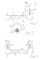
- Fig. 1 are a first end termination 1 and a second end termination 2 indicated schematically, between which a cryostat 3 is arranged. End terminations 1 and 2 and cryostat 3 are known per se. Their detailed structure is therefore not discussed here.
- An end termination 1 or 2 basically consists of a vacuum-insulated housing, in which all electrical components for connecting at least one electrical superconducting cable are included and which has a bushing for connecting further, to be operated at normal temperature electrical cable.
- a cryostat 3 basically consists of at least one metallic tube that is thermally insulated. Such a cryostat 3 can accordingly Fig. 2 Also, two spaced apart concentrically arranged metallic tubes 4 and 5, between which a vacuum insulation 6 is attached.
- cryostat 3 At least one electric superconducting cable SK is arranged, whose structure is also known in principle. It is therefore not discussed here.
- the cryostat 3 also encloses a free space FR through which liquid nitrogen is passed as coolant for the superconducting cable SK during operation of the system.
- the plant also includes a vacuum-insulated tank 7, which contains liquid nitrogen.
- the tank 7 is connected via a thermally insulated pipe 8, in which a pump 9 is connected to the first end termination 1.
- An optional second tank 10 is shown in dashed lines. It can then be connected to the first end closure 1 when in the first tank 7 is no longer contained sufficient liquid nitrogen.
- the tank 7 - possibly also the tank 10 - is connected via a thermally insulated pipe 11 to the second end termination 2.
- a pressure regulating valve 12 can be installed in the pipeline 11 prior to entry into the tank 7 (or 10).
- the tank 7 can then be refilled. In this sense, can be switched back and forth between the tanks 7 and 10 for an always sufficient supply of liquid nitrogen plant.
- the nitrogen heated at the end of the transfer section when the second end termination 2 is reached is returned to the tank 7 via the pipeline 11.
- the nitrogen can then evaporate in the tank 2.
- the cold gas generated during evaporation can be advantageous be used for additional cooling of the system components, for example, for cooling the end terminations.
- the gaseous phase of the nitrogen, which has been heated to almost ambient temperature, can be discharged to the environment.
- the method according to the invention can also be used with advantage if, in a DC transmission according to Fig. 3 two cryostats 13 and 14 are laid between the two end terminations 1 and 2, each of which contains a superconducting cable for the separate guidance of the two polarities.
- a further vacuum-insulated tank 15 can be arranged in the region of the second end termination, which contains liquid nitrogen.
- the nitrogen is optionally supplied to the second end termination 2 via a thermally insulated conduit 16 in which a pump 17 is connected.
- the method for cooling this system is advantageously carried out, for example, so that liquid nitrogen is fed to the first end termination 1 and pumped through the cryostat 13 to the second end termination 2. There, the heated nitrogen can be passed through a thermally insulated pipe 18 into the tank 15, with the above-described additional cooling effect of the cold gas.
- liquid nitrogen is fed from the tank 15 to the second end termination 2 and pumped through the cryostat 14 to the first end termination 1.
- the heated nitrogen can be passed from there via a thermally insulated pipe 19 into the tank 7.
- predetermined pressure levels in the system can be installed before the respective tank inlet in the returning pipe in this embodiment with two tanks 7 and 15, a pressure control valve.
Landscapes
- Engineering & Computer Science (AREA)
- Chemical & Material Sciences (AREA)
- Combustion & Propulsion (AREA)
- Physics & Mathematics (AREA)
- Mechanical Engineering (AREA)
- Thermal Sciences (AREA)
- General Engineering & Computer Science (AREA)
- Containers, Films, And Cooling For Superconductive Devices (AREA)
- Superconductors And Manufacturing Methods Therefor (AREA)
Abstract
Description
- Die Erfindung bezieht sich auf ein Verfahren zum Kühlen einer Anlage für supraleitfähige Kabel, welche zwei thermisch isolierte Endenabschlüsse und mindestens einen zwischen denselben angeordneten thermisch isolierten, rohrförmigen Kryostat aufweist, in dem mindestens ein supraleitfähiges Kabel angeordnet ist, mit welchem in einem Kühlmittelvorrat vorhandener, flüssiger Stickstoff mittels einer Pumpe durch einen ersten Endenabschluß und den Kryostat zu einem zweiten Endenabschluß gepumpt wird (
EP 2 328 156 Al ). - Supraleitfähige Kabel haben in heutiger Technik elektrische Leiter aus einem Verbundstoff, welcher keramisches Material enthält, das bei ausreichend tiefen Temperaturen in den supraleitfähigen Zustand übergeht. Der elektrische Gleichstromwiderstand eines entsprechend aufgebauten Leiters ist bei ausreichender Kühlung Null, solange eine bestimmte Stromstärke nicht überschritten wird. Geeignete keramische Materialien sind beispielsweise BSCCO (Wismut-Strontium-Kalzium-Kupfer-Oxid) als Material der 1. Generation oder ReBCO (Rareearth-Barium-Kupfer-Oxid), insbesondere YBCO (Yttrium-Barium-Kuofer-Oxid), als Materialien der 2. Generation. Derartige supraleitfähige Leiter werden in bekannter Technik mit flüssigem Stickstoff gekühlt, der dafür eine Betriebstemperatur von üblicherweise weniger als 77 K hat.
- Zum Kühlen des Stickstoffs auf die angegebene Temperatur werden bei bekannten Verfahren Kühlaggregate eingesetzt, an welche Pumpen angeschlossen sind, mittels derer der flüssige Stickstoff mit ausreichendem Druck in einen Endenabschluß und durch den Kryostat zum anderen, zweiten Endenabschluß gepumpt wird. Ein solches Verfahren ist beispielsweise in der eingangs erwähnten
EP 2 328 156 A1 beschrieben. Der Stickstoff kann vom zweiten Endenabschluß zur erneuten Kühlung auf Betriebstemperatur durch ein geeignetes Rohr zum jeweiligen Kühlaggregat zurückgeführt werden. Der Aufwand ist insgesamt hoch und die bekannten Kühlaggregate weisen Verschleißteile auf, die gegebenenfalls ausgetauscht werden müssen. Ein solches Kühlaggregat muß daher ständig gewartet werden. - Der Erfindung liegt die Aufgabe zugrunde, das eingangs geschilderte Verfahren zu vereinfachen.
- Diese Aufgabe wird gemäß der Erfindung dadurch gelöst,
- daß für den Kühlmittelvorrat mindestens ein vakuumisolierter Tank eingesetzt wird, in dem sich der auf Betriebstemperatur befindliche Stickstoff befindet und aus dem das Kühlmittel herausgepumpt wird, und
- daß zur Bereitstellung einer zum Betrieb der Anlage erforderlichen Menge an flüssigem Stickstoff der in dem Tank enthaltene Vorrat an flüssigem Stickstoff bei laufendem Betrieb ergänzt oder auf einen anderen, flüssigen Stickstoff enthaltenden Tank auf umgeschaltet wird.
- Dieses Verfahren arbeitet nahezu wartungsfrei, da Verschleißteile zur Kühlung des Stickstoffs nicht vorhanden sind. Ein mit flüssigem Stickstoff gefüllter Tank wird dem Anlagenbetreiber vom Erzeuger des Stickstoffs gegen Entgeld zur Verfügung gestellt. Der Stickstoff kann in bevorzugter Ausführungsform in zeitlichen Abständen bei laufendem Betrieb nachgefüllt werden. Es ist aber auch möglich, einen zweiten Tank einzusetzen, auf den die Versorgung der Anlage ohne Unterbrechung des Betriebs gegebenenfalls umgeschaltet wird.
- Der Stickstoff, der sich mit zunehmender Entfernung von der Einspeisestelle der Anlage nach und nach erwärmt, wird mit Vorteil in den Tank zurückgeführt, in welchem er verdampfen kann. Das beim Verdampfen erzeugte Kaltgas kann dann vorteilhaft zum zusätzlichen Kühlen der Anlagenkomponenten ausgenutzt werden, beispielsweise zum Kühlen der Endenabschlüsse.
- Wenn beispielsweise bei Gleichstrombetrieb der Anlage zwei Kryostate zwischen den beiden Endenabschlüssen angeordnet werden, von denen jeder ein supraleitfähiges Kabel enthält, dann kann auch an den zweiten Endenabschluß ein Tank mit flüssigem Stickstoff angeschlossen werden.
- Das Verfahren nach der Erfindung wird anhand der Zeichnungen in Ausführungsbeispielen erläutert.
- Es zeigen:
-
Fig. 1 in schematischer Darstellung eine Anlage mit mindestens einem supraleitfähigen Kabel. -
Fig. 2 einen Schnitt durchFig. 1 längs der Linie II - II in vergrößerter Darstellung. -
Fig. 3 eine gegenüberFig. 1 ergänzte Ausführungsform der Anlage. - In
Fig. 1 sind ein erster Endenabschluß 1 und ein zweiter Endenabschluß 2 schematisch angedeutet, zwischen denen ein Kryostat 3 angeordnet ist. Endenabschlüsse 1 und 2 sowie Kryostat 3 sind an sich bekannt. Auf ihren genaueren Aufbau wird daher hier nicht eingegangen. - Ein Endenabschluß 1 bzw. 2 besteht grundsätzlich aus einem vakuumisolierten Gehäuse, in dem alle elektrischen Bauteile zum Anschließen mindestens eines elektrischen supraleitfähigen Kabels enthalten sind und das eine Durchführung zum Anschluß weiterführender, bei Normaltemperatur zu betreibender elektrischer Kabel aufweist. Ein Kryostat 3 besteht grundsätzlich aus mindestens einem metallischen Rohr, das thermisch isoliert ist. Ein solcher Kryostat 3 kann entsprechend
Fig. 2 auch zwei mit Abstand konzentrisch zueinander angeordnete metallische Rohre 4 und 5 aufweisen, zwischen denen eine Vakuumisolierung 6 angebracht ist. - In dem Kryostat 3 ist mindestens ein elektrisches supraleitfähiges Kabel SK angeordnet, dessen Aufbau ebenfalls grundsätzlich bekannt ist. Es wird daher hier nicht auf denselben eingegangen. Der Kryostat 3 umschließt außerdem einen Freiraum FR, durch welchen beim Betrieb der Anlage flüssiger Stickstoff als Kühlmittel für das supraleitfähige Kabel SK geleitet wird.
- Zur Anlage gehört auch ein vakuumisolierter Tank 7, der flüssigen Stickstoff enthält. Der Tank 7 ist über eine thermisch isolierte Rohrleitung 8, in welcher eine Pumpe 9 angeschlossen ist, mit dem ersten Endenabschluß 1 verbunden. Ein gegebenenfalls vorhandener zweiter Tank 10 ist gestrichelt eingezeichnet. Er kann dann mit dem ersten Endenabschluß 1 verbunden werden, wenn in dem ersten Tank 7 nicht mehr genügend flüssiger Stickstoff enthalten ist. Der Tank 7 - gegebenenfalls auch der Tank 10 - ist über eine thermisch isolierte Rohrleitung 11 mit dem zweiten Endenabschluß 2 verbunden. Zur Aufrechterhaltung eines vorgebbaren Druckniveaus in der Anlage kann vor dem Einlauf in den Tank 7 (oder 10) ein Druckregelventil 12 in die Rohrleitung 11 eingebaut werden.
- Das Verfahren nach der Erfindung wird beispielsweise wie folgt durchgeführt:
- Nach Durchschaltung aller elektrischen Übertragungswege wird - vor tatsächlichem Einschalten der elektrischen Spannung - mittels der Pumpe 9 flüssiger Stickstoff in den ersten Endenabschluß 1 geleitet und mit ausreichendem Druck durch den Endenabschluß 1 und den Kryostat 3 zum zweiten Endenabschluß 2 gepumpt.
- Sobald das supraleitfähige Kabel SK ausreichend abgekühlt ist, kann dasselbe an eine elektrische Spannungsquelle angeschlossen werden. Die Kühlung des Kabels SK wird durch ständige Zufuhr von flüssigem Stickstoff aus dem Tank 7 aufrechterhalten.
- Der Vorrat an flüssigem Stickstoff wird mit Vorteil im Tank 7 bei laufendem Betrieb dauernd ergänzt, um ein für einen sicheren Betrieb der Anlage ausreichendes Niveau aufrechtzuerhalten.
- Gegebenenfalls kann zur Versorgung mit flüssigem Stickstoff auch auf den Tank 10 umgeschaltet werden. Der Tank 7 kann dann wieder aufgefüllt werden. In diesem Sinne kann für eine stets ausreichende Versorgung der Anlage mit flüssigem Stickstoff zwischen den Tanks 7 und 10 hin- und hergeschaltet werden.
- In einer bevorzugten Ausführungsform des Verfahrens wird der am Ende der Übertragungsstrecke beim Erreichen des zweiten Endenabschlusses 2 erwärmte Stickstoff über die Rohrleitung 11 in den Tank 7 zurückgeführt. Der Stickstoff kann dann im Tank 2 verdampfen. Das beim Verdampfen erzeugte Kaltgas kann vorteilhaft
zum zusätzlichen Kühlen der Anlagenkomponenten ausgenutzt werden, beispielsweise zum Kühlen der Endenabschlüsse. Die nahezu auf Umgebungstemperatur aufgewärmte gasförmige Phase des Stickstoffs kann an die Umgebung abgeführt werden. - Das Verfahren nach der Erfindung kann auch dann mit Vorteil verwendet werden, wenn bei einer Gleichstromübertragung gemäß
Fig. 3 zwei Kryostate 13 und 14 zwischen den beiden Endenabschlüssen 1 und 2 verlegt sind, von denen jeder zur getrennten Führung der beiden Polaritäten ein supraleitfähiges Kabel enthält. Bei einer solchen Anlage kann im Bereich des zweiten Endenabschlusses ein weiterer vakuumisolierter Tank 15 angeordnet werden, der flüssigen Stickstoff enthält. Der Stickstoff wird dem zweiten Endenabschluß 2 gegebenenfalls über eine thermisch isolierte Rohrleitung 16 zugeführt, in welcher eine Pumpe 17 angeschlossen ist. - Das Verfahren zur Kühlung dieser Anlage wird beispielsweise mit Vorteil so durchgeführt, daß flüssiger Stickstoff dem ersten Endenabschluß 1 zugeführt und durch den Kryostat 13 zum zweiten Endenabschluß 2 gepumpt wird. Dort kann der erwärmte Stickstoff über eine thermisch isolierte Rohrleitung 18 in den Tank 15 geführt werden, mit dem weiter oben geschilderten zusätzlichen Kühleffekt des Kaltgases.
- Gleichzeitig wird aus dem Tank 15 flüssiger Stickstoff dem zweiten Endenabschluß 2 zugeführt und durch den Kryostat 14 zum ersten Endenabschluß 1 gepumpt. Der erwärmte Stickstoff kann von dort aus über eine thermisch isolierte Rohrleitung 19 in den Tank 7 geführt werden.
- Zur Aufrechterhaltung eines bestimmten, vorgegebenen Druckniveaus in der Anlage kann auch bei dieser Ausführungsform mit zwei Tanks 7 und 15 ein Druckregelventil vor dem jeweiligen Tankeinlauf in die rückführende Rohrleitung eingebaut werden.
Claims (4)
- Verfahren zum Kühlen einer Anlage für supraleitfähige Kabel, welche zwei thermisch isolierte Endenabschlüsse und mindestens einen zwischen denselben angeordneten thermisch isolierten, rohrförmigen Kryostat aufweist, in dem mindestens ein supraleitfähiges Kabel angeordnet ist, mit welchem in einem Kühlmittelvorrat vorhandener, flüssiger Stickstoff mittels einer Pumpe durch einen ersten Endenabschluß und den Kryostat zu einem zweiten Endenabschluß gepumpt wird, dadurch gekennzeichnet,- daß für den Kühlmittelvorrat mindestens ein vakuumisolierter Tank (7) eingesetzt wird, in dem sich der auf Betriebstemperatur befindliche Stickstoff befindet und aus dem der Stickstoff herausgepumpt wird, und- daß zur Bereitstellung einer zum Betrieb der Anlage erforderlichen Menge an flüssigem Stickstoff der in dem Tank (7) enthaltene Vorrat an flüssigem Stickstoff bei laufendem Betrieb ergänzt oder auf einen anderen, flüssigen Stickstoff enthaltenden Tank (10) umgeschaltet wird.
- Verfahren nach Anspruch 1, dadurch gekennzeichnet,- daß der Stickstoff vom zweiten Endenabschluß (2) aus über eine thermisch isolierte Rohrleitung (11) in den Tank (7) zurückgeführt wird und- daß das dadurch durch Verdampfen erzeugte Kaltgas zum zusätzlichen Kühlen der Anlage verwendet wird.
- Verfahren nach Anspruch 2, dadurch gekennzeichnet, daß in die Rohrleitung (11) ein Druckregelventil (12) eingebaut wird.
- Verfahren nach Anspruch 1, dadurch gekennzeichnet,- daß zwischen den beiden Endenabschlüssen (1,2) zwei Kryostate (13,14) angeordnet werden, von denen jeder mindestens ein supraleitfähiges Kabel enthält,- daß bei jedem der beiden Endenabschlüsse (1,2) ein jeweils mit demselben verbundener, vakuumisolierter Tank (7,15) angeordnet wird und- daß der flüssige Stickstoff von dem einen Tank (7) aus durch einen der Kryostate (13) und von dem anderen Tank (15) aus durch den anderen Kryostat (14) gepumpt wird.
Priority Applications (3)
| Application Number | Priority Date | Filing Date | Title |
|---|---|---|---|
| EP11306694.8A EP2608223B1 (de) | 2011-12-19 | 2011-12-19 | Verfahren zum Kühlen einer Anlage für supraleitfähige Kabel |
| US13/693,172 US10151521B2 (en) | 2011-12-19 | 2012-12-04 | Method for cooling a plant for superconductive cables |
| CN201210548114.0A CN103165246B (zh) | 2011-12-19 | 2012-12-17 | 冷却用于超导电缆的设备的方法 |
Applications Claiming Priority (1)
| Application Number | Priority Date | Filing Date | Title |
|---|---|---|---|
| EP11306694.8A EP2608223B1 (de) | 2011-12-19 | 2011-12-19 | Verfahren zum Kühlen einer Anlage für supraleitfähige Kabel |
Publications (2)
| Publication Number | Publication Date |
|---|---|
| EP2608223A1 true EP2608223A1 (de) | 2013-06-26 |
| EP2608223B1 EP2608223B1 (de) | 2014-04-23 |
Family
ID=45470405
Family Applications (1)
| Application Number | Title | Priority Date | Filing Date |
|---|---|---|---|
| EP11306694.8A Not-in-force EP2608223B1 (de) | 2011-12-19 | 2011-12-19 | Verfahren zum Kühlen einer Anlage für supraleitfähige Kabel |
Country Status (3)
| Country | Link |
|---|---|
| US (1) | US10151521B2 (de) |
| EP (1) | EP2608223B1 (de) |
| CN (1) | CN103165246B (de) |
Cited By (2)
| Publication number | Priority date | Publication date | Assignee | Title |
|---|---|---|---|---|
| CN111578598A (zh) * | 2020-05-11 | 2020-08-25 | 嘉兴达宝文线缆有限公司 | 用于线缆加工的自适应冷却装置 |
| DE102020007043A1 (de) | 2020-11-18 | 2022-05-19 | Messer Se & Co. Kgaa | Vorrichtung zum Übertragen elektrischer Energie mit einem supraleitenden Stromträger |
Families Citing this family (14)
| Publication number | Priority date | Publication date | Assignee | Title |
|---|---|---|---|---|
| CN103500950B (zh) * | 2013-10-23 | 2015-12-30 | 国网浙江省电力公司嵊泗县供电公司 | 一种方形抽气式电缆冷却器 |
| CN103500951B (zh) * | 2013-10-23 | 2015-08-05 | 黄三甦 | 一种方形双向抽气式电缆冷却装置 |
| CN104713284A (zh) * | 2015-03-16 | 2015-06-17 | 芜湖凯博实业股份有限公司 | 一种电缆冷却系统及其控制方法 |
| CN105355319B (zh) * | 2015-12-03 | 2018-01-19 | 中国电力科学研究院 | 一种用于超导电缆的低温恒温器 |
| DE102018001040A1 (de) * | 2018-02-08 | 2019-08-08 | Messer Group Gmbh | Verfahren und Vorrichtung zum Kühlen eines supraleitenden Stromträgers |
| CN109323496A (zh) * | 2018-09-10 | 2019-02-12 | 成都深冷液化设备股份有限公司 | 以液氮或液空为冷源的充电电缆气体循环冷却方法 |
| CN110044499B (zh) * | 2019-04-15 | 2020-04-03 | 西南交通大学 | 一种配电网电缆终端异常温度检测降温装置及预警方法 |
| CN110853833B (zh) * | 2019-11-18 | 2021-02-12 | 中国科学院理化技术研究所 | 一种冷却超导电缆的装置 |
| EP3876371A1 (de) * | 2020-03-05 | 2021-09-08 | Nexans | Endverschluss für hochspannungskabel |
| CN112271027A (zh) * | 2020-10-14 | 2021-01-26 | 深圳供电局有限公司 | 一种用于超导电缆的单端顺流制冷系统 |
| CN112331409B (zh) * | 2020-10-14 | 2023-06-09 | 深圳供电局有限公司 | 一种用于超导电缆的双端逆流制冷系统 |
| WO2022108818A1 (en) | 2020-11-18 | 2022-05-27 | VEIR, Inc. | Suspended superconducting transmission lines |
| CA3198998A1 (en) | 2020-11-18 | 2022-05-27 | Stephen Paul Ashworth | Conductor systems for suspended or underground transmission lines |
| US11363741B2 (en) | 2020-11-18 | 2022-06-14 | VEIR, Inc. | Systems and methods for cooling of superconducting power transmission lines |
Citations (4)
| Publication number | Priority date | Publication date | Assignee | Title |
|---|---|---|---|---|
| US3882687A (en) * | 1973-01-25 | 1975-05-13 | Linde Ag | Method of and apparatus for the cooling of an object |
| US20070028636A1 (en) * | 2005-07-26 | 2007-02-08 | Royal John H | Cryogenic refrigeration system for superconducting devices |
| JP2010146867A (ja) * | 2008-12-19 | 2010-07-01 | Sharp Corp | 送電システム |
| EP2328156A1 (de) | 2009-11-26 | 2011-06-01 | Nexans | Verfahren zum Betrieb einer Anordnung mit mindestens einem supraleitfähigen Kabel |
Family Cites Families (9)
| Publication number | Priority date | Publication date | Assignee | Title |
|---|---|---|---|---|
| US3710584A (en) * | 1970-10-23 | 1973-01-16 | Cryogenic Eng Co | Low-loss closed-loop supply system for transferring liquified gas from a large container to a small container |
| CN2062806U (zh) * | 1989-02-23 | 1990-09-26 | 李循慎 | 液氮制(致)冷机 |
| US6354087B1 (en) * | 1998-05-22 | 2002-03-12 | Sumitomo Electric Industries, Ltd | Method and apparatus for cooling superconductor |
| US7201179B2 (en) * | 2003-09-23 | 2007-04-10 | Air Liquide Industrial U.S. Lp | Modular fluid supply system |
| US20050193743A1 (en) * | 2004-03-05 | 2005-09-08 | John Foss | High-pressure cryogenic gas for treatment processes |
| US7263845B2 (en) * | 2004-09-29 | 2007-09-04 | The Boc Group, Inc. | Backup cryogenic refrigeration system |
| US8511100B2 (en) * | 2005-06-30 | 2013-08-20 | General Electric Company | Cooling of superconducting devices by liquid storage and refrigeration unit |
| DK1821380T3 (da) * | 2006-02-16 | 2008-01-02 | Nexans | Fremgangsmåde til udlægning af et superlederkabel |
| IT1395266B1 (it) * | 2009-07-30 | 2012-09-05 | Deandrea | Modulo per la produzione di energia elettrica e centrale per la produzione di energia elettrica comprendente detto modulo. |
-
2011
- 2011-12-19 EP EP11306694.8A patent/EP2608223B1/de not_active Not-in-force
-
2012
- 2012-12-04 US US13/693,172 patent/US10151521B2/en not_active Expired - Fee Related
- 2012-12-17 CN CN201210548114.0A patent/CN103165246B/zh not_active Expired - Fee Related
Patent Citations (4)
| Publication number | Priority date | Publication date | Assignee | Title |
|---|---|---|---|---|
| US3882687A (en) * | 1973-01-25 | 1975-05-13 | Linde Ag | Method of and apparatus for the cooling of an object |
| US20070028636A1 (en) * | 2005-07-26 | 2007-02-08 | Royal John H | Cryogenic refrigeration system for superconducting devices |
| JP2010146867A (ja) * | 2008-12-19 | 2010-07-01 | Sharp Corp | 送電システム |
| EP2328156A1 (de) | 2009-11-26 | 2011-06-01 | Nexans | Verfahren zum Betrieb einer Anordnung mit mindestens einem supraleitfähigen Kabel |
Cited By (3)
| Publication number | Priority date | Publication date | Assignee | Title |
|---|---|---|---|---|
| CN111578598A (zh) * | 2020-05-11 | 2020-08-25 | 嘉兴达宝文线缆有限公司 | 用于线缆加工的自适应冷却装置 |
| DE102020007043A1 (de) | 2020-11-18 | 2022-05-19 | Messer Se & Co. Kgaa | Vorrichtung zum Übertragen elektrischer Energie mit einem supraleitenden Stromträger |
| WO2022106131A1 (de) | 2020-11-18 | 2022-05-27 | Messer Group Gmbh | Vorrichtung zum übertragen elektrischer energie mit einem supraleitenden stromträger |
Also Published As
| Publication number | Publication date |
|---|---|
| EP2608223B1 (de) | 2014-04-23 |
| US20140150471A1 (en) | 2014-06-05 |
| US10151521B2 (en) | 2018-12-11 |
| CN103165246A (zh) | 2013-06-19 |
| CN103165246B (zh) | 2016-12-28 |
Similar Documents
| Publication | Publication Date | Title |
|---|---|---|
| EP2608223B1 (de) | Verfahren zum Kühlen einer Anlage für supraleitfähige Kabel | |
| EP3017238B1 (de) | Vorrichtung zum kühlen eines verbrauchers mit einer unterkühlten flüssigkeit in einem kühlkreislauf | |
| DE3633313C2 (de) | ||
| EP2418747B1 (de) | Anordnung zum elektrisch leitenden Verbinden von zwei elektrischen Einheiten | |
| EP2698794B1 (de) | Anordnung mit mindestens einem supraleitfähigen Kabel | |
| EP1865516B1 (de) | System mit einem supraleitfähigen Kabel | |
| EP2685469B1 (de) | Anordnung mit mindestens einem supraleitfähigen Kabel | |
| EP2328156B1 (de) | Verfahren zum Betrieb einer Anordnung mit mindestens einem supraleitfähigen Kabel | |
| EP2770514B1 (de) | Verfahren zum Kühlen eines supraleitfähigen Kabels | |
| EP2383854A1 (de) | Anordnung mit einem supraleitfähigen Kabel | |
| DE102012016292B4 (de) | Verfahren und Vorrichtung zum Kühlen von Objekten | |
| EP2693584A1 (de) | Anordnung mit mindestens einem supraleitfähigen Kabel | |
| EP2690737B1 (de) | Anordnung mit drei supraleitfähigen Phasenleitern | |
| EP2426676A1 (de) | Anordnung mit mindestens einem supraleitfähigen Kabel | |
| WO2022106131A1 (de) | Vorrichtung zum übertragen elektrischer energie mit einem supraleitenden stromträger | |
| EP0082409B1 (de) | Thermisches Verfahren zum schnellen Überführen einer supraleitenden Wicklung vom supraleitenden in den normalleitenden Zustand und Vorrichtung zur Durchführung des Verfahrens | |
| EP2339593A1 (de) | Supraleitfähiges Kabelsystem | |
| EP3749903B1 (de) | Verfahren und vorrichtung zum kühlen eines supraleitenden stromträgers | |
| DE202019003381U1 (de) | Muffe für ein supraleitfähiges Kabel und supraleitfähiges Kabel mit Anschluss für eine Zwischenkühlung | |
| DE2114538A1 (de) | Verfahren zur Kühlung eines elektrischen Organes in einer durch Wärmeschilder thermisch isolierten Kammer | |
| EP2221833A1 (de) | Anordnung zur Stromversorgung von Verbrauchern elektrischen Stroms | |
| EP3376133B1 (de) | Verfahren und vorrichtung zum kühlen einer anordnung mit einer stromführung sowie system mit entsprechender vorrichtung | |
| EP2587492B1 (de) | Vorrichtung zum Kühlen mindestens eines supraleitfähigen Kabels | |
| EP2200048A1 (de) | Anordnung mit mindestens einem supraleitfähigen Kabel | |
| EP3503329B1 (de) | Verfahren zum kühlen eines supraleitfähigen kabelsystems |
Legal Events
| Date | Code | Title | Description |
|---|---|---|---|
| 17P | Request for examination filed |
Effective date: 20120529 |
|
| AK | Designated contracting states |
Kind code of ref document: A1 Designated state(s): AL AT BE BG CH CY CZ DE DK EE ES FI FR GB GR HR HU IE IS IT LI LT LU LV MC MK MT NL NO PL PT RO RS SE SI SK SM TR |
|
| AX | Request for extension of the european patent |
Extension state: BA ME |
|
| PUAI | Public reference made under article 153(3) epc to a published international application that has entered the european phase |
Free format text: ORIGINAL CODE: 0009012 |
|
| GRAP | Despatch of communication of intention to grant a patent |
Free format text: ORIGINAL CODE: EPIDOSNIGR1 |
|
| RIC1 | Information provided on ipc code assigned before grant |
Ipc: H01B 12/16 20060101AFI20131024BHEP Ipc: F25D 3/10 20060101ALN20131024BHEP |
|
| INTG | Intention to grant announced |
Effective date: 20131119 |
|
| GRAS | Grant fee paid |
Free format text: ORIGINAL CODE: EPIDOSNIGR3 |
|
| GRAA | (expected) grant |
Free format text: ORIGINAL CODE: 0009210 |
|
| AK | Designated contracting states |
Kind code of ref document: B1 Designated state(s): AL AT BE BG CH CY CZ DE DK EE ES FI FR GB GR HR HU IE IS IT LI LT LU LV MC MK MT NL NO PL PT RO RS SE SI SK SM TR |
|
| REG | Reference to a national code |
Ref country code: GB Ref legal event code: FG4D Free format text: NOT ENGLISH |
|
| REG | Reference to a national code |
Ref country code: CH Ref legal event code: EP |
|
| REG | Reference to a national code |
Ref country code: AT Ref legal event code: REF Ref document number: 664251 Country of ref document: AT Kind code of ref document: T Effective date: 20140515 |
|
| REG | Reference to a national code |
Ref country code: IE Ref legal event code: FG4D Free format text: LANGUAGE OF EP DOCUMENT: GERMAN |
|
| REG | Reference to a national code |
Ref country code: DE Ref legal event code: R096 Ref document number: 502011002812 Country of ref document: DE Effective date: 20140528 |
|
| REG | Reference to a national code |
Ref country code: NL Ref legal event code: T3 |
|
| REG | Reference to a national code |
Ref country code: LT Ref legal event code: MG4D |
|
| PG25 | Lapsed in a contracting state [announced via postgrant information from national office to epo] |
Ref country code: NO Free format text: LAPSE BECAUSE OF FAILURE TO SUBMIT A TRANSLATION OF THE DESCRIPTION OR TO PAY THE FEE WITHIN THE PRESCRIBED TIME-LIMIT Effective date: 20140723 Ref country code: CY Free format text: LAPSE BECAUSE OF FAILURE TO SUBMIT A TRANSLATION OF THE DESCRIPTION OR TO PAY THE FEE WITHIN THE PRESCRIBED TIME-LIMIT Effective date: 20140423 Ref country code: FI Free format text: LAPSE BECAUSE OF FAILURE TO SUBMIT A TRANSLATION OF THE DESCRIPTION OR TO PAY THE FEE WITHIN THE PRESCRIBED TIME-LIMIT Effective date: 20140423 Ref country code: GR Free format text: LAPSE BECAUSE OF FAILURE TO SUBMIT A TRANSLATION OF THE DESCRIPTION OR TO PAY THE FEE WITHIN THE PRESCRIBED TIME-LIMIT Effective date: 20140724 Ref country code: IS Free format text: LAPSE BECAUSE OF FAILURE TO SUBMIT A TRANSLATION OF THE DESCRIPTION OR TO PAY THE FEE WITHIN THE PRESCRIBED TIME-LIMIT Effective date: 20140823 Ref country code: LT Free format text: LAPSE BECAUSE OF FAILURE TO SUBMIT A TRANSLATION OF THE DESCRIPTION OR TO PAY THE FEE WITHIN THE PRESCRIBED TIME-LIMIT Effective date: 20140423 Ref country code: BG Free format text: LAPSE BECAUSE OF FAILURE TO SUBMIT A TRANSLATION OF THE DESCRIPTION OR TO PAY THE FEE WITHIN THE PRESCRIBED TIME-LIMIT Effective date: 20140723 |
|
| PG25 | Lapsed in a contracting state [announced via postgrant information from national office to epo] |
Ref country code: ES Free format text: LAPSE BECAUSE OF FAILURE TO SUBMIT A TRANSLATION OF THE DESCRIPTION OR TO PAY THE FEE WITHIN THE PRESCRIBED TIME-LIMIT Effective date: 20140423 Ref country code: HR Free format text: LAPSE BECAUSE OF FAILURE TO SUBMIT A TRANSLATION OF THE DESCRIPTION OR TO PAY THE FEE WITHIN THE PRESCRIBED TIME-LIMIT Effective date: 20140423 Ref country code: RS Free format text: LAPSE BECAUSE OF FAILURE TO SUBMIT A TRANSLATION OF THE DESCRIPTION OR TO PAY THE FEE WITHIN THE PRESCRIBED TIME-LIMIT Effective date: 20140423 Ref country code: SE Free format text: LAPSE BECAUSE OF FAILURE TO SUBMIT A TRANSLATION OF THE DESCRIPTION OR TO PAY THE FEE WITHIN THE PRESCRIBED TIME-LIMIT Effective date: 20140423 Ref country code: PL Free format text: LAPSE BECAUSE OF FAILURE TO SUBMIT A TRANSLATION OF THE DESCRIPTION OR TO PAY THE FEE WITHIN THE PRESCRIBED TIME-LIMIT Effective date: 20140423 Ref country code: LV Free format text: LAPSE BECAUSE OF FAILURE TO SUBMIT A TRANSLATION OF THE DESCRIPTION OR TO PAY THE FEE WITHIN THE PRESCRIBED TIME-LIMIT Effective date: 20140423 |
|
| PG25 | Lapsed in a contracting state [announced via postgrant information from national office to epo] |
Ref country code: PT Free format text: LAPSE BECAUSE OF FAILURE TO SUBMIT A TRANSLATION OF THE DESCRIPTION OR TO PAY THE FEE WITHIN THE PRESCRIBED TIME-LIMIT Effective date: 20140825 |
|
| REG | Reference to a national code |
Ref country code: DE Ref legal event code: R097 Ref document number: 502011002812 Country of ref document: DE |
|
| PG25 | Lapsed in a contracting state [announced via postgrant information from national office to epo] |
Ref country code: CZ Free format text: LAPSE BECAUSE OF FAILURE TO SUBMIT A TRANSLATION OF THE DESCRIPTION OR TO PAY THE FEE WITHIN THE PRESCRIBED TIME-LIMIT Effective date: 20140423 Ref country code: RO Free format text: LAPSE BECAUSE OF FAILURE TO SUBMIT A TRANSLATION OF THE DESCRIPTION OR TO PAY THE FEE WITHIN THE PRESCRIBED TIME-LIMIT Effective date: 20140423 Ref country code: DK Free format text: LAPSE BECAUSE OF FAILURE TO SUBMIT A TRANSLATION OF THE DESCRIPTION OR TO PAY THE FEE WITHIN THE PRESCRIBED TIME-LIMIT Effective date: 20140423 Ref country code: EE Free format text: LAPSE BECAUSE OF FAILURE TO SUBMIT A TRANSLATION OF THE DESCRIPTION OR TO PAY THE FEE WITHIN THE PRESCRIBED TIME-LIMIT Effective date: 20140423 Ref country code: SK Free format text: LAPSE BECAUSE OF FAILURE TO SUBMIT A TRANSLATION OF THE DESCRIPTION OR TO PAY THE FEE WITHIN THE PRESCRIBED TIME-LIMIT Effective date: 20140423 |
|
| PLBE | No opposition filed within time limit |
Free format text: ORIGINAL CODE: 0009261 |
|
| STAA | Information on the status of an ep patent application or granted ep patent |
Free format text: STATUS: NO OPPOSITION FILED WITHIN TIME LIMIT |
|
| PG25 | Lapsed in a contracting state [announced via postgrant information from national office to epo] |
Ref country code: IT Free format text: LAPSE BECAUSE OF FAILURE TO SUBMIT A TRANSLATION OF THE DESCRIPTION OR TO PAY THE FEE WITHIN THE PRESCRIBED TIME-LIMIT Effective date: 20140423 |
|
| 26N | No opposition filed |
Effective date: 20150126 |
|
| REG | Reference to a national code |
Ref country code: DE Ref legal event code: R097 Ref document number: 502011002812 Country of ref document: DE Effective date: 20150126 |
|
| PG25 | Lapsed in a contracting state [announced via postgrant information from national office to epo] |
Ref country code: BE Free format text: LAPSE BECAUSE OF NON-PAYMENT OF DUE FEES Effective date: 20141231 |
|
| PG25 | Lapsed in a contracting state [announced via postgrant information from national office to epo] |
Ref country code: SI Free format text: LAPSE BECAUSE OF FAILURE TO SUBMIT A TRANSLATION OF THE DESCRIPTION OR TO PAY THE FEE WITHIN THE PRESCRIBED TIME-LIMIT Effective date: 20140423 Ref country code: LU Free format text: LAPSE BECAUSE OF FAILURE TO SUBMIT A TRANSLATION OF THE DESCRIPTION OR TO PAY THE FEE WITHIN THE PRESCRIBED TIME-LIMIT Effective date: 20141219 |
|
| REG | Reference to a national code |
Ref country code: CH Ref legal event code: PL |
|
| REG | Reference to a national code |
Ref country code: IE Ref legal event code: MM4A |
|
| PG25 | Lapsed in a contracting state [announced via postgrant information from national office to epo] |
Ref country code: IE Free format text: LAPSE BECAUSE OF NON-PAYMENT OF DUE FEES Effective date: 20141219 Ref country code: CH Free format text: LAPSE BECAUSE OF NON-PAYMENT OF DUE FEES Effective date: 20141231 Ref country code: LI Free format text: LAPSE BECAUSE OF NON-PAYMENT OF DUE FEES Effective date: 20141231 |
|
| REG | Reference to a national code |
Ref country code: FR Ref legal event code: PLFP Year of fee payment: 5 |
|
| PG25 | Lapsed in a contracting state [announced via postgrant information from national office to epo] |
Ref country code: SM Free format text: LAPSE BECAUSE OF FAILURE TO SUBMIT A TRANSLATION OF THE DESCRIPTION OR TO PAY THE FEE WITHIN THE PRESCRIBED TIME-LIMIT Effective date: 20140423 |
|
| PG25 | Lapsed in a contracting state [announced via postgrant information from national office to epo] |
Ref country code: MC Free format text: LAPSE BECAUSE OF FAILURE TO SUBMIT A TRANSLATION OF THE DESCRIPTION OR TO PAY THE FEE WITHIN THE PRESCRIBED TIME-LIMIT Effective date: 20140423 |
|
| PG25 | Lapsed in a contracting state [announced via postgrant information from national office to epo] |
Ref country code: HU Free format text: LAPSE BECAUSE OF FAILURE TO SUBMIT A TRANSLATION OF THE DESCRIPTION OR TO PAY THE FEE WITHIN THE PRESCRIBED TIME-LIMIT; INVALID AB INITIO Effective date: 20111219 Ref country code: MT Free format text: LAPSE BECAUSE OF FAILURE TO SUBMIT A TRANSLATION OF THE DESCRIPTION OR TO PAY THE FEE WITHIN THE PRESCRIBED TIME-LIMIT Effective date: 20140423 Ref country code: TR Free format text: LAPSE BECAUSE OF FAILURE TO SUBMIT A TRANSLATION OF THE DESCRIPTION OR TO PAY THE FEE WITHIN THE PRESCRIBED TIME-LIMIT Effective date: 20140423 |
|
| REG | Reference to a national code |
Ref country code: FR Ref legal event code: PLFP Year of fee payment: 6 |
|
| REG | Reference to a national code |
Ref country code: FR Ref legal event code: PLFP Year of fee payment: 7 |
|
| REG | Reference to a national code |
Ref country code: AT Ref legal event code: MM01 Ref document number: 664251 Country of ref document: AT Kind code of ref document: T Effective date: 20161219 |
|
| PG25 | Lapsed in a contracting state [announced via postgrant information from national office to epo] |
Ref country code: AT Free format text: LAPSE BECAUSE OF NON-PAYMENT OF DUE FEES Effective date: 20161219 |
|
| PG25 | Lapsed in a contracting state [announced via postgrant information from national office to epo] |
Ref country code: MK Free format text: LAPSE BECAUSE OF FAILURE TO SUBMIT A TRANSLATION OF THE DESCRIPTION OR TO PAY THE FEE WITHIN THE PRESCRIBED TIME-LIMIT Effective date: 20140423 |
|
| PG25 | Lapsed in a contracting state [announced via postgrant information from national office to epo] |
Ref country code: AL Free format text: LAPSE BECAUSE OF FAILURE TO SUBMIT A TRANSLATION OF THE DESCRIPTION OR TO PAY THE FEE WITHIN THE PRESCRIBED TIME-LIMIT Effective date: 20140423 |
|
| PGFP | Annual fee paid to national office [announced via postgrant information from national office to epo] |
Ref country code: GB Payment date: 20211222 Year of fee payment: 11 Ref country code: FR Payment date: 20211224 Year of fee payment: 11 Ref country code: DE Payment date: 20211210 Year of fee payment: 11 |
|
| PGFP | Annual fee paid to national office [announced via postgrant information from national office to epo] |
Ref country code: NL Payment date: 20211221 Year of fee payment: 11 |
|
| REG | Reference to a national code |
Ref country code: DE Ref legal event code: R119 Ref document number: 502011002812 Country of ref document: DE |
|
| REG | Reference to a national code |
Ref country code: NL Ref legal event code: MM Effective date: 20230101 |
|
| GBPC | Gb: european patent ceased through non-payment of renewal fee |
Effective date: 20221219 |
|
| PG25 | Lapsed in a contracting state [announced via postgrant information from national office to epo] |
Ref country code: NL Free format text: LAPSE BECAUSE OF NON-PAYMENT OF DUE FEES Effective date: 20230101 |
|
| PG25 | Lapsed in a contracting state [announced via postgrant information from national office to epo] |
Ref country code: GB Free format text: LAPSE BECAUSE OF NON-PAYMENT OF DUE FEES Effective date: 20221219 Ref country code: DE Free format text: LAPSE BECAUSE OF NON-PAYMENT OF DUE FEES Effective date: 20230701 |
|
| PG25 | Lapsed in a contracting state [announced via postgrant information from national office to epo] |
Ref country code: FR Free format text: LAPSE BECAUSE OF NON-PAYMENT OF DUE FEES Effective date: 20221231 |