EP3708760B1 - Drainagesystem für horizontal verschiebbare türen und fenster - Google Patents
Drainagesystem für horizontal verschiebbare türen und fenster Download PDFInfo
- Publication number
- EP3708760B1 EP3708760B1 EP20161984.8A EP20161984A EP3708760B1 EP 3708760 B1 EP3708760 B1 EP 3708760B1 EP 20161984 A EP20161984 A EP 20161984A EP 3708760 B1 EP3708760 B1 EP 3708760B1
- Authority
- EP
- European Patent Office
- Prior art keywords
- tray
- drainage
- shaped body
- front wall
- door
- Prior art date
- Legal status (The legal status is an assumption and is not a legal conclusion. Google has not performed a legal analysis and makes no representation as to the accuracy of the status listed.)
- Active
Links
Images


Classifications
-
- E—FIXED CONSTRUCTIONS
- E06—DOORS, WINDOWS, SHUTTERS, OR ROLLER BLINDS IN GENERAL; LADDERS
- E06B—FIXED OR MOVABLE CLOSURES FOR OPENINGS IN BUILDINGS, VEHICLES, FENCES OR LIKE ENCLOSURES IN GENERAL, e.g. DOORS, WINDOWS, BLINDS, GATES
- E06B7/00—Special arrangements or measures in connection with doors or windows
- E06B7/14—Measures for draining-off condensed water or water leaking-in frame members for draining off condensation water, throats at the bottom of a sash
-
- E—FIXED CONSTRUCTIONS
- E05—LOCKS; KEYS; WINDOW OR DOOR FITTINGS; SAFES
- E05D—HINGES OR SUSPENSION DEVICES FOR DOORS, WINDOWS OR WINGS
- E05D15/00—Suspension arrangements for wings
- E05D15/06—Suspension arrangements for wings for wings sliding horizontally more or less in their own plane
- E05D15/0621—Details, e.g. suspension or supporting guides
- E05D15/066—Details, e.g. suspension or supporting guides for wings supported at the bottom
- E05D15/0686—Tracks
-
- E—FIXED CONSTRUCTIONS
- E06—DOORS, WINDOWS, SHUTTERS, OR ROLLER BLINDS IN GENERAL; LADDERS
- E06B—FIXED OR MOVABLE CLOSURES FOR OPENINGS IN BUILDINGS, VEHICLES, FENCES OR LIKE ENCLOSURES IN GENERAL, e.g. DOORS, WINDOWS, BLINDS, GATES
- E06B3/00—Window sashes, door leaves, or like elements for closing wall or like openings; Layout of fixed or moving closures, e.g. windows in wall or like openings; Features of rigidly-mounted outer frames relating to the mounting of wing frames
- E06B3/32—Arrangements of wings characterised by the manner of movement; Arrangements of movable wings in openings; Features of wings or frames relating solely to the manner of movement of the wing
- E06B3/34—Arrangements of wings characterised by the manner of movement; Arrangements of movable wings in openings; Features of wings or frames relating solely to the manner of movement of the wing with only one kind of movement
- E06B3/42—Sliding wings; Details of frames with respect to guiding
- E06B3/46—Horizontally-sliding wings
- E06B3/4609—Horizontally-sliding wings for windows
-
- E—FIXED CONSTRUCTIONS
- E06—DOORS, WINDOWS, SHUTTERS, OR ROLLER BLINDS IN GENERAL; LADDERS
- E06B—FIXED OR MOVABLE CLOSURES FOR OPENINGS IN BUILDINGS, VEHICLES, FENCES OR LIKE ENCLOSURES IN GENERAL, e.g. DOORS, WINDOWS, BLINDS, GATES
- E06B3/00—Window sashes, door leaves, or like elements for closing wall or like openings; Layout of fixed or moving closures, e.g. windows in wall or like openings; Features of rigidly-mounted outer frames relating to the mounting of wing frames
- E06B3/32—Arrangements of wings characterised by the manner of movement; Arrangements of movable wings in openings; Features of wings or frames relating solely to the manner of movement of the wing
- E06B3/34—Arrangements of wings characterised by the manner of movement; Arrangements of movable wings in openings; Features of wings or frames relating solely to the manner of movement of the wing with only one kind of movement
- E06B3/42—Sliding wings; Details of frames with respect to guiding
- E06B3/46—Horizontally-sliding wings
- E06B3/4636—Horizontally-sliding wings for doors
-
- E—FIXED CONSTRUCTIONS
- E06—DOORS, WINDOWS, SHUTTERS, OR ROLLER BLINDS IN GENERAL; LADDERS
- E06B—FIXED OR MOVABLE CLOSURES FOR OPENINGS IN BUILDINGS, VEHICLES, FENCES OR LIKE ENCLOSURES IN GENERAL, e.g. DOORS, WINDOWS, BLINDS, GATES
- E06B7/00—Special arrangements or measures in connection with doors or windows
- E06B7/26—Rain or draught deflectors, e.g. under sliding wings also protection against light for doors
-
- E—FIXED CONSTRUCTIONS
- E05—LOCKS; KEYS; WINDOW OR DOOR FITTINGS; SAFES
- E05Y—INDEXING SCHEME ASSOCIATED WITH SUBCLASSES E05D AND E05F, RELATING TO CONSTRUCTION ELEMENTS, ELECTRIC CONTROL, POWER SUPPLY, POWER SIGNAL OR TRANSMISSION, USER INTERFACES, MOUNTING OR COUPLING, DETAILS, ACCESSORIES, AUXILIARY OPERATIONS NOT OTHERWISE PROVIDED FOR, APPLICATION THEREOF
- E05Y2800/00—Details, accessories and auxiliary operations not otherwise provided for
- E05Y2800/40—Physical or chemical protection
- E05Y2800/428—Physical or chemical protection against water or ice
-
- E—FIXED CONSTRUCTIONS
- E05—LOCKS; KEYS; WINDOW OR DOOR FITTINGS; SAFES
- E05Y—INDEXING SCHEME ASSOCIATED WITH SUBCLASSES E05D AND E05F, RELATING TO CONSTRUCTION ELEMENTS, ELECTRIC CONTROL, POWER SUPPLY, POWER SIGNAL OR TRANSMISSION, USER INTERFACES, MOUNTING OR COUPLING, DETAILS, ACCESSORIES, AUXILIARY OPERATIONS NOT OTHERWISE PROVIDED FOR, APPLICATION THEREOF
- E05Y2900/00—Application of doors, windows, wings or fittings thereof
- E05Y2900/10—Application of doors, windows, wings or fittings thereof for buildings or parts thereof
- E05Y2900/13—Type of wing
- E05Y2900/132—Doors
-
- E—FIXED CONSTRUCTIONS
- E05—LOCKS; KEYS; WINDOW OR DOOR FITTINGS; SAFES
- E05Y—INDEXING SCHEME ASSOCIATED WITH SUBCLASSES E05D AND E05F, RELATING TO CONSTRUCTION ELEMENTS, ELECTRIC CONTROL, POWER SUPPLY, POWER SIGNAL OR TRANSMISSION, USER INTERFACES, MOUNTING OR COUPLING, DETAILS, ACCESSORIES, AUXILIARY OPERATIONS NOT OTHERWISE PROVIDED FOR, APPLICATION THEREOF
- E05Y2900/00—Application of doors, windows, wings or fittings thereof
- E05Y2900/10—Application of doors, windows, wings or fittings thereof for buildings or parts thereof
- E05Y2900/13—Type of wing
- E05Y2900/148—Windows
Definitions
- the present invention relates to a drainage system for horizontally sliding doors or windows, according to the preamble of claim 1 and to a drainage tray for such a drainage system, according to claim 20.
- the aim is to prevent water penetrating into the environment closed by the door or window and stagnating in the door or window itself, as well as limiting the inlet of air from the outside towards the inside of the environment closed by the door or window.
- the lower transverse element comprises one or more rails or guides for the support and sliding of respective door or window leaves.
- a longitudinal channel runs, which is open at the top.
- transverse element T provided with a pair of rails R between which a sealing dowel U is interposed, which separates the "outer side” which is turned towards the environment AE external to the compartment closed by the door or window, from the “inner side”, which is turned towards the environment AI internal to such compartment.
- Known drainage systems consist of the provision in the transverse element T of a plurality of openings that are in fluid communication with one another and that form a drainage path P that discharges into the external environment.
- the opening that opens directly into the external environment is generally covered with a cap C that is open at the bottom for discharging the drained water.
- the cap C is inserted with a snap fitting into the respective opening obtained in the transverse element and is generally provided with a movable doors adapted to prevent the entry of air from the outside to the inside.
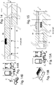
- Figures 12, 12A and 12B show an "outer side” drainage system and Figures 13, 13A and 13B show an “inner side” drainage system, such systems being able to be combined with one another.
- FIG. 15, 15A, 15B Another known drainage system
- Figures 15, 15A, 15B which entails the use of a drainage tray V which is inserted slidingly in relevant slots obtained in the transverse element T and into which at least one drainage opening opens, which drainage opening is obtained on the bottom of the channel that runs parallel to the rails and into which an outflow bushing B is inserted.
- the drainage tray V is provided with a front wall crossed by at least one discharge opening protected by a covering cap.
- Such a known drainage system is generally used for "outer side" drainage and, with respect to the known drainage systems as described above, it has greater drainage capacity and allows stagnation in the tubular ducts internal to the transverse element to be prevented.
- the aim of the present invention is that of providing a drainage system for horizontally sliding doors or windows that has a high drainage capacity and prevents the diffusion of the drained water into the tubular duct internal to the transverse element and consequent stagnation thereof.
- Another aim of the present invention is that of providing a drainage system for horizontally sliding doors or windows that can be easily adopted on transverse elements with a different configuration and dimensions for draining both of the "inner side” and of the "outer side", eliminating infiltrations of air into the environment closed by the door or window.
- Still another aim of the present invention is that of providing a drainage system for horizontally sliding doors or windows that can be easily mounted and dismounted with a limited number of operations.
- a drainage system 10 for horizontally sliding doors or windows according to the present invention is shown.
- Such doors or windows comprise a fixed frame on which one or more leaves of a window or a door are mounted, at least one of which is supported in a horizontally sliding way.
- the fixed frame comprises a lower transverse element 100 which is generally constituted by one or more extruded profiles coupled to one another and/or provided with sealing and/or thermally insulating gaskets and that are not described in detail being they known to a person skilled in the art.
- the transverse element 100 comprises at least one rail 101 or guide adapted to support at least one leaf 200 of a door or window.
- the transverse element 100 comprises at least two rails 101 or guides parallel to one another, on each of which a respective leaf 200 is mounted, wherein one of the two leaves 200 is mounted slidably onto the respective rail 101 or guide.
- the transverse element 100 can also be provided with more rails or guides each supporting a respective fixed or sliding leaf according to configurations known to a person skilled in the art.
- At least one channel 102 runs parallel to the rails 101.
- the channel 102 is generally open at the top and is delimited along at least one side by a rail 101.
- the transverse element 100 then comprises at least one tubular duct 103 that extends along the longitudinal extension of the transverse element itself and internally thereto.
- the tubular duct 103 has an outer lateral wall 104 and an upper wall 105 that defines the bottom of the channel 102.
- Outer lateral wall 104 means the wall that longitudinally delimits the tubular duct 103 and which, in the mounting configuration of the door or window, faces the environment external to the compartment closed by the door or window itself.
- AE schematically indicates the external environment and AI the internal environment to the compartment closed by the door or window.
- tubular duct 103 may be of the type with one or more internal chambers separated from one another by intermediate walls 130 according to the configuration of the transverse element 100.
- the upper wall 105 is crossed by at least one drainage opening 106 and the outer lateral wall 104 is crossed by at least one slot 107.
- the drainage opening 106 and the slot 107 are obtained at the same longitudinal portion of the transverse element 100.
- each intermediate wall 130 interposed between the outer lateral wall 104 and the drainage opening 106 is crossed by at least one respective slot that matches and is aligned with the slot 107.
- the drainage system 10 comprises at least one drainage tray 11 (indicated for simplicity purposes below as tray 11) which can be inserted transversally into the tubular duct 103 through the slot 107 and that is adapted to extend below the drainage opening 106.
- the tray 11 has a front wall 12 and a rear wall 13 opposite one another along the longitudinal extension of the tray 11.
- the front wall 12 is adapted to cover the slot 107 and is provided with at least one discharge opening 14 that leads into the external environment AE for discharging the drained water therein.
- the rear wall 13 is adapted to be housed in the tubular duct 103, generally beyond the edge of the drainage opening 106 further from the outer lateral wall 104.
- the tray 11 comprises:
- the first tray-shaped body 15 and the second tray-shaped body 16 can be coupled to one another in one of a plurality of different relative positions along a direction D perpendicular to the front wall 12 and to the rear wall 13 for regulating the length of the tray 11 as a function of the distance H between the slot 107 and the drainage opening 106, a distance that is measured on a plane perpendicular to the longitudinal extension of the tubular duct 103.
- the distance H is defined between the outer lateral wall 104 and the edge of the drainage opening 106 which, on a plane transverse to the longitudinal extension of the tubular duct 103, is more distant therefrom.
- the length of the tray 11 is thus regulated as a function of the maximum distance between the slot 107 and the drainage opening 106, so that the first is greater than or equal to the second one so that the tray 11 extends in length below the entire drainage opening 106 to collect the water that flows out therefrom.
- the useful width of the tray 11 - and, therefore, of the first tray-shaped body 15 and of the second tray-shaped body 16 that constitute it - is greater than or equal to the maximum size that the drainage opening 106 has parallel to the longitudinal extension of the tubular duct 103, so that the tray 11 extends, not only in length, but also in width below the entire drainage opening 106.
- the drainage opening 16 is contained in the useful dimensions of the tray 11.
- the first tray-shaped body 15 comprises a bottom 15a connected with the front wall 12 extending along a plane substantially perpendicular to the same and a pair of lateral sides boards 15b joining the bottom 15a with the front wall 12.
- the bottom 15a and the lateral sides boards 15b extend from the face of the front wall 12 which, in the mounting configuration, faces the rear wall 13.
- the second tray-shaped body 16 comprises a bottom 16a connected with the rear wall 13 extending on a plane substantially perpendicular thereto and a pair of lateral sides boards 16b that join the bottom 16a to the rear wall 13.
- the bottom 16a and the lateral sides boards 16b extend from the face of the rear wall 13 which, in the mounting configuration, faces the front wall 12.
- the volume delimited by the first tray-shaped body 15 is adapted to contain at least one portion of the second tray-shaped body 16, advantageously the entire second tray-shaped body 16 possibly with the exclusion of the rear wall 13.
- the coupling of the first tray-shaped body 15 and of the second tray-shaped body 16 in one of a plurality of different relative positions along the direction D can be obtained by means of a plurality of coupling seats 17, which are obtained in one of the first tray-shaped body 15 and the second tray-shaped body 16 and are arranged in succession one after the other along the direction D defining said plurality of positions, the other one of the first tray-shaped body 15 and of the second tray-shaped body 16 comprising at least a coupling element 18 for the coupling with at least one of the coupling seats 17.
- the coupling of the first tray-shaped body 15 and of the second tray-shaped body 16 can take place along a coupling direction F that is substantially perpendicular to a plane parallel to the bottom of the tray 11. Furthermore, advantageously, when the first tray-shaped body 15 and the second tray-shaped body 16 are coupled to one another, the relative sliding with respect to one another along parallel directions to such plane and, in particular, along transverse directions to the direction D, is prevented, for example, by a form-fitting.
- one of the first tray-shaped body 15 and of the second tray-shaped body 16 comprises a plurality of teeth 19 that are arranged in succession one after the other along the direction D, wherein the spaces between the teeth 19 define said plurality of coupling seats 17 or positions.
- the other one of the first tray-shaped body 15 and of the second tray-shaped body 16 comprises at least one respective tooth substantially complementary to one of said spaces and defining said at least one coupling element 18.
- the first tray-shaped body 15 comprises two rows of teeth 19 that extend perpendicular to the bottom 15a at the lateral sides 15b so as to leave a central channel free.
- the teeth 19 are parallel to the front wall 12 and are in succession one after the other equally spaced along the direction D.
- the spaces between the teeth 19 define the coupling seats 17.
- the second tray-shaped body 16 comprises a pair of teeth defining respective coupling elements 18 complementary to the coupling seats 17.
- the coupling elements 18 extend from the lower face of the bottom 16a (i.e. the face opposite the one which in the mounting configuration is turned towards the drainage opening 106) in a direction substantially perpendicular thereto. Each coupling element 18 is inserted in a corresponding coupling seat 17.
- the coupling of the first tray-shaped body 15 and of the second tray-shaped body 16 takes place by inserting the second tray-shaped body 16 into the first tray-shaped body 15 along a direction F substantially perpendicular to the bottom 15a of the latter, so that the coupling elements 18 are engaged in respective coupling seats 17 defining a desired relative position of the first tray-shaped body 15 and of the second tray-shaped body 16 corresponding to the desired length of the tray 11.
- At least one of the first tray-shaped body 15 and of the second tray-shaped body 16 comprises at least one drain chute 20 toward the discharge opening 14.
- the drain chute 20 can be constituted of one or more inclined planes convergent to one another.
- the drain chute 20 is obtained in the second tray-shaped body 16 (i.e. the one that receives water directly from the drainage opening 106) and comprises a plurality of inclined planes that converge towards the centre of the bottom 16a.
- the drainage system 10 further comprises at least one bushing 21 that can be inserted into the drainage opening 106.
- the bushing 21 can be engaged in the drainage opening 106 with a form-fitting, by interference or jointing.
- the bushing 21 has a grille 22 at the end thereof that surfaces on the bottom of the channel 102.
- the ribs that form the grille 22 are interrupted at the perimeter edge thereof so that the upper end of the bushing 21 is substantially level with the bottom of the channel 102, promoting the outflow of the water into the drainage tray 11 preventing stagnation near the edges of the bushing itself.
- the bushing 21 conveys the water from the channel 102 directly into the drainage tray 11.
- the drainage system 10 further comprises at least one stop adapted to lock the drainage tray 11 into the tubular duct 103.
- such stop is constituted by the same bushing 21 that is adapted to be engaged in the drainage tray 11 locking it by obstacle into a fixed position with respect to the tubular duct 103.
- the bushing 21 has:
- the first tray-shaped body 15 comprises a cap 23 which projects from the face of the front wall 12 opposite the one facing towards the second tray-shaped body 16 (i.e. the face which in use is turned towards the external environment AE) and that overhangs the discharge opening 14.
- the cap 23 is open at the bottom forming a passage for the water leaving from the discharge opening 14.
- the first tray-shaped body 15 comprises at least one tab or door 24 which is supported at the front wall 12 in a movable way for opening or closing the discharge opening 14.
- the door 24 is supported in a movable way - for example by rotation about an axis of rotation A parallel to the bottom of the drainage tray and perpendicular to the direction D - between a first position, in which it is distanced from the discharge opening 14 leaving the passage of water free from the inside to the outside of the tray 11, and a second position, in which it is overlapped with the discharge opening 14, preventing the flow of air from the outside towards the inside of the tray 11.
- the door 24 is normally in its second portion in which, overlapping with the discharge opening 14, it prevents the inlet of environmental air and protects the discharge opening 14 itself from the accumulation of dust and dirt.
- the tray 11, or better the first tray-shaped body 15 thereof, comprises a main support 25 that is formed at the front wall 12 and that is adapted to support the door 24 rotatably about an axis of rotation A transverse to the tray 11 between:
- the door 24 is normally in its second position.
- the tray 11 comprises at least one intermediate support 26 that is formed at an at least one respective position defined between the front wall 12 and the rear wall 13 at a non-null distance therefrom and that is adapted to support at least one respective door 24 rotatably about an axis of rotation B transverse to the tray 11 between:
- the intermediate support 26 is obtained in a respective position spaced by a non-null distance both from the front wall 12 and from the rear wall 13, so that the door 24 supported thereby, when it is in the second position thereof, is not against any of such walls and in particular the front wall 12.
- the door 24 when it is in its second position, it forms a septum that extends substantially continuously transversally to the tray 11 dividing it into respective longitudinal compartments: a first compartment delimited by the front wall 12, the septum and the side boards 15b, 16b and a second compartment delimited by the septum, the rear wall 13 and the side boards 15b, 16b.
- the coupling between the at least one intermediate support 26 and the door 24 prevents the rotation of the latter away from the front wall 12 towards the rear wall 13.
- the at least one intermediate support 26 is obtained in the second tray-shaped body 16.
- the at least one intermediate support 26 comprises two seats 27 that are obtained in the side boards 16b and aligned with one another so as to define the axis of rotation A and that rotatably support corresponding pins 28 obtained at the opposite ends of the door 24.
- tabs 29 are obtained which extend parallel to the front wall 12 and prevent by obstacle the rotation of the door 24 towards the rear wall 13 away from the front wall 12.
- the door 24 is constituted by a plate-shaped body that has pins 28 at the opposite ends.
- the tray 11 can comprise a plurality of intermediate supports 26 obtained at a plurality of respective positions, each of which is defined between the front wall 12 and the rear wall 13 at a non-null distance therefrom, wherein the intermediate supports 26 are in succession, distanced from one another, along the longitudinal extension of the tray 11, and each of which is adapted to support a respective door 24 as described above.
- a plurality of intermediate supports 26 obtained at a plurality of respective positions, each of which is defined between the front wall 12 and the rear wall 13 at a non-null distance therefrom, wherein the intermediate supports 26 are in succession, distanced from one another, along the longitudinal extension of the tray 11, and each of which is adapted to support a respective door 24 as described above.
- such an embodiment is particularly useful for drainage systems of transverse elements 100 whose rails delimit a plurality of longitudinal channels.
- Such mounting comprises the following steps:
- Such locking can take place by means of the bushing 21 that is subsequently engaged in the drainage opening 106 and which, being inserted for at least one portion of the tray 11, forms a constraint by obstacle that prevents any sliding of the tray 11 with respect to the tubular duct 103.
- the dismounting of the drainage system 10 takes place with inverse operations to those described above.
- FIGs 9 and 9A show a drainage system 10 according to the present invention with a transverse element 100 provided with two rails 101 on each of which a respective leaf 200 is mounted.
- the "outer side” and the “inner side” are separated by a sealing dowel 300.
- the drainage system 10 is configured to drain the "outer side” of the door or window, as it is easily understood by a person skilled in the art.
- Figure 9B schematically shows the processes performed on the transverse element 100 for obtaining the drainage opening 106 and the slot 107.
- Figures 10, 10A and 10B are analogous to Figures 9, 9A and 9B and show the drainage system 10 in the "inner side" drainage configuration of the door or window, as it can be easily understood by a person skilled in the art.
- the tray 11 used for the "outer side” drainage will be provided with an "end" door 24 which is supported by the main support 25 at the front wall 12.
- the tray 11 used, in combination with the first, for the "inner side” drainage will be provided with an “intermediate” door 24 which is supported by the at least one intermediate support 26 in a position upstream, with respect to the insertion direction of the tray 11 into the tubular duct 103, of the respective drainage opening 106 forming a septum that separates the tray 11 into two compartments: a first (front) compartment defined between the front wall 12 and the septum itself and a second (rear) compartment defined between the septum itself and the rear wall 13 and into which the respective drainage opening 106 opens.
- the "intermediate" door 24 of the drainage tray 11 of the “inner side” is arranged downstream, with respect to the insertion direction of the tray 11 into the tubular duct 103, of the drainage opening 106 pertaining to the "outer side” drainage tank 11.
- one or more intermediate supports 26 for the door 24 allows the position of the latter to be adjusted as a function of the drainage arrangement of the tray 11.
- the drainage system 10 can comprise a plurality of drainage trays 11 and, therefore, a respective plurality of drainage openings 106 and slots 107. It is also possible that a plurality of drainage openings 106 lead into a common drainage tray 11.
- FIGS 11A - 11E show a drainage system 10 according to the present invention with transverse elements 100 that differ from one another in terms of conformation and in particular depth (i.e. width). It is to be noted that as the depth increases the length of the drainage tray 11 varies, a variation that is obtained by coupling the first tray-shaped body 15 and the second tray-shaped body 16 in different possible relative positions.
- the drainage system 10 according to the present invention can be combined with other known systems such as for examples valves for inner side drainage or the like.
- the subject matter of the present invention is also only the drainage tray 11 for a drainage system as described above.
- the drainage system according to the present invention has the advantage of allowing the drainage of the water from any position of the transverse element, either on the "outer side” or on the “inner side”, with the use of a same drainage tray that can be configured so as to have the necessary length for the specific application.
- the drainage tray of the system according to the present invention can in fact be adapted to different conformations and dimensions of the transverse elements, in which it is sufficient to perform the drainage openings and slots in the desired positions.
- the drainage system according to the present invention further guarantees a high drainage capacity and prevents stagnation in the tubular ducts internal to the transverse elements.
- the drainage system according to the present invention can be configured for the combined "outer side” and “inner side” drainage with a respective drainage tray, the adjustment of the position of the respective sealing door allowing infiltrations of air to be prevented while guaranteeing the discharge of the drained water.
- the presence of the drain chute further facilitates the outflow of the water collected in the drainage tray.
Landscapes
- Engineering & Computer Science (AREA)
- Civil Engineering (AREA)
- Structural Engineering (AREA)
- Mechanical Engineering (AREA)
- Removal Of Water From Condensation And Defrosting (AREA)
- Wing Frames And Configurations (AREA)
Claims (20)
- Drainagesystem (10) für horizontal verschiebbare Türen und Fenster, wobei das System (10) umfasst:- ein festes Querelement (100), das mit mindestens einer Schiene (101) versehen ist, die geeignet ist, mindestens einen Tür- oder Fensterflügel (200) zu tragen, mindestens einen Kanal (102), der sich in Bezug auf die Schiene (101) parallel erstreckt, und mindestens eine Rohrleitung (103), die sich über die gesamte Längserstreckung des Querelements (100) erstreckt und eine äußere Seitenwand (104) und eine obere Wand (105) aufweist, die den Boden des Kanals (102) definieren, wobei die obere Wand (105) von mindestens einer Drainageöffnung (106) und die äußere Seitenwand (104) von mindestens einem Schlitz (107) durchquert wird,- eine Drainagewanne (11), die durch den Schlitz (107) in die Rohrleitung (103) eingeführt werden kann und geeignet ist, sich unter der Drainageöffnung (106) zu erstrecken, wobei die Drainagewanne (11) eine Vorderwand (12), die geeignet ist, den Schlitz (107) abzudecken und mit mindestens einer Auslassöffnung (14) und einer Rückwand (13) versehen ist, die in Bezug auf die Vorderwand (12) gegenüberliegt und geeignet ist, in der Rohrleitung (103) untergebracht zu werden,dadurch gekennzeichnet, dass- die Drainagewanne (11) einen ersten wannenförmigen Körper (15), der mit der Vorderwand (12) versehen und an der Oberseite und an der Rückseite offen ist, und einen zweiten wannenförmigen Körper (16), der mit der Rückwand (13) versehen und an der Oberseite und an der Vorderseite offen ist, umfasst, wobei der erste wannenförmige Körper (15) und der zweite wannenförmige Körper (16) geeignet sind, in einer von mehreren verschiedenen relativen Positionen entlang einer Richtung (D) senkrecht zu der Vorderwand (12) und der Rückwand (13) miteinander gekuppelt zu werden, um die Länge der Drainagewanne (11) als Funktion des Abstands (H) zwischen dem Schlitz (107) und der Drainageöffnung (106), gemessen entlang einer Ebene senkrecht zu der Längserstreckung der Rohrleitung (103), einzustellen.
- Drainagesystem (10) nach Anspruch 1, dadurch gekennzeichnet, dass entweder der erste wannenförmige Körper (15) oder der zweite wannenförmige Körper (16) eine Vielzahl von Kupplungssitzen (17) umfasst, die nacheinander entlang der Richtung (D) angeordnet sind und die Vielzahl von Positionen definieren, wobei der andere des ersten wannenförmigen Körpers (15) oder des zweiten wannenförmigen Körpers (16) mindestens ein Kupplungselement (18) umfasst, das mit mindestens einem der Kupplungssitze (17) kuppelt.
- Drainagesystem (10) nach Anspruch 2, dadurch gekennzeichnet, dass entweder der erste wannenförmige Körper (15) oder der zweite wannenförmige Körper (16) eine Vielzahl von Zähnen (19) umfasst, die nacheinander und mit Abstand voneinander entlang der Richtung (D) angeordnet sind, wobei die Zwischenräume zwischen den Zähnen (19) die Vielzahl von Kupplungssitzen (17) definieren, wobei der andere des ersten wannenförmigen Körpers (15) oder des zweiten wannenförmigen Körpers (16) mindestens einen entsprechenden Zahn umfasst, der im Wesentlichen komplementär zu einem der Zwischenräume ist und mindestens ein Kupplungselement (18) definiert.
- Drainagesystem (10) nach einem oder mehreren der vorstehenden Ansprüche, dadurch gekennzeichnet, dass der erste wannenförmige Körper (15) und der zweite wannenförmige Körper (16) geeignet sind, entlang einer Richtung (F), die im Wesentlichen senkrecht zu einer zum Boden (15a, 16a) der Drainagewanne parallelen Ebene verläuft, miteinander gekuppelt zu werden, wobei, wenn sie miteinander gekuppelt sind, das relative Gleiten entlang von Richtungen, die parallel zu dieser Ebene verlaufen, verhindert wird.
- Drainagesystem (10) nach einem oder mehreren der Ansprüche 1 bis 3, dadurch gekennzeichnet, dass der erste wannenförmige Körper (15) und der zweite wannenförmige Körper (16) entlang der Richtung (D) teleskopisch miteinander gekuppelt sind.
- Drainagesystem (10) nach einem oder mehreren der vorstehenden Ansprüche, dadurch gekennzeichnet, dass sowohl der erste wannenförmige Körper (15) als auch der zweite wannenförmige Körper (16) einen Boden (15a; 16a), der jeweils mit der Vorderwand (12) und der Rückwand (13) verbunden ist und sich entlang einer im Wesentlichen senkrecht dazu verlaufenden Ebene erstreckt, und ein Paar seitlicher Seiten (15b; 16b) umfasst, die den Boden jeweils mit der Vorderwand (12) und der Rückwand (13) verbinden.
- Drainagesystem (10) nach einem oder mehreren der vorstehenden Ansprüche, dadurch gekennzeichnet, dass mindestens einer von dem ersten wannenförmigen Körper (15) oder dem zweiten wannenförmigen Körper (16) einen Abflussschacht (20) in Richtung der Auslassöffnung (14) aufweist.
- Drainagesystem (10) nach einem oder mehreren der vorstehenden Ansprüche, dadurch gekennzeichnet, dass es mindestens ein Anschlagelement umfasst, das geeignet ist, die Drainagewanne (11) in der Rohrleitung (103) zu blockieren.
- Drainagesystem (10) nach einem oder mehreren der vorstehenden Ansprüche, dadurch gekennzeichnet, dass es mindestens eine Buchse (21) umfasst, die geeignet ist, in die Drainageöffnung (106) eingeführt zu werden.
- Drainagesystem (10) nach den Ansprüchen 8 und 9, dadurch gekennzeichnet, dass das mindestens eine Anschlagelement von der Buchse (21) gebildet wird, wobei die Buchse geeignet ist, in die Drainagewanne (11) eingeführt zu werden und diese durch ein Hindernis in einer festen Position in Bezug auf die Rohrleitung (103) zu blockieren.
- Drainagesystem (10) nach einem oder mehreren der vorstehenden Ansprüche, dadurch gekennzeichnet, dass der erste wannenförmige Körper (15) eine Kappe (23) umfasst, die von der Fläche der Vorderwand (12) gegenüber derjenigen, die dem zweiten wannenförmigen Körper (16) zugewandt ist, vorsteht und die Auslassöffnung (14) überragt.
- Drainagesystem (10) nach einem oder mehreren der vorstehenden Ansprüche, dadurch gekennzeichnet, dass der erste wannenförmige Körper (15) eine Hauptstütze (25) umfasst, die an der Vorderwand (12) ausgebildet ist und geeignet ist, mindestens eine Tür (24) um eine Drehachse (A) quer zu der Drainagewanne (11) zwischen einer ersten Position, in der die Tür (24) von der Vorderwand (12) auf der gegenüberliegenden Seite in Bezug auf die Rückwand (13) abgehoben ist, um die mindestens eine Auslassöffnung (14) mindestens teilweise freizulegen, und einer zweiten Position, in der die Tür (24) im Wesentlichen die Vorderwand (12) überlappt und die mindestens eine Auslassöffnung (14) verschließt, drehbar zu stützen, wobei die Drehung der Tür weg von der Vorderwand (12) in Richtung der Rückwand (13) verhindert wird.
- Drainagesystem (10) nach einem oder mehreren der vorstehenden Ansprüche, dadurch gekennzeichnet, dass die Drainagewanne (11) mindestens einen Zwischenträger (26) umfasst, der an mindestens einer jeweiligen Position, die zwischen der Vorderwand (12) und der Rückwand (13) in einem von Null verschiedenen Abstand von diesen definiert ist, erhalten wird und geeignet ist, mindestens eine jeweilige Tür (24) um eine quer zur Drainagewanne (11) verlaufende Drehachse (B) zwischen einer ersten Position, in der die Tür (24) in Richtung der Vorderwand (12) von der Rückwand (13) weg angehoben ist, und einer zweiten Position, in der die Tür (24) im Wesentlichen parallel zu der Vorderwand (12) ist, drehbar zu stützen, wodurch eine Trennwand gebildet wird, die die Drainagewanne (11) in jeweilige Längsabteile unterteilt, wobei die mindestens eine Drainageöffnung (106) in das Abteil mündet, das in Bezug auf die Einführrichtung der Drainagewanne (11) in die Rohrleitung (103) nach unten von der Trennwand definiert ist.
- Drainagesystem (10) nach Anspruch 13, dadurch gekennzeichnet, dass die Kupplung zwischen dem mindestens einen Zwischenträger (26) und der mindestens einen jeweiligen Tür (24) eine Drehung der letzteren weg von der Vorderwand (12) zur Rückwand (13) hin verhindert.
- Drainagesystem (10) nach Anspruch 13 oder 14, dadurch gekennzeichnet, dass sich die Trennwand im Wesentlichen nahtlos quer zu der Drainagewanne (11) erstreckt und diese in entsprechende Längsabteile unterteilt.
- Drainagesystem (10) nach einem oder mehreren der Ansprüche 13 bis 15, dadurch gekennzeichnet, dass die Drainagewanne (11) eine Vielzahl von Zwischenträgern (26) umfasst, die an einer Vielzahl von jeweiligen Positionen erhalten werden, die zwischen der Vorderwand (12) und der Rückwand (13) in einem von Null verschiedenen Abstand von denselben definiert sind, wobei die Vielzahl der Zwischenträger (26) nacheinander und voneinander beabstandet entlang der Längserstreckung der Drainagewanne (11) angeordnet sind.
- Drainagesystem (10) nach einem oder mehreren der Ansprüche 13 bis 16, wobei der Kanal (102) mindestens zwei Längsabschnitte umfasst, von denen der erste mit der Umgebung (AI) innerhalb des Raums in Verbindung steht und ein zweiter Abschnitt mit der Umgebung (AE) außerhalb des Raums in Verbindung steht, der durch mindestens ein Blatt (200) geschlossen ist, wobei der erste Abschnitt und der zweite Abschnitt durch mindestens einen Dichtungsdübel (300) voneinander isoliert sind, dadurch gekennzeichnet, dass der erste Abschnitt mindestens eine erste Drainageöffnung (106) umfasst, in deren Entsprechung das Querelement (100) mindestens einen ersten Schlitz (107) aufweist, wobei mindestens eine entsprechende erste Drainagewanne (11) durch den ersten Schlitz (107) in die Rohrleitung (103) eingeführt werden kann, um sich unter der ersten Drainageöffnung (106) zu erstrecken, wobei die erste Drainagewanne (11) mit mindestens einer Tür (24) versehen ist, die von mindestens einem Zwischenträger (26) getragen wird, wobei der mindestens eine Zwischenträger (26) in einer jeweiligen Position ausgebildet ist, die zwischen der Vorderwand (12) und der Rückwand (13) in einem Abstand, der nicht Null ist, und aufwärts in Bezug auf die Einführrichtung der mindestens einen Drainagewanne (11) in die Rohrleitung (103) der mindestens einen ersten Drainageöffnung (106) definiert ist, um den Luftdurchgang aus dem Abteil zu verhindern, das zwischen der Vorderwand (12) und der Trennwand definiert ist, die durch die mindestens eine Tür (24) zu dem Abteil definiert ist, das zwischen der Trennwand und der Rückwand (13) definiert ist, und worin die mindestens eine erste Drainageöffnung (106) herauskommt.
- Drainagesystem (10) nach Anspruch 17, dadurch gekennzeichnet, dass der zweite Abschnitt des Kanals mindestens eine zweite Drainageöffnung (106) umfasst, wobei die mindestens eine Tür (24) der mindestens einen ersten Drainagewanne (11) nach unten in Bezug auf die Einführrichtung der mindestens einen ersten Drainagewanne (11) in die zweite Rohrleitung (103) der mindestens einen zweiten Drainageöffnung (106) vorgesehen ist.
- Drainagesystem (10) nach Anspruch 18, wobei das Querelement (100) mindestens einen zweiten Schlitz (107) umfasst, der an der mindestens einen zweiten Drainageöffnung (106) erhalten wird, wobei mindestens eine jeweilige zweite Drainagewanne (11) durch den zweiten Schlitz (107) in die zweiten Rohrleitung (I 03) eingeführt werden kann, um sich unter der zweiten Drainageöffnung (106) zu erstrecken, wobei die mindestens eine zweite Drainagewanne (11) mit mindestens einer Tür (24) versehen ist, die von der Hauptstütze (25) an der Vorderwand (12) gestützt wird, um den Eintritt von Außenluft in das Innere der zweiten Drainagewanne (11) zu verhindern.
- Drainagewanne (11) für ein Drainagesystem (10) nach einem der vorstehenden Ansprüche,- die Drainagewanne (11) kann durch den Schlitz (107) in die Rohrleitung (103) eingeführt werden und ist geeignet, sich unter der Drainageöffnung (106) zu erstrecken, wobei die Drainagewanne (11) eine Vorderwand (12) aufweist, die geeignet ist, den Schlitz (107) abzudecken und mit mindestens einer Auslassöffnung (14) und einer Rückwand (13) versehen ist, die in Bezug auf die Vorderwand (12) gegenüberliegt und geeignet ist, innerhalb der Rohrleitung (103) untergebracht zu werden, wobei- die Drainagewanne (11) einen ersten wannenförmigen Körper (15), der mit der Vorderwand (12) versehen und an der Oberseite und an der Rückseite offen ist, und einen zweiten wannenförmigen Körper (16), der mit der Rückwand (13) versehen und an der Oberseite und an der Vorderseite offen ist, umfasst, wobei der erste wannenförmige Körper (15) und der zweite wannenförmige Körper (16) geeignet sind, in einer von mehreren verschiedenen relativen Positionen entlang einer Richtung (D) senkrecht zu der Vorderwand (12) und der Rückwand (13) miteinander gekuppelt zu werden, um die Länge der Drainagewanne (11) als Funktion des Abstands (H) zwischen dem Schlitz (107) und der Drainageöffnung (106), gemessen entlang einer Ebene senkrecht zu der Längserstreckung der Rohrleitung (103), einzustellen.
Applications Claiming Priority (1)
| Application Number | Priority Date | Filing Date | Title |
|---|---|---|---|
| IT102019000003505A IT201900003505A1 (it) | 2019-03-11 | 2019-03-11 | Sistema di drenaggio per porte o finestre scorrevoli orizzontalmente. |
Publications (2)
| Publication Number | Publication Date |
|---|---|
| EP3708760A1 EP3708760A1 (de) | 2020-09-16 |
| EP3708760B1 true EP3708760B1 (de) | 2022-07-13 |
Family
ID=66776735
Family Applications (1)
| Application Number | Title | Priority Date | Filing Date |
|---|---|---|---|
| EP20161984.8A Active EP3708760B1 (de) | 2019-03-11 | 2020-03-10 | Drainagesystem für horizontal verschiebbare türen und fenster |
Country Status (2)
| Country | Link |
|---|---|
| EP (1) | EP3708760B1 (de) |
| IT (1) | IT201900003505A1 (de) |
Families Citing this family (1)
| Publication number | Priority date | Publication date | Assignee | Title |
|---|---|---|---|---|
| CN115306278B (zh) * | 2022-08-23 | 2023-07-25 | 珠海采筑电子商务有限公司 | 一种门窗下沉式排水装置及排水方法 |
Family Cites Families (2)
| Publication number | Priority date | Publication date | Assignee | Title |
|---|---|---|---|---|
| FR2981389B1 (fr) * | 2011-10-13 | 2014-08-08 | Composants Architecturaux Industrialises Pour Le Batiment | Accessoire de type buse, destine a equiper un profile de menuiserie, pour l'ecoulement de l'eau susceptible de s'accumuler dans une chambre dudit profile |
| US9863183B2 (en) * | 2013-12-09 | 2018-01-09 | Andersen Corporation | Anti-sputtering sill system and method |
-
2019
- 2019-03-11 IT IT102019000003505A patent/IT201900003505A1/it unknown
-
2020
- 2020-03-10 EP EP20161984.8A patent/EP3708760B1/de active Active
Also Published As
| Publication number | Publication date |
|---|---|
| IT201900003505A1 (it) | 2020-09-11 |
| EP3708760A1 (de) | 2020-09-16 |
Similar Documents
| Publication | Publication Date | Title |
|---|---|---|
| CA2043030C (en) | Self draining door threshold | |
| CA2166144C (en) | Drainage system for horizontally sliding closure assemblies | |
| US7784851B2 (en) | Passive water management trough for a vehicle door and method | |
| KR20030062307A (ko) | 하부틀 상면이 플랫한 옥외용 샤시 구조 | |
| EP3708760B1 (de) | Drainagesystem für horizontal verschiebbare türen und fenster | |
| US20220282558A1 (en) | Modular Sill | |
| WO2013171677A2 (de) | Rahmenlueftungsgeraet, fensteranordnung und eingebautes fenster mit lüftungsgeraet zum lueften und zum erhalt der regulaeren verglasungsgroesse und auch rahmenabmessungen | |
| JP5822645B2 (ja) | 窓枠用排水弁装置及びこの装置を用いた窓枠の排水構造 | |
| EP3708761B1 (de) | Drainagesystem für horizontal schiebbare türen oder fenster | |
| US5836120A (en) | Door having integrally formed weep hole for drainage | |
| KR101363752B1 (ko) | 창문용 바람막이 | |
| KR200485380Y1 (ko) | 추락방지기능이 구비된 고기밀성 창호 | |
| EP1536966A1 (de) | Belüftungsmodul für fensterscheiben, insbesondere eines kraftfahrzeugs | |
| FI4067612T3 (en) | CENTERING DEVICE CONNECTED TO CLOSING ELEMENTS FOR DOOR LEAFS IN VARIABLE POSITION DOOR LEAFS | |
| EP2912250B1 (de) | Rollladenkasten | |
| JPH05506897A (ja) | 換気装置付き引き戸組立体 | |
| GB2131072A (en) | Window frame construction with water drain | |
| TWI526606B (zh) | 門窗框的雙排水結構 | |
| US4558638A (en) | Ventilating profile frames for closure panels | |
| DK178249B1 (en) | A roof window with a water diversion member | |
| EP3411554B1 (de) | Rahmen für ein fenster oder eine tür | |
| EP4119759B1 (de) | Abdeckkappe für wasserablauföffnungen in hohlprofilen | |
| IE50979B1 (en) | A kit-of-parts for assembling a frame head for a fixed outer frame of a sliding door or window | |
| EP3879057B1 (de) | Führungsschiene für eine schiebetüranordnung | |
| AU671200B2 (en) | Drain hole system for sliding windows, doors or the like |
Legal Events
| Date | Code | Title | Description |
|---|---|---|---|
| PUAI | Public reference made under article 153(3) epc to a published international application that has entered the european phase |
Free format text: ORIGINAL CODE: 0009012 |
|
| STAA | Information on the status of an ep patent application or granted ep patent |
Free format text: STATUS: THE APPLICATION HAS BEEN PUBLISHED |
|
| AK | Designated contracting states |
Kind code of ref document: A1 Designated state(s): AL AT BE BG CH CY CZ DE DK EE ES FI FR GB GR HR HU IE IS IT LI LT LU LV MC MK MT NL NO PL PT RO RS SE SI SK SM TR |
|
| AX | Request for extension of the european patent |
Extension state: BA ME |
|
| STAA | Information on the status of an ep patent application or granted ep patent |
Free format text: STATUS: REQUEST FOR EXAMINATION WAS MADE |
|
| 17P | Request for examination filed |
Effective date: 20210308 |
|
| RBV | Designated contracting states (corrected) |
Designated state(s): AL AT BE BG CH CY CZ DE DK EE ES FI FR GB GR HR HU IE IS IT LI LT LU LV MC MK MT NL NO PL PT RO RS SE SI SK SM TR |
|
| GRAP | Despatch of communication of intention to grant a patent |
Free format text: ORIGINAL CODE: EPIDOSNIGR1 |
|
| STAA | Information on the status of an ep patent application or granted ep patent |
Free format text: STATUS: GRANT OF PATENT IS INTENDED |
|
| INTG | Intention to grant announced |
Effective date: 20220217 |
|
| GRAS | Grant fee paid |
Free format text: ORIGINAL CODE: EPIDOSNIGR3 |
|
| GRAA | (expected) grant |
Free format text: ORIGINAL CODE: 0009210 |
|
| STAA | Information on the status of an ep patent application or granted ep patent |
Free format text: STATUS: THE PATENT HAS BEEN GRANTED |
|
| AK | Designated contracting states |
Kind code of ref document: B1 Designated state(s): AL AT BE BG CH CY CZ DE DK EE ES FI FR GB GR HR HU IE IS IT LI LT LU LV MC MK MT NL NO PL PT RO RS SE SI SK SM TR |
|
| REG | Reference to a national code |
Ref country code: CH Ref legal event code: EP |
|
| REG | Reference to a national code |
Ref country code: DE Ref legal event code: R096 Ref document number: 602020003942 Country of ref document: DE |
|
| REG | Reference to a national code |
Ref country code: AT Ref legal event code: REF Ref document number: 1504386 Country of ref document: AT Kind code of ref document: T Effective date: 20220815 |
|
| REG | Reference to a national code |
Ref country code: IE Ref legal event code: FG4D |
|
| REG | Reference to a national code |
Ref country code: LT Ref legal event code: MG9D |
|
| REG | Reference to a national code |
Ref country code: NL Ref legal event code: MP Effective date: 20220713 |
|
| PG25 | Lapsed in a contracting state [announced via postgrant information from national office to epo] |
Ref country code: SE Free format text: LAPSE BECAUSE OF FAILURE TO SUBMIT A TRANSLATION OF THE DESCRIPTION OR TO PAY THE FEE WITHIN THE PRESCRIBED TIME-LIMIT Effective date: 20220713 Ref country code: RS Free format text: LAPSE BECAUSE OF FAILURE TO SUBMIT A TRANSLATION OF THE DESCRIPTION OR TO PAY THE FEE WITHIN THE PRESCRIBED TIME-LIMIT Effective date: 20220713 Ref country code: PT Free format text: LAPSE BECAUSE OF FAILURE TO SUBMIT A TRANSLATION OF THE DESCRIPTION OR TO PAY THE FEE WITHIN THE PRESCRIBED TIME-LIMIT Effective date: 20221114 Ref country code: NO Free format text: LAPSE BECAUSE OF FAILURE TO SUBMIT A TRANSLATION OF THE DESCRIPTION OR TO PAY THE FEE WITHIN THE PRESCRIBED TIME-LIMIT Effective date: 20221013 Ref country code: NL Free format text: LAPSE BECAUSE OF FAILURE TO SUBMIT A TRANSLATION OF THE DESCRIPTION OR TO PAY THE FEE WITHIN THE PRESCRIBED TIME-LIMIT Effective date: 20220713 Ref country code: LV Free format text: LAPSE BECAUSE OF FAILURE TO SUBMIT A TRANSLATION OF THE DESCRIPTION OR TO PAY THE FEE WITHIN THE PRESCRIBED TIME-LIMIT Effective date: 20220713 Ref country code: LT Free format text: LAPSE BECAUSE OF FAILURE TO SUBMIT A TRANSLATION OF THE DESCRIPTION OR TO PAY THE FEE WITHIN THE PRESCRIBED TIME-LIMIT Effective date: 20220713 Ref country code: FI Free format text: LAPSE BECAUSE OF FAILURE TO SUBMIT A TRANSLATION OF THE DESCRIPTION OR TO PAY THE FEE WITHIN THE PRESCRIBED TIME-LIMIT Effective date: 20220713 Ref country code: ES Free format text: LAPSE BECAUSE OF FAILURE TO SUBMIT A TRANSLATION OF THE DESCRIPTION OR TO PAY THE FEE WITHIN THE PRESCRIBED TIME-LIMIT Effective date: 20220713 |
|
| REG | Reference to a national code |
Ref country code: AT Ref legal event code: MK05 Ref document number: 1504386 Country of ref document: AT Kind code of ref document: T Effective date: 20220713 |
|
| PG25 | Lapsed in a contracting state [announced via postgrant information from national office to epo] |
Ref country code: PL Free format text: LAPSE BECAUSE OF FAILURE TO SUBMIT A TRANSLATION OF THE DESCRIPTION OR TO PAY THE FEE WITHIN THE PRESCRIBED TIME-LIMIT Effective date: 20220713 Ref country code: IS Free format text: LAPSE BECAUSE OF FAILURE TO SUBMIT A TRANSLATION OF THE DESCRIPTION OR TO PAY THE FEE WITHIN THE PRESCRIBED TIME-LIMIT Effective date: 20221113 Ref country code: HR Free format text: LAPSE BECAUSE OF FAILURE TO SUBMIT A TRANSLATION OF THE DESCRIPTION OR TO PAY THE FEE WITHIN THE PRESCRIBED TIME-LIMIT Effective date: 20220713 Ref country code: GR Free format text: LAPSE BECAUSE OF FAILURE TO SUBMIT A TRANSLATION OF THE DESCRIPTION OR TO PAY THE FEE WITHIN THE PRESCRIBED TIME-LIMIT Effective date: 20221014 |
|
| REG | Reference to a national code |
Ref country code: DE Ref legal event code: R097 Ref document number: 602020003942 Country of ref document: DE |
|
| PG25 | Lapsed in a contracting state [announced via postgrant information from national office to epo] |
Ref country code: SM Free format text: LAPSE BECAUSE OF FAILURE TO SUBMIT A TRANSLATION OF THE DESCRIPTION OR TO PAY THE FEE WITHIN THE PRESCRIBED TIME-LIMIT Effective date: 20220713 Ref country code: RO Free format text: LAPSE BECAUSE OF FAILURE TO SUBMIT A TRANSLATION OF THE DESCRIPTION OR TO PAY THE FEE WITHIN THE PRESCRIBED TIME-LIMIT Effective date: 20220713 Ref country code: DK Free format text: LAPSE BECAUSE OF FAILURE TO SUBMIT A TRANSLATION OF THE DESCRIPTION OR TO PAY THE FEE WITHIN THE PRESCRIBED TIME-LIMIT Effective date: 20220713 Ref country code: CZ Free format text: LAPSE BECAUSE OF FAILURE TO SUBMIT A TRANSLATION OF THE DESCRIPTION OR TO PAY THE FEE WITHIN THE PRESCRIBED TIME-LIMIT Effective date: 20220713 Ref country code: AT Free format text: LAPSE BECAUSE OF FAILURE TO SUBMIT A TRANSLATION OF THE DESCRIPTION OR TO PAY THE FEE WITHIN THE PRESCRIBED TIME-LIMIT Effective date: 20220713 |
|
| PLBE | No opposition filed within time limit |
Free format text: ORIGINAL CODE: 0009261 |
|
| STAA | Information on the status of an ep patent application or granted ep patent |
Free format text: STATUS: NO OPPOSITION FILED WITHIN TIME LIMIT |
|
| PG25 | Lapsed in a contracting state [announced via postgrant information from national office to epo] |
Ref country code: SK Free format text: LAPSE BECAUSE OF FAILURE TO SUBMIT A TRANSLATION OF THE DESCRIPTION OR TO PAY THE FEE WITHIN THE PRESCRIBED TIME-LIMIT Effective date: 20220713 Ref country code: EE Free format text: LAPSE BECAUSE OF FAILURE TO SUBMIT A TRANSLATION OF THE DESCRIPTION OR TO PAY THE FEE WITHIN THE PRESCRIBED TIME-LIMIT Effective date: 20220713 |
|
| 26N | No opposition filed |
Effective date: 20230414 |
|
| PG25 | Lapsed in a contracting state [announced via postgrant information from national office to epo] |
Ref country code: AL Free format text: LAPSE BECAUSE OF FAILURE TO SUBMIT A TRANSLATION OF THE DESCRIPTION OR TO PAY THE FEE WITHIN THE PRESCRIBED TIME-LIMIT Effective date: 20220713 |
|
| P01 | Opt-out of the competence of the unified patent court (upc) registered |
Effective date: 20230530 |
|
| PG25 | Lapsed in a contracting state [announced via postgrant information from national office to epo] |
Ref country code: SI Free format text: LAPSE BECAUSE OF FAILURE TO SUBMIT A TRANSLATION OF THE DESCRIPTION OR TO PAY THE FEE WITHIN THE PRESCRIBED TIME-LIMIT Effective date: 20220713 |
|
| PG25 | Lapsed in a contracting state [announced via postgrant information from national office to epo] |
Ref country code: MC Free format text: LAPSE BECAUSE OF FAILURE TO SUBMIT A TRANSLATION OF THE DESCRIPTION OR TO PAY THE FEE WITHIN THE PRESCRIBED TIME-LIMIT Effective date: 20220713 |
|
| REG | Reference to a national code |
Ref country code: CH Ref legal event code: PL |
|
| REG | Reference to a national code |
Ref country code: BE Ref legal event code: MM Effective date: 20230331 |
|
| PG25 | Lapsed in a contracting state [announced via postgrant information from national office to epo] |
Ref country code: LU Free format text: LAPSE BECAUSE OF NON-PAYMENT OF DUE FEES Effective date: 20230310 |
|
| REG | Reference to a national code |
Ref country code: IE Ref legal event code: MM4A |
|
| PG25 | Lapsed in a contracting state [announced via postgrant information from national office to epo] |
Ref country code: LI Free format text: LAPSE BECAUSE OF NON-PAYMENT OF DUE FEES Effective date: 20230331 Ref country code: IE Free format text: LAPSE BECAUSE OF NON-PAYMENT OF DUE FEES Effective date: 20230310 Ref country code: CH Free format text: LAPSE BECAUSE OF NON-PAYMENT OF DUE FEES Effective date: 20230331 |
|
| PG25 | Lapsed in a contracting state [announced via postgrant information from national office to epo] |
Ref country code: BE Free format text: LAPSE BECAUSE OF NON-PAYMENT OF DUE FEES Effective date: 20230331 |
|
| PG25 | Lapsed in a contracting state [announced via postgrant information from national office to epo] |
Ref country code: BG Free format text: LAPSE BECAUSE OF FAILURE TO SUBMIT A TRANSLATION OF THE DESCRIPTION OR TO PAY THE FEE WITHIN THE PRESCRIBED TIME-LIMIT Effective date: 20220713 |
|
| GBPC | Gb: european patent ceased through non-payment of renewal fee |
Effective date: 20240310 |
|
| PG25 | Lapsed in a contracting state [announced via postgrant information from national office to epo] |
Ref country code: BG Free format text: LAPSE BECAUSE OF FAILURE TO SUBMIT A TRANSLATION OF THE DESCRIPTION OR TO PAY THE FEE WITHIN THE PRESCRIBED TIME-LIMIT Effective date: 20220713 |
|
| PG25 | Lapsed in a contracting state [announced via postgrant information from national office to epo] |
Ref country code: GB Free format text: LAPSE BECAUSE OF NON-PAYMENT OF DUE FEES Effective date: 20240310 |
|
| PGFP | Annual fee paid to national office [announced via postgrant information from national office to epo] |
Ref country code: FR Payment date: 20241231 Year of fee payment: 6 |
|
| PG25 | Lapsed in a contracting state [announced via postgrant information from national office to epo] |
Ref country code: GB Free format text: LAPSE BECAUSE OF NON-PAYMENT OF DUE FEES Effective date: 20240310 |
|
| PG25 | Lapsed in a contracting state [announced via postgrant information from national office to epo] |
Ref country code: CY Free format text: LAPSE BECAUSE OF FAILURE TO SUBMIT A TRANSLATION OF THE DESCRIPTION OR TO PAY THE FEE WITHIN THE PRESCRIBED TIME-LIMIT; INVALID AB INITIO Effective date: 20200310 |
|
| PG25 | Lapsed in a contracting state [announced via postgrant information from national office to epo] |
Ref country code: HU Free format text: LAPSE BECAUSE OF FAILURE TO SUBMIT A TRANSLATION OF THE DESCRIPTION OR TO PAY THE FEE WITHIN THE PRESCRIBED TIME-LIMIT; INVALID AB INITIO Effective date: 20200310 |
|
| PG25 | Lapsed in a contracting state [announced via postgrant information from national office to epo] |
Ref country code: TR Free format text: LAPSE BECAUSE OF FAILURE TO SUBMIT A TRANSLATION OF THE DESCRIPTION OR TO PAY THE FEE WITHIN THE PRESCRIBED TIME-LIMIT Effective date: 20220713 |
|
| PGFP | Annual fee paid to national office [announced via postgrant information from national office to epo] |
Ref country code: DE Payment date: 20260102 Year of fee payment: 7 |
|
| PGFP | Annual fee paid to national office [announced via postgrant information from national office to epo] |
Ref country code: IT Payment date: 20260220 Year of fee payment: 7 |