EP3708440B1 - Vorrichtung zur einstellung der gurtbandlänge - Google Patents
Vorrichtung zur einstellung der gurtbandlänge Download PDFInfo
- Publication number
- EP3708440B1 EP3708440B1 EP20161423.7A EP20161423A EP3708440B1 EP 3708440 B1 EP3708440 B1 EP 3708440B1 EP 20161423 A EP20161423 A EP 20161423A EP 3708440 B1 EP3708440 B1 EP 3708440B1
- Authority
- EP
- European Patent Office
- Prior art keywords
- webbing
- operating member
- adjustment device
- outer shell
- length adjustment
- Prior art date
- Legal status (The legal status is an assumption and is not a legal conclusion. Google has not performed a legal analysis and makes no representation as to the accuracy of the status listed.)
- Active
Links
Images








Classifications
-
- B—PERFORMING OPERATIONS; TRANSPORTING
- B60—VEHICLES IN GENERAL
- B60R—VEHICLES, VEHICLE FITTINGS, OR VEHICLE PARTS, NOT OTHERWISE PROVIDED FOR
- B60R22/00—Safety belts or body harnesses in vehicles
- B60R22/18—Anchoring devices
- B60R22/20—Anchoring devices adjustable in position, e.g. in height
- B60R22/201—Anchoring devices adjustable in position, e.g. in height with the belt anchor connected to a slider movable in a vehicle-mounted track
-
- A—HUMAN NECESSITIES
- A44—HABERDASHERY; JEWELLERY
- A44B—BUTTONS, PINS, BUCKLES, SLIDE FASTENERS, OR THE LIKE
- A44B11/00—Buckles; Similar fasteners for interconnecting straps or the like, e.g. for safety belts
- A44B11/25—Buckles; Similar fasteners for interconnecting straps or the like, e.g. for safety belts with two or more separable parts
- A44B11/2503—Safety buckles
- A44B11/2546—Details
- A44B11/2553—Attachment of buckle to strap
- A44B11/2557—Attachment of buckle to strap with strap length adjustment
-
- B—PERFORMING OPERATIONS; TRANSPORTING
- B60—VEHICLES IN GENERAL
- B60R—VEHICLES, VEHICLE FITTINGS, OR VEHICLE PARTS, NOT OTHERWISE PROVIDED FOR
- B60R22/00—Safety belts or body harnesses in vehicles
- B60R22/12—Construction of belts or harnesses
-
- B—PERFORMING OPERATIONS; TRANSPORTING
- B60—VEHICLES IN GENERAL
- B60R—VEHICLES, VEHICLE FITTINGS, OR VEHICLE PARTS, NOT OTHERWISE PROVIDED FOR
- B60R22/00—Safety belts or body harnesses in vehicles
- B60R22/30—Coupling devices other than buckles, including length-adjusting fittings or anti-slip devices
Definitions
- the present invention relates to a webbing length adjustment device, and more particularly to a webbing length adjustment device that can be applied to a webbing of a seat belt system or a webbing of a tightening mechanism for adjusting a webbing length conveniently.
- each seat disposed in the vehicle, the wheelchair, or the moving carrier has a seat belt system.
- the seat belt system has a retractor, a webbing connected to the retractor, and a buckling device.
- the buckling device is connected to the webbing and is able to selectively buckle.
- a conventional webbing length adjustment device is disposed on the webbing to restrain the occupants of different body shapes.
- a tightening mechanism having the webbing has the conventional webbing length adjustment device for having an adjustment function in the webbing length.
- the conventional webbing length adjustment device is disposed on the webbing to restrain the occupants of different body shapes.
- a first conventional webbing length adjustment device has an adjustment base 40 and a moving element 50.
- the adjustment base 40 and the moving element 50 are rigid members and are made of metallic materials.
- the adjustment base 40 has a back plate 41 and two side plates 42.
- the two side plates 42 are formed on two sides of the back plate 41 and are extended toward each other.
- Each one of the two side plates 42 has an elongated hole 421 being inclined.
- the moving element 50 is moveably disposed between the two side plates 42 of the adjustment base 40. Two ends of the moving element 50 are inserted into the elongated hole 421.
- the first conventional webbing length adjustment device is applied to a seat belt system.
- a first webbing 2 is connected to the adjustment base 40.
- a second webbing 3 is passed between the adjustment base 40 and the moving element 50 and can be clipped to fix.
- the first conventional webbing length adjustment device lacks an elastic structure.
- the moving element 50 cannot be restored.
- the second webbing 3 released or clipped is manually operated by a user. The operation of the first conventional webbing length adjustment device is inconvenient.
- the adjustment base 40 is formed by a bent metal plate. Areas of a top end and a bottom end of the adjustment base 40 held by the user are small. A portion of the top end of the adjustment base 40 wound by the first webbing 2 is located at an inner side of the first webbing 2. It is hard to provide point of application to the user. The operation of the first conventional webbing length adjustment device is inconvenient.
- the adjustment base 40 and the moving element 50 are the rigid members, are made of metallic materials, and are applied to the seat belt system. The adjustment base 40 and the moving element 50 can directly contact a body of the user, generating an uncomfortable feel.
- a structure of a second conventional webbing length adjustment device is based on the combination of the adjustment base 40 and the moving element 50 of the first conventional webbing length adjustment device, and further has an elastic element 60.
- the elastic element 60 is connected between the adjustment base 40 and the moving element 50 for giving a restoring force to the moving element 50.
- the elastic element 60 pushes the moving element 50, and the moving element 50 is restored to clip the second webbing 3 automatically for improving the operation problem in the first conventional webbing length adjustment device.
- the adjustment base 40 is still formed by the bent metal plate. Areas of the top end and the bottom end of the adjustment base 40 held by the user are small. The portion of the top end of the adjustment base 40 wound by the first webbing 2 is located at an inner side of the first webbing 2. It is hard to give point of application to the user. The operation of the second conventional webbing length adjustment device is inconvenient.
- the adjustment base 40 and the moving element 50 are the rigid members, are made of metallic materials, and are applied to the seat belt system. The adjustment base 40 and the moving element 50 can directly contact the body of the user, generating the uncomfortable feel.
- a third conventional webbing length adjustment device has a plastic shell 70, an operating plate 80, and a moving plate 90.
- the operating plate 80 and the moving plate 90 are disposed in the plastic shell 70 and can move relative to each other.
- the first webbing 2 is connected to the operating plate 80.
- the second webbing 3 passes through the plastic shell 70 and is wound on the operating plate 80 and the moving plate 90.
- the operating plate 80 and the moving plate 90 are clipped to fix the second webbing 3.
- the plastic shell 70 has two elongated elements 71, 71'.
- the two elongated elements 71, 71' are laterally disposed in the plastic shell 70 and are opposite to each other.
- the two elongated elements 71, 71' are respectively inserted into two through holes 81 of the operating plate 80.
- the two elongated elements 71, 71' are bent to generate an elastic deformation.
- the force applied on the operating plate 80 is released, the operating plate 80 is moved upwardly by the resilience generated by the two elongated elements 71, 71' to restore.
- the plastic shell 70 is disposed around the operating plate 80 and the moving plate 90. In use, the plastic shell 70 can directly contact the body of the user for decreasing the uncomfortable feel. In the third conventional webbing length adjustment device, the operating plate 80 can be restored by the resilience generated by the two elongated elements 71, 71' in the plastic shell 70.
- the two elongated elements 71, 71' are slender. In use, it is easy to break the two elongated elements 71, 71' and lose the function to restore the operating plate 80. Furthermore, in use, the user shall hold the plastic shell 70 and press a top end of the operating plate 80. An area of the operating plate 80 held by the user is small. The portions of the top end of the operating plate 80 and a top end of the plastic shell 70 wound by the first webbing 2 are located at the inner side of the first webbing 2. It is hard to give point of application to the user. The operation of the third conventional webbing height adjustment device is inconvenient.
- the third conventional webbing length adjustment device has the plastic shell 70 for decreasing the uncomfortable feel, but the two elongated elements 71, 71'of the plastic shell 70 tend to be broken easily. Improvement is indeed needed.
- another conventional webbing length adjustment device is disclosed in US 2003/188400 A1 . A1, that corresponds to the preamble of claim 1.
- the present invention provides a webbing length adjustment device to mitigate or obviate the aforementioned problems.
- the objective of the invention is to provide a webbing length adjustment device that can solve the problems that the operation is inconvenient, the device lacks points of application, and the plastic shell is easy to break.
- the webbing length adjustment device is applied to be connected to a first webbing and a second webbing of a seat belt system, and has an outer shell, an adjustment assembly, and an elastic member.
- the outer shell has a wall and a longitudinal groove.
- the wall has a first side plate, a second side plate, and a bottom plate.
- the first side plate has a first connecting hole formed through the first side plate.
- the second side plate is laterally opposite to the first side plate at a spaced interval and has a second connecting hole formed through the second side plate.
- the bottom plate is disposed between and is connected with the first side plate and the second side plate.
- the longitudinal groove is formed in the wall, is located between the first side plate and the second side plate, is located above the bottom plate, communicates with the first connecting hole of the first side plate and the second connecting hole of the second side plate, and has at least one upward opening formed on the wall.
- the adjustment assembly is disposed in the outer shell and has an operating member and a sliding member.
- the operating member is moveably disposed in the longitudinal groove of the outer shell and has a first through hole, a second through hole, and a lateral pressing plate portion.
- the first through hole is formed through the operating member and is located in the longitudinal groove of the outer shell.
- the second through hole is formed through the operating member and is located above the first through hole.
- the first webbing is inserted through the first through hole and the second through hole of the operating member for being connected to the operating member
- the lateral pressing plate portion is formed on the operating member, is located above the outer shell, and is located beside the second through hole.
- the lateral pressing plate portion is located at an outer side of the first webbing.
- the sliding member is disposed in the first through hole of the operating member.
- the operating member and the sliding member are disposed in the outer shell and are moveable relative to each other.
- the second webbing passes through the first through hole of the operating member from an outer side of the outer shell, curls around the sliding member and returns from the first through hole, and passes out the outer shell.
- the second webbing is locked or unlocked by a relative motion between the operating member and the sliding member.
- the elastic member is disposed in the longitudinal groove of the outer shell and is located between the bottom plate and the operating member.
- the webbing length adjustment device can be applied to a webbing of the seat belt system or a webbing of a tightening mechanism.
- the operating member is connected to the first webbing.
- the operating member disposed in the outer shell is connected to the second webbing by the sliding member for adjusting the length of the second webbing.
- the webbing length adjustment device in accordance with the present invention has the following advantages.
- the sliding member further has a covering body.
- the covering body is made of a bent metal slice or any rigid material, and is wound around and is fixed on the base plate portion of the sliding plate.
- the covering body has two side ends, and two sliding connecting portions are respectively formed on the two side ends of the covering body.
- the sliding plate can be located at a side of the longitudinal plate portion of the operating member.
- the two sliding connecting portions of the sliding member are inserted through the first through hole of the operating member.
- the two sliding connecting portions are two protrusions, are formed on a side surface of the base plate portion, and are inserted into the first through hole of the operating member.
- the operating member can move relative to the sliding member.
- the sliding member is easy to manufacture and the manufacturing cost is lower.
- the wall has a lateral protrusion.
- the lateral protrusion is formed on a bottom end of the outer shell and is located below the lateral pressing plate portion.
- the lateral protrusion formed on the bottom end of the outer shell gives more areas for gripping and gives the points of application for pressing easily and operating conveniently.
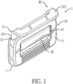
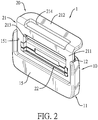
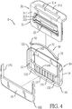
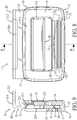
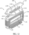
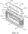
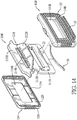
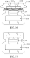
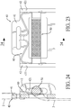
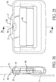
- each one of a first embodiment, a second embodiment, and a third embodiment of a webbing length adjustment device 1 in accordance with the present invention comprises an outer shell 10, 10B, an adjustment assembly 20, 20A, 20B, and an elastic member 30.
- the outer shell 10, 10B has a wall 11, 11B and a longitudinal groove 12, 12B.
- the wall 11, 11B has a first side plate 14, 14B, a second side plate 15, 15B, and a bottom plate 13, 13B.
- the first side plate 14, 14B has a first connecting hole 141, 141B formed through the first side plate 14, 14B.
- the second side plate 15, 15B is laterally opposite to the first side plate 14, 14B at a spaced interval and has a second connecting hole 151, 151B formed through the second side plate 15, 15B.
- the bottom plate 13, 13B is disposed between and is connected with the first side plate 14, 14B and the second side plate 15, 15B.
- the longitudinal groove 12, 12B is formed in the wall 11, 11B, is located between the first side plate 14, 14B and the second side plate 15,15B, is located above the bottom plate 13, 13B, communicates with the first connecting hole 141, 141B of the first side plate 14, 14B and the second connecting hole 151, 151B of the second side plate 15, 15B, and has at least one upward opening 121, 121B formed on the wall 11, 11B.
- the first side plate 14, 14B has an inner side surface facing the longitudinal groove 12, 12B and two positioning grooves 142, 142B.
- the two positioning grooves 142, 142B are formed on the inner side surface of the first side plate 14, 14B and are oppositely located beside the first connecting hole 141, 141B.
- the outer shell 10B has a lateral protrusion 16.
- the lateral protrusion 16 is formed on a bottom end of the first side plate 14B and extends outwardly and laterally.
- the lateral protrusion 16 gives more areas to a user for gripping.
- the outer shell 10 has a shell body 101 and a cover 102.
- the shell body 101 is combined to the cover 102 to form an integrated outer shell 10.
- the shell body 101 has the first side plate 14.
- the cover 102 has the second side plate 15.
- the second connecting hole 151 of the second side plate 15 is formed from a top end of the second side plate 15 and extends longitudinally.
- the second connecting hole 151 is open upwardly.
- the bottom plate 13 has a concave portion 131 and two receiving portions 132.
- the concave portion 131 is located at a middle section of the bottom plate 13 and has two side ends.
- the two receiving portions 132 are respectively formed on the two side ends of the concave portion 131.
- the outer shell 10 is an integrated element.
- the outer shell 10B has a first semi-shell 103 and a second semi-shell 104, the first semi-shell 103 is fixed with the second semi-shell 104 by means such as high-frequency welding and fastening elements.
- the first side plate 14B having the first connecting hole 141B is located at the first semi-shell 103.
- the second side plate 15B having the second connecting hole 151B is located at the second semi-shell 104.
- the second connecting hole 151B is formed on a middle section of the second side plate 15B.
- the adjustment assembly 20, 20A, 20B is disposed in and is moveable relative to the wall 11 of the outer shell 10, 10B.
- the adjustment assembly 20, 20A, 20B has an operating member 21, 21B and a sliding member 22, 22A.
- the sliding member 22, 22A is connected to the operating member 21, 21B and is moveable relative to the operating member 21, 21B.
- the operating member 21 of the adjustment assembly 20, 20A is an integrated and independent member and is made of rigid materials, such as metal.
- the operating member 21 has a longitudinal plate portion 211 and a lateral pressing plate portion 212.
- the longitudinal plate portion 211 has a first through hole 213 and a second through hole 214.
- the first through hole 213 and the second through hole 214 are formed through the longitudinal plate portion 211.
- the second through hole 214 is located above the first through hole 213.
- the longitudinal plate portion 211 is moveably disposed in the longitudinal groove 12 of the outer shell 10 and protrudes out of a top surface of the outer shell 10.
- the operating member 21 can longitudinally move relative to the outer shell 10.
- the lateral pressing plate portion 212 is formed on a top end of the longitudinal plate portion 211, is bent and extends laterally, and is located beside the first through hole 213 and the second through hole 214.
- the lateral pressing plate portion 212 is located above the first side plate 14 of the outer shell 10.
- the second through hole 214 is formed on a connecting portion between the longitudinal plate portion 211 and the lateral pressing plate portion 212.
- the outer shell 10B has a lateral protrusion 16.
- the lateral protrusion 16 is formed on a bottom end of the first side plate 14B of the wall 11B and is located below the lateral pressing plate portion 212B.
- the sliding member 22, 22A is disposed in the first through hole 213 of the operating member 21, is moveable relative to the operating member 21, and can longitudinally move relative to the outer shell 10.
- the sliding member 22, 22A has a sliding plate 221 and two sliding connecting portions 223, 223'.
- the sliding plate 221 is located at a side of the longitudinal plate portion 211 of the operating member 21, is located in the first connecting hole 141 of the first side plate 14 of the outer shell 10, is located below the lateral pressing plate portion 212, and has a side surface facing the operating member 21.
- the two sliding connecting portions 223, 223' are disposed on the side surface of the sliding plate 221 at a spaced interval and are inserted into the first through hole 213 of the operating member 21.
- the sliding member 22, 22A can longitudinally move in the longitudinal plate portion 211 of the operating member 21.
- the sliding plate 221 of the sliding member 22, 22A has a base plate portion 2211 and two side plate portions 2212.
- the base plate portion 2211 is located in the first connecting hole 141 of the first side plate 14 and has two side ends.
- the two side plate portions 2212 are respectively formed on and upwardly protruded from the two side ends of the base plate portion 2211, and are respectively inserted into the two positioning grooves 142 of the first side plate 14 for limiting a longitudinal movement distance of the sliding member 22.
- the sliding member 22 has a covering body 222.
- the covering body 222 is made of a bent metal slice or any rigid material, is wound around and fixed on the base plate portion 2211 of the sliding plate 221, and has two side ends.
- the two sliding connecting portions 223 are respectively formed on the two side ends of the covering body 222, are inserted through the first through hole 213 of the operating member 21, and extend to a side surface of the longitudinal plate portion 211 facing the second side plate 15.
- the sliding member 22 is moveable relative to the operating member 21.
- the two sliding connecting portions 223' are two protrusions, are formed on a side surface of the base plate portion 2211, and are inserted into the first through hole 213 of the operating member 21.
- the sliding member 22A is moveable relative to the operating member 21.
- the operating member 21B of the adjustment assembly 20B has the longitudinal plate portion 211B and a covering shell 210B.
- the longitudinal plate portion 211B is made of the rigid materials, such as metal.
- the longitudinal plate portion 211B is moveably disposed on the outer shell 10B and has a top section and a bottom section.
- the top section of the longitudinal plate portion 211B is disposed out of the top surface of the outer shell 10B.
- the bottom section of the longitudinal plate portion 211B is located below the top section of the longitudinal plate portion 211B and is moveably disposed in the longitudinal groove 12B of the outer shell 10B.
- the covering shell 210B is made of plastic materials.
- the covering shell 210B covers the top section of the longitudinal plate portion 211B.
- the first through hole 213B is formed through the bottom section of the longitudinal plate portion 211B.
- the second through hole 214B is formed through the top section of the longitudinal plate portion 211B and the covering shell 210B.
- the lateral pressing plate portion 212B is formed on the covering shell 210B, is located beside the second through hole 214B, and is located above the first side plate 14B of the outer shell 10B.
- the lateral protrusion 16 is formed on and laterally protrudes out of the bottom end of the first side plate 14B of the wall 11B, and is located below the lateral pressing plate portion 212B.
- the sliding members 22 in the first embodiment and the third embodiment of the webbing length adjustment device 1B are the same and can be replaced with the sliding member 22A in the second embodiment of the webbing length adjustment device 1A.
- the structure of the sliding member 22 in the third embodiment of the webbing length adjustment device 1B will not be described herein.
- the sliding member 22 is disposed in the first through hole 213B of the operating member 21B and is moveable relative to the operating member 21B.
- the operating member 21B has a central hole 215.
- the central hole 215 is formed through the longitudinal plate portion 211B and is located between the first through hole 213B and the second through hole 214B.
- the outer shell 10B has a positioning protrusion 17.
- the positioning protrusion 17 is formed on the top surface of the outer shell 10B and passes through the central hole 215 for limiting a relative movement distance between the operating member 21B and the outer shell 10B.
- the elastic member 30 can be a spring or an elastic slice.
- the elastic member 30 is disposed in the longitudinal groove 12 of the outer shell 10, 10B, and is located between the bottom plate 13 and the longitudinal plate portion 211 of the operating member 21 for giving a restoring force to the operating member 21.
- the elastic member 30 is the elastic slice and has an elastic base 31 and two end portions 32.
- the elastic base 31 is an upward arc and has two side ends and a middle section.
- the middle section is located between the side ends of the elastic base 31 and is connected to a middle of a bottom surface of the longitudinal plate portion 211, 211B of the operating member 21 for giving a restoring force to the operating member 21, 21B to move steadily.
- the bottom plate 13 of the outer shell 10 has the concave portion 131 and the two receiving portions 132 respectively formed on two side ends of the concave portion 131.
- the two end portions 32 of the elastic member 30 respectively abut against the two receiving portions 132 of the bottom plate 13.
- the first embodiment of the webbing length adjustment device 1 is applied to a seat belt system.
- a first webbing 2 of the seat belt system passes through the first through hole 213 and the second through hole 214 of the operating member 12 of the adjustment assembly 20.
- the first webbing 2 is connected to the operating member 21.
- a second webbing 3 of the seat belt system passes through the second connecting hole 151 of the second side plate 15 from the outside of the second side plate 15, passes through the first through hole 213 of the operating member 21, passes through the first connecting hole 141 of the first side plate 14 between a bottom of the sliding member 22 and the first side plate 14, curls around the sliding member 22 and returns from the first through hole 213 of the operating member 21, and passes out of the second connecting hole 151 of the second side plate 15 in sequence.
- the second webbing 3 is wound around the sliding member 22.
- the elastic member 30 gives the restoring force to the operating member 21 for pushing the operating member of the adjustment assembly 20 upwardly.
- the operating member 21 and the sliding member 22 retained in the outer shell 10 relatively clip the second webbing 3 to fix the second webbing 3.
- the third embodiment of the webbing length adjustment device 1B is applied to a seat belt system.
- the first webbing 2 of the seat belt system passes through the second through hole 214B of the operating member 21B and is connected to a top section of the operating member 21B.
- the second webbing 3 of the seat belt system passes through the second connecting hole 151B of the second side plate 15B from the outside of the second side plate 15B, passes through the first through hole 213B of the operating member 21B between the bottom of the sliding member 22 and the first side plate 14B, curls around the sliding member 22 and returns from the first through hole 213B of the operating member 21, and passes out of the second connecting hole 151B of the second side plate 15B in sequence.
- the second webbing 3 is wound around the sliding member 22.
- the elastic member 30 gives the restoring force to the operating member 21B for pushing the operating member of the adjustment assembly 20B upwardly.
- the operating member 21B and the sliding member 22 retained in the outer shell 10B relatively clip the second webbing 3 to fix the second webbing 3.
- the second webbing 3 is fixed by the webbing length adjustment device 1, 1B.
- the user can pull one free end of the second webbing 3 by a single hand without holding the operating member 21, 21B to tighten the seat belt system.
- the operating member 21, 21B and the sliding member 22 retained in the outer shell 10, 10B relatively clip the second webbing 3 to fix the second webbing 3 by the tension of the second webbing 3, friction generated between the second webbing 3 and the operating member 21, 21B, and friction generated between the second webbing 3 and the sliding member 22.
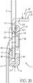
- the user For adjusting the length of the second webbing 3, with reference to Fig. 20 showing the first embodiment of the webbing length adjustment device 1, the user holds the operating member 21 by the hand and presses the lateral pressing plate portion 212 and the bottom portion of the outer shell 10.
- the lateral pressing plate portion 212 gives points of application for pressing easily.
- the operating member 21 moves relative to the sliding member 22.
- the elastic member 30 located between the operating member 21 and the bottom plate 13 of the outer shell 10 is forced to generate an elastic deformation.
- the second webbing 3 is loosened by the operating member 21 and the sliding member 22.
- the hand keeps pressing lateral pressing plate portion 212 and the bottom of the outer shell 10 to carry the webbing length adjustment device 1 to the desired position.
- the hand is released, and the elastic member 30 gives the restoring force to the operating member 21.
- the operating member 21 and the sliding member 22 relatively clip the second webbing 3 for fixing the second webbing 3.
- the second webbing 3 is fixed by the webbing length adjustment device 1 again.
- the operating member 21, 21B is disposed in the outer shell 10, 10B.
- the lateral pressing plate portion 212, 212B is formed on the top end of the operating member 21, 21B and is bent laterally.
- the lateral pressing plate portion 212, 212B of the operating member 21, 21B and the bottom portion of the outer shell 10, 10B can be held and pressed by the single hand of the user for loosening the second webbing 3.
- the lateral pressing plate portion 212, 212B of the operating member 21, 21B gives more areas for gripping and gives the points of application for pressing easily and operating conveniently.
- the lateral pressing plate portion 212, 212B is located at an outer side of the first webbing 2 and gives good points of application for pressing easily.
- the webbing length adjustment device 1, 1A, 1B provides the outer shell 10, 10B for disposing, protecting, and gripping the adjustment assembly 20, 20A, 20B.
- the elastic member 30 is an independent member and is disposed in the outer shell 10, 10B for giving the restoring force to the operating member 21, 21B of the adjustment assembly 20, 20A, 20B. Therefore, the outer shell 10, 10B is hard to damage.
Landscapes
- Engineering & Computer Science (AREA)
- Mechanical Engineering (AREA)
- Textile Engineering (AREA)
- Automotive Seat Belt Assembly (AREA)
- Buckles (AREA)
- Purses, Travelling Bags, Baskets, Or Suitcases (AREA)
Claims (14)
- Gurtbandlängen-Einstellvorrichtung, die dafür angewendet wird, mit einem ersten Gurtband (2) und mit einem zweiten Gurtband (3) eines Sicherheitsgurtsystems verbunden zu werden, und wobei die Gurtbandlängen-Einstellvorrichtung (1, 1A, 1B) umfasst:eine Außenkapsel (10, 10B), die Folgendes aufweist:eine Wand (11, 11B), die Folgendes aufweist:eine erste Seitenplatte (14, 14B) mit einem ersten Verbindungsloch (141, 141B), das durch die erste Seitenplatte (14, 14B) gebildet ist;eine zweite Seitenplatte (15, 15B), die der ersten Seitenplatte (14, 14B) in einem räumlichen Abstand seitlich gegenüberliegt und die ein zweites Verbindungsloch (151, 151B), das durch die zweite Seitenplatte (15, 15B) gebildet ist, aufweist; undeine Bodenplatte (13, 13B), die zwischen der ersten Seitenplatte (14, 14B) und der zweiten Seitenplatte (15, 15B) angeordnet und mit ihnen verbunden ist; undeine in der Wand (11, 11B) gebildete Längsnut (12, 12B), die sich zwischen der ersten Seitenplatte (14, 14B) und der zweiten Seitenplatte (15, 15B) befindet, die sich über der Bodenplatte (13, 13B) befindet, die mit dem ersten Verbindungsloch (141, 141B) der ersten Seitenplatte (14, 14B) und mit dem zweiten Verbindungsloch (151, 151B) der zweiten Seitenplatte (15, 15B) in Verbindung steht und die wenigstens eine an der Wand (11, 11B) gebildete nach oben gerichtete Öffnung (121, 121B) aufweist;eine Einstellanordnung (20, 20A, 20B), die in der Außenkapsel (10, 10B) angeordnet ist und Folgendes aufweist:ein Betätigungsglied (21, 21B), das in der Längsnut (12, 12B) der Außenkapsel (10, 10B) beweglich angeordnet ist und Folgendes aufweist:ein erstes Durchgangsloch (213, 213B), das durch das Betätigungsglied (21, 21B) gebildet ist und das sich in der Längsnut (12, 12B) der Außenkapsel (10, 10B) befindet; undeinen seitlichen Druckplattenabschnitt (212, 212B), der an dem Betätigungsglied (21, 21B) gebildet ist; undein Schiebeglied (22, 22A), das in dem ersten Durchgangsloch (213, 213B) des Betätigungsglieds (21, 21B) angeordnet ist, wobei das Betätigungsglied (21, 21B) und das Schiebeglied (22, 22A) in der Außenkapsel (10, 10B) angeordnet sind und sich relativ zueinander bewegen, wobei das zweite Gurtband (3) von einer Außenseite der Außenkapsel (10, 10B) durch das erste Durchgangsloch (213, 213B) des Betätigungsglieds (21, 21B) geht, um das Schiebeglied (22, 22A) gewunden ist und von dem ersten Durchgangsloch (213, 213B) zurückkehrt und aus der Außenkapsel (10, 10B) hinausgeht, wobei das zweite Gurtband (3) durch eine Relativbewegung zwischen dem Betätigungsglied (21, 21B) und dem Schiebeglied (22, 22A) verriegelt oder entriegelt wird; undein elastisches Glied (30), das in der Längsnut (12, 12B) der Außenkapsel (10, 10B) angeordnet ist und das sich zwischen der Bodenplatte (13, 13B) und dem Betätigungsglied (21, 21B) befindet, und dadurch gekennzeichnet, dass:das Betätigungsglied (21, 21B) Folgendes aufweist:
ein zweites Durchgangsloch (214, 214B), das durch das Betätigungsglied (21, 21B) gebildet ist und das sich über dem ersten Durchgangsloch (213, 213B) befindet, wobei das erste Gurtband (2) durch das erste Durchgangsloch (213, 213B) und durch das zweite Durchgangsloch (214, 214B) des Betätigungsglieds (21, 21B) eingeführt ist, damit es mit dem Betätigungsglied (21, 21B) verbunden ist; undsich der seitliche Druckplattenabschnitt (212, 212B) über der Außenkapsel (10, 10B) befindet und sich neben dem zweiten Durchgangsloch (214, 214B) befindet, wobei sich der seitliche Druckplattenabschnitt (212, 212B) auf einer Außenseite des ersten Gurtbands (2) befindet. - Gurtbandlängen-Einstellvorrichtung gemäß Anspruch 1, wobei das Schiebeglied (22, 22A) Folgendes aufweist:eine Schiebeplatte (221), die sich auf einer Seite des Betätigungsglieds (21, 21B) befindet, die sich in dem ersten Verbindungsloch (141, 141B) der ersten Seitenplatte (14, 14B) der Außenkapsel (10, 10B) befindet und die eine Seitenfläche aufweist, die dem Betätigungsglied (21, 21B) zugewandt ist; undzwei Schiebeverbindungsabschnitte (223), die an der Seitenfläche der Schiebeplatte (221) in einem räumlichen Abstand angeordnet sind und die in das erste Durchgangsloch (213, 213B) des Betätigungsglieds (21, 21B) eingeführt sind.
- Gurtbandlängen-Einstellvorrichtung gemäß Anspruch 2, wobei
die erste Seitenplatte (14, 14B) Folgendes aufweist:eine Innenseitenfläche, die der Längsnut (12, 12B) zugewandt ist; undzwei Positioniernuten (142), die an der Innenseitenfläche der ersten Seitenplatte (14, 14B) gebildet sind und die sich gegenüberliegend neben dem ersten Verbindungsloch (141, 141B) befinden; unddie Schiebeplatte (221) des Schiebeglieds (22, 22A) Folgendes aufweist:einen Grundplattenabschnitt (2211), der sich in dem ersten Verbindungsloch (141, 141B) der ersten Seitenplatte (14, 14B) befindet und zwei seitliche Enden aufweist; undzwei Seitenplattenabschnitte (2112), die jeweils an den zwei seitlichen Enden des Grundplattenabschnitts (2211) und nach oben davon vorstehend gebildet sind und die jeweils in die zwei Positioniernuten (142) der ersten Seitenplatte (14, 14B) eingeführt sind, um eine Längsbewegungsstrecke des Schiebeglieds (22, 22A) zu begrenzen. - Gurtbandlängen-Einstellvorrichtung gemäß Anspruch 3, wobei das Schiebeglied (22, 22A) Folgendes aufweist:
einen Abdeckkörper (222), der um den Grundplattenabschnitt (2211) der Schiebeplatte (221) gewunden und daran befestigt ist und der Folgendes aufweist:zwei seitliche Enden; unddie zwei Schiebeverbindungsabschnitte (223), jeweils an den zwei seitlichen Enden des Abdeckkörpers (222) gebildet sind und die durch das erste Durchgangsloch (213, 213B) des Betätigungsglieds (21, 21B) eingeführt sind. - Gurtbandlängen-Einstellvorrichtung gemäß Anspruch 3, wobei die zwei Schiebeverbindungsabschnitte (223) zwei Vorsprünge sind, an einer Seitenfläche des Grundplattenabschnitts (2211) gebildet sind und in das erste Durchgangsloch (213, 213B) des Betätigungsglieds (21, 21B) eingeführt sind.
- Gurtbandlängen-Einstellvorrichtung gemäß einem der Ansprüche 1 bis 5, wobei die Außenkapsel (10, 10B) einen seitlichen Vorsprung (16) aufweist, der an einem unteren Ende der ersten Seitenplatte (14, 14B) der Wand gebildet ist und der sich unter dem seitlichen Druckplattenabschnitt (212, 212B) befindet.
- Gurtbandlängen-Einstellvorrichtung gemäß einem der Ansprüche 1 bis 5, wobei das elastische Glied (30) ein elastischer Streifen ist, in der Längsnut (12, 12B) der Außenkapsel (10, 10B) angeordnet ist und Folgendes aufweist:einen elastischen Hauptteil (31), der ein nach oben gerichteter Bogen ist und Folgendes aufweist:zwei seitliche Enden; undeinen mittleren Teil, der sich zwischen den zwei seitlichen Enden des elastischen Hauptteils (31) befindet und der mit einer Mitte einer Bodenoberfläche des Betätigungsglieds (21, 21B) verbunden ist; undzwei Endabschnitte (32), die jeweils an den zwei seitlichen Enden des elastischen Hauptteils (31) gebildet sind und an der Bodenplatte (13, 13B) anliegen.
- Gurtbandlängen-Einstellvorrichtung gemäß einem der Ansprüche 1 bis 5, wobei
das Betätigungsglied (21, 21B) einen Längsplattenabschnitt (211, 211B) aufweist, der in der Längsnut (12, 12B) der Außenkapsel (10, 10B) beweglich angeordnet ist und der ein oberes Ende aufweist;
der seitliche Druckplattenabschnitt (212, 212B) in das obere Ende des Längsplattenabschnitts (211, 211B) integriert ist und seitlich gebogen ist;
das erste Durchgangsloch (213, 213B) durch den Längsplattenabschnitt (211, 211B) gebildet ist; und
das zweite Durchgangsloch (214, 214B) benachbart zu dem seitlichen Druckplattenabschnitt (212, 212B) durch den Längsplattenabschnitt (211, 211B) gebildet ist. - Gurtbandlängen-Einstellvorrichtung gemäß Anspruch 8, wobei die Wand (11, 11B) einen seitlichen Vorsprung (16) aufweist, der an einem unteren Ende der ersten Seitenplatte (14, 14B) der Wand (11, 11B) gebildet ist und sich unter dem seitlichen Druckplattenabschnitt (212, 212B) befindet.
- Gurtbandlängen-Einstellvorrichtung gemäß Anspruch 8, wobei das zweite Verbindungsloch (151, 151B) der zweiten Seitenplatte (15, 15B) von einem oberen Ende der zweiten Seitenplatte (15, 15B) gebildet ist und in Längsrichtung verläuft.
- Gurtbandlängen-Einstellvorrichtung gemäß Anspruch 8, wobei das elastische Glied (30) ein elastischer Streifen ist, in der Längsnut (12, 12B) der Außenkapsel (10, 10B) angeordnet ist und Folgendes aufweist:einen elastischen Hauptteil (31), der nach oben gebogen ist und Folgendes aufweist:zwei seitliche Enden; undeinen mittleren Teil, der sich zwischen den zwei seitlichen Enden des elastischen Hauptteils (31) befindet und mit einer Mitte einer unteren Oberfläche des Betätigungsglieds (21, 21B) verbunden ist; undzwei Endabschnitte (32), die jeweils an den zwei seitlichen Enden des elastischen Hauptteils (31) gebildet sind und an der Bodenplatte (13, 13B) anliegen.
- Gurtbandlängen-Einstellvorrichtung gemäß Anspruch 1, wobei das Betätigungsglied (21, 21B) Folgendes aufweist:einen Längsplattenabschnitt (211, 211B), der an der Außenkapsel (10, 10B) beweglich angeordnet ist und Folgendes aufweist:einen oberen Teil, der aus der Außenkapsel (10, 10B) heraus angeordnet ist; undeinen unteren Teil, der sich beweglich unter dem oberen Teil des Längsplattenabschnitts (211, 211B) befindet und der in der Längsnut (12, 12B) der Außenkapsel (10, 10B) angeordnet ist;eine Abdeckkapsel (210B), die den oberen Teil des Längsplattenabschnitts (211, 211B) bedeckt und die sich über der Außenkapsel (10, 10B) befindet;dass das erste Durchgangsloch (213, 213B) durch den unteren Teil des Längsplattenabschnitts (211, 211B) gebildet ist;dass das zweite Durchgangsloch (214, 214B) durch den oberen Teil des Längsplattenabschnitts (211, 211B) und durch die Abdeckkapsel (210B) gebildet ist; unddass der seitliche Druckplattenabschnitt (212, 212B) an der Abdeckkapsel (210B) gebildet ist.
- Gurtbandlängen-Einstellvorrichtung gemäß Anspruch 12, wobei die Wand (11, 11B) einen seitlichen Vorsprung (16) aufweist, der an einem unteren Ende der ersten Seitenplatte (14, 14B) der Wand (11, 11B) gebildet ist und der sich unter dem seitlichen Druckplattenabschnitt (212, 212B) befindet.
- Gurtbandlängen-Einstellvorrichtung gemäß Anspruch 12, wobei das elastische Glied (30) ein elastischer Streifen ist, in der Längsnut (12, 12B) der Außenkapsel (10, 10B) angeordnet ist und Folgendes aufweist:einen elastischen Hauptteil (31), der nach oben gebogen ist und Folgendes aufweist:zwei seitliche Enden; undeinen mittleren Teil, der sich zwischen den zwei seitlichen Enden des elastischen Hauptteils (31) befindet und der mit einer Mitte einer unteren Oberfläche des Betätigungsglieds (21, 21B) verbunden ist; undzwei Endabschnitte (32), die jeweils an den zwei seitlichen Enden des elastischen Hauptteils (31) gebildet sind und an der Bodenplatte (13, 13B) anliegen.
Applications Claiming Priority (1)
| Application Number | Priority Date | Filing Date | Title |
|---|---|---|---|
| TW108108636A TWI694016B (zh) | 2019-03-14 | 2019-03-14 | 織帶長度調整裝置 |
Publications (2)
| Publication Number | Publication Date |
|---|---|
| EP3708440A1 EP3708440A1 (de) | 2020-09-16 |
| EP3708440B1 true EP3708440B1 (de) | 2021-06-23 |
Family
ID=69779986
Family Applications (1)
| Application Number | Title | Priority Date | Filing Date |
|---|---|---|---|
| EP20161423.7A Active EP3708440B1 (de) | 2019-03-14 | 2020-03-06 | Vorrichtung zur einstellung der gurtbandlänge |
Country Status (6)
| Country | Link |
|---|---|
| US (1) | US11338766B2 (de) |
| EP (1) | EP3708440B1 (de) |
| JP (1) | JP6883358B2 (de) |
| DK (1) | DK3708440T3 (de) |
| ES (1) | ES2894325T3 (de) |
| TW (1) | TWI694016B (de) |
Families Citing this family (8)
| Publication number | Priority date | Publication date | Assignee | Title |
|---|---|---|---|---|
| US11584336B2 (en) * | 2020-10-30 | 2023-02-21 | Richard H. Galloway | Seat belt accessory and method of use |
| WO2022187825A1 (en) * | 2021-03-02 | 2022-09-09 | Indiana Mills & Manufacturing, Inc. | Lever release mid-belt adjuster |
| US20240101064A1 (en) * | 2022-08-24 | 2024-03-28 | Ohio State Innovation Foundation | Bayonet coupler and vehicle occupant restraint system for use therein |
| KR102543219B1 (ko) * | 2022-12-08 | 2023-06-14 | 공주대학교 산학협력단 | 차량 내 탑승자 가슴 착용 안전벨트 |
| CN219182969U (zh) * | 2023-02-07 | 2023-06-16 | 宁波聚关防坠落装备有限公司 | 一种安全带调节扣 |
| US20250009075A1 (en) * | 2023-07-06 | 2025-01-09 | Austere Manufacturing, LLC | Sliding Buckle with Locking Feature |
| TWI888919B (zh) * | 2023-09-14 | 2025-07-01 | 宏霖工業股份有限公司 | 織帶高度調整裝置 |
| TWI892293B (zh) * | 2023-11-08 | 2025-08-01 | 宏霖工業股份有限公司 | 織帶高度調整器及織帶高度調整裝置 |
Family Cites Families (17)
| Publication number | Priority date | Publication date | Assignee | Title |
|---|---|---|---|---|
| US3293713A (en) * | 1964-11-18 | 1966-12-27 | Koch & Sons Inc H | Adjustable strap connector |
| US3414947A (en) * | 1967-07-03 | 1968-12-10 | Holmberg Gote Eskil Yngve | Strap fasteners |
| US3591900A (en) * | 1969-06-30 | 1971-07-13 | Sauna International Inc | Belt adjuster |
| US3999254A (en) * | 1975-05-21 | 1976-12-28 | Satron, Inc. | Two-piece locking buckle |
| SE393523B (sv) | 1975-11-17 | 1977-05-16 | Bengtsson Sigurd W | Sjelvlasande bandspenne |
| US4962572A (en) * | 1989-02-22 | 1990-10-16 | Trw Vehicle Safety Systems Inc. | Tongue assembly |
| DE9111299U1 (de) | 1991-09-11 | 1991-10-31 | van Riesen & Co, 2080 Pinneberg | Schnellversteller für ein Gurtband-Rückhaltesystem |
| SE470433B (sv) | 1992-08-06 | 1994-03-07 | Holmbergs Fab Ab Brdr | Anordning för justerbar infästning av ett band |
| KR950004963Y1 (ko) | 1992-12-03 | 1995-06-20 | 서삼암 | 안전장치를 한 끈고리 |
| US6665912B2 (en) | 2002-04-03 | 2003-12-23 | Cosco Management, Inc. | Web adjuster |
| TWM338786U (en) * | 2008-04-11 | 2008-08-21 | Wen-Yuan Wu | Seat belt adjuster |
| DE202008006576U1 (de) | 2008-05-14 | 2008-07-24 | Wu, Wen-Yuan, Pusin | Versteller für Sicherheitsgurt |
| CN104417485B (zh) | 2013-08-23 | 2016-12-07 | 宋谊超 | 汽车安全带舒适度调节器 |
| CN204415321U (zh) | 2015-02-09 | 2015-06-24 | 郭壁蓉 | 一种织带调整器 |
| US10611334B2 (en) | 2017-02-07 | 2020-04-07 | Shield Restraint Systems, Inc. | Web adjuster |
| KR101972300B1 (ko) * | 2017-07-26 | 2019-04-26 | 계명대학교 산학협력단 | 안전벨트용 버클 길이 조절장치 |
| TWI640444B (zh) * | 2017-11-20 | 2018-11-11 | 王亮雄 | 織帶調整裝置 |
-
2019
- 2019-03-14 TW TW108108636A patent/TWI694016B/zh active
-
2020
- 2020-02-25 US US16/801,030 patent/US11338766B2/en active Active
- 2020-03-06 ES ES20161423T patent/ES2894325T3/es active Active
- 2020-03-06 DK DK20161423.7T patent/DK3708440T3/da active
- 2020-03-06 EP EP20161423.7A patent/EP3708440B1/de active Active
- 2020-03-06 JP JP2020038468A patent/JP6883358B2/ja active Active
Also Published As
| Publication number | Publication date |
|---|---|
| US20200290557A1 (en) | 2020-09-17 |
| JP6883358B2 (ja) | 2021-06-09 |
| TW202033391A (zh) | 2020-09-16 |
| JP2020147277A (ja) | 2020-09-17 |
| DK3708440T3 (da) | 2021-07-12 |
| EP3708440A1 (de) | 2020-09-16 |
| US11338766B2 (en) | 2022-05-24 |
| ES2894325T3 (es) | 2022-02-14 |
| TWI694016B (zh) | 2020-05-21 |
Similar Documents
| Publication | Publication Date | Title |
|---|---|---|
| EP3708440B1 (de) | Vorrichtung zur einstellung der gurtbandlänge | |
| US6682144B2 (en) | Support with adjustable arch, especially a lumbar support for any type of seat or bed | |
| US5311653A (en) | Web adjuster for plastic coated web | |
| US6868585B2 (en) | Web adjuster device | |
| US6073901A (en) | Device for supporting objects | |
| US20020050707A1 (en) | Buckle device | |
| KR100714560B1 (ko) | 좌석 벨트 시스템의 웨브 가이드용 높이 조절 장치 | |
| US6941657B2 (en) | Nail clippers | |
| CA2331948A1 (en) | Ring binder having actuating lever with cushion member | |
| JPH02147455A (ja) | 安全装置用のタング組立体 | |
| US5427412A (en) | Removable web guide assembly | |
| CN220155683U (zh) | 电池包 | |
| KR0129421B1 (ko) | 압박감을 해소하는 자동차용 시트벨트의 텅 | |
| EP4552932B1 (de) | Gurtbandhöhenanpassungseinheit und gurtbandhöhenanpassungsvorrichtung | |
| US10183647B2 (en) | Vehicle seatbelt buckle assembly and method | |
| KR100461829B1 (ko) | 차량 시트벨트 텅의 위치조절장치 | |
| JP7766824B2 (ja) | ロッキングタング | |
| JP6541224B2 (ja) | 車両用シート | |
| KR0126085Y1 (ko) | 차량용 시트벨트의 버클구조 | |
| JP7525880B2 (ja) | シート | |
| JP2569266Y2 (ja) | シートのベルトガイド構造 | |
| JPH0228126Y2 (de) | ||
| CN117774624A (zh) | 轴杆接收装置 | |
| JPH0125087Y2 (de) | ||
| KR890004576Y1 (ko) | 안전 벨트의 조임 방지장치 |
Legal Events
| Date | Code | Title | Description |
|---|---|---|---|
| PUAI | Public reference made under article 153(3) epc to a published international application that has entered the european phase |
Free format text: ORIGINAL CODE: 0009012 |
|
| STAA | Information on the status of an ep patent application or granted ep patent |
Free format text: STATUS: THE APPLICATION HAS BEEN PUBLISHED |
|
| AK | Designated contracting states |
Kind code of ref document: A1 Designated state(s): AL AT BE BG CH CY CZ DE DK EE ES FI FR GB GR HR HU IE IS IT LI LT LU LV MC MK MT NL NO PL PT RO RS SE SI SK SM TR |
|
| AX | Request for extension of the european patent |
Extension state: BA ME |
|
| STAA | Information on the status of an ep patent application or granted ep patent |
Free format text: STATUS: REQUEST FOR EXAMINATION WAS MADE |
|
| 17P | Request for examination filed |
Effective date: 20201127 |
|
| RBV | Designated contracting states (corrected) |
Designated state(s): AL AT BE BG CH CY CZ DE DK EE ES FI FR GB GR HR HU IE IS IT LI LT LU LV MC MK MT NL NO PL PT RO RS SE SI SK SM TR |
|
| GRAP | Despatch of communication of intention to grant a patent |
Free format text: ORIGINAL CODE: EPIDOSNIGR1 |
|
| STAA | Information on the status of an ep patent application or granted ep patent |
Free format text: STATUS: GRANT OF PATENT IS INTENDED |
|
| INTG | Intention to grant announced |
Effective date: 20210118 |
|
| GRAS | Grant fee paid |
Free format text: ORIGINAL CODE: EPIDOSNIGR3 |
|
| GRAA | (expected) grant |
Free format text: ORIGINAL CODE: 0009210 |
|
| STAA | Information on the status of an ep patent application or granted ep patent |
Free format text: STATUS: THE PATENT HAS BEEN GRANTED |
|
| AK | Designated contracting states |
Kind code of ref document: B1 Designated state(s): AL AT BE BG CH CY CZ DE DK EE ES FI FR GB GR HR HU IE IS IT LI LT LU LV MC MK MT NL NO PL PT RO RS SE SI SK SM TR |
|
| REG | Reference to a national code |
Ref country code: GB Ref legal event code: FG4D |
|
| REG | Reference to a national code |
Ref country code: CH Ref legal event code: EP |
|
| REG | Reference to a national code |
Ref country code: DK Ref legal event code: T3 Effective date: 20210706 |
|
| REG | Reference to a national code |
Ref country code: DE Ref legal event code: R096 Ref document number: 602020000180 Country of ref document: DE Ref country code: AT Ref legal event code: REF Ref document number: 1404056 Country of ref document: AT Kind code of ref document: T Effective date: 20210715 |
|
| REG | Reference to a national code |
Ref country code: SE Ref legal event code: TRGR |
|
| REG | Reference to a national code |
Ref country code: IE Ref legal event code: FG4D |
|
| REG | Reference to a national code |
Ref country code: NL Ref legal event code: FP |
|
| REG | Reference to a national code |
Ref country code: LT Ref legal event code: MG9D |
|
| PG25 | Lapsed in a contracting state [announced via postgrant information from national office to epo] |
Ref country code: FI Free format text: LAPSE BECAUSE OF FAILURE TO SUBMIT A TRANSLATION OF THE DESCRIPTION OR TO PAY THE FEE WITHIN THE PRESCRIBED TIME-LIMIT Effective date: 20210623 Ref country code: LT Free format text: LAPSE BECAUSE OF FAILURE TO SUBMIT A TRANSLATION OF THE DESCRIPTION OR TO PAY THE FEE WITHIN THE PRESCRIBED TIME-LIMIT Effective date: 20210623 Ref country code: HR Free format text: LAPSE BECAUSE OF FAILURE TO SUBMIT A TRANSLATION OF THE DESCRIPTION OR TO PAY THE FEE WITHIN THE PRESCRIBED TIME-LIMIT Effective date: 20210623 Ref country code: BG Free format text: LAPSE BECAUSE OF FAILURE TO SUBMIT A TRANSLATION OF THE DESCRIPTION OR TO PAY THE FEE WITHIN THE PRESCRIBED TIME-LIMIT Effective date: 20210923 |
|
| REG | Reference to a national code |
Ref country code: AT Ref legal event code: MK05 Ref document number: 1404056 Country of ref document: AT Kind code of ref document: T Effective date: 20210623 |
|
| PG25 | Lapsed in a contracting state [announced via postgrant information from national office to epo] |
Ref country code: GR Free format text: LAPSE BECAUSE OF FAILURE TO SUBMIT A TRANSLATION OF THE DESCRIPTION OR TO PAY THE FEE WITHIN THE PRESCRIBED TIME-LIMIT Effective date: 20210924 Ref country code: RS Free format text: LAPSE BECAUSE OF FAILURE TO SUBMIT A TRANSLATION OF THE DESCRIPTION OR TO PAY THE FEE WITHIN THE PRESCRIBED TIME-LIMIT Effective date: 20210623 Ref country code: LV Free format text: LAPSE BECAUSE OF FAILURE TO SUBMIT A TRANSLATION OF THE DESCRIPTION OR TO PAY THE FEE WITHIN THE PRESCRIBED TIME-LIMIT Effective date: 20210623 Ref country code: NO Free format text: LAPSE BECAUSE OF FAILURE TO SUBMIT A TRANSLATION OF THE DESCRIPTION OR TO PAY THE FEE WITHIN THE PRESCRIBED TIME-LIMIT Effective date: 20210923 |
|
| PG25 | Lapsed in a contracting state [announced via postgrant information from national office to epo] |
Ref country code: AT Free format text: LAPSE BECAUSE OF FAILURE TO SUBMIT A TRANSLATION OF THE DESCRIPTION OR TO PAY THE FEE WITHIN THE PRESCRIBED TIME-LIMIT Effective date: 20210623 Ref country code: SM Free format text: LAPSE BECAUSE OF FAILURE TO SUBMIT A TRANSLATION OF THE DESCRIPTION OR TO PAY THE FEE WITHIN THE PRESCRIBED TIME-LIMIT Effective date: 20210623 Ref country code: RO Free format text: LAPSE BECAUSE OF FAILURE TO SUBMIT A TRANSLATION OF THE DESCRIPTION OR TO PAY THE FEE WITHIN THE PRESCRIBED TIME-LIMIT Effective date: 20210623 Ref country code: PT Free format text: LAPSE BECAUSE OF FAILURE TO SUBMIT A TRANSLATION OF THE DESCRIPTION OR TO PAY THE FEE WITHIN THE PRESCRIBED TIME-LIMIT Effective date: 20211025 Ref country code: EE Free format text: LAPSE BECAUSE OF FAILURE TO SUBMIT A TRANSLATION OF THE DESCRIPTION OR TO PAY THE FEE WITHIN THE PRESCRIBED TIME-LIMIT Effective date: 20210623 Ref country code: SK Free format text: LAPSE BECAUSE OF FAILURE TO SUBMIT A TRANSLATION OF THE DESCRIPTION OR TO PAY THE FEE WITHIN THE PRESCRIBED TIME-LIMIT Effective date: 20210623 |
|
| REG | Reference to a national code |
Ref country code: ES Ref legal event code: FG2A Ref document number: 2894325 Country of ref document: ES Kind code of ref document: T3 Effective date: 20220214 |
|
| PG25 | Lapsed in a contracting state [announced via postgrant information from national office to epo] |
Ref country code: PL Free format text: LAPSE BECAUSE OF FAILURE TO SUBMIT A TRANSLATION OF THE DESCRIPTION OR TO PAY THE FEE WITHIN THE PRESCRIBED TIME-LIMIT Effective date: 20210623 |
|
| REG | Reference to a national code |
Ref country code: DE Ref legal event code: R097 Ref document number: 602020000180 Country of ref document: DE |
|
| PLBE | No opposition filed within time limit |
Free format text: ORIGINAL CODE: 0009261 |
|
| STAA | Information on the status of an ep patent application or granted ep patent |
Free format text: STATUS: NO OPPOSITION FILED WITHIN TIME LIMIT |
|
| 26N | No opposition filed |
Effective date: 20220324 |
|
| PG25 | Lapsed in a contracting state [announced via postgrant information from national office to epo] |
Ref country code: AL Free format text: LAPSE BECAUSE OF FAILURE TO SUBMIT A TRANSLATION OF THE DESCRIPTION OR TO PAY THE FEE WITHIN THE PRESCRIBED TIME-LIMIT Effective date: 20210623 |
|
| PG25 | Lapsed in a contracting state [announced via postgrant information from national office to epo] |
Ref country code: MC Free format text: LAPSE BECAUSE OF FAILURE TO SUBMIT A TRANSLATION OF THE DESCRIPTION OR TO PAY THE FEE WITHIN THE PRESCRIBED TIME-LIMIT Effective date: 20210623 |
|
| REG | Reference to a national code |
Ref country code: BE Ref legal event code: MM Effective date: 20220331 |
|
| PG25 | Lapsed in a contracting state [announced via postgrant information from national office to epo] |
Ref country code: LU Free format text: LAPSE BECAUSE OF NON-PAYMENT OF DUE FEES Effective date: 20220306 Ref country code: IE Free format text: LAPSE BECAUSE OF NON-PAYMENT OF DUE FEES Effective date: 20220306 |
|
| PG25 | Lapsed in a contracting state [announced via postgrant information from national office to epo] |
Ref country code: BE Free format text: LAPSE BECAUSE OF NON-PAYMENT OF DUE FEES Effective date: 20220331 |
|
| PGFP | Annual fee paid to national office [announced via postgrant information from national office to epo] |
Ref country code: FR Payment date: 20230111 Year of fee payment: 4 Ref country code: CZ Payment date: 20230227 Year of fee payment: 4 |
|
| PGFP | Annual fee paid to national office [announced via postgrant information from national office to epo] |
Ref country code: SE Payment date: 20230314 Year of fee payment: 4 |
|
| PGFP | Annual fee paid to national office [announced via postgrant information from national office to epo] |
Ref country code: NL Payment date: 20230326 Year of fee payment: 4 |
|
| REG | Reference to a national code |
Ref country code: CH Ref legal event code: PL |
|
| PG25 | Lapsed in a contracting state [announced via postgrant information from national office to epo] |
Ref country code: LI Free format text: LAPSE BECAUSE OF NON-PAYMENT OF DUE FEES Effective date: 20230331 Ref country code: CH Free format text: LAPSE BECAUSE OF NON-PAYMENT OF DUE FEES Effective date: 20230331 |
|
| PG25 | Lapsed in a contracting state [announced via postgrant information from national office to epo] |
Ref country code: MK Free format text: LAPSE BECAUSE OF FAILURE TO SUBMIT A TRANSLATION OF THE DESCRIPTION OR TO PAY THE FEE WITHIN THE PRESCRIBED TIME-LIMIT Effective date: 20210623 Ref country code: CY Free format text: LAPSE BECAUSE OF FAILURE TO SUBMIT A TRANSLATION OF THE DESCRIPTION OR TO PAY THE FEE WITHIN THE PRESCRIBED TIME-LIMIT Effective date: 20210623 |
|
| PG25 | Lapsed in a contracting state [announced via postgrant information from national office to epo] |
Ref country code: HU Free format text: LAPSE BECAUSE OF FAILURE TO SUBMIT A TRANSLATION OF THE DESCRIPTION OR TO PAY THE FEE WITHIN THE PRESCRIBED TIME-LIMIT; INVALID AB INITIO Effective date: 20200306 |
|
| PGFP | Annual fee paid to national office [announced via postgrant information from national office to epo] |
Ref country code: DK Payment date: 20240321 Year of fee payment: 5 |
|
| PG25 | Lapsed in a contracting state [announced via postgrant information from national office to epo] |
Ref country code: MT Free format text: LAPSE BECAUSE OF FAILURE TO SUBMIT A TRANSLATION OF THE DESCRIPTION OR TO PAY THE FEE WITHIN THE PRESCRIBED TIME-LIMIT Effective date: 20210623 |
|
| PG25 | Lapsed in a contracting state [announced via postgrant information from national office to epo] |
Ref country code: CZ Free format text: LAPSE BECAUSE OF NON-PAYMENT OF DUE FEES Effective date: 20240306 |
|
| REG | Reference to a national code |
Ref country code: SE Ref legal event code: EUG |
|
| PG25 | Lapsed in a contracting state [announced via postgrant information from national office to epo] |
Ref country code: CZ Free format text: LAPSE BECAUSE OF NON-PAYMENT OF DUE FEES Effective date: 20240306 |
|
| REG | Reference to a national code |
Ref country code: NL Ref legal event code: MM Effective date: 20240401 |
|
| PG25 | Lapsed in a contracting state [announced via postgrant information from national office to epo] |
Ref country code: NL Free format text: LAPSE BECAUSE OF NON-PAYMENT OF DUE FEES Effective date: 20240401 |
|
| PG25 | Lapsed in a contracting state [announced via postgrant information from national office to epo] |
Ref country code: NL Free format text: LAPSE BECAUSE OF NON-PAYMENT OF DUE FEES Effective date: 20240401 |
|
| PG25 | Lapsed in a contracting state [announced via postgrant information from national office to epo] |
Ref country code: FR Free format text: LAPSE BECAUSE OF NON-PAYMENT OF DUE FEES Effective date: 20240331 |
|
| PG25 | Lapsed in a contracting state [announced via postgrant information from national office to epo] |
Ref country code: FR Free format text: LAPSE BECAUSE OF NON-PAYMENT OF DUE FEES Effective date: 20240331 |
|
| PGFP | Annual fee paid to national office [announced via postgrant information from national office to epo] |
Ref country code: ES Payment date: 20250606 Year of fee payment: 6 |
|
| PG25 | Lapsed in a contracting state [announced via postgrant information from national office to epo] |
Ref country code: SE Free format text: LAPSE BECAUSE OF NON-PAYMENT OF DUE FEES Effective date: 20240307 |
|
| REG | Reference to a national code |
Ref country code: DK Ref legal event code: EBP Effective date: 20250331 |
|
| PG25 | Lapsed in a contracting state [announced via postgrant information from national office to epo] |
Ref country code: TR Free format text: LAPSE BECAUSE OF FAILURE TO SUBMIT A TRANSLATION OF THE DESCRIPTION OR TO PAY THE FEE WITHIN THE PRESCRIBED TIME-LIMIT Effective date: 20210623 |
|
| PGFP | Annual fee paid to national office [announced via postgrant information from national office to epo] |
Ref country code: GB Payment date: 20260330 Year of fee payment: 7 |
|
| PG25 | Lapsed in a contracting state [announced via postgrant information from national office to epo] |
Ref country code: DK Free format text: LAPSE BECAUSE OF NON-PAYMENT OF DUE FEES Effective date: 20250331 |
|
| PGFP | Annual fee paid to national office [announced via postgrant information from national office to epo] |
Ref country code: DE Payment date: 20260121 Year of fee payment: 7 |
|
| PGFP | Annual fee paid to national office [announced via postgrant information from national office to epo] |
Ref country code: IT Payment date: 20260116 Year of fee payment: 7 |