EP3708247A1 - Mélange non invasif de liquides - Google Patents
Mélange non invasif de liquides Download PDFInfo
- Publication number
- EP3708247A1 EP3708247A1 EP19162758.7A EP19162758A EP3708247A1 EP 3708247 A1 EP3708247 A1 EP 3708247A1 EP 19162758 A EP19162758 A EP 19162758A EP 3708247 A1 EP3708247 A1 EP 3708247A1
- Authority
- EP
- European Patent Office
- Prior art keywords
- acoustic
- fluid
- flow
- transducers
- container
- Prior art date
- Legal status (The legal status is an assumption and is not a legal conclusion. Google has not performed a legal analysis and makes no representation as to the accuracy of the status listed.)
- Withdrawn
Links
Images


Classifications
-
- B—PERFORMING OPERATIONS; TRANSPORTING
- B01—PHYSICAL OR CHEMICAL PROCESSES OR APPARATUS IN GENERAL
- B01F—MIXING, e.g. DISSOLVING, EMULSIFYING OR DISPERSING
- B01F31/00—Mixers with shaking, oscillating, or vibrating mechanisms
- B01F31/80—Mixing by means of high-frequency vibrations above one kHz, e.g. ultrasonic vibrations
- B01F31/86—Mixing by means of high-frequency vibrations above one kHz, e.g. ultrasonic vibrations with vibration of the receptacle or part of it
-
- B—PERFORMING OPERATIONS; TRANSPORTING
- B01—PHYSICAL OR CHEMICAL PROCESSES OR APPARATUS IN GENERAL
- B01F—MIXING, e.g. DISSOLVING, EMULSIFYING OR DISPERSING
- B01F31/00—Mixers with shaking, oscillating, or vibrating mechanisms
- B01F31/80—Mixing by means of high-frequency vibrations above one kHz, e.g. ultrasonic vibrations
- B01F31/89—Methodical aspects; Controlling
-
- B—PERFORMING OPERATIONS; TRANSPORTING
- B01—PHYSICAL OR CHEMICAL PROCESSES OR APPARATUS IN GENERAL
- B01F—MIXING, e.g. DISSOLVING, EMULSIFYING OR DISPERSING
- B01F35/00—Accessories for mixers; Auxiliary operations or auxiliary devices; Parts or details of general application
- B01F35/20—Measuring; Control or regulation
- B01F35/21—Measuring
- B01F35/213—Measuring of the properties of the mixtures, e.g. temperature, density or colour
-
- B—PERFORMING OPERATIONS; TRANSPORTING
- B01—PHYSICAL OR CHEMICAL PROCESSES OR APPARATUS IN GENERAL
- B01F—MIXING, e.g. DISSOLVING, EMULSIFYING OR DISPERSING
- B01F35/00—Accessories for mixers; Auxiliary operations or auxiliary devices; Parts or details of general application
- B01F35/20—Measuring; Control or regulation
- B01F35/22—Control or regulation
- B01F35/2201—Control or regulation characterised by the type of control technique used
- B01F35/2209—Controlling the mixing process as a whole, i.e. involving a complete monitoring and controlling of the mixing process during the whole mixing cycle
-
- B—PERFORMING OPERATIONS; TRANSPORTING
- B01—PHYSICAL OR CHEMICAL PROCESSES OR APPARATUS IN GENERAL
- B01F—MIXING, e.g. DISSOLVING, EMULSIFYING OR DISPERSING
- B01F35/00—Accessories for mixers; Auxiliary operations or auxiliary devices; Parts or details of general application
- B01F35/20—Measuring; Control or regulation
- B01F35/22—Control or regulation
- B01F35/221—Control or regulation of operational parameters, e.g. level of material in the mixer, temperature or pressure
- B01F35/2214—Speed during the operation
-
- B—PERFORMING OPERATIONS; TRANSPORTING
- B01—PHYSICAL OR CHEMICAL PROCESSES OR APPARATUS IN GENERAL
- B01F—MIXING, e.g. DISSOLVING, EMULSIFYING OR DISPERSING
- B01F2101/00—Mixing characterised by the nature of the mixed materials or by the application field
- B01F2101/06—Mixing of food ingredients
- B01F2101/07—Mixing ingredients into milk or cream, e.g. aerating
Definitions
- the present disclosure relates to mixing of fluids, e.g. liquids such as milk.
- dispersions, suspensions and emulsions need to be mixed or kept mixed. Often there is a strong driver for hygiene or sterility to maximize product shelf life.
- traditional mixing involves the insertion of a component (e.g. impeller) into the dispersion, suspension, or emulsion to facilitate the mixing.
- a component e.g. impeller
- cleaning may involve labor and energy costs each time cleaning is performed. So cleaning is an important part of the costs in for example the food industry such as dairy products.
- Ultrasonic cleaning baths use ultrasound to clean/mix/increase chemical reactions. However, these are typically based on high power ultrasound -with high intensities only located at a small defined spot-where the operating principle is dominated by cavitation and locally induced temperature increases. Applications of ultrasonic mixing/sorting may also occur in microfluidic setups. Typically, standing waves are used which are relatively easy to realize in microfluidic setups but infeasible for larger setups. Unfortunately, the known ultrasound based mixing may be unsuitable for use with easily damaged liquids, e.g. dispersions and emulsions. For many liquids there is an upper allowable limit for the peak liquid velocities or the induced shear stresses. For example, for milk an upper limit can be determined by the breaking up of protein-fat structure at high shear stress. But staying below the upper limit may result in insufficient mixing.
- a mixing container with a container wall can be used for holding the fluid.
- One or more acoustic transducers can be arranged on the container wall.
- the acoustic transducers may be configured to generate respective acoustic waves directed into the fluid. This may cause a respective flow pattern in the fluid (acoustic streaming).
- a flow pattern can be described by the respective flow directions and/or flow velocities of the fluid at one or more positions in the mixing container.
- mixing is achieved by a flow carrying the fluid and/or particles therein throughout the container.
- the one or more acoustic transducers are controlled to automatically switch between the generation of different acoustic waves. This may cause switching between different flow patterns to improve the fluid mixing without having to increase actuation power.
- a fixed or steady state flow pattern may develop, e.g. wherein the flow direction and velocity at positions in the fluid no longer changes.
- laminar flows may develop in which minimal mixing takes place.
- a fixed flow pattern may include regions where the fluid remains stagnant.
- Different flow patterns may be formed, e.g., by switching the flow direction and/or flow velocity at one or more positions, preferably throughout the container.
- switching between different flows may disrupt laminar flows and/or stagnant regions in the container, e.g. create vortices which can improve mixing performance. So, instead of, e.g., increasing power to the transducers (which may damage the fluid by excessive flow/shearing), mixing efficiency may be improved by switching different mixing modes without damaging the fluid.
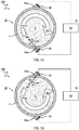
- FIGs 1A and 1B illustrate aspects described herein embodied as an apparatus 100 for mixing a fluid F.
- the apparatus 100 comprises a mixing container 10 with container walls 11 for holding the fluid F.
- the apparatus typically has at least one transducer arranged on the container wall 11 for mixing the fluid F.
- a plurality of acoustic transducers 21,22 are arranged on the container wall 11.
- the one or more acoustic transducers 21,22 are configured to generate respective acoustic waves W1,W2 directed into the fluid F for causing a respective flow pattern F1,F2 in the fluid F, preferably by acoustic streaming.
- aspects described herein may also be embodied as a method for mixing the fluid F.
- the method comprises holding the fluid F in a mixing container 10 and generating respective acoustic waves W1,W2 directed into the fluid F for causing a respective flow pattern F1,F2 in the fluid F by acoustic streaming.
- a controller 15 configured to control the one or more acoustic transducers 21,22.
- the controller is configured (e.g. programmed) to automatically switch between generation of different acoustic waves W1,W2. This may cause switching between different flow patterns F1,F2 to improve the fluid mixing.
- the method may also comprise switching (by a controller or otherwise) between the generation of different acoustic waves W1,W2 for causing switching between different flow patterns F1,F2. While switching between different flow patterns can provide synergetic advantages in combination with the various aspects described herein, it can also be envisaged to apply at least some of the present teachings without switching.
- aspects and advantages described herein such as circular/helical flow patterns, opposing/shearing flow patterns, flow patterns at an angle to an opposing wall and/or impacting acoustic waves on a liquid/gas interface, container/transducer configurations and operational parameters, can also be applied without switching to achieve at least some of the advantages of effective fluid mixing.
- actuation (with or without intermittent switching) is maintained for relatively long periods of time, e.g. longer than a minute, ten minutes, half an hour, or more.
- some fluids such as milk may need constant mixing to maintain desirable properties. Accordingly, the mixing may be maintained for as long as the fluid is stored in the mixing container 10.
- actuation may be switched off, e.g., when mixing is deemed sufficient. The actuation may also be temporarily switched off, e.g. in a cycle between different actuation modes.
- the acoustic transducers 21,22 are configured to cause a first flow pattern F1 by generating a first set of acoustic waves W1 over a first period of time T1 and then automatically switch to cause a different, second flow pattern F2 by generating a different, second set of acoustic waves W2 over a second period of time T2.
- the time periods T1,T2 may be selected to correspond to a time it takes for a fixed flow pattern to develop in the container, e.g. a predominant laminar flow. By switching the transducers around this time (or before this time), the fixed flow pattern may be disrupted to maintain optimal mixing conditions.
- each time period T1,T2 may be at least one second, two seconds, five seconds, or more than ten seconds.
- each flow pattern may be maintained between one and hundred seconds before switching to the next flow pattern, preferably between five and thirty seconds, or between ten and twenty seconds.
- a first subset of transducers 21 is configured to cause the first flow pattern F1
- a different, second subset of transducers 22 is configured to cause the second flow pattern F2.
- the respective subsets of transducers may be exclusive.
- transducers belonging to the first subset do not belong to the second subset, and vice versa.
- each subset of transducers 21,22 may be specifically arranged to cause a particular respective flow pattern F1,F2, as shown.
- one or more transducers may be shared between subsets (not shown here).For example, some transducers which belong to the first subset may also belong to the second subset, while other transducers may be exclusive to the respective subset.
- different flow patterns F1,F2 are generated by (the controller 15) switching actuating between different subsets of actuators 21,22. For example, to generate a first flow pattern F1 a first set of actuators 21 is actuated. For example, to generate a second flow pattern F2 a different second set of actuators 22 is actuated.
- different flow patterns F1,F2 may be generated by switching operational parameters of one or more actuators belonging to one or more sets. For example, switching a flow pattern may be altered by switching one or more actuators from a first actuating frequency to a different, second actuating frequency.
- the flow pattern is abruptly changed, e.g. by switching the actuation within one second from one mode of operation to an entirely different mode. For example, a first set of one or more acoustic transducers 21 is switched off, while at the same time, or shortly after, a second set of one or more acoustic transducers 22 is switched on.
- the abrupt switching may e.g. cause vortex formation by the sudden change in flow direction to improve mixing.
- the flow pattern may be switched to gradually vary the flow.
- actuation of a first set of one or more acoustic transducers 21 is ramped down, while actuation of a one or more second set of acoustic transducers 22 is ramped up, e.g. over a period of one second, or a few seconds, e.g. up to ten seconds, or more.
- the one or more acoustic transducers 21,22 are configured to alternate between two, three, four, five, or more different flow patterns.
- the flow patterns are as distinct as possible, e.g. having entirely different flow directions.
- the first flow pattern F1 has a first flow direction V1 and the second flow pattern F2 has a different, second flow direction V2.
- switching between flow pattern F1,F2 with different flow directions V1,V2 may disrupt laminar flows and/or counteract stagnant regions in the mixing container 10.
- the flow direction V1 is substantially opposite to the second flow direction V2.
- an average flow direction V1 of the first flow pattern F1 at a position in the mixing container 10 may be at a relatively large angle with respect to an average flow direction V2 of the first flow pattern F1 at the same position, e.g. an angle of more than ninety degrees, more than hundred-twenty degrees, more than hundred-fifty degrees, up to hundred-eighty degrees (completely opposite).
- first flow pattern F1 may be clockwise and the second flow pattern may be counterclockwise.
- first flow direction V1 is substantially transverse to the second flow direction V2, e.g. wherein the angle between the average flow directions V1,V2 is between forty-five and hundred-thirty-five degrees.
- different flow directions may be achieved by having acoustic waves W1,W2 originate from different acoustic transducers 21,22 and/or using waves/transducers oriented at different angles ⁇ 1, ⁇ 2.
- the acoustic waves W1,W2 are directed along a respective acoustic axis A1,A2 into the fluid F.
- the acoustic axis A1,A2 is at a respective angle ⁇ 1, ⁇ 2 with respect to a normal An of the (inner) container wall 11 for causing a main flow component of the respective fluid flow F1,F2 tangential to the container wall 11.
- the angle ⁇ is more than ten degrees (plane angle), preferably more than twenty degrees, or even more than thirty degrees, e.g. between forty and eighty degrees.
- a first acoustic transducer 21 has an acoustic axis A1 at a first angle ⁇ 1 with respect to a normal An of the container wall 11
- a second acoustic transducer 22 has an acoustic axis A2 at a second angle ⁇ 2 with respect to a normal An of the container wall 11.
- the angles ⁇ 1, ⁇ 2 may be the same but e.g. oriented in different directions.
- the angles ⁇ 1, ⁇ 2 may be oppositely directed along a circumference of the container wall 11, as shown.
- the directions of the angles ⁇ 1, ⁇ 2 with respect to the respective normal An may also have transversely oriented components (not visible here).
- the one or more acoustic transducers 21,22 are arranged on an outside of the mixing container 10, i.e. on an opposite side of the container wall 11 with respect to the fluid F. Keeping the transducers on the outside may be advantageous e.g. in maintenance and/or keeping the fluid out of contact.
- the one or more acoustic transducers 21,22 may be partly, or completely buried in the container wall 11, to make it easier to couple the waves into the fluid.
- the one or more acoustic transducers 21,22 are not in contact with the fluid, e.g. to prevent contamination.
- a wedge element 11w is arranged between the acoustic transducer 21,22 and the container wall 11 to determine the angle ⁇ .
- the container wall 11 itself may contain or form a wedged surface against which the one or more acoustic transducers 21,22 can be mounted.
- the one or more acoustic transducers 21,22 may also be partly buried inside the container wall 11, e.g. at an angle with respect to the (inner) surface normal, or otherwise. While in the embodiment shown, the one or more acoustic transducers 21,22 are mounted at an angle onto the wedge element, alternatively, the transducers may be mounted in the same direction as the wall (in plane), e.g. by mounting a complementary second wedge element (not shown) onto the first wedge element.
- the interconnected wedge elements may have different acoustic impedances for refracting the acoustic waves under the desired angle.
- one or more transducers are configured to predominantly direct acoustic waves in a direction of the fluid.
- acoustic waves may also be directed along a wall of the container.
- the transducer may be configured to induce guided waves in the wall of the container, which then refract into the liquid and create an acoustic (standing) wave field (in the liquid: compressional waves). This acoustic compressional wave field then induces liquid mixing.
- a direction of acoustic waves W1,W2 into the fluid may be determined by a combination of individual waves produced by multiple acoustic transducers.
- a phased array of transducers may be used, wherein an acoustic streaming or combined wave direction may be determined by the relative phases of the individual waves of the respective transducers forming the array.
- the container wall 11 may be lined with an array of transducers and the streaming direction is switched, by adapting the relative phases at which the transducers are actuated.
- the mixing container 10 has a circular shape and the transducers are arranged to cause a circular flow along the container wall 11.
- the mixing container 10 may have a cylindrical shape, e.g. as shown in FIGs 2A and 2B ; or a toroidal shape, e.g. as shown in FIGs 4A and 4B .
- elliptical shapes may be envisaged, e.g. as shown in FIG 5A .
- using a circular (elliptical) shaped mixing container 10 may make it easier to develop a flow throughout while minimizing stagnant regions (where mixing is less).
- other shaped mixing containers may be used, e.g. rectangular as shown in FIGs 4A,4B ; 6A,6B ; or a polygonal shape, e.g. as shown in FIG 5B . The corners in such shapes may help to develop local vortices which can also promote mixing.
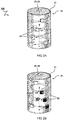
- FIGs 2A and 2B illustrate embodiments wherein the one or more acoustic transducers 21,22 are configured to cause a helical flow pattern F1,F2 in the mixing container 10.
- a helical flow pattern may comprise a general rotational flow component as well as a general longitudinal flow component transverse to the rotation.
- the mixing container 10 has a cylindrical shape to guide the helical flow.
- a set of first one or more acoustic transducers 21 is configured to cause a clockwise helical flow while a set of second one or more acoustic transducers 22 is configured to cause a counterclockwise helical flow.
- the helical flow may be guided by the cylindrical container walls 11.
- one or more transducers may be arranged to cause a fluid flow back through the middle of the container.
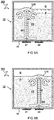
- FIGs 3A and 3B illustrate flow patterns with opposing flow directions.
- a first transducer 21a is configured to direct its acoustic waves W1a along a first acoustic axis A1a in a first direction V1a
- a second transducer 21b arranged on a second wall lib of the container is configured to (simultaneously) direct its acoustic waves W1b along a second acoustic axis A1b in a second direction V1b.
- the first direction V1a is opposite to the second direction V1b.
- the first acoustic axis A1a is offset with respect to the second acoustic axis A1b.
- a configuration of opposing non-paraxial or shearing flows may provide improved mixing, e.g. by vortex creation as illustrated. For example, this may improve mixing.
- paraxial opposing flow patterns may be envisaged which may cause a generally turbulent mixing between the transducers.
- the first transducer 21a is arranged on a first wall 11a of the mixing container 10 and the second transducer 21b is arrange on an opposing, second wall of the mixing container 10.
- one or more of the transducers 21,22 are configured to measure a respective flow pattern F1,F2.
- some of the transducers may be used to measure a flow velocity and/or flow direction.
- acoustic waves W1a may be generated by a first transducer 21a and measured by a second transducer 22b arranged in a path of the acoustic waves W1a, e.g. intersecting with the acoustic axis.
- one or more transducers are configured to measure a flow velocity by Doppler shift.
- continuous waves sent by a first transducer may be received by a second transducer, wherein the measured frequency by the second transducer is Doppler shifted with respect to the actuation of the first transducer depending on a direction and/or velocity of the flow there between.
- one or more transducers are configured to measure a flow velocity by a time of arrival measurement.
- a pulsed wave is sent by a first transducer may received by a second transducer, wherein the measured time between sending and receiving may depend on a direction and/or velocity of the flow there between (arriving faster with the flow than against the flow).
- the actuation of one or more of the transducers is controlled based on a flow measurement. For example, at least some to the actuators which are not used to generate the flow may be used to measure the flow.
- a controller [not shown here] is configured to control the one or more acoustic transducers 21,22 to automatically switch between generation of different acoustic waves W1,W2 based on the measurement. For example, the flow may be switched when it is determined that a laminar flow has developed. Typically, in a laminar flow, the flow direction and/or velocity may be substantially non-changing.
- the controller is configured to control the one or more acoustic transducers 21,22 to automatically adapt one or more of a frequency or intensity based on the measurement to keep a liquid velocity below a predetermined threshold. For example, this may prevent damage to some liquids caused by excessive shearing.
- FIGs 4A and 4B illustrate a toroidal or donut shaped mixing container 10.
- a set of transducers 21a,21b is configured to cause opposing flows in the container, e.g. similar as explained with reference to the previous figures.
- it can also be envisaged to cause a helical flow in a toroidal container.
- this allow a continuous helix around a channel formed by the container.
- FIGs 5A and 5B illustrate acoustic waves directed at an angle with respect to an opposing wall.
- an acoustic transducer 21 is arranged on a first wall 11a of the mixing container 10 and configured to direct its acoustic waves W1 along an acoustic axis A1 (central or main direction) in a direction V1 impacting an opposing (inner) second wall lib of the mixing container 10 at an impact angle ⁇ between the acoustic axis A1 and a normal An of the opposing second wall lib, wherein the impact angle ⁇ is more than twenty degrees (plane angle), preferably more than thirty or even more than forty degrees, e.g.
- directing the flow direction V1 at an angle with respect to an opposing wall may cause the flow to bounce off the wall and/or be guided along the wall.
- a circular flow may develop which mixes the fluid.
- a second transducer 22 configured to cause an opposite flow pattern (not shown).
- the mixing container 10 may be circular, or in this case cylindrical.
- the transducers may be placed off center (with respect to the centerlines of the ellipse) to impact an opposing wall at an angle.
- the circular inner wall may allow a circular flow to develop more easily.
- the mixing container 10 may have a polygonal shape, e.g. square, pentagonal, hexagonal, et cetera.
- an acoustically induced stream may be directed by one or more acoustic transducers 21,22 to impact an opposing wall at an angle to cause flow patterns along the wall.
- vortices may develop particularly at corners of the polygonal shape.
- FIGs 6A and 6B illustrate acoustic transducers 21,22 configured to direct their respective acoustic waves W1,W2 at a liquid/gas interface (L/G).
- the waves impact the interface from a direction of the liquid, e.g. from below.
- the waves traversing an interface having different acoustic impedance may cause additional flow to develop by radiation force.
- the acoustic radiation force can be understood as a nonlinear phenomenon of ultrasound propagation.
- the acoustic radiation force enacts on objects or boundaries which have an acoustical impedance difference compared to the original medium in which the acoustic waves propagated. If the radiation force enacts on a free boundary, i.e. a liquid-air interface, in combination with a liquid jet (due to acoustic streaming) impinging on said free boundary, the liquid interface can start to vibrate, which can leads to an induced liquid flow.
- a radiation force enacted on a liquid-solid boundary typically will not lead to extra liquid flow.
- the respective acoustic axis is directed at an angle, e.g. of more than thirty degrees, with respect to the normal of the interface to cause a flow along the interface surface, similar as explained in the previous figure.
- a wedge element may be arranged between the one or more acoustic transducers 21,22 and the container wall 11 to direct the waves; or the bottom walls may be sloped.
- FIG 7A illustrates a pressure distribution intensity "I" corresponding to one transducer 21.
- the acoustic waves “W” may be predominantly directed along one acoustic axis "A” to induce a corresponding flow direction "V".
- the acoustic wave field is more directional when the wavelength of the acoustic waves is small compared to one or more dimensions of the transducer on the wall.
- guided waves may be produced in the container wall.
- a frequency of the transducer may be switched between a first mode wherein the wavelength of the acoustic waves (e.g. in the container wall and/or fluid) is larger than an extent, e.g. diameter along the wall, of the transducer; and a second mode wherein the wavelength is smaller than the extent of the transducer. Accordingly, this may induce distinct wave patterns/directions.
- a frequency sweep is applied, e.g. low frequency produces different acoustic field for unfocused transducer than high frequency. There could also be combination of low and high frequency components.
- FIG 7B illustrates interference between acoustic waves of different, e.g. adjacent, transducers 21,22.
- the interference of different waves may lead to constructive and/or destructive interference.
- a distance between adjacent transducers 21,22 may be less than a wavelength ⁇ of the acoustic waves (e.g. in the fluid).
- constructive interference between acoustic waves of different transducers 21,22 may cause one or more secondary beams (grating lobes) along secondary axes A' where the pressure variation or acoustic streaming is relatively high.
- the direction of the secondary axes is dependent on the wavelength, e.g. constructive interference takes place at locations in the fluid where the distance relative to the different transducers is an integer number times the wavelength. This may be similar to an (optical) grating. It will be appreciated that the direction of the secondary axes can be controlled e.g. by controlling the frequency of the transducers. In some embodiments, a frequency of the transducers may be switched between a first mode wherein the wavelength of the acoustic waves (e.g. in the container wall and/or fluid) is larger than a (center) distance D between the transducers, e.g. along the wall; and a second mode wherein the wavelength is smaller than the distance.
- a first mode wherein the wavelength of the acoustic waves (e.g. in the container wall and/or fluid) is larger than a (center) distance D between the transducers, e.g. along the wall
- a second mode wherein the wavelength is smaller than the distance.
- an amplitude modulation of a wave field may be produced by a single transducer, or multiple transducers.
- lengths of sine wave bursts over time produced by one or more transducers can be varied.
- a shape or size of different transducers may be different between different modes.
- a first transducer actuated in a first mode has a first diameter
- a second transducer actuated in a second mode has a second diameter which may be smaller or larger than the first diameter.
- the transducers comprise an annular array, e.g. comprising (concentric rings) with different sizes or diameters.
- the transducers of different sizes may be actuated at the same or different frequencies. For example, switching between transducers may cause a change in sound field shape, e.g. because the source aperture changes. Also, the efficiency with which acoustic streaming is induced may changes (e.g. by square of the diameter dependency, as will be discussed in the formula below). When the frequencies are different this may provide an even further effect (frequency dependency also discussed below). The combination of high and low frequency components could also be used to optimize the induced fluid velocity field. Of course the different options can be combined.
- acoustic streaming may occur in all acoustic radiation fields, depending on the shape of the field and the properties of the medium (liquid/gas).
- acoustic streaming may generally be related to sound attenuation in the fluid.
- the inventors find that an induced liquid velocity by acoustic streaming can be approximated by the following proportionality relation: V ⁇ p 2 ⁇ a 2 ⁇ d c ⁇ f n c 0 ⁇ ⁇ 0 where "V” is the induced (peak) liquid velocity; "p” is the acoustic pressure in the fluid (e.g.
- p 2 may be proportional to the sound intensity I 0 at the transducer surface);
- a is the radius (or diameter) of the transducer;
- c 0 is an the acoustic wave velocity in the fluid;
- ⁇ 0 is the viscosity of the fluid;
- d c is a duty cycle of the transducer;
- f' is the frequency of the acoustic waves;
- n is a number between one and two.
- an acoustic pressure or sound intensity at the transducer surface may be controlled to provide a desired liquid velocity.
- it may be desired to prevent damage to the liquid, e.g. milk, by keeping a relatively low peak pressure in the liquid, e.g. less than one mega Pascal, preferably less than five hundred kilo Pascal, more preferably less than three hundred kilo Pascal, e.g. between one kilo Pascal and two hundred kilo Pascal. This may also depend, e.g., on the frequency.
- a frequency of the transducers is controlled to provide a desired liquid velocity.
- a frequency for mixing liquids is selected in a ranged between 0.1 - 100 MHz, preferably between 0.5 - 5 MHz, more preferably between 0.8 - 3 MHz.
- the transducers are configured to operate in a resonant mode to increase power efficiency.
- one or more, preferably all the acoustic transducers may be relatively large, e.g. more than one centimeter in diameter, more than two centimeters, more than five centimeters, or even more than ten centimeters (along the container wall). As indicated in the above relation, increasing a size of the transducer may be more efficient in achieving a desired liquid velocity.
- a relatively low peak liquid velocity e.g. less than one meter per second, less than half a meter per second, less than 0.3 m/s, or even less.
- a relatively low peak liquid velocity e.g. between 0.01 - 0.3 m/s, preferably less than 0.2 m/s, to prevent damage by shearing.
- each transducer may be powered at less than hundred Watts, less than fifty Watts, less than twenty Watts, or even less than ten Watts, e.g. between one and five Watts each. For example, mixing in a 4000 liter tank of milk may use forty transducers with total power of about 100 W.
- the mixing container has a relatively large volume.
- the container is configured to hold a volume of fluid of more than one liter, more than ten liters, more than hundred liters, or even more than a thousand liters (one cubic meter), e.g. between four thousand liter and ten thousand liters, or more.
- the present system may be applied in a container used for storage and/or or transporting of milk, e.g. in a container on the back of a truck.
- an arrangement of many acoustic transducers may be used. For example, more than ten acoustic transducers may be used, more than fifty, or even more than hundred.
- the configuration is adapted to dissipated less ten Watt per liter, less than one Watt per liter, less then half a Watt per liter, or even less than one tenth of a Watt per liter (0.1 W/l).
- measures may be taken to prevent heating of the fluid by acoustic mixing.
- the apparatus 100 comprises an active cooler to at least partially, or even fully, counteract heating of the fluid caused by the acoustic transducers.
- the active cooler has a cooling capacity which is at least equal to the heat dissipation of the acoustic waves in the fluid.
- the active cooler may be controlled based on a temperature measurement of the fluid.
- the cooling may be switched based actuation of the acoustic transducers.
- one or more acoustic transducers are configured to specifically cause a fluid flow along an actively cooled surface.
- the present teachings of contactless mixing are particularly suitable for applications where it is important to prevent contamination while mixing fluids (or keeping them mixed), such as in the food industry, medicine, or general chemical industry.
- milk has a typical viscosity of three Centipoise (at room temperature.
- the fluid being mixed is milk wherein the configuration is controlled to keep a peak liquid velocity below thirty centimeters per second, and a peak acoustic pressure kept below one mega Pascal.
Priority Applications (6)
| Application Number | Priority Date | Filing Date | Title |
|---|---|---|---|
| EP19162758.7A EP3708247A1 (fr) | 2019-03-14 | 2019-03-14 | Mélange non invasif de liquides |
| US17/437,745 US20220143563A1 (en) | 2019-03-14 | 2020-03-12 | Non-invasive mixing of liquids |
| EP20713997.3A EP3938090A1 (fr) | 2019-03-14 | 2020-03-12 | Mélange non invasif de liquides |
| JP2021555260A JP2022525598A (ja) | 2019-03-14 | 2020-03-12 | 液体の非侵襲混合 |
| PCT/NL2020/050164 WO2020185085A1 (fr) | 2019-03-14 | 2020-03-12 | Mélange non invasif de liquides |
| CN202080029614.6A CN113710355A (zh) | 2019-03-14 | 2020-03-12 | 液体的非入侵性混合 |
Applications Claiming Priority (1)
| Application Number | Priority Date | Filing Date | Title |
|---|---|---|---|
| EP19162758.7A EP3708247A1 (fr) | 2019-03-14 | 2019-03-14 | Mélange non invasif de liquides |
Publications (1)
| Publication Number | Publication Date |
|---|---|
| EP3708247A1 true EP3708247A1 (fr) | 2020-09-16 |
Family
ID=65812164
Family Applications (2)
| Application Number | Title | Priority Date | Filing Date |
|---|---|---|---|
| EP19162758.7A Withdrawn EP3708247A1 (fr) | 2019-03-14 | 2019-03-14 | Mélange non invasif de liquides |
| EP20713997.3A Withdrawn EP3938090A1 (fr) | 2019-03-14 | 2020-03-12 | Mélange non invasif de liquides |
Family Applications After (1)
| Application Number | Title | Priority Date | Filing Date |
|---|---|---|---|
| EP20713997.3A Withdrawn EP3938090A1 (fr) | 2019-03-14 | 2020-03-12 | Mélange non invasif de liquides |
Country Status (5)
| Country | Link |
|---|---|
| US (1) | US20220143563A1 (fr) |
| EP (2) | EP3708247A1 (fr) |
| JP (1) | JP2022525598A (fr) |
| CN (1) | CN113710355A (fr) |
| WO (1) | WO2020185085A1 (fr) |
Citations (4)
| Publication number | Priority date | Publication date | Assignee | Title |
|---|---|---|---|---|
| US6210128B1 (en) * | 1999-04-16 | 2001-04-03 | The United States Of America As Represented By The Secretary Of The Navy | Fluidic drive for miniature acoustic fluidic pumps and mixers |
| US20090074621A1 (en) * | 2006-03-16 | 2009-03-19 | Olympus Corporation | Stirrer and analyzer |
| EP2333562A1 (fr) * | 2008-10-03 | 2011-06-15 | Beckman Coulter, Inc. | Agitateur et analyseur |
| CN105854715B (zh) * | 2016-04-21 | 2019-03-05 | 北京百思声创科技有限公司 | 超声搅拌容器 |
Family Cites Families (3)
| Publication number | Priority date | Publication date | Assignee | Title |
|---|---|---|---|---|
| WO2007015438A1 (fr) * | 2005-08-03 | 2007-02-08 | Olympus Corporation | Dispositif de melange et dispositif d’analyse equipe de ce dispositif de melange |
| JPWO2007043147A1 (ja) * | 2005-10-05 | 2009-04-16 | オリンパス株式会社 | 攪拌容器、攪拌方法、攪拌装置及び攪拌装置を備えた分析装置 |
| US20080116074A1 (en) * | 2006-11-21 | 2008-05-22 | Eilaz Babaev | Ultrasonic device for treating a continuous flow of fluid |
-
2019
- 2019-03-14 EP EP19162758.7A patent/EP3708247A1/fr not_active Withdrawn
-
2020
- 2020-03-12 US US17/437,745 patent/US20220143563A1/en active Pending
- 2020-03-12 EP EP20713997.3A patent/EP3938090A1/fr not_active Withdrawn
- 2020-03-12 WO PCT/NL2020/050164 patent/WO2020185085A1/fr unknown
- 2020-03-12 CN CN202080029614.6A patent/CN113710355A/zh active Pending
- 2020-03-12 JP JP2021555260A patent/JP2022525598A/ja active Pending
Patent Citations (4)
| Publication number | Priority date | Publication date | Assignee | Title |
|---|---|---|---|---|
| US6210128B1 (en) * | 1999-04-16 | 2001-04-03 | The United States Of America As Represented By The Secretary Of The Navy | Fluidic drive for miniature acoustic fluidic pumps and mixers |
| US20090074621A1 (en) * | 2006-03-16 | 2009-03-19 | Olympus Corporation | Stirrer and analyzer |
| EP2333562A1 (fr) * | 2008-10-03 | 2011-06-15 | Beckman Coulter, Inc. | Agitateur et analyseur |
| CN105854715B (zh) * | 2016-04-21 | 2019-03-05 | 北京百思声创科技有限公司 | 超声搅拌容器 |
Also Published As
| Publication number | Publication date |
|---|---|
| EP3938090A1 (fr) | 2022-01-19 |
| WO2020185085A1 (fr) | 2020-09-17 |
| US20220143563A1 (en) | 2022-05-12 |
| CN113710355A (zh) | 2021-11-26 |
| JP2022525598A (ja) | 2022-05-18 |
Similar Documents
| Publication | Publication Date | Title |
|---|---|---|
| US9011698B2 (en) | Method and devices for sonicating liquids with low-frequency high energy ultrasound | |
| US6244738B1 (en) | Stirrer having ultrasonic vibrators for mixing a sample solution | |
| EP2591864B1 (fr) | Sonotrode et dispositif pour réduire et éliminer le moussage de produits liquides | |
| US7253551B2 (en) | Apparatus to produce acoustic cavitation in a liquid insonification medium | |
| US6039309A (en) | Method and apparatus for producing gas bubbles in a liquid medium | |
| JP2001000933A (ja) | 超音波シャワー洗浄装置 | |
| US20220143563A1 (en) | Non-invasive mixing of liquids | |
| JP2014198327A (ja) | 微細気泡製造方法及び製造装置 | |
| JP2009208217A (ja) | ショットピーニング装置及びショットピーニング用振動子 | |
| KR20160136493A (ko) | 횡파 발생 방지가 가능한 압전소자를 가진 초음파 진동자 및 이를 포함하는 초음파 세정 장치 | |
| US11148178B2 (en) | Ultrasonic cleaner and automatic analyzer using the same | |
| CN100537019C (zh) | 超声液体处理换能方法和装置 | |
| US20210039128A1 (en) | Acoustic droplet ejection | |
| WO2000054095A2 (fr) | Procede et appareil permettant une operation d'homogeneisation integree optimale | |
| JP6772362B2 (ja) | 容器を流体で充填するための流体充填ノズル、装置、及び方法 | |
| JP5081487B2 (ja) | 超音波分散装置 | |
| US8763927B2 (en) | Ultrasonic transducer systems | |
| US10562068B2 (en) | Ultrasonic device having large radiating area | |
| JPH01203029A (ja) | 混濁器 | |
| JP2005186030A (ja) | 超音波放射体、超音波放射ユニット、超音波放射装置、及びこれを用いた超音波処理装置 | |
| US11598663B2 (en) | Transducer for non-invasive measurement | |
| RU2540608C1 (ru) | Способ ультразвуковой кавитационной обработки жидких сред | |
| ES2893279B2 (es) | Dispositivo sonorreactor intensificado a multifrecuencia | |
| US20230111845A1 (en) | Fluid device | |
| JP4459246B2 (ja) | マイクロミキサー |
Legal Events
| Date | Code | Title | Description |
|---|---|---|---|
| PUAI | Public reference made under article 153(3) epc to a published international application that has entered the european phase |
Free format text: ORIGINAL CODE: 0009012 |
|
| STAA | Information on the status of an ep patent application or granted ep patent |
Free format text: STATUS: THE APPLICATION HAS BEEN PUBLISHED |
|
| AK | Designated contracting states |
Kind code of ref document: A1 Designated state(s): AL AT BE BG CH CY CZ DE DK EE ES FI FR GB GR HR HU IE IS IT LI LT LU LV MC MK MT NL NO PL PT RO RS SE SI SK SM TR |
|
| AX | Request for extension of the european patent |
Extension state: BA ME |
|
| STAA | Information on the status of an ep patent application or granted ep patent |
Free format text: STATUS: THE APPLICATION IS DEEMED TO BE WITHDRAWN |
|
| 18D | Application deemed to be withdrawn |
Effective date: 20210317 |