EP3708073A1 - Patientenüberwachungsvorrichtung - Google Patents
Patientenüberwachungsvorrichtung Download PDFInfo
- Publication number
- EP3708073A1 EP3708073A1 EP20162781.7A EP20162781A EP3708073A1 EP 3708073 A1 EP3708073 A1 EP 3708073A1 EP 20162781 A EP20162781 A EP 20162781A EP 3708073 A1 EP3708073 A1 EP 3708073A1
- Authority
- EP
- European Patent Office
- Prior art keywords
- electrodes
- electrode
- components
- suite
- module
- Prior art date
- Legal status (The legal status is an assumption and is not a legal conclusion. Google has not performed a legal analysis and makes no representation as to the accuracy of the status listed.)
- Withdrawn
Links
Images








Classifications
-
- A—HUMAN NECESSITIES
- A61—MEDICAL OR VETERINARY SCIENCE; HYGIENE
- A61B—DIAGNOSIS; SURGERY; IDENTIFICATION
- A61B5/00—Measuring for diagnostic purposes; Identification of persons
- A61B5/24—Detecting, measuring or recording bioelectric or biomagnetic signals of the body or parts thereof
- A61B5/25—Bioelectric electrodes therefor
- A61B5/279—Bioelectric electrodes therefor specially adapted for particular uses
- A61B5/28—Bioelectric electrodes therefor specially adapted for particular uses for electrocardiography [ECG]
- A61B5/282—Holders for multiple electrodes
-
- A—HUMAN NECESSITIES
- A61—MEDICAL OR VETERINARY SCIENCE; HYGIENE
- A61B—DIAGNOSIS; SURGERY; IDENTIFICATION
- A61B5/00—Measuring for diagnostic purposes; Identification of persons
- A61B5/24—Detecting, measuring or recording bioelectric or biomagnetic signals of the body or parts thereof
- A61B5/25—Bioelectric electrodes therefor
- A61B5/271—Arrangements of electrodes with cords, cables or leads, e.g. single leads or patient cord assemblies
- A61B5/273—Connection of cords, cables or leads to electrodes
- A61B5/274—Connection of cords, cables or leads to electrodes using snap or button fasteners
-
- A—HUMAN NECESSITIES
- A61—MEDICAL OR VETERINARY SCIENCE; HYGIENE
- A61B—DIAGNOSIS; SURGERY; IDENTIFICATION
- A61B5/00—Measuring for diagnostic purposes; Identification of persons
- A61B5/24—Detecting, measuring or recording bioelectric or biomagnetic signals of the body or parts thereof
- A61B5/316—Modalities, i.e. specific diagnostic methods
- A61B5/318—Heart-related electrical modalities, e.g. electrocardiography [ECG]
- A61B5/332—Portable devices specially adapted therefor
-
- A—HUMAN NECESSITIES
- A61—MEDICAL OR VETERINARY SCIENCE; HYGIENE
- A61B—DIAGNOSIS; SURGERY; IDENTIFICATION
- A61B5/00—Measuring for diagnostic purposes; Identification of persons
- A61B5/68—Arrangements of detecting, measuring or recording means, e.g. sensors, in relation to patient
- A61B5/6801—Arrangements of detecting, measuring or recording means, e.g. sensors, in relation to patient specially adapted to be attached to or worn on the body surface
- A61B5/683—Means for maintaining contact with the body
- A61B5/6832—Means for maintaining contact with the body using adhesives
- A61B5/6833—Adhesive patches
-
- A—HUMAN NECESSITIES
- A61—MEDICAL OR VETERINARY SCIENCE; HYGIENE
- A61B—DIAGNOSIS; SURGERY; IDENTIFICATION
- A61B5/00—Measuring for diagnostic purposes; Identification of persons
- A61B5/68—Arrangements of detecting, measuring or recording means, e.g. sensors, in relation to patient
- A61B5/6846—Arrangements of detecting, measuring or recording means, e.g. sensors, in relation to patient specially adapted to be brought in contact with an internal body part, i.e. invasive
- A61B5/6879—Means for maintaining contact with the body
- A61B5/688—Means for maintaining contact with the body using adhesives
-
- A—HUMAN NECESSITIES
- A61—MEDICAL OR VETERINARY SCIENCE; HYGIENE
- A61B—DIAGNOSIS; SURGERY; IDENTIFICATION
- A61B2560/00—Constructional details of operational features of apparatus; Accessories for medical measuring apparatus
- A61B2560/02—Operational features
- A61B2560/0204—Operational features of power management
- A61B2560/0214—Operational features of power management of power generation or supply
-
- A—HUMAN NECESSITIES
- A61—MEDICAL OR VETERINARY SCIENCE; HYGIENE
- A61B—DIAGNOSIS; SURGERY; IDENTIFICATION
- A61B2560/00—Constructional details of operational features of apparatus; Accessories for medical measuring apparatus
- A61B2560/02—Operational features
- A61B2560/0242—Operational features adapted to measure environmental factors, e.g. temperature, pollution
- A61B2560/0247—Operational features adapted to measure environmental factors, e.g. temperature, pollution for compensation or correction of the measured physiological value
- A61B2560/0252—Operational features adapted to measure environmental factors, e.g. temperature, pollution for compensation or correction of the measured physiological value using ambient temperature
-
- A—HUMAN NECESSITIES
- A61—MEDICAL OR VETERINARY SCIENCE; HYGIENE
- A61B—DIAGNOSIS; SURGERY; IDENTIFICATION
- A61B2562/00—Details of sensors; Constructional details of sensor housings or probes; Accessories for sensors
- A61B2562/02—Details of sensors specially adapted for in-vivo measurements
- A61B2562/0219—Inertial sensors, e.g. accelerometers, gyroscopes, tilt switches
-
- A—HUMAN NECESSITIES
- A61—MEDICAL OR VETERINARY SCIENCE; HYGIENE
- A61B—DIAGNOSIS; SURGERY; IDENTIFICATION
- A61B2562/00—Details of sensors; Constructional details of sensor housings or probes; Accessories for sensors
- A61B2562/02—Details of sensors specially adapted for in-vivo measurements
- A61B2562/0271—Thermal or temperature sensors
-
- A—HUMAN NECESSITIES
- A61—MEDICAL OR VETERINARY SCIENCE; HYGIENE
- A61B—DIAGNOSIS; SURGERY; IDENTIFICATION
- A61B5/00—Measuring for diagnostic purposes; Identification of persons
- A61B5/01—Measuring temperature of body parts ; Diagnostic temperature sensing, e.g. for malignant or inflamed tissue
Definitions
- the subject matter described herein relates to a wearable suite of components for monitoring a subject, such as a medical patient, and to a method of preparing the patient for monitoring by the suite of components.
- Parameters of interest include vital signs such as respiration rate, and cardiac signals including signals necessary to establish the patient's heart rate.
- the parameters of interest may also include parameters not traditionally thought of as vital signs such as the patient's position (particularly his position in or relative to a bed) and patient movements including velocity and acceleration.
- references to vital signs or other patient related parameters may refer to the vital sign itself or may refer to the signals detected by sensors, typically electrical signals, processing of which leads to an estimate of the parameter of interest.
- respiration rate may mean the number of breaths per unit time or may mean the sensed signals which can be processed to estimate the number of breaths per unit time.
- Parameter monitoring as described above is often carried out in health care settings such as hospitals. Monitoring may also be carried out while the patient goes about his day to day activities. Wearable monitors, which contain the sensors and other components required for the monitoring task, are attractive for such purposes.
- a wearable monitior is one that is maintained in a fixed position on the patient, for example by being adhered to his skin.
- “Position” refers to the location of the sensor relative to anatomical features of the patient and may also include the locations or orientations of the sensors relative to each other.
- “Fixed” means that the position of each sensor remains sufficiently unchanged that its readings remain valid and useful during the time interval that the monitor is in use.
- a compact, wearable monitor may satisfy monitoring requirements that would otherwise call for the use of multiple pieces of expensive, bulky equipment.
- wearable monitor offers the patient considerable freedom to go about his normal daily activities.
- Wearable monitors present a number of design challenges.
- certain of the monitor's sensors must be accurately positioned on the patient in order to achieve the best possible readings. If the patient is to be monitored for a period of, say, several days, it is desirable to leave those sensors in place for the entire duration of the monitoring period. This is because if the sensors are removed and subsequently reapplied to the patient, a caregiver will have to devote time and effort to re-establish accurate positions for the sensors. Even if the caregiver is able to do so, the subsequent location may differ somewhat from the previous location, compromising the repeatability of measuring the signals of interest.
- the means used to hold the sensor onto the patient should be breathable in order to allow for air circulation to the patient's skin.
- the monitor should be comfortable to wear and durable.
- Another design challenge is that some of the monitor's sensors, and/or the electrical components associated with them, might not be tolerant of degrading influences such as radiation exposure during a radiological procedure. Therefore, notwithstanding the desirability of leaving sensors in place for the entire duration of the monitoring period, there may be a need to remove certain sensors from the patient while the degrading influence is present and reapply them to the patient after the degrading influence is no longer present. As noted above it is desirable to re-apply the removed sensors in essentially the same position they occupied relative to the patient's anatomical features prior to removal.
- the suite of components may also be considered to be a kit of components.
- the suite of components may also be considered to be a system of components, at least when the components are assembled to each other in order to monitor the patient.
- the component suite includes one or more ECG electrodes, a securement component adapted to hold the one or more electrodes to the subject's body, and a host removably connected to or adapted to be removably connected to the one or more electrodes.
- the host includes a sensor, a processor and an energy source.
- This specification also describes a method of preparing a subject for monitoring with a suite of components which includes 1) one or more electrodes each having a contact portion with an adhesive surface and a snap assembly projecting away from an opposite or top surface of the contact portion, 2) a securement component having an adhesive side and one or more holes with each hole corresponding to a pre-established electrode pattern, and 3) a host adapted to receive and remain removably attached to the electrodes.
- the method itself includes the steps of A) installing the electrodes in the module thereby forming an electrode/module subassembly, B) placing the subassembly at a monitoring site on the subject whereby the adhesiveness of the adhesive surface of the electrodes causes the electrodes to adhere to the subject, C) disconnecting the module from the adhered electrodes, D) adhering the securement component to the subject so that each snap assembly projects through one of the holes in the securement component, and E) reconnecting the module to the adhered electrodes.
- the invention at least in the preferred embodiments provides a means to effect the attachment of a wearable monitor to a patient which has the attributes of breathability, durability, and comfort.
- the attachment means is resistant to influences that tend to separate the attachment means from the patient and which is resistant to degrading influences.
- the monitor includes sensors that are not resistant to degrading influences, the monitor has an architecture which enables those sensors to be temporarily and conveniently removed, and to be conveniently put back in place after the degrading influence is no longer present.
- a suite of components for monitoring a person includes one or more electrocardiogram (ECG) electrodes 50.
- ECG electrocardiogram
- the illustration shows four electrodes mounted on an electrode release liner 52. Arrangements other than that of FIG. 1 are described elsewhere in this specification.
- Each electrode 50 includes a patch of comfort gel 54 and a ring of hydrocolloid adhesive 56 whose outer and inner diameters both exceed the diameter of gel patch 54.
- Adhesive 56 adheres the electrode to the patient's skin however, as described below, is not the exclusive means for maintaining the electrode at a fixed position on the patient.
- the comfort gel makes the electrode more comfortable to the patient.
- Each electrode also includes a lower pressure sensitive adhesive layer 62, a polyethelene layer 64, an upper foam pressure sensitive adhesive layer 66, and a foam layer 68.
- components 54, 56, 62, 64, 66, 68, are referred to as the contact portion 72 of the electrode.
- Each electrode also includes a snap assembly 74 comprising an electrode magnetic snap 76 and an electrode eyelet 78. When the electrode is in its assembled state, eyelet 78 nests inside magnetic snap 76, and the snap assembly projects above electrode contact portion 72.
- magnetic snap 76 of the illustrated embodiment is ferrous, but is not magnetic.
- the snap assembly and a host component of the component suite are removably connected to each other. However despite the nomenclature "snap", the connection is a magnetic connection, not a mechanical snap connection.
- FIGS. 5-7 show a securement component 90 of the suite of components.
- the securement component is adapted to hold the one or more electrodes 50 to the patient's body.
- the securement component supplements electrode adhesive 56.
- the securement component is in the form of a thin pad or patch having a racetrack shaped planform (parallel straight edges joined by first and second arcs) a bottom or patient facing side 92 and a top or non-patient side 94.
- Two holes 96 penetrate through the securement component.
- Patient side 92 is covered with a one piece release liner 100 having a perforation 102 that extends from the border of the securement component to one of the holes. As illustrated the release liner has been partially peeled away to reveal an adhesive 104 on the bottom side of the securement component.
- top side 94 is covered with a two piece release liner 110 having a perforation 112 that extends across the width of the securement component. In the elevation view of FIG. 7 the perforations are indicated by vertical marks 102, 112.
- the adhesive 104 employed on the bottom of the securement component is one that adheres strongly enough to the patient's skin to resist detachment for a specified period of time, for example approximately seven days, and weakly enough to be intentionally removed from the patient's skin without damaging the patient's skin.
- One benchmark for skin damage is breaking the skin.
- TegadermTM transparent film dressing a 3MTM product.
- Tegaderm is said to provide a waterproof, sterile barrier to external contaminants, has an adhesive which is gentle to the skin, and flexes with the skin to enhance patient comfort.
- FIGS. 8-15 show a host component 130 of the suite of components.
- the host is adapted to be removably connected to the one or more electrodes 50 such that the hose receives the electrodes, hence the nomenclature "host".
- the host includes at least a sensor (other than the ECG electrodes) a processor, and an energy source. As shipped by the manufacturer or distributor, and as initially encountered by an end user, the host is separate from the ECG electrodes.
- the electrodes are removably pre-installed in the host. As will be appreciated from a complete reading of this specification, the host will be disengaged from the pre-installed electrodes and will later be re-engaged with the electrodes when the component suite is applied to a patient.
- end user means as first seen by the end user who unpackages the components from their shipping container(s).
- the end user may be a caregiver or, in a "direct to consumer” environment, may be the patient, who serves as his own caregiver.
- the phrase "end user” may also apply to a person who unpackages the components on behalf of the patient, caregiver, or patient/caregiver, even though that person is not, strictly speaking, a user of the monitor.
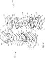
- the illustrated host 130 includes a first module 132 which is referred to herein as a power module 132.
- the power module includes a first housing 136 comprised of a first housing base 138 and a first housing cover 140.
- the first base and the first cover define an interior 142 of the first housing.
- Housing base 138 has two coupler openings, 146.
- the housing cover includes a perimeter flange 152 and an archway 154.
- a housing adhesive, not shown, on at least the top of the perimeter flange is provided to connect the cover to the base.
- the power module also includes a chassis adhesive 156 and a chassis 158.
- the chassis includes internally threaded posts 166 at each corner thereof, a central opening 168, and an archway seat 170 shaped similarly to archway 154 except for a longitudinally projecting tube segment 172.
- the bottom of the chassis also includes recesses 174.
- the power module also includes a Qi charging receiver 180, a Qi receiver adhesive 182 which holds charging receiver 180 to chassis 158, a battery 184, and a foam battery spacer 186 between the battery and the Qi receiver.
- the battery is the energy source for the host.
- Qi charging works by transferring energy from a nearby charger, which is external to the host, to the receiver by way of electromagnetic induction.
- the charger uses an induction coil to create an alternating electromagnetic field, which the receiver converts back into electricity to be fed into the battery.
- Wireless charging arrangements other than Qi charging may be used. Wired charging arrangements may also be used.
- the power module also includes a battery cover 190. Screws 192 threaded into posts 166 secure the battery cover to the chassis so that battery 184, spacer 186, Qi receiver 180, and Qi receiver adhesive 182 are contained with a space defined by the battery cover and chassis.
- cover 140 and base 138 are sealed to each other at cover flange 152, the battery cover 190, battery 184, spacer 186, Qi receiver 180, Qi receiver adhesive 182, chassis 158 and chassis adhesive 156 are all contained in the interior space defined by the base and cover.
- Magnetic electrode couplers 210S - , 210D - reside in chassis recesses 174.
- Magnetic as used in the phrase “magnetic electrode coupler” indicates that the coupler is magnetic. This is in contrast to magnetic snaps 76 of electrodes 50 which, as previously noted, are ferrous but not magnetic.
- the locations of the couplers are referred to as connection sites and are identified with reference numeral 212.
- magnetic attraction between the magnetic couplers 210S - , 210D - and snaps 76 of electrode snap assembly 74 cause power module 132 to be removably engaged with the ECG electrodes.
- the couplers also serve as impedance plethysmography (IPG) negative drive and sense electrodes, hence the D - and S - suffixes.
- IPG impedance plethysmography
- the unsuffixed reference numeral 210 may be used herein when the text is referring to the coupling function of the couplers but not to their plethysmography function.
- the illustrated host also includes a second module 232 which is referred to herein as a processor module 232.
- a processor module 232 includes a second module 232 which is referred to herein as a processor module 232.
- the processor module chassis adhesive 256, chassis 258, magnetic couplers 310S + , 310D + (analogous to couplers 210S - , 210D - of power module 132), and adhesive band 294 are the same as their counterpart elements of the power module.
- the processor module housing cover 240 is the same as the power module housing cover 140 except that the processor module has a heart shaped emblem 320, and the power module is either plain as in FIG. 13 or includes instructions and/or other information and markings, depicted generally as feature 220, as seen best in FIGS. 8 and 13 .
- the processor module housing base 238 is the same as the power module housing base 138 except that housing base 238 includes a center opening 248.
- the visible difference in the covers remind the caregiver of the correct polarity of the modules, namely that the power module should be positioned to the right of the patient's medial anatomical plane and the processor module should be situated to the left of the medial plane.
- the heart shaped emblem also reveals the location of an ON/OFF switch 322, which is below the emblem as seen best in FIGS. 13 and 15 .
- cover 240 is pliable enough that a person can press down on the cover to actuate the ON/OFF switch.
- the processor module also includes a temperature sensing assembly 330 comprised of a sensor housing 332, a temperature sensor 334 and temperature sensor circuitry 336.
- the illustrated temperature sensor is an infrared sensor, i.e. it is responsve to infrared wavelengths.
- the illustrated sensor circuitry is a printed circuit assembly (PCA). As seen best in FIG. 15 , the temperature sensing assembly occupies the central opening 268 of the chassis and the center opening 248 of the housing base. An infrared transparent window 348 covers opening 248 to resist ingress of contaminants.
- the processor module also includes a foam spacer layer 340 with a center hole 342, and a main circuit board or main PCA 346. Wires, not shown, pass through center hole 342. A foam plug 344 also occupies the hole. Together, foam layer 340 and plug 344 provide thermal and electrical insulation between main PCA 346 and temperature sensor 334.
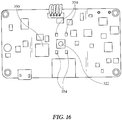
- the main PCA includes a processor 350, an ON/OFF switch 322, an accelerometer 352, ( FIG. 15 ), Qi charging circuitry (not illustrated), and the connections to the IPG drive and sense electrodes 210S - , 210D - , 310S + , 310D + .
- the PCA also includes one or more light emitting diodes (LED's) 354. Light emitted by the LED's can be seen through cover 240 of processor module 232. The LED's may be used to indicate whether the monitor is ON or OFF and may also be used to indicate information other than ON/OFF.
- the PCA also includes circuitry for generating IPG drive signals and for processing the signals from the IPG sense electrodes.
- the PCA also includes circuitry for extracting information from the ECG electrodes.
- Processor module 232 also includes a PCA cover 360 with a heart shaped opening 362. When the module is assembled as seen in FIGS. 8-11 , heart shaped opening 362 registers with heart shaped emblem 320 on housing cover 240.
- the processor module may also include a wireless radio circuitry (not illustrated) to convey parameter signals of interest to an off-board receiver.
- the processor module includes at least one sensor. These may include IPG sensors for estimating the patient's respiratory rate, temperature sensor 334 for estimating the patient's skin temperature, and an acceleration sensor 352. Readings from the accelerometer may be used to monitor for accelerations that might indicate a health related problem (e.g. tremors, shivering, coughing) or might indicate that the patient in moving in an undesirable way (e.g. attempting to make an unauthorized exit from his bed). The accelerometer readings may also be integrated or double integrated over time to establish an estimate of the speed of patient movement and the patient's present position.
- IPG sensors for estimating the patient's respiratory rate
- temperature sensor 334 for estimating the patient's skin temperature
- an acceleration sensor 352 for a sensor that might indicate a health related problem (e.g. tremors, shivering, coughing) or might indicate that the patient in moving in an undesirable way (e.g. attempting to make an unauthorized exit from his bed).
- the accelerometer readings may also be integrated or double
- Host 130 also includes a conduit 370.
- Each end of the conduit circumscribes one of the tube segments 172, 272 that extend from the chassis of the power and processor modules.
- An adhesive not shown is applied to the outside surface of the tube segments to help secure the connection.
- the tubes may also be barbed to resist separation of the conduit.
- the conduit has a length such that when the ECG electrodes are correctly positioned on the patient and engaged with modules 132, 232, the conduit will accommodate a patient size range from a 5th percentile female to a 95th percentile male.
- Wiring not shown, extends through the conduit.
- the wiring includes two wires from the battery, two wires connecting the Qi charger to the Qi charger circuitry, one wire from the IPG sense electrode and one wire from the IPG drive electrode.
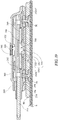
- FIG. 19 is a cross sectional side elevation view showing the relationship among the host component 130 (represented by power module 132), the securement component 90 and ECG electrode component(s) 50 when the component suite is being employed to monitor the patient.
- the ECG electrodes 50 adhere to the patient's skin S by way of the ring of hydrocolloid adhesive 56 ( FIG. 1 ).
- securement component release liners 100, 110 have been previously removed so that the adhesive 104 on the bottom side of the securement layer is exposed.
- a first portion 380 of the securement component (indicated by the dashed borders) overlies the contact portions of the electrodes.
- a second portion 382 of the securement component sticks to the patient's skin.
- the securement component supplements the electrode hydrocolloid adhesive 56.
- the adhesive 104 of the securement component helps provide a watertight seal around the perimeters of the ECG electrodes.
- the electrode snap assemblies 74 project through holes 96 in the securement component.
- Host 130 is removably connected to the ECG electrodes so that securement component 90 resides between the patient and base 238 of the module.
- the connection is effected by the attraction of the magnetic snap 76 of the electrodes to the magnetized magnetic coupler 310 of the module.
- the connection is both a mechanical connection and an electrical connection between the host and the electrodes.
- the electrical connection transports signals from the ECG electrodes.
- Power module 132 is similarly removably engaged with other ECG electrodes by the magnetic attraction between the magnetic snaps of those electrodes to power module magnetic couplers 210. If desired, the mechanical connection could be made by mechanical snaps or some other nonmagnetic arrangement.
- the securement component adheres strongly to the patient's skin and resists influences that tend to separate it from the patient's skin.
- the ECG electrodes are therefore held in place.
- the securement component adheres weakly enough to be intentionally removed from the patient's skin without damaging the skin.
- the magnetic attraction between electrode snaps 76 and housing magnetic couplers 210, 310 is strong enough to hold the module and its sensors in a fixed position relative to the ECG electrodes, and therefore in a fixed position relative to the patient's anatomical features.
- the magnetic attraction is strong enough to achieve this state of securement even if the module is bumped or otherwise exposed to actions or conditions that might dislodge it from the electrodes.
- the magnetic attraction is weak enough that if the module needs to temporarily removed, such removal can be easily accomplished without special tools and with a force well within the capabilities of a human caregiver. As already explained such temporary removal might be required to avoid subjecting the module, or the components contained within it, to a degrading influence such as radiation.
- the required separation force is also small enough that its application will break the magnetic bond at the snap/coupler interface rather than separating the securement component from the patient's skin.
- the host can be a single module or can be comprised of three or more modules, rather than the two modules described so far.
- Each module may include fewer or more than the two connection sites described above.
- the quantity of connection sites need not be the same on all the modules. If the quantity of connection sites is the same on two or more modules, is it not necessary for the spatial distribution pattern of those connection sites to be the same.
- a first of the two modules is adapted to be removably connected to M ECG electrodes.
- the first module includes exactly M electrode connection sites, one for each of the M ECG electrodes.
- the M electrode connection sites are spatially distributed in a first connection site pattern.
- Connection site pattern means the spatial relationships amongst the M connection sites.
- a second module is adapted to be removably connected to N ECG electrodes.
- the second module includes exactly N electrode connection sites, one for each of the N ECG electrodes.
- the N electrode connection sites are spatially distributed in a second connection site pattern.
- the set of M electrodes may be packaged so that they are spatially distributed in a first electrode pattern which matches the first connection site pattern.
- the electrode connection sites on the first module e.g. power module 132 are arranged in a first connection site pattern in which site 212B is spaced from site 212A by a spacing S AB,X in the X direction, and site 212C is spaced from site 212B by a spacing S BC,X in the X direction and by a spacing S BC,Y in the Y direction.
- a bridge 386 packages electrodes 212A, 212B, 212C together so that the electrodes are arranged in a first electrode pattern which matches the first connection site pattern.
- the user can insert the electrode snap assemblies into the electrode couplers at the connection sites as a unit, rather than having to deal with each electrode individually.
- the bridge When the bridge is no longer needed, or when its presence is no longer of value, it can be released from the electrodes and discarded or recycled.
- the set of N electrodes may be packaged similarly to the way just described in connection with the set of M electrodes so that they are spatially distributed in a second electrode pattern which matches the second connection site pattern.
- the above example of the M electrode arrangement suffices for the reader to understand the N electrode arrangement.
- the first and second connection site patterns may be replicas of each other or may differ from each other.
- FIG. 24 shows an alternative in which the bridge is nonrigid (in the illustrated example M (or N) equals two). Therefore the ECG electrodes, as initially encountered by an end user, may not be spatially distributed in an electrode pattern that matches the host connection site pattern (solid lines). However because the bridge can be unfolded (dashed lines) the electrodes are distributable in an electrode pattern that matches the host connection site pattern.
- FIG. 25 shows a specific example in which host 130 includes exactly two modules, first module 132 and second module 232.
- the first module includes exactly two connection sites 212A, 212B spaced apart by a first site spacing S S1 .
- the second module also includes exactly two connection sites 312A, 312B spaced apart by a second site spacing S S2 .
- the one or more electrodes comprises a first set 390 of exactly two electrodes and a second set 392 of exactly two electrodes.
- the electrodes of the first set are spaced from each other by a first electrode spacing S E1 (or are constrained to be spaceable from each other by no more than the first electrode spacing S E1 , for example by using a nonrigid bridge as explained above).
- Spacing S E1 equals spacing S S1 .
- the electrodes of the second set are spaced from each other by a second electrode spacing S E2 (or are constrained to be spaceable from each other by no more than the second electrode spacing S E2 ).
- Spacing S E2 equals spacing S S2 .
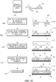
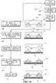
- FIG. 26 is a block diagram showing a method of preparing a patient for monitoring with a suite of components which includes 1) one or more electrodes each having a contact portion with an adhesive surface and a snap assembly projecting away from an opposite surface of the contact portion, 2) a securement component having an adhesive side and one or more holes, each of which corresponds to a pre-established electrode pattern, and 3) a host adapted to receive and be removably attached to the electrodes.
- the host is represented by a single module, for example power module 132 or processor module 134.
- FIG. 26 also includes a hardware schematic next to each block to show the hardware configuration that results from the performance of each step of the method.
- the method includes the step, at block 400, of installing the electrodes 50 in the module 132 thereby forming an electrode/module subassembly 394.
- the method also includes the step, at block 408, of placing subassembly 394 at a monitoring site on a patient.
- the adhesiveness of the adhesive surface causes the electrodes to adhere to the patient, e.g. to his skin.
- the method also includes the step, at block 410, of disconnecting the module from the adhered electrodes.
- a caregiver lifts up the module, breaking the magnetic connection between the snap assemblies of the electrodes and the magnetic coupler of the host.
- the adhesiveness of the adhesive surface causes the electrodes to remain adhered to the patient.
- the method also includes the step, at block 412, of adhering the securement component to the patient so that each snap assembly 74 projects through one of holes 96 in the securement component.
- the method also includes the step, at block 414, of reconnecting the module to the adhered electrodes.
- the caregiver places the module over the electrodes so that the magnetic connection between each electrode and its companion magnetic coupler is re-established.
- the monitor is secured to the patient, with the module removably secured to the electrodes. Securement of the electrodes to the patient is enhanced by the presence of securement layer 90. The caregiver may then press the ON/OFF switch on the module to commence patient monitoring.
- FIGS. 27-33 are views illustrating the steps of the block diagram of FIG. 26 in the context of a patient.
- FIG. 27 shows the module/electrode subassemblies placed against the patient's chest at a selected monitoring site, corresponding to block diagram block 408.
- FIG. 28 shows that after the modules have been disengaged from the electrodes, the electrodes remain adhered to the patient.
- FIG. 28 corresponds to block diagram block 410.
- the four electrodes define a single lead ECG arrangement.
- Electrode 50A, 50B, 50C, 50D mate respectively with with magnetic couplers (IDG sense and drive electrodes) 210S-, 210D-, 310D+, 310S+.
- the electrodes are placed symmetrically relative to the patient's sternum.
- the uppermost electrode of the left electrode pair is approximately laterally aligned with the middle of the patient's left clavicle.
- the uppermost electrode of the right electrode pair is approximately laterally aligned with the middle of the patient's right clavicle.
- Electrode 50A is placed at about the second right intercostal space.
- FIG. 29 shows the securement component, with adhesive side release liner 100 having been removed, adhering to the patient so that each snap assembly 74 projects through one of the holes in the securement component.
- the release liner 110 on the patient side 92 of the securement component is still in place.
- the top side release liner 110 has been removed.
- FIGS. 29-30 correspond to block diagram block 412.
- FIGS. 31-32 show re-engagement of the power and processor modules with the ECG electrodes so that the magnetic connection between each electrode and its companion magnetic coupler is re-established.
- FIGS. 30-31 correspond to block diagram block 414.
- FIG. 26 presumes that the electrode release liner has been peeled off the electrodes prior to the step at block 408.
- FIG. 33 shows this explicitly at block 416 and the associated schematic.
- Block 416 is separate from the method sequence at blocks 400, 408, 410, 412, 414, and is vertically longer than block 400 to show that the release liner can be removed at any time before step 408.
- certain of the monitor's sensors must be accurately positioned on the patient in order to achieve the best possible readings.
- the caregiver needs to identify a location on the patient's body that will be clinically satisfactory for the monitor. To do so the caregiver can position the monitor on or near the patient's body with patient side release liner 100 still covering the adhesive layer 56 of the electrodes.
- the caregiver lifts the monitor away from the patient in order to peel off the protective liner, he may lose track of the identified satisfactory location.
- the monitor may include one or more features to address the above described difficulty. Examples of such features are the progressive release feature illustrated in FIGS. 25-26 of US Patent Application 16/150,572 , and registration notches illustrated in FIGS. 27-28 of that application.
- FIG. 34 is a block diagram similar to that of FIG. 26 , but including auxiliary steps which reflect the use of the progressive release feature, registration notches, or some other feature provided to address the same problem.
- Step 400 is carried out with the electrode release liner in place. The method then branches to test positioning step 402. Once the caregiver determines a satisfactory position, the method advances to step 404 where the caregiver documents the desired location. At block 406 the caregiver removes the electrode release liner. The method then advances to step 408. Beginning at step 408 the method proceeds as already described in connection with FIG. 26 .
- securement component 90 is described as a component separate from the host component 130 (power module 132 and processor module 232) and from EKG electrodes 50.
- the securement component is part of an assembly that includes an electrode or a set of electrodes.
- FIG. 35 shows an example in which the securement component 90 is a layer 90L of an assembly comprised of two electrodes 50, securement component 90 with adhesive 104, and release liner 100.
- the securement component 90 and its adhesive 104 extend to contact portion 72 of each electrode.
- FIG. 36 shows another variant of the assembly in which securement component 90 and its adhesive 104 overlie the contact portions of the electrodes and extend to the electrode snap assemblies 74.
Landscapes
- Health & Medical Sciences (AREA)
- Life Sciences & Earth Sciences (AREA)
- Medical Informatics (AREA)
- Biophysics (AREA)
- Pathology (AREA)
- Engineering & Computer Science (AREA)
- Biomedical Technology (AREA)
- Heart & Thoracic Surgery (AREA)
- Physics & Mathematics (AREA)
- Molecular Biology (AREA)
- Surgery (AREA)
- Animal Behavior & Ethology (AREA)
- General Health & Medical Sciences (AREA)
- Public Health (AREA)
- Veterinary Medicine (AREA)
- Cardiology (AREA)
- Measuring And Recording Apparatus For Diagnosis (AREA)
Applications Claiming Priority (1)
| Application Number | Priority Date | Filing Date | Title |
|---|---|---|---|
| US201962818271P | 2019-03-14 | 2019-03-14 |
Publications (1)
| Publication Number | Publication Date |
|---|---|
| EP3708073A1 true EP3708073A1 (de) | 2020-09-16 |
Family
ID=69810691
Family Applications (1)
| Application Number | Title | Priority Date | Filing Date |
|---|---|---|---|
| EP20162781.7A Withdrawn EP3708073A1 (de) | 2019-03-14 | 2020-03-12 | Patientenüberwachungsvorrichtung |
Country Status (2)
| Country | Link |
|---|---|
| US (1) | US20210153762A1 (de) |
| EP (1) | EP3708073A1 (de) |
Citations (3)
| Publication number | Priority date | Publication date | Assignee | Title |
|---|---|---|---|---|
| US20150126848A1 (en) * | 2006-11-01 | 2015-05-07 | Welch Allyn, Inc. | Body worn physiological sensor device having a disposable electrode module |
| WO2015127466A2 (en) * | 2014-02-24 | 2015-08-27 | Element Science, Inc | External defibrillator |
| US20190022400A1 (en) * | 2015-08-26 | 2019-01-24 | Element Science, Inc. | Wearable devices |
Family Cites Families (1)
| Publication number | Priority date | Publication date | Assignee | Title |
|---|---|---|---|---|
| US20130109946A1 (en) * | 2010-03-17 | 2013-05-02 | Web Biotechnology Pte Ltd. | Electrocardiographic monitoring system |
-
2020
- 2020-03-03 US US16/807,612 patent/US20210153762A1/en not_active Abandoned
- 2020-03-12 EP EP20162781.7A patent/EP3708073A1/de not_active Withdrawn
Patent Citations (3)
| Publication number | Priority date | Publication date | Assignee | Title |
|---|---|---|---|---|
| US20150126848A1 (en) * | 2006-11-01 | 2015-05-07 | Welch Allyn, Inc. | Body worn physiological sensor device having a disposable electrode module |
| WO2015127466A2 (en) * | 2014-02-24 | 2015-08-27 | Element Science, Inc | External defibrillator |
| US20190022400A1 (en) * | 2015-08-26 | 2019-01-24 | Element Science, Inc. | Wearable devices |
Also Published As
| Publication number | Publication date |
|---|---|
| US20210153762A1 (en) | 2021-05-27 |
Similar Documents
| Publication | Publication Date | Title |
|---|---|---|
| EP3713485B1 (de) | Modularer vitalzeichenmonitor | |
| KR102606782B1 (ko) | 웨어러블 다중 생체 신호 측정장치 | |
| US20200330324A1 (en) | Automated Resuscitation Device with Ventilation Sensing and Prompting | |
| EP2670298B1 (de) | Gesundheitsüberwachung | |
| CN105050490B (zh) | 一次性生物计量贴片设备 | |
| US8929967B2 (en) | Noninvasive sensor housing | |
| CN110025307A (zh) | 带有可移除和可放电电池的生命特征监测器 | |
| CN113316413A (zh) | 用于测量哺乳动物受试者生理参数的传感器网络和其应用 | |
| EP3612090B1 (de) | Elektrokardiogrammsensor | |
| WO2014043166A1 (en) | Device for monitoring physiological parameters | |
| CN114886758A (zh) | 一种心肺复苏的可穿戴式医生动作采集装置及使用方法 | |
| CN109069040B (zh) | 帽子和监测系统 | |
| KR20180095366A (ko) | 환경정보와 생체신호를 실시간으로 모니터링하는 신생아 모니터링 장치 | |
| JP2004536654A (ja) | 呼吸運動監視装置および方法 | |
| EP3708073A1 (de) | Patientenüberwachungsvorrichtung | |
| WO2024035138A1 (ko) | 생체활성징후 측정 장치 | |
| US20200029901A1 (en) | Contactless measurement, monitoring and communication of bodily functions of infants and other helpless individuals | |
| CN102970922B (zh) | 具有集成指令的急诊儿科ecg导联组 | |
| US20200367824A1 (en) | Adhesive layer stack with offset seams | |
| CN113040945B (zh) | 一种超高频射频识别技术的医用电子围栏装置 | |
| US10470669B2 (en) | Contactless measurement, monitoring and communication of bodily functions of infants and other helpless individuals | |
| CN219538281U (zh) | 一种磁吸式防冲动的电击腕带 | |
| EP4659661A1 (de) | Säuglingsüberwachungssystem | |
| CN222565977U (zh) | 一种集成式医用腕带 | |
| CN219613853U (zh) | 一种监护器 |
Legal Events
| Date | Code | Title | Description |
|---|---|---|---|
| PUAI | Public reference made under article 153(3) epc to a published international application that has entered the european phase |
Free format text: ORIGINAL CODE: 0009012 |
|
| STAA | Information on the status of an ep patent application or granted ep patent |
Free format text: STATUS: THE APPLICATION HAS BEEN PUBLISHED |
|
| AK | Designated contracting states |
Kind code of ref document: A1 Designated state(s): AL AT BE BG CH CY CZ DE DK EE ES FI FR GB GR HR HU IE IS IT LI LT LU LV MC MK MT NL NO PL PT RO RS SE SI SK SM TR |
|
| AX | Request for extension of the european patent |
Extension state: BA ME |
|
| STAA | Information on the status of an ep patent application or granted ep patent |
Free format text: STATUS: REQUEST FOR EXAMINATION WAS MADE |
|
| 17P | Request for examination filed |
Effective date: 20210311 |
|
| RBV | Designated contracting states (corrected) |
Designated state(s): AL AT BE BG CH CY CZ DE DK EE ES FI FR GB GR HR HU IE IS IT LI LT LU LV MC MK MT NL NO PL PT RO RS SE SI SK SM TR |
|
| STAA | Information on the status of an ep patent application or granted ep patent |
Free format text: STATUS: EXAMINATION IS IN PROGRESS |
|
| 17Q | First examination report despatched |
Effective date: 20210709 |
|
| STAA | Information on the status of an ep patent application or granted ep patent |
Free format text: STATUS: THE APPLICATION IS DEEMED TO BE WITHDRAWN |
|
| 18D | Application deemed to be withdrawn |
Effective date: 20220625 |