EP3707772B1 - Kühlelement einer elektrischen speichervorrichtung für ein kraftfahrzeug - Google Patents
Kühlelement einer elektrischen speichervorrichtung für ein kraftfahrzeug Download PDFInfo
- Publication number
- EP3707772B1 EP3707772B1 EP18847237.7A EP18847237A EP3707772B1 EP 3707772 B1 EP3707772 B1 EP 3707772B1 EP 18847237 A EP18847237 A EP 18847237A EP 3707772 B1 EP3707772 B1 EP 3707772B1
- Authority
- EP
- European Patent Office
- Prior art keywords
- cooling element
- wall
- channel
- electrical storage
- storage device
- Prior art date
- Legal status (The legal status is an assumption and is not a legal conclusion. Google has not performed a legal analysis and makes no representation as to the accuracy of the status listed.)
- Active
Links
- 238000001816 cooling Methods 0.000 title claims description 126
- 238000003860 storage Methods 0.000 title claims description 56
- 239000012530 fluid Substances 0.000 claims description 21
- 238000001125 extrusion Methods 0.000 claims description 6
- 238000007669 thermal treatment Methods 0.000 claims 1
- 239000013529 heat transfer fluid Substances 0.000 description 42
- 238000010438 heat treatment Methods 0.000 description 11
- LYCAIKOWRPUZTN-UHFFFAOYSA-N Ethylene glycol Chemical compound OCCO LYCAIKOWRPUZTN-UHFFFAOYSA-N 0.000 description 6
- 238000005219 brazing Methods 0.000 description 4
- 238000003780 insertion Methods 0.000 description 4
- 230000037431 insertion Effects 0.000 description 4
- 239000002826 coolant Substances 0.000 description 3
- 238000007599 discharging Methods 0.000 description 3
- WGCNASOHLSPBMP-UHFFFAOYSA-N hydroxyacetaldehyde Natural products OCC=O WGCNASOHLSPBMP-UHFFFAOYSA-N 0.000 description 3
- 230000001681 protective effect Effects 0.000 description 3
- 238000007789 sealing Methods 0.000 description 3
- XLYOFNOQVPJJNP-UHFFFAOYSA-N water Substances O XLYOFNOQVPJJNP-UHFFFAOYSA-N 0.000 description 3
- 229910000838 Al alloy Inorganic materials 0.000 description 2
- 229920002943 EPDM rubber Polymers 0.000 description 2
- 238000004026 adhesive bonding Methods 0.000 description 2
- XAGFODPZIPBFFR-UHFFFAOYSA-N aluminium Chemical compound [Al] XAGFODPZIPBFFR-UHFFFAOYSA-N 0.000 description 2
- 229910052782 aluminium Inorganic materials 0.000 description 2
- 238000003754 machining Methods 0.000 description 2
- 238000004519 manufacturing process Methods 0.000 description 2
- 239000000243 solution Substances 0.000 description 2
- 230000000295 complement effect Effects 0.000 description 1
- 239000004020 conductor Substances 0.000 description 1
- 239000012809 cooling fluid Substances 0.000 description 1
- 230000006378 damage Effects 0.000 description 1
- 238000009826 distribution Methods 0.000 description 1
- 238000005553 drilling Methods 0.000 description 1
- 229920001971 elastomer Polymers 0.000 description 1
- 239000000806 elastomer Substances 0.000 description 1
- 230000008030 elimination Effects 0.000 description 1
- 238000003379 elimination reaction Methods 0.000 description 1
- 235000021183 entrée Nutrition 0.000 description 1
- 229920005570 flexible polymer Polymers 0.000 description 1
- 238000002347 injection Methods 0.000 description 1
- 239000007924 injection Substances 0.000 description 1
- 239000007788 liquid Substances 0.000 description 1
- 238000000034 method Methods 0.000 description 1
- 238000005192 partition Methods 0.000 description 1
- 239000003507 refrigerant Substances 0.000 description 1
- 230000002787 reinforcement Effects 0.000 description 1
- 230000035939 shock Effects 0.000 description 1
Images

Classifications
-
- H—ELECTRICITY
- H01—ELECTRIC ELEMENTS
- H01M—PROCESSES OR MEANS, e.g. BATTERIES, FOR THE DIRECT CONVERSION OF CHEMICAL ENERGY INTO ELECTRICAL ENERGY
- H01M10/00—Secondary cells; Manufacture thereof
- H01M10/60—Heating or cooling; Temperature control
- H01M10/61—Types of temperature control
- H01M10/613—Cooling or keeping cold
-
- H—ELECTRICITY
- H01—ELECTRIC ELEMENTS
- H01M—PROCESSES OR MEANS, e.g. BATTERIES, FOR THE DIRECT CONVERSION OF CHEMICAL ENERGY INTO ELECTRICAL ENERGY
- H01M10/00—Secondary cells; Manufacture thereof
- H01M10/60—Heating or cooling; Temperature control
- H01M10/65—Means for temperature control structurally associated with the cells
- H01M10/655—Solid structures for heat exchange or heat conduction
- H01M10/6556—Solid parts with flow channel passages or pipes for heat exchange
-
- H—ELECTRICITY
- H01—ELECTRIC ELEMENTS
- H01M—PROCESSES OR MEANS, e.g. BATTERIES, FOR THE DIRECT CONVERSION OF CHEMICAL ENERGY INTO ELECTRICAL ENERGY
- H01M10/00—Secondary cells; Manufacture thereof
- H01M10/60—Heating or cooling; Temperature control
- H01M10/62—Heating or cooling; Temperature control specially adapted for specific applications
- H01M10/625—Vehicles
-
- H—ELECTRICITY
- H01—ELECTRIC ELEMENTS
- H01M—PROCESSES OR MEANS, e.g. BATTERIES, FOR THE DIRECT CONVERSION OF CHEMICAL ENERGY INTO ELECTRICAL ENERGY
- H01M2220/00—Batteries for particular applications
- H01M2220/20—Batteries in motive systems, e.g. vehicle, ship, plane
-
- Y—GENERAL TAGGING OF NEW TECHNOLOGICAL DEVELOPMENTS; GENERAL TAGGING OF CROSS-SECTIONAL TECHNOLOGIES SPANNING OVER SEVERAL SECTIONS OF THE IPC; TECHNICAL SUBJECTS COVERED BY FORMER USPC CROSS-REFERENCE ART COLLECTIONS [XRACs] AND DIGESTS
- Y02—TECHNOLOGIES OR APPLICATIONS FOR MITIGATION OR ADAPTATION AGAINST CLIMATE CHANGE
- Y02E—REDUCTION OF GREENHOUSE GAS [GHG] EMISSIONS, RELATED TO ENERGY GENERATION, TRANSMISSION OR DISTRIBUTION
- Y02E60/00—Enabling technologies; Technologies with a potential or indirect contribution to GHG emissions mitigation
- Y02E60/10—Energy storage using batteries
Definitions
- the field of the present invention relates to the thermal regulation of an electrical storage device, and more particularly, the present invention relates to the thermal regulation of an electrical storage device intended for electric or hybrid motor vehicles.
- the electrical energy of vehicles with electric and/or hybrid motorization is supplied by one or more batteries.
- the electrical energy is supplied by a plurality of electrical cells assembled so as to form an electrical module
- An electrical storage device formed of several electrical modules, can then be placed in a protective casing so that the assembly forms what is called a battery pack.
- a problem posed lies in the fact that during its operation, the electrical storage device is caused to heat up and therefore risks being damaged.
- the autonomy of the electrical storage device may decrease sharply.
- the temperature of the electrical storage device must remain between 20°C and 40°C in order to ensure the reliability, the autonomy, and the performance of the vehicle, while optimizing the lifespan of this storage device. electric.
- This temperature control of the electrical storage device is in particular ensured by means of a heat transfer fluid which circulates in thermal regulation devices placed inside the protective casing of the battery pack.
- thermal control devices take the form of tube or plate heat exchangers.
- the thermal regulation devices are arranged at the bottom of the battery pack protection box, under the electrical modules.
- thermal regulation devices are relatively weak, which can pose a problem in the event of shocks (occurring during a vehicle accident, for example).
- thermal regulation devices are arranged inside the battery pack, there is a risk of destruction of the modules in the event of leaks of the heat transfer fluid in the interior enclosure of the battery pack.
- the subject of the invention is a cooling element of a electrical storage device for a motor vehicle comprising at least a first wall extending mainly in a first plane and in which is arranged at least a first channel and at least a second wall extending mainly in a second plane and in which is arranged at least one second channel, the first channel and the second channel being capable of being passed through by a heat transfer fluid.
- the first plane in which the first wall extends and the second plane in which the second wall extends intersect, and at least the first wall is configured to carry the electrical storage device.
- first wall configured to carry the electrical storage device means that this first wall is sufficiently rigid to serve as a support for the electrical storage device.
- the heat transfer fluid which circulates in the first channel and in the second channel can be a cooling fluid.
- the electrical storage device is arranged in contact with the first wall and the second wall.
- the cooling element according to the present invention fulfills both a structural function of supporting the electrical storage device and a function of thermal regulation, in particular of cooling, of this electrical storage device, thanks to channels provided, at the least in part, directly in the first wall which participates in the structural function of said cooling element.
- the first and second walls of the cooling element are thus support and thermal regulation walls.
- the channels provided within the walls of the cooling element are dimensioned so as to ensure the integrity of the electrical storage device despite the common and accidental mechanical stresses of the life of the vehicle and the transport of a heat transfer fluid, while preserving the leaktightness of the heat transfer fluid circulation circuit.
- the approach of the invention makes it possible to minimize the overall bulk of a heat treatment system comprising the cooling element according to the invention and the electrical storage device.
- first plane in which the first wall mainly extends and the second plane in which the second wall mainly extends can be perpendicular.
- the electrical storage devices are generally parallelepipedic in shape, such an arrangement of the first and second walls makes it possible to optimize the arrangement of these on the cooling assembly and to minimize the size of a heat treatment system. incorporating such a cooling assembly.
- the electrical storage devices being, according to this example, in contact with the first and the second wall of the cooling element, their thermal regulation is optimized.
- the cooling element comprises fluidic connection means configured to connect the first channel arranged in the first wall to the second channel arranged in the second wall, each fluidic connection means being arranged within said first and second walls .
- the cooling element may also comprise at least a first pipe intended to supply the first and/or the second channel with heat transfer fluid and at least a second pipe intended to evacuate the heat transfer fluid circulating in the first and/or the second channel, the first conduit and the second conduit being arranged in the second wall of the cooling element.
- the cooling element comprises several conduits for supplying and discharging heat transfer fluid.
- Such a configuration makes it possible to minimize the pressure drops of the heat transfer fluid in the fluid circulation circuit provided within the walls of the cooling element.
- the cooling element comprises at least one fluid connection flange configured to connect the cooling element to an external circuit via the first and/or the second conduit.
- Such a connecting flange is fixed mechanically and in leaktight manner to an outer surface of the cooling element.
- outer surface of the cooling element is understood to mean a surface of this cooling element facing away from the electrical storage device supported by this cooling element.
- connection flange fluidically connects a heat transfer fluid circulation circuit internal to the cooling element to a circuit external to this cooling element.
- the cooling element according to the invention may also comprise a third wall extending mainly in a third plane, this third plane being parallel to the first plane in which the first wall extends and secant of the second plane in which the second wall, the fluid connection flange then being fixed to this third wall.
- this third wall can be configured to carry an electrical storage device which then is arranged in contact with the third wall and the second wall.
- the thermal regulation of this electrical storage device is then ensured solely by the heat transfer fluid circulating in the second channel formed in the second wall.
- the particular arrangement of the first, second and third walls makes it possible to thermally regulate several electrical storage devices, arranged on separate walls of the cooling element.
- connection flange has a base mounted on an outer surface of the cooling element and a removable cover secured to the base.
- Said female or male element(s) of said cover being intended to be connected to pipes for circulation of heat transfer fluid external to said cooling element.
- the ends of said first and second channels open onto two opposite edges of the first and second walls and are intended to be closed off by closure means.
- these closing means can be flush with the edges of the channels.
- the means for closing the open ends of the channels do not protrude from the edges of the walls of the cooling element, so as to minimize the size of this cooling element.
- the cooling element according to the invention can for example be obtained by extrusion.
- Such a manufacturing method makes it possible to easily manufacture a cooling element of an electrical storage device having heat transfer fluid circulation channels within its walls.
- extrusion makes it possible to form walls of relatively large thicknesses, of the order of 1.5 mm at least.
- extrusion allows the use of other aluminum alloys (6000 series, for example) with better mechanical characteristics.
- the heat transfer fluid can be glycol water or refrigerant circulating under a higher pressure than glycol water.
- the first and second channels extend parallel in two distinct planes.
- Such a configuration makes it possible to carry out a heat exchange over the entire length of an electrical storage device.
- the first and second support and thermal regulation walls have means for fixing electrical storage devices.
- At least one of said support and thermal regulation walls has means for fixing electrical storage devices on the two surfaces thereof.
- One and the same wall of the cooling element can thus have two heat exchange surfaces and therefore thermally regulate electrical modules arranged on each side of the wall.
- the present invention also relates to a heat treatment system for a motor vehicle, comprising at least one electrical storage device carried at least by a cooling element according to the present invention.
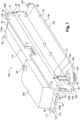
- FIG. 1 is a partial perspective view of a cooling element 100 of an electrical storage device 200 for a motor vehicle.
- Such a cooling element 100 is intended to support a plurality of electrical storage devices 200, only one of which is shown for reasons of clarity. This cooling element 100 and the electrical storage devices 200 that it supports form a heat treatment system within the meaning of the invention.
- the cooling element 100 illustrated in the figure 1 comprises at least a first wall 110 and a second wall 120 integral with each other and arranged perpendicularly with respect to each other.
- the first wall 110 extends mainly in a first plane perpendicular to a second plane in which the second wall 120 mainly extends.
- Each wall 110, 120 respectively comprises an inner face 111, 121 and an outer face 112, 122 oriented respectively towards the electrical storage device 200, or opposite this electrical storage device 200.
- Each of the inner faces 111, 121 is configured to receive one or more electrical storage devices 200 thermally coupled thereto.
- the electrical storage device(s) 200 are secured to the inner faces 111, 121 by means of fixing means 20 so that the latter are in thermal contact therewith.
- the first wall 110 includes a first channel 113 for the circulation of a heat transfer fluid and the second wall 120 includes a second channel 123 for the circulation of a heat transfer fluid.
- Each channel 113, 123 for circulating a heat transfer fluid is respectively formed in the thickness of the wall 110, 120, the channels 113, 123 extending parallel to one another.
- the cooling element 100 may comprise other walls in which extend one or more channels for circulation of a heat transfer fluid and on which are secured one or more electrical storage devices.
- the walls of the cooling element 100 thus perform a heat exchanger function in addition to a structural function. In this sense, these walls may hereinafter be called “support and thermal regulation walls”.
- the walls 110, 120 form two separate support and heat exchange (notably cooling) planes with electrical storage devices.
- each electrical storage device 200 is configured to be in thermal contact both with the first wall 110 of the cooling element 100 and with the second wall 120 of this cooling element 100.
- an electrical storage device is in thermal contact with only one wall, in this case the first wall 110, of the cooling element.
- the longitudinal ends of the first and second channels 113, 123 open respectively through an opening on two opposite edges 110a, 110b, 120a, 120b of the first and second walls 110, 120.
- Each opening is closed by a closure plug 30 flush with the flat surface of the corresponding edge 110a, 110b, 120a, 120b.
- the cooling element 100 comprises a connection flange 400 configured to supply heat transfer fluid to the internal circulation circuit of the cooling element and to evacuate the heat transfer fluid coming from this internal circulation circuit of the cooling element. cooling.
- connection flange 400 is mounted on the outer face of a third wall 130 extending the second wall 120 of the cooling element 100 and extending perpendicular to the latter.
- connection flange 400 will be described in more detail later in relation to the figures 3 to 5 .
- first and second channels 113, 123 are fluidically connected by means of fluidic connection means 150 .
- These fluidic connection means 150 visible on the figure 1 And 2 , allow the heat transfer fluid to flow from the first channel 113 of the first wall 110 to the second channel 123 of the second wall 120, and vice versa.
- At least one fluid circulation channel in this case the second channel 123 on the figure 1 , is fluidically connected to the connection flange 400 by means of fluidic supply and evacuation pipes 160, 161 making it possible to supply heat transfer fluid to the channels 113, 123 and to evacuate the heat transfer fluid from these channels ( figure 1 And 2 ).
- the electrical storage devices can be fixed on the inner face 111 of the first horizontal wall 110 and on the inner face 121 of the second vertical wall 120 by means of fixing means 20.
- the terms “horizontal” and “vertical” must here be understood relative to an orientation of the cooling element 100 when it is mounted on the vehicle for which it is intended.
- the fixing means 20 of the electrical storage devices on the inner faces 111, 121 are fixing studs of cylindrical shape.
- the fixing studs are screwed into the walls of the cooling element 100.
- each electrical storage device is fixed to a wall of the cooling element 100 by means of four studs 20.
- the number and the distribution of the pads on the cooling element 100 can be adapted according to the shape of the electrical storage devices.
- the inner face 131 of the third horizontal wall 130 is not intended to support any electrical module(s).
- fluidic connection means 150 are formed in the thickness of the walls 110, 120 so as to allow the heat transfer fluid to flow from the first channel 113 to the second channel 123, and vice versa.
- Such a configuration makes it possible to reduce the bulk of the cooling element 100 and to minimize the risks of leaks by dispensing with the implementation of external connectors.
- the fluidic connection means 150 are located close to each longitudinal end of the walls 110, 120 as can be seen on the figure 1 .
- connection means 150 here comprises several parallel ducts 114 made in the first wall 110 and extending transversely to the first channel 113, and a recess 126 made in the second wall 120, above the second channel 123.
- the recess 126 is configured to fluidically connect the second channel 123 to the conduits 114 opening into the first channel 113 and into the recess 126.
- first and second channels 113, 123 are closed off by means of sealing plugs 30 which are flush with the edges of the cooling element 100.
- the second wall 120 comprises a recess 127 closed off by a sealed closure plug 32 which is intended to form a sealed internal partition dividing the second channel 123 into two parts 123a, 123b fluidically isolated from one another.
- the recess 127 is located between the two recesses 126 of the fluid connection means 150 .
- Such a recess can easily be produced by machining, in particular on an extruded profile.
- the fluidic connection means can thus connect at least two channels formed in the same wall (or the same plane) of the cooling element, or two channels formed in two distinct walls (or distinct planes) of the cooling element. They are obtained by machining (drilling or grooving, for example).
- the cooling element 100 comprises a port 160 for supplying heat transfer fluid to the first part 123a of the second channel 123 and a port 161 for discharging heat transfer fluid from the second part 123b of the second channel 123.
- Each supply and evacuation port 160, 161 respectively comprises circulation pipes 124, 124', 125, 125', formed in the thickness of the second wall 120, and cavities 124", 125", formed in the third wall 130 of the cooling element 100.
- the pipes 124, 124', 125, 125' are configured to respectively connect the first and second parts 123a, 123b of the second channel 123 to the connection flange 400.
- the circulation pipes 124, 124', 125, 125' form, on the one hand, supply pipes 124, 124' for heat transfer fluid and, on the other hand, evacuation pipes 125, 125' for this same fluid, or Conversely.
- the supply lines 124, 124' are fluidically connected to the first part 123a of the second channel 123 and the discharge lines 125, 125' are fluidically connected to the second part 123b of the second channel 123.
- the supply 124, 124' and evacuation 125, 125' pipes are respectively located on either side of the recess 127 closed off by the closure plug 32.
- the cavities 124", 125" which have a substantially parallelepipedic shape, communicate respectively with the supply 124, 124' and evacuation 125, 125' pipes.
- Such a configuration makes it possible to minimize the bulk of the cooling element 100 and to minimize the risks of leaks by doing away with pipes external to the walls.
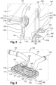
- the cooling element 100 carries on one of its outer faces a connection flange 400 configured to ensure the connection/fluidic connection between pipes 423, 424 for supplying and discharging heat transfer fluid external to the cooling element 100 and the circulation circuit extending within the cooling element 100.
- this circulation circuit within the cooling element comprises several circulation channels for a heat transfer fluid provided in one or more walls of the cooling element 100.
- connection flange 400 is intended to allow the connection between a thermal management circuit of the vehicle and the battery pack.
- connection flange 400 is mounted, in a sealed manner, on an outer surface of the cooling element 100.
- connection flange 400 is fixed on the outer face 132 of the third support wall 130 of the box 100.
- connection flange 400 comprises a rectangular base 410 fixed to the third wall 130 and a parallelepipedic cover 420 which is placed on the base 410.
- the base 410 has a male fluidic inlet element 411 and a male fluidic outlet 412 element.
- the male fluid inlet and outlet elements 411, 412 protrude perpendicularly from the upper surface 416 of the base 410 and each have a cylindrical inner orifice opening out so as to allow the passage of a heat transfer fluid.
- the male fluid inlet and outlet elements 411, 412 are configured to be inserted respectively into female fluid inlet and outlet elements 421, 422 carried by the cover 420 of the connection flange 400.
- the male 411, 412 and female 421, 422 elements have complementary shapes.
- the female fluid inlet and outlet elements 421, 422 are respectively secured by gluing or brazing at one end of the pipes 423, 424 heat transfer fluid supply (from the thermal management circuit of the vehicle) and evacuation of the heat transfer fluid (to the thermal management circuit of the vehicle).
- the other end of the pipes 423, 424 is intended to be connected to a flexible polymer pipe, EPDM for example, or to receive a quick connection device.
- the ends of the pipes 423, 424 emerging inside the cover 420 are oriented perpendicular to the male fluid inlet and outlet elements 411, 412, which makes it possible to minimize the size of the connection flange 400.
- the male fluid inlet and outlet elements 411, 412 each carry a sealing gasket 413, 414, such as an O-ring or a flat seal, which is arranged in a circular groove made on the outer surface of each element.
- the gaskets 413, 414 seal ensure the seal between the male 411, 412 and female 421, 422 elements, and therefore between the base 410 and the cover 420 of the flange 400 during operation of the battery pack.
- the base 410 of the flange 400 is pressed against the third support wall 130 of the box 100 and is secured to the latter by means of fixing screws 500.
- the base 410 of the flange 400 comprises tapped holes 4101 configured to receive fixing screws 501 of the cover 420 on the base 410.
- the tapped holes 4101 are aligned in this example and arranged between the male fluid input and output elements 411, 412.
- the upper surface 416 of the base 410 carries a seal 418 arranged in a groove 417 provided on the periphery thereof.
- heat treatment system means a system comprising at least the cooling element 100 on which is arranged at least one electrical storage device 200.
- this seal 418 is crushed by the cover C of the receiver box of the heat treatment system.
- the lower surface 415 of the base 410 intended to be in contact with the cooling element 100
- the upper surface 416 intended to be in contact with the cover 420 of the flange 400
- connection flange 400 allows the connection flange 400 to ensure an optimal electrical connection between the cooling element 100 and the receiving box of the heat treatment system in the event of failure of one of the electrical modules.
- the contact surface between the cooling element 100 and the connecting flange 400 must be large enough so that the electrical resistance between them is negligible compared to the electrical resistance between the cooling element 100 and the heat treatment system receiving box.
- the base 410 of the connection flange 400 is made of aluminum or any other conductive material.
- seals 419 located on the periphery of the cavities 124", 125" so as to ensure sealing between the third wall of the cooling element 100 and the flange 400 of connection.
- the 400 connection flange ensures the fluidic connection between the conduits outside the cooling element 100 and the internal circuit extending into the walls of the cooling element 100 of the electrical storage device.
- connection flange determines the orientation of the fluid inlets and outlets. It is mechanically fixed to the cooling element 100. In other words, its fixing does not require brazing.
- cooling element according to the invention may not implement a connection flange as described previously, but connection ducts bonded or welded to the outer surface of the cooling element.
- the cooling element and the closure caps are made of aluminum.
- the cooling element is obtained by extrusion so that it can have complex shapes and improved mechanical strength.
- Closing plugs are, for example, matted plugs, plugs with or without tenon, welded plugs, glued plugs, or plugs made of elastomer, in particular EPDM, press-fitted.
- the plugs are flush with the edges of the cooling element so as to minimize the size of the latter.
- the interior wall of the circulation channels is smooth.
- the internal walls of the channels have reliefs (studs, for example) so as to increase the heat exchange surface and therefore the heat transfer between the electrical modules and the heat transfer fluid circulating within the walls of the the cooling element.
- the number and dimensions of the reliefs are a compromise between thermal performance and pressure drop of the heat transfer fluid in the channels.
- each circulation channel may have multiple internal channels.
- the heat transfer fluid used in the cooling element according to the invention can be glycol water or a coolant liquid, in particular R134a or 1234YF.
- Each support and heat exchange wall comprises one or more coolant fluid circulation channels.
- the number of channels per wall depends in particular on the dimensions of the electrical modules and their power.
- the same electrical module is in contact with at least two walls of the cooling element.
- the third wall 130 comprises a third fluid circulation channel fluidly connected to the second channel 123 or to the connection flange 400 .
- One or more walls of the cooling element can comprise several circulation channels fluidically coupled by means of connections made in the thickness of the wall.
- the cooling element comprises three support and thermal regulation walls, two walls of which are parallel to each other and are integral with each other by means of a wall s extending perpendicular thereto, so that the cooling element has a "U" shaped cross section.
- each face of at least one wall of the cooling element is intended to support electrical storage devices.
- the base of the connection flange comprises the female elements and the cover of the connection flange carries the male elements.
- the cooling element carries two connecting flanges each comprising a single male or female element.
- the cover of the connecting flange is produced by a plastic injection process.
- connection flange does not fulfill the function of electrical continuity ("potential equalization") and does not ensure electrical connection between the cooling element and the receiving box of the heat treatment system.
Claims (10)
- Kühlelement (100) einer elektrischen Speichervorrichtung (200) für ein Kraftfahrzeug, beinhaltend mindestens eine erste Wand (110), die sich im Wesentlichen in einer ersten Ebene erstreckt und in der mindestens ein erster Kanal (113) eingerichtet ist, und mindestens eine zweite Wand (120), die sich im Wesentlichen in einer zweiten Ebene erstreckt und in der mindestens ein zweiter Kanal (123) eingerichtet ist, wobei der erste Kanal (113) und der zweite Kanal (123) dazu fähig sind, von einem Wärmeträgerfluid durchflossen zu werden, dadurch gekennzeichnet, dass sich die erste Ebene, in der sich die erste Wand (110) erstreckt, und die zweite Ebene, in der sich die zweite Wand (120) erstreckt, schneiden und dass mindestens die erste Wand (110) dazu konfiguriert ist, die elektrische Speichervorrichtung (200) zu tragen, und dass das Kühlelement Fluidverbindungsmittel beinhaltet, die dazu konfiguriert sind, den ersten Kanal, der in der ersten Wand eingerichtet ist, mit dem zweiten Kanal, der in der zweiten Wand eingerichtet ist, zu verbinden, wobei jedes Fluidverbindungsmittel innerhalb der ersten und zweiten Wand eingerichtet ist.
- Kühlelement (100) nach dem vorhergehenden Anspruch, wobei die elektrische Speichervorrichtung (200) mit der ersten Wand (110) und der zweiten Wand (120) in Kontakt angeordnet ist.
- Kühlelement (100) nach einem beliebigen der vorhergehenden Ansprüche, wobei die erste Ebene, in der sich die erste Wand im Wesentlichen erstreckt (110), und die zweite Ebene, in der sich die zweite Wand (120) im Wesentlichen erstreckt, senkrecht zueinander sind.
- Kühlelement (100) nach einem beliebigen der vorhergehenden Ansprüche, dadurch gekennzeichnet, dass es Fluidverbindungsmittel (150) beinhaltet, die dazu konfiguriert sind, den ersten Kanal (113), der in der ersten Wand (110) eingerichtet ist, mit dem zweiten Kanal (123), der in der zweiten Wand (120) eingerichtet ist, zu verbinden, wobei jedes Fluidverbindungsmittel (150) innerhalb der ersten und zweiten Wand (110, 120) eingerichtet ist.
- Kühlelement (100) nach einem beliebigen der vorhergehenden Ansprüche, das mindestens eine erste Leitung (124, 124', 125, 125'), die dazu bestimmt ist, den ersten und/oder den zweiten Kanal (113, 123) mit Wärmeträgerfluid zu versorgen, und mindestens eine zweite Leitung (124, 124', 125, 125'), die dazu bestimmt ist, das Wärmeträgerfluid, das in dem ersten und/oder dem zweiten Kanal (113, 123) strömt, abzuführen, beinhaltet, wobei die erste Leitung (124, 124', 125, 125') und die zweite Leitung (124, 124', 125, 125') in der zweiten Wand (120) des Kühlelements (100) eingerichtet sind.
- Kühlelement (100) nach dem vorhergehenden Anspruch, das mindestens einen Fluidanschlussflansch (400) beinhaltet, der dazu konfiguriert ist, das Kühlelement (100) mittels der ersten und/oder der zweiten Leitung (124, 124', 125, 125') an einen externen Kreislauf anzuschließen.
- Kühlelement (100) nach einem beliebigen der vorhergehenden Ansprüche in Kombination mit Anspruch 6, das eine dritte Wand (130) beinhaltet, die sich im Wesentlichen in einer dritten Ebene erstreckt, wobei diese dritte Ebene zu der ersten Ebene, in der sich die erste Wand (110) erstreckt, parallel ist und die zweite Ebene, in der sich die zweite Wand (120) befindet, schneidet, wobei der Fluidanschlussflansch (400) an dieser dritten Wand (130) befestigt ist.
- Kühlelement (100) nach einem beliebigen der vorhergehenden Ansprüche, dadurch gekennzeichnet, dass die Enden des ersten und zweiten Kanals (113, 123) an zwei gegenüberliegenden Rändern (110a, 110b, 120a, 120b) der ersten und zweiten Wand (110, 120) münden und dazu bestimmt sind, durch Verschlussmittel (30) abgedichtet zu sein.
- Kühlelement (100) nach einem beliebigen der vorhergehenden Ansprüche, dadurch gekennzeichnet, dass es durch Extrusion erhalten wird.
- Wärmebehandlungssystem (1) für ein Kraftfahrzeug, das mindestens eine elektrische Speichervorrichtung (200) beinhaltet, die durch mindestens ein Kühlelement (100) nach einem beliebigen der vorhergehenden Ansprüche getragen wird.
Applications Claiming Priority (2)
| Application Number | Priority Date | Filing Date | Title |
|---|---|---|---|
| FR1762576A FR3075470B1 (fr) | 2017-12-20 | 2017-12-20 | Element de refroidissement d'un dispositif de stockage electrique pour vehicule automobile. |
| PCT/FR2018/053492 WO2019122771A1 (fr) | 2017-12-20 | 2018-12-20 | Élément de refroidissement d'un dispositif de stockage électrique pour véhicule automobile |
Publications (2)
| Publication Number | Publication Date |
|---|---|
| EP3707772A1 EP3707772A1 (de) | 2020-09-16 |
| EP3707772B1 true EP3707772B1 (de) | 2023-05-24 |
Family
ID=62017397
Family Applications (1)
| Application Number | Title | Priority Date | Filing Date |
|---|---|---|---|
| EP18847237.7A Active EP3707772B1 (de) | 2017-12-20 | 2018-12-20 | Kühlelement einer elektrischen speichervorrichtung für ein kraftfahrzeug |
Country Status (5)
| Country | Link |
|---|---|
| US (1) | US20210143496A1 (de) |
| EP (1) | EP3707772B1 (de) |
| CN (1) | CN111742439A (de) |
| FR (1) | FR3075470B1 (de) |
| WO (1) | WO2019122771A1 (de) |
Family Cites Families (9)
| Publication number | Priority date | Publication date | Assignee | Title |
|---|---|---|---|---|
| US5460900A (en) * | 1994-08-08 | 1995-10-24 | Gnb Battery Technologies Inc. | Lead-acid battery having a fluid compartment for reducing convection-induced heat transfer |
| KR20140015257A (ko) * | 2010-09-02 | 2014-02-06 | 아카솔 게엠베하 | 냉각 모듈의 제조를 위한 방법 및 냉각 모듈 |
| DE102011084660B4 (de) * | 2011-10-18 | 2018-02-15 | Bayerische Motoren Werke Aktiengesellschaft | Vorrichtung zur Spannungsversorgung |
| EP2629594A1 (de) * | 2012-02-14 | 2013-08-21 | ABB Oy | Elektronische Vorrichtung |
| CN104471784B (zh) * | 2012-05-17 | 2016-12-28 | 日立汽车系统株式会社 | 电池组件 |
| DE102012214783A1 (de) * | 2012-08-20 | 2014-02-20 | Behr Gmbh & Co. Kg | Wärmetauscher für eine Batterieeinheit |
| DE102013219200A1 (de) * | 2013-09-24 | 2015-03-26 | Behr Gmbh & Co. Kg | Kühleinrichtung für ein Batteriesystem, insbesondere eines Kraftfahrzeugs |
| EP3062381B1 (de) * | 2015-02-26 | 2018-04-11 | Magneti Marelli S.p.A. | Kühlkreislauf mit kühlflüssigkeit für lithiumbatterien und fahrzeug mit dem kühlkreislauf |
| KR102259414B1 (ko) * | 2015-11-20 | 2021-06-01 | 주식회사 엘지에너지솔루션 | 히트싱크 및 이를 포함하는 배터리 모듈 |
-
2017
- 2017-12-20 FR FR1762576A patent/FR3075470B1/fr active Active
-
2018
- 2018-12-20 CN CN201880089771.9A patent/CN111742439A/zh active Pending
- 2018-12-20 EP EP18847237.7A patent/EP3707772B1/de active Active
- 2018-12-20 WO PCT/FR2018/053492 patent/WO2019122771A1/fr unknown
- 2018-12-20 US US16/956,373 patent/US20210143496A1/en active Pending
Also Published As
| Publication number | Publication date |
|---|---|
| WO2019122771A1 (fr) | 2019-06-27 |
| FR3075470B1 (fr) | 2021-07-30 |
| FR3075470A1 (fr) | 2019-06-21 |
| CN111742439A (zh) | 2020-10-02 |
| EP3707772A1 (de) | 2020-09-16 |
| US20210143496A1 (en) | 2021-05-13 |
Similar Documents
| Publication | Publication Date | Title |
|---|---|---|
| EP3776687B1 (de) | Batterieeinheit mit integrierten mitteln zur temperatursteuerung | |
| EP4062120B1 (de) | Thermisches managementsystem für eine elektrische komponente | |
| EP4005008B1 (de) | Batteriekühlmodul und vorrichtung sowie entsprechende batterie | |
| EP4121711B1 (de) | Vorrichtung zur thermischen regelung mindestens eines elektronischen bauteils | |
| EP3461297A1 (de) | Vorrichtung zur kühlung von batterien und zugehöriges herstellungsverfahren | |
| EP3707772B1 (de) | Kühlelement einer elektrischen speichervorrichtung für ein kraftfahrzeug | |
| EP3278393B1 (de) | Batteriemodul, insbesondere für ein kraftfahrzeug, und entsprechender wärmetauscher für ein batteriemodul | |
| FR3067171A1 (fr) | Dispositif de regulation thermique de cellules de stockage d’energie electrique d'un pack-batterie de grande surface | |
| EP3925018A1 (de) | Batterieeinheit und kraftfahrzeug mit mindestens einer solchen einheit | |
| WO2020254757A1 (fr) | Echangeur thermique a circulation de liquide et connecteur pour un tel échangeur | |
| WO2020025869A1 (fr) | Élément de régulation thermique d'un composant électrique, d'un véhicule automobile, susceptible de dégager de la chaleur lors de son fonctionnement | |
| WO2019229355A1 (fr) | Dispositif de refroidissement de batteries et procédé de fabrication correspondant | |
| WO2020099810A1 (fr) | Compartiment pour module de stockage d'energie electrique pour vehicule automobile | |
| EP3769025A2 (de) | Wärmetauscher mit verbindungskanälen zum zu- und abführen eines wärmetransferfluids | |
| FR3081545A1 (fr) | Dispositif de refroidissement de batteries et procede de fabrication correspondant | |
| FR3077127A1 (fr) | Echangeur thermique, notamment pour la regulation thermique de batteries | |
| WO2020094984A1 (fr) | Ensemble de refroisissement, notamment pour batterie de vehicule | |
| WO2021048499A1 (fr) | Dispositif de gestion thermique pour composant électrique et système comprenant un tel dispositif | |
| WO2022268587A1 (fr) | Dispositif de régulation thermique pour système électronique | |
| FR3104893A1 (fr) | « Dispositif de régulation thermique d’au moins un composant électrique » | |
| WO2020065236A1 (fr) | Dispositif de gestion thermique d'un dispositif de stockage électrique pour véhicule automobile | |
| FR3094842A1 (fr) | Corps de régulation thermique d’un dispositif de stockage d’énergie de véhicule automobile électrique ou hybride | |
| FR3088587A1 (fr) | Compartiment pour module de stockage d'energie electrique pour vehicule automobile | |
| FR3086049A1 (fr) | Dispositif de gestion thermique d’un dispositif de stockage electrique pour vehicule automobile |
Legal Events
| Date | Code | Title | Description |
|---|---|---|---|
| STAA | Information on the status of an ep patent application or granted ep patent |
Free format text: STATUS: UNKNOWN |
|
| STAA | Information on the status of an ep patent application or granted ep patent |
Free format text: STATUS: THE INTERNATIONAL PUBLICATION HAS BEEN MADE |
|
| PUAI | Public reference made under article 153(3) epc to a published international application that has entered the european phase |
Free format text: ORIGINAL CODE: 0009012 |
|
| STAA | Information on the status of an ep patent application or granted ep patent |
Free format text: STATUS: REQUEST FOR EXAMINATION WAS MADE |
|
| 17P | Request for examination filed |
Effective date: 20200612 |
|
| AK | Designated contracting states |
Kind code of ref document: A1 Designated state(s): AL AT BE BG CH CY CZ DE DK EE ES FI FR GB GR HR HU IE IS IT LI LT LU LV MC MK MT NL NO PL PT RO RS SE SI SK SM TR |
|
| AX | Request for extension of the european patent |
Extension state: BA ME |
|
| DAV | Request for validation of the european patent (deleted) | ||
| DAX | Request for extension of the european patent (deleted) | ||
| STAA | Information on the status of an ep patent application or granted ep patent |
Free format text: STATUS: EXAMINATION IS IN PROGRESS |
|
| 17Q | First examination report despatched |
Effective date: 20211001 |
|
| GRAP | Despatch of communication of intention to grant a patent |
Free format text: ORIGINAL CODE: EPIDOSNIGR1 |
|
| STAA | Information on the status of an ep patent application or granted ep patent |
Free format text: STATUS: GRANT OF PATENT IS INTENDED |
|
| INTG | Intention to grant announced |
Effective date: 20221213 |
|
| RAP3 | Party data changed (applicant data changed or rights of an application transferred) |
Owner name: VALEO SYSTEMES THERMIQUES |
|
| GRAS | Grant fee paid |
Free format text: ORIGINAL CODE: EPIDOSNIGR3 |
|
| GRAA | (expected) grant |
Free format text: ORIGINAL CODE: 0009210 |
|
| STAA | Information on the status of an ep patent application or granted ep patent |
Free format text: STATUS: THE PATENT HAS BEEN GRANTED |
|
| AK | Designated contracting states |
Kind code of ref document: B1 Designated state(s): AL AT BE BG CH CY CZ DE DK EE ES FI FR GB GR HR HU IE IS IT LI LT LU LV MC MK MT NL NO PL PT RO RS SE SI SK SM TR |
|
| REG | Reference to a national code |
Ref country code: GB Ref legal event code: FG4D Free format text: NOT ENGLISH |
|
| REG | Reference to a national code |
Ref country code: CH Ref legal event code: EP |
|
| REG | Reference to a national code |
Ref country code: DE Ref legal event code: R096 Ref document number: 602018050299 Country of ref document: DE |
|
| REG | Reference to a national code |
Ref country code: AT Ref legal event code: REF Ref document number: 1570114 Country of ref document: AT Kind code of ref document: T Effective date: 20230615 |
|
| REG | Reference to a national code |
Ref country code: IE Ref legal event code: FG4D Free format text: LANGUAGE OF EP DOCUMENT: FRENCH |
|
| P01 | Opt-out of the competence of the unified patent court (upc) registered |
Effective date: 20230528 |
|
| REG | Reference to a national code |
Ref country code: LT Ref legal event code: MG9D |
|
| REG | Reference to a national code |
Ref country code: NL Ref legal event code: MP Effective date: 20230524 |
|
| REG | Reference to a national code |
Ref country code: AT Ref legal event code: MK05 Ref document number: 1570114 Country of ref document: AT Kind code of ref document: T Effective date: 20230524 |
|
| PG25 | Lapsed in a contracting state [announced via postgrant information from national office to epo] |
Ref country code: SE Free format text: LAPSE BECAUSE OF FAILURE TO SUBMIT A TRANSLATION OF THE DESCRIPTION OR TO PAY THE FEE WITHIN THE PRESCRIBED TIME-LIMIT Effective date: 20230524 Ref country code: PT Free format text: LAPSE BECAUSE OF FAILURE TO SUBMIT A TRANSLATION OF THE DESCRIPTION OR TO PAY THE FEE WITHIN THE PRESCRIBED TIME-LIMIT Effective date: 20230925 Ref country code: NO Free format text: LAPSE BECAUSE OF FAILURE TO SUBMIT A TRANSLATION OF THE DESCRIPTION OR TO PAY THE FEE WITHIN THE PRESCRIBED TIME-LIMIT Effective date: 20230824 Ref country code: NL Free format text: LAPSE BECAUSE OF FAILURE TO SUBMIT A TRANSLATION OF THE DESCRIPTION OR TO PAY THE FEE WITHIN THE PRESCRIBED TIME-LIMIT Effective date: 20230524 Ref country code: ES Free format text: LAPSE BECAUSE OF FAILURE TO SUBMIT A TRANSLATION OF THE DESCRIPTION OR TO PAY THE FEE WITHIN THE PRESCRIBED TIME-LIMIT Effective date: 20230524 Ref country code: AT Free format text: LAPSE BECAUSE OF FAILURE TO SUBMIT A TRANSLATION OF THE DESCRIPTION OR TO PAY THE FEE WITHIN THE PRESCRIBED TIME-LIMIT Effective date: 20230524 |
|
| PG25 | Lapsed in a contracting state [announced via postgrant information from national office to epo] |
Ref country code: RS Free format text: LAPSE BECAUSE OF FAILURE TO SUBMIT A TRANSLATION OF THE DESCRIPTION OR TO PAY THE FEE WITHIN THE PRESCRIBED TIME-LIMIT Effective date: 20230524 Ref country code: PL Free format text: LAPSE BECAUSE OF FAILURE TO SUBMIT A TRANSLATION OF THE DESCRIPTION OR TO PAY THE FEE WITHIN THE PRESCRIBED TIME-LIMIT Effective date: 20230524 Ref country code: LV Free format text: LAPSE BECAUSE OF FAILURE TO SUBMIT A TRANSLATION OF THE DESCRIPTION OR TO PAY THE FEE WITHIN THE PRESCRIBED TIME-LIMIT Effective date: 20230524 Ref country code: LT Free format text: LAPSE BECAUSE OF FAILURE TO SUBMIT A TRANSLATION OF THE DESCRIPTION OR TO PAY THE FEE WITHIN THE PRESCRIBED TIME-LIMIT Effective date: 20230524 Ref country code: IS Free format text: LAPSE BECAUSE OF FAILURE TO SUBMIT A TRANSLATION OF THE DESCRIPTION OR TO PAY THE FEE WITHIN THE PRESCRIBED TIME-LIMIT Effective date: 20230924 Ref country code: HR Free format text: LAPSE BECAUSE OF FAILURE TO SUBMIT A TRANSLATION OF THE DESCRIPTION OR TO PAY THE FEE WITHIN THE PRESCRIBED TIME-LIMIT Effective date: 20230524 Ref country code: GR Free format text: LAPSE BECAUSE OF FAILURE TO SUBMIT A TRANSLATION OF THE DESCRIPTION OR TO PAY THE FEE WITHIN THE PRESCRIBED TIME-LIMIT Effective date: 20230825 |
|
| PG25 | Lapsed in a contracting state [announced via postgrant information from national office to epo] |
Ref country code: FI Free format text: LAPSE BECAUSE OF FAILURE TO SUBMIT A TRANSLATION OF THE DESCRIPTION OR TO PAY THE FEE WITHIN THE PRESCRIBED TIME-LIMIT Effective date: 20230524 |
|
| PG25 | Lapsed in a contracting state [announced via postgrant information from national office to epo] |
Ref country code: SK Free format text: LAPSE BECAUSE OF FAILURE TO SUBMIT A TRANSLATION OF THE DESCRIPTION OR TO PAY THE FEE WITHIN THE PRESCRIBED TIME-LIMIT Effective date: 20230524 |
|
| PG25 | Lapsed in a contracting state [announced via postgrant information from national office to epo] |
Ref country code: SM Free format text: LAPSE BECAUSE OF FAILURE TO SUBMIT A TRANSLATION OF THE DESCRIPTION OR TO PAY THE FEE WITHIN THE PRESCRIBED TIME-LIMIT Effective date: 20230524 Ref country code: SK Free format text: LAPSE BECAUSE OF FAILURE TO SUBMIT A TRANSLATION OF THE DESCRIPTION OR TO PAY THE FEE WITHIN THE PRESCRIBED TIME-LIMIT Effective date: 20230524 Ref country code: RO Free format text: LAPSE BECAUSE OF FAILURE TO SUBMIT A TRANSLATION OF THE DESCRIPTION OR TO PAY THE FEE WITHIN THE PRESCRIBED TIME-LIMIT Effective date: 20230524 Ref country code: EE Free format text: LAPSE BECAUSE OF FAILURE TO SUBMIT A TRANSLATION OF THE DESCRIPTION OR TO PAY THE FEE WITHIN THE PRESCRIBED TIME-LIMIT Effective date: 20230524 Ref country code: DK Free format text: LAPSE BECAUSE OF FAILURE TO SUBMIT A TRANSLATION OF THE DESCRIPTION OR TO PAY THE FEE WITHIN THE PRESCRIBED TIME-LIMIT Effective date: 20230524 Ref country code: CZ Free format text: LAPSE BECAUSE OF FAILURE TO SUBMIT A TRANSLATION OF THE DESCRIPTION OR TO PAY THE FEE WITHIN THE PRESCRIBED TIME-LIMIT Effective date: 20230524 |
|
| PGFP | Annual fee paid to national office [announced via postgrant information from national office to epo] |
Ref country code: FR Payment date: 20231220 Year of fee payment: 6 Ref country code: DE Payment date: 20231208 Year of fee payment: 6 |
|
| REG | Reference to a national code |
Ref country code: DE Ref legal event code: R097 Ref document number: 602018050299 Country of ref document: DE |
|
| PLBE | No opposition filed within time limit |
Free format text: ORIGINAL CODE: 0009261 |
|
| STAA | Information on the status of an ep patent application or granted ep patent |
Free format text: STATUS: NO OPPOSITION FILED WITHIN TIME LIMIT |
|
| 26N | No opposition filed |
Effective date: 20240227 |
|
| PG25 | Lapsed in a contracting state [announced via postgrant information from national office to epo] |
Ref country code: SI Free format text: LAPSE BECAUSE OF FAILURE TO SUBMIT A TRANSLATION OF THE DESCRIPTION OR TO PAY THE FEE WITHIN THE PRESCRIBED TIME-LIMIT Effective date: 20230524 |