EP4005008B1 - Batteriekühlmodul und vorrichtung sowie entsprechende batterie - Google Patents
Batteriekühlmodul und vorrichtung sowie entsprechende batterie Download PDFInfo
- Publication number
- EP4005008B1 EP4005008B1 EP20744079.3A EP20744079A EP4005008B1 EP 4005008 B1 EP4005008 B1 EP 4005008B1 EP 20744079 A EP20744079 A EP 20744079A EP 4005008 B1 EP4005008 B1 EP 4005008B1
- Authority
- EP
- European Patent Office
- Prior art keywords
- duct
- plate
- baseplate
- circuit
- evacuation
- Prior art date
- Legal status (The legal status is an assumption and is not a legal conclusion. Google has not performed a legal analysis and makes no representation as to the accuracy of the status listed.)
- Active
Links
- 238000001816 cooling Methods 0.000 title claims description 58
- 239000002131 composite material Substances 0.000 claims description 30
- 230000015572 biosynthetic process Effects 0.000 claims description 28
- 238000005755 formation reaction Methods 0.000 claims description 28
- 239000000463 material Substances 0.000 claims description 23
- 239000012530 fluid Substances 0.000 claims description 22
- 239000013529 heat transfer fluid Substances 0.000 claims description 14
- 230000002093 peripheral effect Effects 0.000 claims description 10
- 229910052782 aluminium Inorganic materials 0.000 claims description 7
- XAGFODPZIPBFFR-UHFFFAOYSA-N aluminium Chemical compound [Al] XAGFODPZIPBFFR-UHFFFAOYSA-N 0.000 claims description 7
- 239000007788 liquid Substances 0.000 claims description 7
- 229910052751 metal Inorganic materials 0.000 claims description 7
- 239000002184 metal Substances 0.000 claims description 7
- 238000003466 welding Methods 0.000 claims description 5
- 230000000295 complement effect Effects 0.000 claims description 4
- 238000007599 discharging Methods 0.000 claims description 4
- 239000000853 adhesive Substances 0.000 claims description 2
- 230000001070 adhesive effect Effects 0.000 claims description 2
- 230000006835 compression Effects 0.000 claims description 2
- 238000007906 compression Methods 0.000 claims description 2
- 230000008878 coupling Effects 0.000 claims description 2
- 238000010168 coupling process Methods 0.000 claims description 2
- 238000005859 coupling reaction Methods 0.000 claims description 2
- 239000012815 thermoplastic material Substances 0.000 claims description 2
- 239000003351 stiffener Substances 0.000 claims 1
- 238000004519 manufacturing process Methods 0.000 description 9
- 238000012546 transfer Methods 0.000 description 5
- 238000010276 construction Methods 0.000 description 3
- 239000004033 plastic Substances 0.000 description 3
- 238000013461 design Methods 0.000 description 2
- 238000009826 distribution Methods 0.000 description 2
- 239000005022 packaging material Substances 0.000 description 2
- 230000001681 protective effect Effects 0.000 description 2
- 238000007789 sealing Methods 0.000 description 2
- 239000002470 thermal conductor Substances 0.000 description 2
- 206010001488 Aggression Diseases 0.000 description 1
- 208000031968 Cadaver Diseases 0.000 description 1
- 229920012563 PP GF30 Polymers 0.000 description 1
- 229910000831 Steel Inorganic materials 0.000 description 1
- 230000006978 adaptation Effects 0.000 description 1
- 239000000654 additive Substances 0.000 description 1
- 230000000996 additive effect Effects 0.000 description 1
- 238000004026 adhesive bonding Methods 0.000 description 1
- 230000016571 aggressive behavior Effects 0.000 description 1
- 230000032683 aging Effects 0.000 description 1
- 239000004411 aluminium Substances 0.000 description 1
- 230000009286 beneficial effect Effects 0.000 description 1
- 239000002826 coolant Substances 0.000 description 1
- 230000007797 corrosion Effects 0.000 description 1
- 238000005260 corrosion Methods 0.000 description 1
- 230000007547 defect Effects 0.000 description 1
- 238000011161 development Methods 0.000 description 1
- 230000018109 developmental process Effects 0.000 description 1
- 239000006185 dispersion Substances 0.000 description 1
- 238000009434 installation Methods 0.000 description 1
- 238000009413 insulation Methods 0.000 description 1
- 229910001416 lithium ion Inorganic materials 0.000 description 1
- 238000012423 maintenance Methods 0.000 description 1
- 239000007769 metal material Substances 0.000 description 1
- 238000012986 modification Methods 0.000 description 1
- 230000004048 modification Effects 0.000 description 1
- 229920000642 polymer Polymers 0.000 description 1
- 229920001296 polysiloxane Polymers 0.000 description 1
- 230000000284 resting effect Effects 0.000 description 1
- 239000010959 steel Substances 0.000 description 1
- 238000003860 storage Methods 0.000 description 1
- 238000006467 substitution reaction Methods 0.000 description 1
- 229920001169 thermoplastic Polymers 0.000 description 1
- 229920001187 thermosetting polymer Polymers 0.000 description 1
- 239000004416 thermosoftening plastic Substances 0.000 description 1
- 230000008719 thickening Effects 0.000 description 1
Images


Classifications
-
- H—ELECTRICITY
- H01—ELECTRIC ELEMENTS
- H01M—PROCESSES OR MEANS, e.g. BATTERIES, FOR THE DIRECT CONVERSION OF CHEMICAL ENERGY INTO ELECTRICAL ENERGY
- H01M10/00—Secondary cells; Manufacture thereof
- H01M10/60—Heating or cooling; Temperature control
- H01M10/65—Means for temperature control structurally associated with the cells
- H01M10/656—Means for temperature control structurally associated with the cells characterised by the type of heat-exchange fluid
- H01M10/6567—Liquids
- H01M10/6568—Liquids characterised by flow circuits, e.g. loops, located externally to the cells or cell casings
-
- H—ELECTRICITY
- H01—ELECTRIC ELEMENTS
- H01M—PROCESSES OR MEANS, e.g. BATTERIES, FOR THE DIRECT CONVERSION OF CHEMICAL ENERGY INTO ELECTRICAL ENERGY
- H01M10/00—Secondary cells; Manufacture thereof
- H01M10/60—Heating or cooling; Temperature control
- H01M10/61—Types of temperature control
- H01M10/613—Cooling or keeping cold
-
- H—ELECTRICITY
- H01—ELECTRIC ELEMENTS
- H01M—PROCESSES OR MEANS, e.g. BATTERIES, FOR THE DIRECT CONVERSION OF CHEMICAL ENERGY INTO ELECTRICAL ENERGY
- H01M10/00—Secondary cells; Manufacture thereof
- H01M10/60—Heating or cooling; Temperature control
- H01M10/62—Heating or cooling; Temperature control specially adapted for specific applications
- H01M10/625—Vehicles
-
- H—ELECTRICITY
- H01—ELECTRIC ELEMENTS
- H01M—PROCESSES OR MEANS, e.g. BATTERIES, FOR THE DIRECT CONVERSION OF CHEMICAL ENERGY INTO ELECTRICAL ENERGY
- H01M10/00—Secondary cells; Manufacture thereof
- H01M10/60—Heating or cooling; Temperature control
- H01M10/65—Means for temperature control structurally associated with the cells
- H01M10/655—Solid structures for heat exchange or heat conduction
- H01M10/6554—Rods or plates
-
- H—ELECTRICITY
- H01—ELECTRIC ELEMENTS
- H01M—PROCESSES OR MEANS, e.g. BATTERIES, FOR THE DIRECT CONVERSION OF CHEMICAL ENERGY INTO ELECTRICAL ENERGY
- H01M10/00—Secondary cells; Manufacture thereof
- H01M10/60—Heating or cooling; Temperature control
- H01M10/65—Means for temperature control structurally associated with the cells
- H01M10/655—Solid structures for heat exchange or heat conduction
- H01M10/6556—Solid parts with flow channel passages or pipes for heat exchange
-
- H—ELECTRICITY
- H01—ELECTRIC ELEMENTS
- H01M—PROCESSES OR MEANS, e.g. BATTERIES, FOR THE DIRECT CONVERSION OF CHEMICAL ENERGY INTO ELECTRICAL ENERGY
- H01M10/00—Secondary cells; Manufacture thereof
- H01M10/60—Heating or cooling; Temperature control
- H01M10/65—Means for temperature control structurally associated with the cells
- H01M10/656—Means for temperature control structurally associated with the cells characterised by the type of heat-exchange fluid
- H01M10/6567—Liquids
-
- H—ELECTRICITY
- H01—ELECTRIC ELEMENTS
- H01M—PROCESSES OR MEANS, e.g. BATTERIES, FOR THE DIRECT CONVERSION OF CHEMICAL ENERGY INTO ELECTRICAL ENERGY
- H01M50/00—Constructional details or processes of manufacture of the non-active parts of electrochemical cells other than fuel cells, e.g. hybrid cells
- H01M50/20—Mountings; Secondary casings or frames; Racks, modules or packs; Suspension devices; Shock absorbers; Transport or carrying devices; Holders
-
- H—ELECTRICITY
- H01—ELECTRIC ELEMENTS
- H01M—PROCESSES OR MEANS, e.g. BATTERIES, FOR THE DIRECT CONVERSION OF CHEMICAL ENERGY INTO ELECTRICAL ENERGY
- H01M2220/00—Batteries for particular applications
- H01M2220/20—Batteries in motive systems, e.g. vehicle, ship, plane
-
- Y—GENERAL TAGGING OF NEW TECHNOLOGICAL DEVELOPMENTS; GENERAL TAGGING OF CROSS-SECTIONAL TECHNOLOGIES SPANNING OVER SEVERAL SECTIONS OF THE IPC; TECHNICAL SUBJECTS COVERED BY FORMER USPC CROSS-REFERENCE ART COLLECTIONS [XRACs] AND DIGESTS
- Y02—TECHNOLOGIES OR APPLICATIONS FOR MITIGATION OR ADAPTATION AGAINST CLIMATE CHANGE
- Y02E—REDUCTION OF GREENHOUSE GAS [GHG] EMISSIONS, RELATED TO ENERGY GENERATION, TRANSMISSION OR DISTRIBUTION
- Y02E60/00—Enabling technologies; Technologies with a potential or indirect contribution to GHG emissions mitigation
- Y02E60/10—Energy storage using batteries
Definitions
- the present invention relates to the field of autonomous electrical energy sources, in particular those on board motor vehicles, of the battery unit type with integrated temperature control or regulation means, has as its objects a cooling module for the cells of such a battery, a battery unit comprising such modules and a hybrid or electric motor vehicle comprising at least one such unit.
- Hybrid/electric vehicles are equipped with a battery to store the electrical energy necessary for their operation.
- Current challenges require optimizing the design of battery units, also known as “battery packs”, in order to obtain the best performance in terms of lifespan (charge/discharge) and running time.
- the batteries used ideally need to operate at temperatures between 10° C. and 30° C., in particular batteries with high storage density, of the Li-ion or Li-polymer type for example.
- a temperature that is too low affects the autonomy and a temperature that is too high affects the life of the batteries. It is therefore necessary to better regulate the temperature of such batteries.
- the housings for receiving these batteries can currently be made directly by a part of the vehicle or consist of cavities formed in a structural part of this vehicle.
- these solutions are very inflexible in terms of installation and make maintenance difficult. Autonomous battery pack solutions that are not integrated into the structure of the vehicle are therefore to be preferred.
- the housing of the battery unit of these known solutions being made of metal (preferably aluminum), it cannot thermally and electrically insulate the battery pack from the outside, moreover has a high cost price. and is also subject to corrosion.
- a battery cooling system with a plurality of cooling plates each connected by a pair of elbow tubular connectors with common lines for supplying and discharging heat transfer fluid in the form of an extruded aluminum profile having two longitudinal chambers to which the fittings are connected.
- CN 209 056 573 U discloses a cooling module for electric vehicle battery cells or modules, comprising a main body in the form of a rectangular composite plate and integrating a circuit for the circulation of a heat transfer fluid with a fluid inlet and outlet, the composite plate comprising a base plate, in which a network of channels are provided, and a cover plate, which is attached to the base plate with the production of a peripheral seal, which forms by cooperation with the channels of the base plate conduits and which is intended to come into surface contact with the cells of the battery to be cooled.
- a battery module comprising a main plate on which cells are positioned.
- the main plate has along one of its lateral sides a formation which is prominent and inclined with respect to this plate.
- DE 10 2015 115138 A1 discloses a battery for a vehicle with a casing formed by two parts. Each part has a main plate with a cooling channel and a perpendicular plate.
- the object of the invention is to overcome at least the main limitations of the state of the art mentioned above.
- the subject of the invention is a cooling module for cells or module(s) of an electric battery, in particular of a hybrid vehicle battery. or electric, comprising a main body in the form of a composite plate preferably of rectangular shape and integrating at least one circuit for the circulation of a heat transfer fluid with a fluid inlet and an outlet, this composite plate comprising a base plate made of a material rigid structure with low thermal conductivity, in which a network of channels are provided, and at least one cover plate made of a material with high thermal conductivity, which is attached to the base plate with the production of an at least peripheral seal, which forms by cooperation with the channels of the base plate the duct(s) or duct segments(s) of the circuit(s) and which is intended to come into surface contact with cells or at least one module of the battery to be cooled, each set [plate of cover/conduit circuit] forming a temperature-controlled reception site, module characterized in that it also comprises, along one of the lateral sides of the composite plate, a formation which is prominent and inclined with
- the invention also relates to a cooling device comprising at least two aforementioned modules, a battery unit integrating cooling modules of the aforementioned type and a motor vehicle comprising at least one such battery.
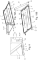
- THE figures 1 to 9 illustrate, in the form of different constructive variants, a cooling module 1 for cells or module(s) 2 of an electric battery 2', in particular of a hybrid or electric vehicle battery, comprising a main body 3 in the form of a composite plate preferably of rectangular in shape and integrating at least one circuit 4 for the circulation of a heat transfer fluid with a fluid inlet 5 and an outlet 5', this composite plate 3 comprising a base plate 6 made of a rigid material with low thermal conductivity, in which are formed a network of channels 7, and at least one cover plate 8 in a material with high thermal conductivity, which is attached to the base plate 6 with the production of an at least peripheral seal 9, which forms by cooperation with the channels 7 of base plate 6 conduit(s) 4 or conduit segments 4' of circuit(s) and which is intended to come into surface contact with cells or at least one module 2 of the battery 2' to be cooled, each assembly [cover plate 8/conduit circuit(s) 4] forming a temperature-controlled receiving site 1'.
- said module 1 also comprises, along one of the lateral sides 3' of the composite plate 3, a formation 10 which is prominent and inclined with respect to said composite plate 3, which incorporates portions of Supply and evacuation pipe(s) 11, 11' connected respectively to the fluid inlet 5 and to the outlet 5' of the or each of the circuit(s) of pipe(s) 4 of the composite plate 3 , which is made of a material with low thermal conductivity, and of which at least a part, preferably a major part 12 comprising channels 11" corresponding to the portions of supply duct(s) 11 and evacuation 11 ', is made in one piece with the base plate 6 of the main body 3.
- a formation 10 which is prominent and inclined with respect to said composite plate 3, which incorporates portions of Supply and evacuation pipe(s) 11, 11' connected respectively to the fluid inlet 5 and to the outlet 5' of the or each of the circuit(s) of pipe(s) 4 of the composite plate 3 , which is made of a material with low thermal conductivity, and of which at least a part, preferably a major part
- a cooling module 1 in which the possibility of heat exchange between the fluid and the external environment is concentrated at the level of the cover plate(s) 8 on which the cells, arranged in one or more module(s) 2. Moreover, not only the integrated circuit(s) 4 bringing the heat transfer fluid into contact with the plate(s) 8 (through segments of ducts 4' interposed between the plates 6 and 8) are structurally integrated into the module 1, but also the portions of ducts 11 and 11' ensuring the fluidic connection between the circuit(s) 4 and the external lines supply and evacuation 18, 18 '.
- any specific connection of duct or tube at the level of module 1 is avoided, the exposure of the circulation paths is limited, and the fluidic connection of module 1 with the outside is made at one end of the latter, outside from the reception area of the cells or modules 2 (cleared reception space) and at a distance (height offset) relative to the support plane provided by the or each cover plate 8.
- an intrinsically good thermal conductor material metal plate for example
- the low thermal conductivity it can be achieved by using a material that is weakly thermally conductive, or even thermally insulating, in combination with a relatively large thickness of the wall of the surface element 9.
- high thermal conductivity ⁇ herein means values of ⁇ such that ⁇ > 50 Wm -1 .K -1 , preferably ⁇ > 100 Wm -1 .K -1 and by low thermal conductivity ⁇ , values ⁇ such that ⁇ 1 Wm -1 .K -1 , preferably ⁇ ⁇ 0.5 Wm -1 .K -1 .
- the material with good thermal conductivity has a conductivity between 100 W/m/K and 300 W/m/K, typically 200 W/m/K like aluminum.
- the low thermal conductivity material has a conductivity between 0.05 W/m/K and 0.5 W/m/K, typically 0.2 W/m/K like plastic type PP GF30.
- the greater the difference in thermal conductivity between the cover plate 8 (with high thermal conductivity - for example plate made of thin metallic material) and the base plate 6 (with low thermal conductivity - for example thick plastic material wall) will be important, the more the beneficial effect of the invention will be important.
- the material of the cover plate 8 preferably aluminum, can also be non-metallic, and for example consist of a thermoplastic or thermoset material, loaded with additive to increase its thermal conductivity.
- the cover plate 8 can, as a variant, also be of a flexible or flexible nature in order to adapt and compensate for the flatness defects of the modules, while being a good thermal conductor (silicone for example, preferably filled).
- the prominent formation 10 is in the form of a plate portion extending substantially perpendicularly to the median plane PM of the composite plate 3 and continuously extending a side edge 6' of the base plate 6, preferably a corresponding edge to a width of the rectangle formed by the composite plate 3.
- the formation 10 constitutes a side wall with respect to the plate 3, these two elements together forming an angle structure, with L-section, which can be easily accommodated in a box by resting on the bottom of the latter and being wedged against a side wall of said housing.
- the protruding formation 10 is provided, at the level of the ends of the portions of supply and evacuation duct(s) 11, 11', which are located opposite their ends communicating with the fluid inlet 5 and outlet 5' of the or each circuit of conduit(s) 4 integrated into the composite plate 3, supply and evacuation ports or fittings 13, 13' offset with respect to the median plane PM of the composite plate 3, advantageously located at a distance above the cover plate 8 concerned and emerging laterally from said formation 10, for example from a lateral edge of the latter ( figure 1 , 6 And 10 ).
- the protruding formation 10 integrating portions of the supply 11 and evacuation 11 'duct(s) and having an overall constitution in the form of a plate portion, has a composite structure and comprises a base body 12 in which are made channels 11" corresponding to the portions of supply 11 and evacuation 11' duct(s) and a complementary plate 12' delimiting by cooperation with said channels 11 "said portions of duct(s) 11 and 11', the end pieces or inlet 13 and outlet 13' ports of the latter emerging laterally at the level of an edge of said plate portion 10 ( figures 6B , 7A , 8 , 9 And 10A ).
- the lateral side 3' presenting the prominent formation 10 in the form of a wall or plate portion is one of the short sides of said rectangle.
- This wall or plate portion 10 integrating the conduit portions 11 and 11' may have a length equal to or less than the dimension of the lateral side 3', depending on the size imposed, the fluidic connection requirements, the economy of material or similar.
- the plate 10 which can also serve as a structural element, an abutment and/or a lateral support for the cooling module 1 and possibly as a stop wall for the cells, can be a separate part attached to a side of the base plate 6 and made integral with it by interlocking, gluing, welding or other, with the production of a seal between the inlet/outlet 5, 5' and the conduit portions 11, 11'.
- the base plate 6 and the base body 12 (of the composite plate 10) consist of a one-piece part 19 molded in thermoplastic material, the or each cover plate 8 consisting of a metal plate, preferably aluminum.
- the formation 10 in the form of a plate or a wall can have different shapes and variable contours, by necessity, by saving material, by constructive ease or by concern for size.
- the upper edge of this formation can be straight (that is to say parallel to the median plane of the main body 3 - cf. figure 1 ), be inclined (cf. figure 6 , 9 And 10 ) or any shape. Also, it can be bare or equipped with additional functional accessories.
- the protruding formation 10 preferably in the form of a plate or a vertical wall, to comprise or be provided with a plate 21, configured to support an electronic card 21', forming for example part of a management system battery 2 ', an electrical connection cable 21 "or the like.
- the module 1 can comprise at least two distinct reception sites 1' controlled in temperature, each site 1' comprising a cover plate 8 and an associated circuit 4 of fluid circulation conduits, the various circuits 4 being either fluidically connected in series and together to a single pair of portions of supply 11 and evacuation 11' ducts, or each connected separately and independently to a specific pair of portions of supply 11 and evacuation 11' ducts.
- the module 1 may comprise a single cover plate 8 and a single circuit of fluid circulation ducts 4, together forming a single temperature-controlled reception site 1', on which one or more module(s) is intended to bear. ) battery 2.
- each circuit 4 of conduit(s) for circulating heat transfer fluid FC associated with a thermally conductive cover plate 8 is composed of flat conduit segments 4' fluidically connected in series to constitute a serpentine-shaped arrangement between the inlet 5 and the outlet 5' of the circuit 4.
- the set of conduit segments 4' of the circuit 4 thus forms a space of surface circulation and flattened in the form of a blade between the base 6 and cover 8 plates, with a substantially continuous surface extension with the exception of the compartmentation walls 4" defining the fluid circulation path in the circuit 4 considered ( Figures 6C, 7A, 7B , 10A and 10B ).
- the or each cover plate 8 is secured at least peripherally, continuously or not, by means of a material, adhesive or mechanical bond 14 or even by welding, to the base plate 6, with production of a continuous liquid seal 9 around the circuit of duct(s) 4 associated with the cover plate 8 in question, for example by placing a compression seal 9 between the latter and the base plate 6.
- the or each cover plate 8 may comprise an edge 8' forming a peripheral frame, in one piece or attached, in particular by overmolding, and which is secured to the base plate 6, said edge 8' being advantageously made in one material allowing welding (for example by vibration, laser, hot gas or the like) with said base plate 6, the cover plate 8 in question being, where appropriate, also secured with the base plate 6 in at least one place at inside the frame 8', for example at the level of a compartmentalization wall 4" of said base plate 6.
- the invention can provide, as shown for example by the figure 2 And 7B , that a leakage path 15 is associated with each reception site 1', said leakage path 15 comprising a groove or a collecting channel 15' with peripheral circumferential extension and at least one evacuation passage 15" opening onto the face of the base plate 6 opposite the cover plate 8.
- the channel or groove 15" extends between the sealing 9 and the peripheral link 14 existing between the base 6 and cover 8 plates, the leakage path 15 being preferably formed and located entirely in the base plate. 6.
- the base plate 6 can be provided with fixing sites 16, such as for example holes, eyelets or the like. , formed in the body of said plate 6 or in lugs 16 'projecting laterally.
- cooling modules 1 when several cooling modules 1 must be installed in the same casing 20, it may be advantageous to rigidly connect them together to form a structural unit, in addition to a functional unit.
- a rigid construction of the composite plate 3 is also desirable for reliable support over time, and without damage in the event of impact, of the modules 2'.
- the base plate 6 may include means 16" for mechanical coupling with at least one other module 1 (for example mutually nestable complementary formations, cooperating fixing lugs or the like) and/or be provided with formations of stiffening 6" on its underside opposite to the cover plate(s) 8 (ribs, wings, thickenings).
- at least one other module 1 for example mutually nestable complementary formations, cooperating fixing lugs or the like
- stiffening 6" on its underside opposite to the cover plate(s) 8 (ribs, wings, thickenings).
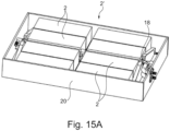
- a subject of the invention is also, as illustrated by way of examples on the Figures 3A, 3B And 11 to 14 , a cooling device 17 for battery 2' comprising a plurality of cells, preferably grouped into modules 2, said device 17 having a plurality of temperature-controlled reception sites 1', on which the cells rest, these sites 1' all being connected to supply and evacuation ducts 18, 18' which can be connected to a heat transfer fluid circulation circuit FC.
- This device 17 is characterized in that it has a modular construction and comprises at least two cooling modules (1) as described above.
- this device 17 comprises four cooling modules 1 arranged in two columns and two rows of two, in such a way that the prominent formations 10 of two modules 1 are each time coplanar and that the ports 13, 13' at the inlet and outlet of their respective duct portions 11 and 11' are located opposite each other, the two pairs of aligned protruding formations 10 of the two pairs of modules 1 being located at mutually opposites of said arrangement of modules 1.
- the supply and evacuation ducts 18 and 18' connect the portions of conduit(s) 11, 11' for supply and evacuation of the various cooling modules 1 to one another and to a fluid circulation circuit external heat carrier (not shown), by forming a supply line and an evacuation line, each conduit 18, 18' being equipped with connection end pieces 18" coming into sealed engagement in the inlet and outlet ports 13 , 13' of the various cooling modules 1, for example by interlocking.
- Connection means endpieces 18'" or other) for connecting these ducts 18, 18' to the external circuit (not shown) are of course also provided.
- the supply duct and/or the evacuation duct 18 , 18′ preferably each of the two, consists of two parts of ducts 22 aligned and connected by an axially sliding and sealed connection 22′, for example equipped with at least one O-ring (cf. figure 12C And 15B ).
- An arrangement of cooling modules 1 to form a cooling device 17 as shown in the figure 11 , 12 And 14 makes it possible to enclose the cells and battery modules 2 in a holding structure in the casing 20 (lower tray) and insulation (thermal, physical) with respect to the latter, as shown by the figures 11 to 15 , while allowing with a standard basic element (module 1 - declined for example in two variants with different inclinations of the upper edges of the formations 10) a constructive modularity with flexibility of adaptation in terms of size and configuration.
- a battery unit can comprise only one cooling device 17.
- several separate cooling devices can be provided, which can be fluidly connected to one another.
- At least one of the supply and/or evacuation conduits 18, 18', preferably both, is (are) provided with an end piece 23 for connection to an additional circulation circuit , if necessary to another cooling device 17.
- the invention also relates to a temperature-managed battery unit 2', comprising cells grouped together in a plurality of battery modules 2 and a protective casing 20 (only its lower tray is shown, which is closed by an upper cover not shown ).
- This battery unit is characterized in that it also comprises at least one cooling device 17 as described above, mounted in the casing 20 and having a plurality of cooling modules 1, preferably four, advantageously connected mechanically and fluidically. between them, and providing a plurality of receiving sites 1' for said battery modules 2.
- the box 20 may in particular comprise a sealed container (cf. figures 15A And 15B ) to contain any leaks of heat transfer liquid FC, while having passages (if necessary sealed) for the connection of the fluid circulation lines to the conduits 18, 18 ', preferably at the level of a side wall of the tank of the housing 20, away from the bottom.
- a sealed container cf. figures 15A And 15B
- FC heat transfer liquid
- the invention also relates to a motor vehicle, in particular electric or hybrid, characterized in that it comprises at least one battery unit 2' of the type mentioned above, the or each cooling device 17 of which is connected to the engine cooling circuit of said vehicle.
Landscapes
- Chemical & Material Sciences (AREA)
- Chemical Kinetics & Catalysis (AREA)
- Electrochemistry (AREA)
- General Chemical & Material Sciences (AREA)
- Engineering & Computer Science (AREA)
- Manufacturing & Machinery (AREA)
- Secondary Cells (AREA)
- Battery Mounting, Suspending (AREA)
Claims (21)
- Kühlmodul (1) für Zellen oder Modul (e) (2) einer elektrischen Batterie (2'), insbesondere einer Batterie eines Hybrid- oder Elektrofahrzeugs, umfassend eine Hauptkörper (3) in Form einer Verbundplatte, die vorzugsweise rechteckig geformt ist und wenigstens einen Kreislauf (4) für die Zirkulation eines Wärmeübertragungsfluids (FC) mit einem Fluidein- (5) und -auslass (5') enthält, wobei diese Verbundplatte (3) eine Grundplatte (6) aus einem starren Material mit geringer Wärmeleitfähigkeit, in der ein Netz aus Kanälen (7) ausgebildet ist, und wenigstens eine Abdeckplatte (8) aus einem Material mit erhöhter Wärmeleitfähigkeit umfasst, die auf die Grundplatte (6) aufgesetzt ist, unter Herstellung einer Abdichtung wenigstens am Umfang (9), die durch Zusammenwirkung mit den Kanälen (7) der Grundplatte (6) die Leitung(en) (4) oder Leitungssegmente (4') des Kreislaufs oder der Kreisläufe bildet, und die dazu bestimmt ist, mit Zellen oder wenigstens einem Modul (2) der zu kühlenden Batterie (2') in Oberflächenkontakt zu treten, wobei jede Einheit aus Abdeckplatte (8) und Leitungskreislauf eine temperaturgesteuerte Aufnahmestelle (1') bildet,
wobei das Modul (1) dadurch gekennzeichnet ist, dass es ebenfalls entlang einer der Seitenflächen (3') der Verbundplatte (3) ein Gebilde (10) umfasst, das im Verhältnis zur Verbundplatte (3) vorsteht und geneigt ist, das Zu- und Ablaufleitungsabschnitte (11, 11') enthält, die jeweils mit dem Fluidein- (5) und -auslass (5') des Kreislaufs oder jedes der Kreisläufe von Leitung(en) (4) der Verbundplatte (3) verbunden sind, das aus einem Material mit geringer Wärmeleitfähigkeit hergestellt ist, und wovon wenigstens ein Abschnitt, vorzugsweise ein bedeutender Abschnitt (12), der Kanäle (11") umfasst, die den Zu- (11) und Ablaufleitungsabschnitten (11') entsprechen, mit der Grundplatte (6) des Hauptkörpers (3) einstückig ausgebildet ist. - Modul nach Anspruch 1, dadurch gekennzeichnet, dass das vorstehende Gebilde (10) in Form eines Plattenabschnitts vorliegt, der sich senkrecht zur Mittelebene (PM) der Verbundplatte (3) erstreckt und eine Seitenkante (6') der Grundplatte (6), vorzugsweise eine Kante, die einer Breite des Rechtecks entspricht, das von der Verbundplatte (3) gebildet ist, durchgehend verlängert.
- Modul nach Anspruch 1 oder 2, dadurch gekennzeichnet, dass das vorstehende Gebilde (10) an den Enden der Zu- und Ablaufleitungsabschnitte (11, 11'), die sich gegenüber von ihren Enden befinden, die mit dem Fluidein-(5) und -auslass (5') des oder jedes Kreislaufs von Leitung(en) (4) in Verbindung stehen, der in die Verbundplatte (3) integriert ist, mit Ports oder Ansatzstücken zur Versorgung und zum Ablauf (13, 13') versehen ist, die im Verhältnis zur Mittelebene (PM) der Verbundplatte (3) versetzt sind, die sich vorteilhafterweise in einem Abstand über der betreffenden Abdeckplatte (8) befinden und seitlich von dem Gebilde (10) münden, zum Beispiel von einer Seitenkante desselben.
- Modul nach einem der Ansprüche 1 bis 3, dadurch gekennzeichnet, dass das vorstehende Gebilde (10), das Zu- (11) und Ablaufleitungsabschnitte (11') enthält und eine plattenabschnittförmige Gesamtbeschaffenheit aufweist, eine Verbundstruktur aufweist und einen Grundkörper (12), in dem Kanäle (11") ausgebildet sind, die den Zu- (11) und Ablaufleitungsabschnitten (11') entsprechen, und eine ergänzende Platte (12') umfasst, die durch Zusammenwirkung mit den Kanälen (11") die Leitungsabschnitte (11 und 11') begrenzt, wobei die Ansatzstücke oder Ports zum Ein- (13) und Auslass (13') derselben seitlich an einer Kante des Plattenabschnitts (10) münden.
- Modul nach einem der Ansprüche 1 bis 4, dadurch gekennzeichnet, dass jeder Leitungskreislauf (4) zur Zirkulation von Wärmeübertragungsfluid, der einer wärmeleitenden Abdeckplatte (8) zugeordnet ist, aus flachen Leitungssegmenten (4') zusammengesetzt ist, die in Reihe fluidisch verbunden sind, um eine serpentinenförmige Anordnung zwischen dem Einlass (5) und dem Auslass (5') des Kreislaufs (4) zu bilden, wobei sämtliche Leitungssegmente (4') des Kreislaufs (4) einen flächigen und abgeflachten Zirkulationsraum in Form eines Blatts zwischen der Grund- (6) und der Abdeckplatte (8) bilden, mit einer durchgehenden Flächenerstreckung mit Ausnahme der Trennwände (4"), die den Fluidzirkulationsweg im betreffenden Kreislauf (4) definieren.
- Modul nach einem der Ansprüche 1 bis 5, dadurch gekennzeichnet, dass die oder jede Abdeckplatte (8) wenigstens am Umfang, durchgehend oder nicht, mittels einer stoffschlüssigen, Haft- oder mechanischen oder auch Schweißverbindung (14) fest mit der Grundplatte (6) verbunden ist, mit Herstellung einer durchgehenden Flüssigkeitsabdichtung (9) um den Leitungskreislauf (4), der der betreffenden Abdeckplatte (8) zugeordnet ist, zum Beispiel durch Einsatz einer Kompressionsdichtung (9) zwischen dieser und der Grundplatte (6).
- Modul nach Anspruch 6, dadurch gekennzeichnet, dass die oder jede Abdeckplatte (8) einen Rand (8') aufweist, der einen umlaufenden Rahmen bildet, der einstückig ausgebildet oder angesetzt ist, insbesondere durch Anspritzen, und der fest mit der Grundplatte (6) verbunden ist, wobei der Rand (8') vorteilhafterweise aus einem Material hergestellt ist, das eine Verschweißung mit der Grundplatte (6) gestattet, wobei die Abdeckplatte (8) gegebenenfalls ebenfalls an wenigstens einer Stelle im Inneren des Rahmens (8') fest mit der Grundplatte (6) verbunden ist, zum Beispiel an einer Trennwand (4") der Grundplatte (6).
- Modul nach einem der Ansprüche 1 bis 7, dadurch gekennzeichnet, dass ein Leckageweg (15) jeder Aufnahmestelle (1') zugeordnet ist, wobei der Leckageweg (15) eine Sammelrille oder einen Sammelkanal (15') mit umlaufender Umfangserstreckung und wenigstens einen Ablaufdurchlass (15") umfasst, der auf der Seite der Grundplatte (6) mündet, die der Abdeckplatte (8) gegenüberliegt.
- Modul nach den Ansprüchen 6 und 8, dadurch gekennzeichnet, dass sich der Kanal oder die Rille (15") zwischen der Abdichtung (9) und der Umfangsverbindung (14) erstreckt, die zwischen der Grund- (6) und der Abdeckplatte (8) besteht, wobei der Leckageweg (15) vorzugsweise vollständig in der Grundplatte (6) ausgebildet und angeordnet ist.
- Modul nach einem der Ansprüche 1 bis 9, dadurch gekennzeichnet, dass es eine einzelne Abdeckplatte (8) und einen einzelnen fluidischen Zirkulationsleitungskreislauf (4) umfasst, die zusammen eine einzelne temperaturgesteuerte Aufnahmestelle (1') bilden, auf der ein oder mehrere Batteriemodul(e) (2) aufliegen soll.
- Modul nach einem der Ansprüche 1 bis 9, dadurch gekennzeichnet, dass es wenigstens zwei gesonderte temperaturgesteuerte Aufnahmestellen (1') aufweist, wobei jede Stelle (1') eine Abdeckplatte (8) und einen zugeordneten fluidischen Zirkulationsleitungskreislauf (4) umfasst, wobei die verschiedenen Kreisläufe (4) entweder fluidisch in Reihe und zusammen mit einem einzelnen Paar von Zu- (11) und Ablaufleitungsabschnitten (11') verbunden sind oder jeweils getrennt und unabhängig mit einem eigenen Paar von Zu- (11) und Ablaufleitungsabschnitten (11') verbunden sind.
- Modul nach einem der Ansprüche 1 bis 11, dadurch gekennzeichnet, dass die Grundplatte (6) mit Befestigungsstellen (16), wie zum Beispiel Bohrungen, Ösen oder Ähnlichem, die im Körper der Platte (6) oder in seitlich hervorstehenden Laschen (16') ausgebildet sind, und gegebenenfalls mit Mitteln (16") zur mechanischen Kopplung mit wenigstens einem anderen Modul (1) und/oder Versteifungsgebilden (6") auf ihrer Unterseite gegenüber der oder den Abdeckplatte(n) (8) versehen ist.
- Modul nach Anspruch 4, dadurch gekennzeichnet, dass die Grundplatte (6) und der Grundkörper (12) aus einem einstückigen Teil (19) bestehen, das aus thermoplastischem Material geformt ist, wobei die oder jede Abdeckplatte (8) aus einer Metallplatte besteht, vorzugsweise aus Aluminium.
- Modul nach einem der Ansprüche 1 bis 13, dadurch gekennzeichnet, dass das vorstehende Gebilde (10), vorzugsweise in Form einer vertikalen Platte oder Wand, eine Trägerplatte (21) umfasst oder damit versehen ist, die dazu ausgebildet ist, eine Leiterplatte (21'), die zum Beispiel Teil eines Systems zur Verwaltung der Batterie (2') ist, ein elektrisches Anschlusskabel (21") oder Ähnliches zu tragen.
- Kühlvorrichtung (17) für eine Batterie (2'), die eine Mehrzahl von Zellen umfasst, die vorzugsweise zu Modulen (2) gruppiert sind, wobei die Vorrichtung (17) eine Mehrzahl von temperaturgesteuerten Aufnahmestellen (1') aufweist, auf denen die Zellen aufliegen, wobei diese Stellen (1') alle mit Versorgungs- und Ablaufleitungen (18, 18') verbunden sind, die an einen Kreislauf zur Zirkulation von Wärmeübertragungsfluid (FC) angeschlossen werden können, wobei die Vorrichtung (17) dadurch gekennzeichnet ist, dass sie einen modularen Aufbau aufweist und wenigstens zwei Kühlmodule (1) nach einem der Ansprüche 1 bis 14 umfasst.
- Kühlvorrichtung nach Anspruch 15, dadurch gekennzeichnet, dass sie vier Kühlmodule (1) umfasst, die in zwei Spalten und zwei Zweierreihen angeordnet sind, so dass die vorstehenden Gebilde (10) zweier Module (1) jedes Mal komplanar sind und die Ein- und Auslassports (13, 13') ihrer jeweiligen Leitungsabschnitte (11 und 11') einander zugewandt sind, wobei sich die zwei Paare von in Reihe angeordneten vorstehenden Gebilden (10) der zwei Paare von Modulen (1) an einander gegenüberliegen Seiten der Anordnung von Modulen (1) befinden.
- Kühlvorrichtung nach einem der Ansprüche 15 und 16, dadurch gekennzeichnet, dass die Versorgungs- und Ablaufleitungen (18 und 18') die Zu- und Ablaufleitungsabschnitte (11, 11') der verschiedenen Kühlmodule (1) miteinander und mit einem externen Wärmeübertragungsfluid-Zirkulationskreislauf verbinden, wobei eine Versorgungsleitung und eine Ablaufleitung gebildet wird, wobei jede Leitung (18, 18') mit Anschlussstücken (18") ausgestattet ist, die in den Ein- und Auslassports (13, 13') der verschiedenen Kühlmodule (1) dicht in Eingriff stehen, zum Beispiel durch Stecken.
- Kühlvorrichtung nach einem der Ansprüche 15 bis 17, dadurch gekennzeichnet, dass die Versorgungsleitung und/oder die Ablaufleitung (18, 18'), vorzugsweise jede der beiden, von zwei Leitungsabschnitten (22) gebildet ist, die in Reihe angeordnet und durch eine axial gleitende und dichte Verbindung (22') verbunden sind, die zum Beispiel mit wenigstens einer Ringdichtung ausgestattet ist.
- Kühlvorrichtung nach einem der Ansprüche 15 bis 18, dadurch gekennzeichnet, dass wenigstens eine von der Versorgungs- und/oder Ablaufleitung (18, 18'), vorzugsweise beide, mit einem Ansatzstück (23) zum Anschluss an einen Nebenzirkulationskreislauf, gegebenenfalls an eine andere Kühlvorrichtung (17), versehen ist bzw. sind.
- Temperaturgesteuerte Batterieeinheit (2'), die Zellen, die zu einer Mehrzahl von Batteriemodulen (2) gruppiert sind, und ein Schutzgehäuse (20) umfasst, wobei die Einheit dadurch gekennzeichnet ist, dass sie ebenfalls wenigstens eine Kühlvorrichtung (17) nach einem der Ansprüche 15 bis 19 umfasst, die im Gehäuse (20) angebracht ist und eine Mehrzahl von Kühlmodulen (1) aufweist, vorzugsweise vier, die vorteilhafterweise mechanisch und fluidisch miteinander verbunden sind und eine Mehrzahl von Aufnahmestellen (1') für die Batteriemodule (2) bereitstellen.
- Kraftfahrzeug, insbesondere Elektro- oder Hybrid-Kraftfahrzeug, dadurch gekennzeichnet, dass es wenigstens eine Batterieeinheit (2') nach Anspruch 20 umfasst, von welcher eine oder jede Kühlvorrichtung (17) mit dem Motor-Kühlkreislauf des Fahrzeugs verbunden ist.
Applications Claiming Priority (2)
| Application Number | Priority Date | Filing Date | Title |
|---|---|---|---|
| FR1908679A FR3099646B1 (fr) | 2019-07-30 | 2019-07-30 | Module et dispositif de refroidissement pour batterie et batterie correspondante |
| PCT/EP2020/071396 WO2021018961A1 (fr) | 2019-07-30 | 2020-07-29 | Module et dispositif de refroidissement pour batterie et batterie correspondante |
Publications (2)
| Publication Number | Publication Date |
|---|---|
| EP4005008A1 EP4005008A1 (de) | 2022-06-01 |
| EP4005008B1 true EP4005008B1 (de) | 2023-07-19 |
Family
ID=69172864
Family Applications (1)
| Application Number | Title | Priority Date | Filing Date |
|---|---|---|---|
| EP20744079.3A Active EP4005008B1 (de) | 2019-07-30 | 2020-07-29 | Batteriekühlmodul und vorrichtung sowie entsprechende batterie |
Country Status (5)
| Country | Link |
|---|---|
| US (1) | US20220278393A1 (de) |
| EP (1) | EP4005008B1 (de) |
| CN (1) | CN114175361A (de) |
| FR (1) | FR3099646B1 (de) |
| WO (1) | WO2021018961A1 (de) |
Families Citing this family (3)
| Publication number | Priority date | Publication date | Assignee | Title |
|---|---|---|---|---|
| FR3113450B1 (fr) * | 2020-08-13 | 2023-10-06 | Valeo Siemens Eautomotive France Sas | Ensemble électrique modulaire comprenant un système de refroidissement intégré |
| FR3133911B1 (fr) * | 2022-03-23 | 2024-03-15 | Valeo Systemes Thermiques | Dispositif de regulation thermique d’un organe de stockage d’energie electrique |
| WO2023232047A1 (zh) * | 2022-05-31 | 2023-12-07 | 瑞浦兰钧能源股份有限公司 | 电池包液冷板及电池包 |
Family Cites Families (13)
| Publication number | Priority date | Publication date | Assignee | Title |
|---|---|---|---|---|
| FR3003938A1 (fr) | 2013-03-29 | 2014-10-03 | Valeo Systemes Thermiques | Plaque d'echange thermique pour gestion thermique de batterie et procede de fabrication associe. |
| DE102013207592B3 (de) * | 2013-04-25 | 2014-08-07 | Magna Steyr Battery Systems Gmbh & Co Og | Batteriesystem |
| US9543557B2 (en) * | 2014-09-26 | 2017-01-10 | Ford Global Technologies, Llc | Traction battery assembly |
| KR102120118B1 (ko) * | 2016-08-18 | 2020-06-08 | 주식회사 엘지화학 | 배터리 모듈 |
| KR102207881B1 (ko) * | 2017-01-17 | 2021-01-25 | 주식회사 엘지화학 | 배터리 모듈, 이러한 배터리 모듈을 포함하는 배터리 팩 및 이러한 배터리 팩을 포함하는 자동차 |
| US20200395644A1 (en) | 2017-08-30 | 2020-12-17 | Modine Manufacturing Company | Battery cooling system |
| DE102017215609A1 (de) * | 2017-09-05 | 2019-03-07 | Mahle International Gmbh | Batteriegehäuse für eine Traktionsbatterie |
| KR102274518B1 (ko) * | 2017-09-29 | 2021-07-06 | 주식회사 엘지에너지솔루션 | 전지 셀 표면 냉각을 위한 불균일 유로를 구비한 쿨링 자켓 및 이를 포함하는 배터리 모듈 |
| WO2019139097A1 (ja) * | 2018-01-10 | 2019-07-18 | 藤森工業株式会社 | 組電池および電動装置 |
| FR3062521B1 (fr) | 2018-04-10 | 2023-09-08 | Sogefi Air & Cooling | Unite de batterie avec des moyens de regulation de la temperature integres au boitier |
| FR3062749B1 (fr) | 2018-04-10 | 2023-04-14 | Sogefi Air & Cooling | Unite de batterie integrant des zones d'echanges thermiques |
| CN108933208B (zh) * | 2018-07-10 | 2023-01-06 | 宁波尚唯汽车饰件有限公司 | 一种车载降噪电池隔热罩及其加工方法 |
| CN209056573U (zh) * | 2018-11-08 | 2019-07-02 | 重庆长安新能源汽车科技有限公司 | 动力电池液冷散热结构 |
-
2019
- 2019-07-30 FR FR1908679A patent/FR3099646B1/fr active Active
-
2020
- 2020-07-29 US US17/629,103 patent/US20220278393A1/en active Pending
- 2020-07-29 EP EP20744079.3A patent/EP4005008B1/de active Active
- 2020-07-29 WO PCT/EP2020/071396 patent/WO2021018961A1/fr unknown
- 2020-07-29 CN CN202080055172.2A patent/CN114175361A/zh active Pending
Also Published As
| Publication number | Publication date |
|---|---|
| US20220278393A1 (en) | 2022-09-01 |
| FR3099646B1 (fr) | 2021-07-02 |
| FR3099646A1 (fr) | 2021-02-05 |
| CN114175361A (zh) | 2022-03-11 |
| WO2021018961A1 (fr) | 2021-02-04 |
| EP4005008A1 (de) | 2022-06-01 |
Similar Documents
| Publication | Publication Date | Title |
|---|---|---|
| EP3776687B1 (de) | Batterieeinheit mit integrierten mitteln zur temperatursteuerung | |
| EP4005008B1 (de) | Batteriekühlmodul und vorrichtung sowie entsprechende batterie | |
| EP3776715B1 (de) | Batterieeinheit mit gehäuseintegrierter temperaturregelung | |
| EP2599154B1 (de) | System zur kühlung einer elektrischen batterie und batterie mit einem derartigen system | |
| FR3019688A1 (fr) | "batterie de vehicule automobile equipee d'une conduite de fluide caloporteur separee des elements de batterie par une cloison souple" | |
| FR3089352A1 (fr) | Batterie de stockage d’électricité et élément de régulation thermique correspondant | |
| FR3103264A1 (fr) | Système de gestion thermique pour composant électrique | |
| EP4121711B1 (de) | Vorrichtung zur thermischen regelung mindestens eines elektronischen bauteils | |
| FR2963484A1 (fr) | Batterie electrique et engin motorise comportant au moins une telle batterie | |
| EP3925018B1 (de) | Batterieeinheit und fahrzeug mit mindestens einer solchen batterieeinheit ausgestattet | |
| EP3811432B1 (de) | Gehause mit einer modularen anordnung zur zirkulation eines wärmeübertragungsfluids in einer kraftfahrzeugbatterie | |
| WO2019069022A1 (fr) | Boîtier de protection d'un pack batterie intégrant des canaux de transport d'un fluide caloporteur | |
| FR3088588A1 (fr) | Compartiment pour module de stockage d'energie electrique pour vehicule automobile | |
| EP3707772B1 (de) | Kühlelement einer elektrischen speichervorrichtung für ein kraftfahrzeug | |
| FR3137251A1 (fr) | Dispositif de refroidissement comportant des canaux de circulation d’un fluide de refroidissement | |
| EP4089794A2 (de) | Batterieeinheit mit eingebauten mitteln zur temperaturkontrolle oder -regulierung | |
| WO2020025869A1 (fr) | Élément de régulation thermique d'un composant électrique, d'un véhicule automobile, susceptible de dégager de la chaleur lors de son fonctionnement | |
| FR3135570A1 (fr) | Dispositif de régulation thermique d’un bloc batterie de véhicule | |
| FR3088587A1 (fr) | Compartiment pour module de stockage d'energie electrique pour vehicule automobile |
Legal Events
| Date | Code | Title | Description |
|---|---|---|---|
| STAA | Information on the status of an ep patent application or granted ep patent |
Free format text: STATUS: UNKNOWN |
|
| STAA | Information on the status of an ep patent application or granted ep patent |
Free format text: STATUS: THE INTERNATIONAL PUBLICATION HAS BEEN MADE |
|
| PUAI | Public reference made under article 153(3) epc to a published international application that has entered the european phase |
Free format text: ORIGINAL CODE: 0009012 |
|
| STAA | Information on the status of an ep patent application or granted ep patent |
Free format text: STATUS: REQUEST FOR EXAMINATION WAS MADE |
|
| 17P | Request for examination filed |
Effective date: 20220118 |
|
| AK | Designated contracting states |
Kind code of ref document: A1 Designated state(s): AL AT BE BG CH CY CZ DE DK EE ES FI FR GB GR HR HU IE IS IT LI LT LU LV MC MK MT NL NO PL PT RO RS SE SI SK SM TR |
|
| DAV | Request for validation of the european patent (deleted) | ||
| DAX | Request for extension of the european patent (deleted) | ||
| GRAP | Despatch of communication of intention to grant a patent |
Free format text: ORIGINAL CODE: EPIDOSNIGR1 |
|
| STAA | Information on the status of an ep patent application or granted ep patent |
Free format text: STATUS: GRANT OF PATENT IS INTENDED |
|
| INTG | Intention to grant announced |
Effective date: 20230301 |
|
| GRAS | Grant fee paid |
Free format text: ORIGINAL CODE: EPIDOSNIGR3 |
|
| GRAA | (expected) grant |
Free format text: ORIGINAL CODE: 0009210 |
|
| STAA | Information on the status of an ep patent application or granted ep patent |
Free format text: STATUS: THE PATENT HAS BEEN GRANTED |
|
| AK | Designated contracting states |
Kind code of ref document: B1 Designated state(s): AL AT BE BG CH CY CZ DE DK EE ES FI FR GB GR HR HU IE IS IT LI LT LU LV MC MK MT NL NO PL PT RO RS SE SI SK SM TR |
|
| REG | Reference to a national code |
Ref country code: GB Ref legal event code: FG4D Free format text: NOT ENGLISH |
|
| P01 | Opt-out of the competence of the unified patent court (upc) registered |
Effective date: 20230620 |
|
| REG | Reference to a national code |
Ref country code: CH Ref legal event code: EP |
|
| REG | Reference to a national code |
Ref country code: DE Ref legal event code: R096 Ref document number: 602020014117 Country of ref document: DE |
|
| REG | Reference to a national code |
Ref country code: IE Ref legal event code: FG4D Free format text: LANGUAGE OF EP DOCUMENT: FRENCH |
|
| REG | Reference to a national code |
Ref country code: LT Ref legal event code: MG9D |
|
| REG | Reference to a national code |
Ref country code: NL Ref legal event code: MP Effective date: 20230719 |
|
| PGFP | Annual fee paid to national office [announced via postgrant information from national office to epo] |
Ref country code: FR Payment date: 20230821 Year of fee payment: 4 Ref country code: DE Payment date: 20230822 Year of fee payment: 4 |
|
| REG | Reference to a national code |
Ref country code: AT Ref legal event code: MK05 Ref document number: 1590401 Country of ref document: AT Kind code of ref document: T Effective date: 20230719 |
|
| PG25 | Lapsed in a contracting state [announced via postgrant information from national office to epo] |
Ref country code: NL Free format text: LAPSE BECAUSE OF FAILURE TO SUBMIT A TRANSLATION OF THE DESCRIPTION OR TO PAY THE FEE WITHIN THE PRESCRIBED TIME-LIMIT Effective date: 20230719 |
|
| PG25 | Lapsed in a contracting state [announced via postgrant information from national office to epo] |
Ref country code: GR Free format text: LAPSE BECAUSE OF FAILURE TO SUBMIT A TRANSLATION OF THE DESCRIPTION OR TO PAY THE FEE WITHIN THE PRESCRIBED TIME-LIMIT Effective date: 20231020 |
|
| PG25 | Lapsed in a contracting state [announced via postgrant information from national office to epo] |
Ref country code: IS Free format text: LAPSE BECAUSE OF FAILURE TO SUBMIT A TRANSLATION OF THE DESCRIPTION OR TO PAY THE FEE WITHIN THE PRESCRIBED TIME-LIMIT Effective date: 20231119 |
|
| PG25 | Lapsed in a contracting state [announced via postgrant information from national office to epo] |
Ref country code: SE Free format text: LAPSE BECAUSE OF FAILURE TO SUBMIT A TRANSLATION OF THE DESCRIPTION OR TO PAY THE FEE WITHIN THE PRESCRIBED TIME-LIMIT Effective date: 20230719 Ref country code: RS Free format text: LAPSE BECAUSE OF FAILURE TO SUBMIT A TRANSLATION OF THE DESCRIPTION OR TO PAY THE FEE WITHIN THE PRESCRIBED TIME-LIMIT Effective date: 20230719 Ref country code: PT Free format text: LAPSE BECAUSE OF FAILURE TO SUBMIT A TRANSLATION OF THE DESCRIPTION OR TO PAY THE FEE WITHIN THE PRESCRIBED TIME-LIMIT Effective date: 20231120 Ref country code: NO Free format text: LAPSE BECAUSE OF FAILURE TO SUBMIT A TRANSLATION OF THE DESCRIPTION OR TO PAY THE FEE WITHIN THE PRESCRIBED TIME-LIMIT Effective date: 20231019 Ref country code: LV Free format text: LAPSE BECAUSE OF FAILURE TO SUBMIT A TRANSLATION OF THE DESCRIPTION OR TO PAY THE FEE WITHIN THE PRESCRIBED TIME-LIMIT Effective date: 20230719 Ref country code: LT Free format text: LAPSE BECAUSE OF FAILURE TO SUBMIT A TRANSLATION OF THE DESCRIPTION OR TO PAY THE FEE WITHIN THE PRESCRIBED TIME-LIMIT Effective date: 20230719 Ref country code: IS Free format text: LAPSE BECAUSE OF FAILURE TO SUBMIT A TRANSLATION OF THE DESCRIPTION OR TO PAY THE FEE WITHIN THE PRESCRIBED TIME-LIMIT Effective date: 20231119 Ref country code: HR Free format text: LAPSE BECAUSE OF FAILURE TO SUBMIT A TRANSLATION OF THE DESCRIPTION OR TO PAY THE FEE WITHIN THE PRESCRIBED TIME-LIMIT Effective date: 20230719 Ref country code: GR Free format text: LAPSE BECAUSE OF FAILURE TO SUBMIT A TRANSLATION OF THE DESCRIPTION OR TO PAY THE FEE WITHIN THE PRESCRIBED TIME-LIMIT Effective date: 20231020 Ref country code: FI Free format text: LAPSE BECAUSE OF FAILURE TO SUBMIT A TRANSLATION OF THE DESCRIPTION OR TO PAY THE FEE WITHIN THE PRESCRIBED TIME-LIMIT Effective date: 20230719 Ref country code: AT Free format text: LAPSE BECAUSE OF FAILURE TO SUBMIT A TRANSLATION OF THE DESCRIPTION OR TO PAY THE FEE WITHIN THE PRESCRIBED TIME-LIMIT Effective date: 20230719 |
|
| PG25 | Lapsed in a contracting state [announced via postgrant information from national office to epo] |
Ref country code: PL Free format text: LAPSE BECAUSE OF FAILURE TO SUBMIT A TRANSLATION OF THE DESCRIPTION OR TO PAY THE FEE WITHIN THE PRESCRIBED TIME-LIMIT Effective date: 20230719 |
|
| REG | Reference to a national code |
Ref country code: CH Ref legal event code: PL |
|
| REG | Reference to a national code |
Ref country code: BE Ref legal event code: MM Effective date: 20230731 |
|
| PG25 | Lapsed in a contracting state [announced via postgrant information from national office to epo] |
Ref country code: LU Free format text: LAPSE BECAUSE OF NON-PAYMENT OF DUE FEES Effective date: 20230729 |
|
| PG25 | Lapsed in a contracting state [announced via postgrant information from national office to epo] |
Ref country code: LU Free format text: LAPSE BECAUSE OF NON-PAYMENT OF DUE FEES Effective date: 20230729 |