EP3707401B1 - Coupling device - Google Patents
Coupling device Download PDFInfo
- Publication number
- EP3707401B1 EP3707401B1 EP18811451.6A EP18811451A EP3707401B1 EP 3707401 B1 EP3707401 B1 EP 3707401B1 EP 18811451 A EP18811451 A EP 18811451A EP 3707401 B1 EP3707401 B1 EP 3707401B1
- Authority
- EP
- European Patent Office
- Prior art keywords
- flange
- thread
- reinforced
- coupling
- bushing
- Prior art date
- Legal status (The legal status is an assumption and is not a legal conclusion. Google has not performed a legal analysis and makes no representation as to the accuracy of the status listed.)
- Active
Links
- 230000008878 coupling Effects 0.000 title claims description 142
- 238000010168 coupling process Methods 0.000 title claims description 142
- 238000005859 coupling reaction Methods 0.000 title claims description 142
- 230000001154 acute effect Effects 0.000 claims description 3
- 230000005540 biological transmission Effects 0.000 description 32
- 125000006850 spacer group Chemical group 0.000 description 27
- 229920001971 elastomer Polymers 0.000 description 4
- 230000002093 peripheral effect Effects 0.000 description 4
- 238000005452 bending Methods 0.000 description 2
- 230000015572 biosynthetic process Effects 0.000 description 2
- 230000005489 elastic deformation Effects 0.000 description 2
- 238000012423 maintenance Methods 0.000 description 2
- 229910052751 metal Inorganic materials 0.000 description 2
- 230000001419 dependent effect Effects 0.000 description 1
- 238000006073 displacement reaction Methods 0.000 description 1
- 230000000694 effects Effects 0.000 description 1
- 239000000806 elastomer Substances 0.000 description 1
- 238000009434 installation Methods 0.000 description 1
- 238000004519 manufacturing process Methods 0.000 description 1
- 230000013011 mating Effects 0.000 description 1
- 238000000034 method Methods 0.000 description 1
- 229920000642 polymer Polymers 0.000 description 1
- 230000000717 retained effect Effects 0.000 description 1
- 239000000725 suspension Substances 0.000 description 1
- 229920002725 thermoplastic elastomer Polymers 0.000 description 1
Images


Classifications
-
- F—MECHANICAL ENGINEERING; LIGHTING; HEATING; WEAPONS; BLASTING
- F16—ENGINEERING ELEMENTS AND UNITS; GENERAL MEASURES FOR PRODUCING AND MAINTAINING EFFECTIVE FUNCTIONING OF MACHINES OR INSTALLATIONS; THERMAL INSULATION IN GENERAL
- F16D—COUPLINGS FOR TRANSMITTING ROTATION; CLUTCHES; BRAKES
- F16D3/00—Yielding couplings, i.e. with means permitting movement between the connected parts during the drive
- F16D3/50—Yielding couplings, i.e. with means permitting movement between the connected parts during the drive with the coupling parts connected by one or more intermediate members
- F16D3/60—Yielding couplings, i.e. with means permitting movement between the connected parts during the drive with the coupling parts connected by one or more intermediate members comprising pushing or pulling links attached to both parts
- F16D3/62—Yielding couplings, i.e. with means permitting movement between the connected parts during the drive with the coupling parts connected by one or more intermediate members comprising pushing or pulling links attached to both parts the links or their attachments being elastic
-
- F—MECHANICAL ENGINEERING; LIGHTING; HEATING; WEAPONS; BLASTING
- F16—ENGINEERING ELEMENTS AND UNITS; GENERAL MEASURES FOR PRODUCING AND MAINTAINING EFFECTIVE FUNCTIONING OF MACHINES OR INSTALLATIONS; THERMAL INSULATION IN GENERAL
- F16D—COUPLINGS FOR TRANSMITTING ROTATION; CLUTCHES; BRAKES
- F16D1/00—Couplings for rigidly connecting two coaxial shafts or other movable machine elements
- F16D1/06—Couplings for rigidly connecting two coaxial shafts or other movable machine elements for attachment of a member on a shaft or on a shaft-end
- F16D1/076—Couplings for rigidly connecting two coaxial shafts or other movable machine elements for attachment of a member on a shaft or on a shaft-end by clamping together two faces perpendicular to the axis of rotation, e.g. with bolted flanges
-
- F—MECHANICAL ENGINEERING; LIGHTING; HEATING; WEAPONS; BLASTING
- F16—ENGINEERING ELEMENTS AND UNITS; GENERAL MEASURES FOR PRODUCING AND MAINTAINING EFFECTIVE FUNCTIONING OF MACHINES OR INSTALLATIONS; THERMAL INSULATION IN GENERAL
- F16D—COUPLINGS FOR TRANSMITTING ROTATION; CLUTCHES; BRAKES
- F16D3/00—Yielding couplings, i.e. with means permitting movement between the connected parts during the drive
- F16D3/50—Yielding couplings, i.e. with means permitting movement between the connected parts during the drive with the coupling parts connected by one or more intermediate members
- F16D3/72—Yielding couplings, i.e. with means permitting movement between the connected parts during the drive with the coupling parts connected by one or more intermediate members with axially-spaced attachments to the coupling parts
-
- F—MECHANICAL ENGINEERING; LIGHTING; HEATING; WEAPONS; BLASTING
- F16—ENGINEERING ELEMENTS AND UNITS; GENERAL MEASURES FOR PRODUCING AND MAINTAINING EFFECTIVE FUNCTIONING OF MACHINES OR INSTALLATIONS; THERMAL INSULATION IN GENERAL
- F16D—COUPLINGS FOR TRANSMITTING ROTATION; CLUTCHES; BRAKES
- F16D3/00—Yielding couplings, i.e. with means permitting movement between the connected parts during the drive
- F16D3/50—Yielding couplings, i.e. with means permitting movement between the connected parts during the drive with the coupling parts connected by one or more intermediate members
- F16D3/78—Yielding couplings, i.e. with means permitting movement between the connected parts during the drive with the coupling parts connected by one or more intermediate members shaped as an elastic disc or flat ring, arranged perpendicular to the axis of the coupling parts, different sets of spots of the disc or ring being attached to each coupling part, e.g. Hardy couplings
Definitions
- the present invention relates to a clutch device for a vehicle drive, in particular for the drive of a rail vehicle.
- a field of application of such a coupling device can be, for example, high-floor vehicles.
- rail vehicles can be designed in the form of high-floor vehicles.
- a high-floor vehicle is a vehicle, in particular a rail vehicle, in which the floor of the interior is arranged in the area of the upper edge of a wheel or above the upper edge of a wheel of the vehicle. The floor of the interior is thus approximately at the level of the platform.
- subways are often operated with high-floor vehicles.
- a large number of rail vehicles have a motor-gear unit which is attached to the bogie or to the car body of the rail vehicle.
- the wheel set is elastically mounted on the bogie and coupled to the gearbox of the motor-gear unit. Due to the elastic mounting of the wheelset on the bogie, there can be relative movements between the bogie and the wheelset. In rail vehicles, these relative movements are compensated for by complex coupling devices.
- These complex coupling devices can be designed, for example, in the form of a wedge pack coupling.
- Such coupling devices are for example in the document DE 196 39 304 A1 disclosed. This document discloses a flexible articulated coupling with an intermediate ring arranged between two coupling flanges.
- the intermediate ring has individual metal elements distributed around the circumference, vulcanized into rubber blocks, which are screwed alternately to the coupling flanges.
- the metal elements of the intermediate ring consist of wedges evenly distributed in the circumferential direction.
- the wedges extend in the radial direction over the entire width of the ring. Rubber blocks vulcanized in between the wedges are under compressive prestress in the circumferential direction when installed.
- wedge pack couplings are relatively expensive to purchase and manufacture.
- the coupling device according to the invention has a predetermined radial rigidity.
- the coupling device according to the invention can absorb forces acting in the radial direction.
- the coupling device according to the invention can absorb part of the weight of components connected to the coupling device.
- the weight force is a force that acts in the installation situation, particularly in the radial direction.
- the coupling device a part of the weight of a transmission connected to the coupling device or radially support part of the weight of a motor-transmission unit.
- the coupling device can also radially support forces resulting from a drive torque of the vehicle.
- the coupling device according to the invention can also absorb axial forces and bending moments.
- relative movements between the engine-transmission unit and a wheel set of the vehicle can be compensated.
- the compensation of relative movements takes place exclusively under an elastic deformation of the at least one thread-reinforced joint device.
- the thread-reinforced joint device of the coupling device according to the invention reduces the unsprung masses on the wheel or wheel set of the vehicle.
- the coupling device can be designed in such a way that it only has thread-reinforced hinge devices.
- the coupling device can also perform the function of a bearing.
- the coupling device can be used to mount a motor-gear unit on a wheelset.
- the predetermined radial stiffness is provided by the thread-reinforced hinge device.
- the predetermined radial rigidity is adjusted via the design of the thread-reinforced joint device.
- the thread-reinforced joint device has a plurality of bushings, at least one thread bundle and at least one elastic body.
- the predetermined radial rigidity is set by the formation of the at least one thread bundle and also by the arrangement of the at least one thread bundle in the elastic body.
- the at least one thread package can couple adjacent sockets in a force-transmitting manner.
- a support device arranged on a bushing can guide the at least one bundle of threads axially.
- the at least one bundle of threads, the bushings and the support device are at least partially embedded in the at least one elastic body.
- the support device can be formed by collar elements which can be disc-shaped and/or L-shaped in cross section.
- the at least one bundle of threads can consist of individual threads wound in the form of tabs or consist of a plurality of tab-shaped wound individual threads.
- the at least one elastic body can in particular also be used to absorb compressive forces and thus also contribute to setting the predetermined radial rigidity that can occur during operation of the thread-reinforced joint device.
- the at least one elastic body can be made of an elastomer, a thermoplastic elastomer, a polymer or rubber, for example.
- the at least one thread-reinforced joint device can have a plurality of elastic coupling bodies.
- the coupling bodies have an elastic body in which at least one bundle of threads can be embedded.
- a plurality of elastic bodies are connected to one another, for example via bushings.
- Such a thread-reinforced joint device can be referred to as a strap coupling, for example.
- the at least one thread-reinforced joint device can have an elastic body in which a plurality of strap-shaped thread bundles are arranged.
- the tab-shaped bundles of threads can be arranged in a ring and each connected to one another via a socket.
- Such articulated devices are also referred to as a flexible disk or as a shackle ring.
- the clutch device according to the invention is designed in particular for use on the output side in a vehicle.
- the term "output side" is to be understood as meaning that the clutch device is arranged between the output shaft of the transmission and the wheelset.
- the coupling device according to the invention can be coupled to the output shaft of the transmission and the wheel set shaft of a wheel set.
- the coupling device according to the invention can also be coupled to the output shaft of the transmission and one of the wheels of a wheelset.
- the at least one driven element can be either the wheelset axle or a wheel of the wheelset.
- the at least one connecting device can have a flange.
- the at least one flange for coupling to the transmission can form a first flange of the clutch device.
- the flange of the connecting device can form a second flange of the coupling device.
- the attachment surfaces of the first flange and the second flange can lie in one plane.
- the attachment surfaces of the first flange and the second flange may face the same axial side of the at least one thread reinforced hinge device be.
- the attachment portion of the first flange and the attachment portion of the second flange may be offset from each other in the axial direction.
- the first flange can encircle the second flange for coupling to the thread reinforced hinge device, i.e. the first flange engages the second flange to be able to be coupled to the thread reinforced hinge device.
- the first flange and the second flange can be arranged one behind the other in the axial direction of the coupling device.
- the fastening sections of the flanges can be offset from one another in the axial direction.
- a predetermined axial distance can be established between the fastening section of the first flange and the second flange.
- the first flange can accommodate the second flange at least in sections, so that the fastening surfaces of both flanges lie in one plane or define a plane.
- the first flange may include a plurality of flange arms.
- the flange arms can extend from the attachment portion in the direction of the thread-reinforced joint device.
- Each flange arm may have at least one mounting surface.
- the second flange may include a plurality of flange arms. The flange arms can extend from the attachment portion in the direction of the thread-reinforced joint device.
- Each flange arm of the second flange can also have at least one fastening surface.
- the flange arms of the first flange can extend at an angle in the direction of the thread-reinforced joint device.
- Each flange arm of the first flange may have an axially extending portion.
- At least one fastening surface can be formed on the section extending in the axial direction.
- the attachment surface can be formed on an end face of the axial section of the flange arm.
- the sections extending in the axial direction each have an opening for connection to the thread-reinforced hinge device. The openings extend into the axial sections from the attachment surfaces.
- the openings can have an internal thread.
- the axial sections can also have a recess on the fastening surfaces in the area of the openings, which can accommodate a bushing of the thread-reinforced joint device in sections.
- the end face of the bush can be supported axially on the recess when the thread-reinforced joint device is connected to the first flange.
- the flange arms of the second flange may be arranged in the axial direction between the attachment portion of the first flange and an axial side of the thread-reinforced joint device.
- the portions of the flange arms of the first flange extending in the axial direction may be arranged in the circumferential direction of the thread-reinforced joint device between the flange arms of the second flange.
- the flange arms of the second flange may extend radially away from the attachment portion.
- the flange arms of the second flange may project radially between two circumferentially adjacent axial portions of the flange arms of the first flange.
- the flange arms of the second flange can extend in a star shape away from its fastening section.
- the thread-reinforced hinge device can be coupled to the first flange and the second flange via fasteners.
- the attachment means may extend through the thread-reinforced hinge from one axial side of the thread-reinforced hinge towards the attachment surfaces of the first flange and the second flange on the opposite axial side of the thread-reinforced hinge.
- the fastening means can preferably be head screws. The screw heads of these screws bear against the axial side of the thread-reinforced joint device, which faces away from the fastening surfaces of the flanges.
- the thread-reinforced joint device can be clamped between the screw heads and the fastening surfaces of the two flanges and thus fastened to the flanges.
- the attachment portion of the second flange may extend through the thread reinforced hinge device.
- the attachment portion of the second flange may be tubular.
- the thread reinforced hinge means may extend externally around the tubular attachment portion of the second flange.
- the axial extent of the tubular attachment portion may be greater than the axial extent of the thread reinforced hinge device extending around the tubular attachment portion.
- the flange arms of the second flange may extend radially away from an axial end of the tubular attachment portion.
- the fastening section of the second flange can be connected to a fastening projection of the wheel set axle of a wheel set. For example, the second flange can be pressed with its fastening section onto the fastening projection of the wheelset axle.
- the attachment surfaces on the flange arms of the second flange are provided on an axial surface of the flange arms which faces away from the attachment portion of the first flange.
- the flange arms of the second flange may have openings for connecting the thread reinforced hinge device to the second flange.
- the fastening openings can have an internal thread into which a screw can be screwed.
- the attachment surfaces of the second flange can have projections which, in sections, accommodate a bushing of the thread-reinforced joint device. The projections can extend around one of the openings, so that the bushing can be supported with its end face on the second flange.
- the fastening section of the first flange can have teeth.
- the attachment portion of the first flange may be ring-shaped.
- the toothing can be formed on an end face of the annular fastening section.
- the toothing on the fastening section is designed to correspond to a toothing on the transmission output shaft of the engine/transmission unit of the vehicle.
- the attachment portion of the first flange may have one or more screw holes.
- the first flange or its fastening section can be screwed to the end face of the transmission output shaft via these screw openings.
- the attachment portion of the first flange and the transmission output shaft have the same inner diameter.
- the wheel set shaft extends through the fastening section of the first flange and the tubular transmission output shaft.
- the wheelset axle is not connected to the attachment portion of the first flange.
- the inner diameter of the attachment portion of the first flange may be larger than the inner diameter of the attachment portion of the second flange.
- the inner diameter of the fastening section of the first flange can be smaller than the outer diameter of the wheelset axle in the area of the fastening projection.
- Each flange arm of the first flange and the second flange may have a first and a second mounting surface, respectively.
- the first mounting surfaces may be formed on one axial side of the flanged arms and the second mounting surfaces may be formed on the opposite axial side of the flanged arms, ie the first and second mounting surfaces are opposite to each other.
- the thread-reinforced hinge device can be attached to the attachment surfaces on the opposite axial sides of the flange arms of the first flange and the second Flange may be arranged such that the first mounting surfaces of the flange arms of the first flange and the second flange face one axial side of the thread-reinforced joint device and the second mounting surfaces of the flange arms of the first flange and the second flange face another axial side of the thread-reinforced joint device.
- one level of coupling bodies of the thread-reinforced joint device can be arranged on the first fastening surfaces and on the second fastening surfaces, so that the flange arms are arranged in the axial direction between the planes of coupling bodies.
- the at least one connecting device can have a multiplicity of connecting elements, which are used for connection to the driven-off element.
- the driven element can be the wheel of a wheel set, for example.
- the individual connecting elements can attach themselves to the thread-reinforced joint device and the wheel.
- the thread reinforced hinge assembly may be bolted to the wheel with bolts used therefor extending through the fasteners.
- the present invention relates to a bogie with a coupling device according to the type described above.
- the bogie can have a motor-gear unit.
- the motor-gear unit can be mounted on the bogie via at least one thread-reinforced bearing element or via at least one spring element.
- the bogie can have a wheel set with a wheel set axle and two wheels.
- the connecting device of the coupling device can couple the coupling device to the wheel set shaft or to one of the two wheels of the wheel set.
- the present invention also relates to a rail vehicle with such a bogie or a motor-gear unit.
- the thread-reinforced bearing element can have at least one thread bundle.
- the at least one thread-reinforced bearing element can provide different rigidities in the x-direction, y-direction and z-direction in order to be able to compensate for the relative movements of the motor-gear unit and/or the wheel set relative to the bogie.
- the thread-reinforced bearing element In the z-direction, can have a high degree of rigidity, for example, since the thread-reinforced bearing element is subjected to tensile loading in the z-direction.
- the thread-reinforced bearing element can, for example, be less stiff than in the z-direction, since the at least one thread-reinforced bearing element is only slightly subjected to tensile stress in the ⁇ -direction.
- the thread-reinforced bearing element has a relatively low rigidity in the x-direction have to allow relatively large deflections of the wheelset and / or the motor-gear unit relative to the bogie in the x-direction or can absorb.
- the at least one motor-gear unit can be supported on the wheel set via the at least one clutch device.
- the at least one bundle of threads can be designed in such a way that it extends at an angle.
- the at least one bundle of threads can loop around at least two bushings and be deflected by a third bushing.
- the third bushing can be arranged between the two bushings wrapped around by the at least one thread bundle and bring the at least one thread bundle into an angled shape with two legs that run at a predetermined angle to one another.
- the at least two thread bundles of the thread-reinforced bearing element can extend at a predetermined angle to one another.
- the rigidity of the thread-reinforced bearing element can be adjusted in one or more of the x-direction, y-direction and z-direction via the predetermined angle at which the at least two thread bundles extend to one another.
- the rigidity in the z-direction and ⁇ -direction can be set relative to one another via the predetermined angle at which the thread packets extend toward one another.
- the thread-reinforced bearing element may have an elastic body.
- the at least two bundles of threads may extend at the predetermined angle in the elastic body.
- the at least two bundles of threads can be assigned to a common fastening opening and, starting from this fastening opening, can extend at a predetermined angle to one another.
- the two bundles of threads can extend in the direction of at least two further fastening openings.
- the attachment holes may be formed in the elastic body.
- a bundle of threads can form two strands that are essentially parallel to one another in the region between the two fastening openings to which the bundle of threads is assigned.
- the at least one bundle of threads can extend in the elastic body in such a way that the strands of the at least two bundles of threads run at a predetermined angle to one another, at least in sections.
- at least two of the strands of the at least two bundles of threads can cross. The crossing strands of the at least two bundles of threads can extend at the predetermined angle to one another.
- the at least one thread-reinforced bearing element can connect at least one section of the bogie to the at least one motor-gear unit.
- the at least one thread-reinforced bearing element can form a suspension for the motor-gear unit.
- the thread-reinforced bearing element can extend in particular in the z-direction between the bogie and the motor-gear unit.
- the bogie can have at least one bearing point for fastening the bearing element.
- the at least one thread-reinforced bearing element can be connected to the motor-gear unit with a transverse frame element, on which the at least one bearing point is formed.
- the at least one motor-gear unit can have at least one bearing point for connection to the at least one thread-reinforced bearing element.
- the at least one bearing point can be arranged on the side of the motor/gear unit which faces away from the wheelset.
- the at least one bearing point may face the transverse frame member.
- the at least one thread-reinforced bearing element can be connected to the at least one bearing point of the motor-gear unit and the bogie via connecting means.
- At least the transmission of the at least one motor-transmission unit can be arranged on the axle.
- the at least one wheel set can have a wheel set axle.
- the wheel set shaft can connect two wheels of the wheel set with each other.
- the at least two bundles of threads may extend at a predetermined angle in the at least one elastic body.
- the predetermined angle can be between 5° and 175°, for example.
- the predetermined angle may be an acute angle.
- the predetermined angle can be between 5° and 45°.
- the rigidity of the thread-reinforced bearing element can be adjusted in one or more of the x-direction, y-direction and z-direction via the predetermined angle at which the at least two thread bundles extend to one another.
- the rigidity in the z-direction and ⁇ -direction can be set via the predetermined angle at which the bundles of threads extend to one another.
- the bearing element can be designed in such a way that it has a high level of rigidity in the z-direction and a lower level of rigidity in the x-direction. Furthermore, the bearing element can be designed in such a way that the rigidity in the ⁇ -direction lies between the rigidity in the x-direction and the rigidity in the z-direction.
- the attachment holes can be formed at predetermined attachment points in the elastic body of the bearing member, depending on the Fastening points are defined on the units of the vehicle to be connected via the bearing element and depending on the relative movements to be compensated.
- the positions of the fastening openings and thus also the extension of the bundles of threads in the elastic body can be defined as a function of the forces to be absorbed by the bearing element.
- the bearing element can preferably be matched to the forces to be absorbed in different directions via the angle between the bundles of threads.
- the rigidity of the bearing element can be adjusted at least in the ⁇ -direction and z-direction via the angle between the bundles of threads.
- the bearing element can thus be stiffer or less stiff at least in the ⁇ -direction and z-direction.
- At least two thread packets of the plurality of thread packets can extend in the elastic body in such a way that the two thread packets couple at least three fastening openings to one another.
- the bundles of threads can extend at a predetermined angle to one another in the elastic body in order to connect the three fastening openings to one another in a manner that transmits tensile forces.
- the three attachment openings can be arranged, for example, in the form of an imaginary triangle, with the two bundles of threads extending between the attachment openings.
- the bundles of threads can thus extend in the elastic body offset at a predetermined angle relative to one another.
- At least two thread bundles can be assigned to at least one fastening opening.
- the two bundles of threads together can surround a fastening opening. Starting from this fastening opening, the two bundles of threads can each extend in the direction of one of the other fastening openings.
- the fastening openings in the elastic body do not all have to be coupled to one another via bundles of threads.
- Fastening openings can be provided which are connected to one another exclusively via the elastic body. At least two fastening openings can be assigned to a single bundle of threads.
- Fastening openings can be coupled in pairs via a bundle of threads.
- the fastening openings coupled in pairs via a bundle of threads can each be connected to another pair of fastening openings formed by a bundle of threads exclusively via the elastic body.
- the structure of the bearing element with its bundles of threads and fastening openings can depend on the forces to be absorbed by the bearing element and the fastening points for the bearing element on the units of the vehicle.
- Each mounting hole may have a socket. At least one bundle of threads can be looped around the socket. At least two collar elements can be provided on each socket, which support the at least one thread bundle in the axial direction on the socket.
- the collar elements can be configured as collars with an L-shaped cross section or as disc-shaped. Furthermore, at least one collar element can be formed integrally with the socket.
- the integral collar member may extend from the outer peripheral surface of the bushing. The cross section of the integral collar member may decrease towards the outer peripheral edge of the integral collar member.
- a first bundle of threads and a second bundle of threads can be looped around at least one socket.
- the first bundle of threads and the second bundle of threads can each extend from this bushing or fastening opening in the direction of a further fastening opening with a bushing.
- the first bundle of threads and the second bundle of threads can loop around the bush in an offset manner in relation to one another in the axial direction.
- the first bundle of threads and the second bundle of threads can extend through the elastic body with this axial offset.
- the first bundle of threads may extend towards a different bushing than the second bundle of threads.
- the two bushings can be offset from one another by a predetermined angle about the central axis of the bushing around which the first bundle of threads and the second bundle of threads are wrapped.
- This predetermined angle can be between 5° and 175°.
- This angle can also preferably be an acute angle.
- This angle can be between 5° and 45°.
- the angle by which the two bushings are offset from one another can essentially correspond to the angle at which the two thread bundles extend to one another.
- a plurality of sockets can be provided in a bearing element, around which two bundles of threads are wrapped, with the two bundles of threads each extending in the direction of a further socket.
- the three bushings connected to one another via the bundles of threads can be connected to one another, for example, exclusively via the elastic body.
- a collar element can be provided between the first thread packet and the second thread packet, which separates the two thread packets from one another. Among other things, this can prevent the bundles of threads from rubbing against one another.
- the bundles of threads extending in the elastic body can have different cross sections in the axial direction of the bushings.
- One or more Thread packets can have a larger or smaller cross section than the other thread packets.
- the size of the cross section of the thread bundles can be selected depending on the tensile forces occurring in this area of the thread-reinforced bearing element.
- the thread bundles can also differ in their length.
- a spacer can be arranged on at least one of the bushings in order to create a common attachment plane with an adjacent bushing.
- the spacer can be used to compensate for the axial offset between the bundles of threads and the bushings wrapped around by the bundles of threads.
- a common fastening plane can be produced, in which at least the end faces of directly adjacent bushings lie.
- the spacer can bridge a gap or a distance in the axial direction of the bushes between the axial end faces of adjacent bushes, so that the axial end face of the spacer lies in one plane with an axial end face of the adjacent bush. This plane can extend perpendicularly to the central axis of the bushings or the spacer.
- the bundles of threads of the thread-reinforced bearing element can extend in the elastic body offset from one another at least in sections.
- the bundles of threads can extend in the elastic body at a predetermined angle and/or offset relative to one another in the axial direction.
- the parallel strands of a tab-shaped bundle of threads can run at a predetermined angle to the parallel strands of another tab-shaped bundle of threads.
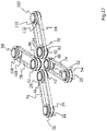
- figure 1 shows a perspective view of a motor-gear unit 210.
- the motor-gear unit 210 has a motor 212 and a gear 214 on.
- the motor-gear unit 210 is spring elements 216 with an in figure 34 bogie not shown connected.
- the motor-gear unit 210 drives a wheelset shaft 218 .
- the transmission 214 of the motor-transmission unit 210 is coupled to the wheelset shaft 218 via a clutch device 220 .
- the coupling device 220 has a (first) flange 222 and a connecting device VE.
- the connecting device VE has a (second) flange 224 .
- the flange 222 is coupled to a transmission output shaft 226 of the transmission 214 via a toothing 228 .
- the flange 224 is coupled to the wheelset axle 218 .
- the wheel set axle 218 has a projection 230 in the form of a circumferential section with a larger outer diameter. The flange 224 can be pressed onto the projection 230 .
- the flange 222 and the flange 224 are connected to each other by a thread-reinforced hinge device 232 .
- the thread-reinforced joint device 232 is composed of a plurality of coupling bodies 234 .
- the coupling bodies 234 each have an elastic body in which a bundle of threads (not shown) and a support device for the bundle of threads can be embedded.
- the coupling bodies 234 are screwed to the flange 222 and the flange 224 via screws 236 .
- One screw 236 in each case fixes two coupling bodies 234 that abut one another in sections in the axial direction on the corresponding flange arm 238 or 240 .
- the flanges 222 and 224 have flange arms 238 and 240 .
- the coupling bodies 234 are arranged on the flange arms 238 and 240 in two planes E1 and E2 and are fastened to the flange arms 238 and 240 via the screws 236 .
- Flange arms 238 of flange 222 encircle flange 224 for mating with thread reinforced hinge assembly 232 .
- FIG 2 shows a top view of the motor-gear unit 210 with the coupling device 220.
- the coupling device 220 has the (first) flange 222 and the (second) flange 224, which are connected to one another via the thread-reinforced joint device 232.
- the flange 222 has flange arms 238 which extend at an angle toward the thread reinforced hinge device 232 .
- the flange arms 240 of the flange 224 which extend in the radial direction, can be seen between two adjacent flange arms 238 of the flange 222.
- the flanged arms 238 and 240 are connected to the thread reinforced linkage by bolts 236 .
- the flange 222 is connected to the transmission output shaft 226 of the transmission 2214 via teeth 228 .
- figure 3 shows a front view of the motor-gear unit 210 with the clutch device 220.
- figure 4 shows a sectional view along the line IV-IV in FIG figure 3 , which shows the course of section line IV-IV through motor-gear unit 210.
- the coupling device 220 has the flange 222 and the flange 224 .
- Flange 222 includes flange arms 238 and a mounting portion 242 that is annular. At the end of this attachment portion 242 is in the Figures 34 and 35 toothing 228 shown is formed.
- the fastening section 242 has openings 244 via which the flange 222 can be screwed to the transmission output shaft 226 .
- the transmission output shaft 226 also has openings 246 .
- Bolts 248 may be inserted into openings 244 and 246 to connect flange 222 and transmission output shaft 226 together.
- the flange arms 238 initially extend radially outwards before merging into a section 250 extending in the axial direction.
- the flange arms 238 thus extend at an angle in the direction of the thread-reinforced joint device 232.
- an opening 252 is formed which has an internal thread.
- the screws 236 for fastening the thread-reinforced joint device 232 to the flange 222 can be screwed into the internal thread.
- the opening 252 is designed as a through opening.
- Fastening surfaces 254 are formed on the section 250 extending in the axial direction, on which the thread-reinforced joint device 232 can be supported.
- a recess 256 is formed on the fastening surfaces 254, in which a bushing 258 of the thread-reinforced joint device can be accommodated at least in sections.
- the bushings 258 extend through the coupling bodies 234 and connect two coupling bodies 234 to one another. The end face of the bushing 258 can be supported axially on the bottom of the recess 256 .
- the flange arms 238 surround the flange 224, ie the flange arms 238 engage with their axial section 250 between the flange arms 240 of the flange 224, which extend in the radial direction.
- Flange 224 includes flange arms 240 and attachment portion 260 .
- the attachment section 260 is tubular and can be pressed onto the attachment projection 230 of the wheel set axle 218 .
- the axial extent of the tubular attachment portion 260 corresponds to the axial extent of the attachment projection 230.
- the tubular attachment portion 260 extends through the central opening O of the thread-reinforced joint device 232. Starting from the tubular attachment portion 260, the flange arms 240 extend radially outwards.
- the Flange arms 240 are formed with mounting surfaces 262 each having an opening 264 .
- the opening 264 may be internally threaded.
- a screw 236 can be screwed to the internal threads in the opening 264 to establish a connection between the thread-reinforced hinge device 232 and the flange 224 .
- the fastening surface 262 has a projection 266 in the region of the opening 264 .
- a recess is formed on the projection 266, in which a bushing 258 can be accommodated at least in sections. The end face of the bushing 258 can be supported on the bottom of the recess.
- the attachment portion 260 of the flange 224 and the attachment portion 242 of the flange 222 are offset from one another in the axial direction. This results in a predetermined axial distance A between the fastening section 242 of the flange 222 and the flange 224 . Due to the angled design of the flange arms 238 of the flange 222 with their sections 250 extending in the axial direction, the fastening surfaces 254 of the flange 222 and the fastening surfaces 262 of the flange 224 lie in one plane when the coupling device 220 is at rest. The flange 222 can thus encompass or span over the flange 224 .
- the flange arms 238 and 240 of the flanges 222 and 224 are located on the same axial side of the thread reinforced hinge device 232 .
- the co-planar mounting surfaces 254 and 262 of the flange arms 238 and 240 accordingly face the thread reinforced linkage 232 on the same axial side.
- the thread-reinforced hinge device 232 is held to the mounting surfaces 254 and 262 of the flanges 222 and 224 by a clamping force exerted by the screws 236 with their screw heads.
- the figures 4 and 5 show a variant of the coupling device 220 according to the first embodiment.
- a thread-reinforced joint device 232 which is composed of several coupling bodies (coupling straps) 234
- the coupling device 220 according to FIG Figures 38 and 39 a thread-reinforced joint device 232 in the form of a strap ring (flexible disk) is provided.
- the strap ring is designed in one piece and is screwed to the flanges 222 and 224 via the screws 236 .
- FIG 6 shows a perspective view of a coupling device 2120 according to a second embodiment of the invention.
- the coupling device 2120 has a (first) flange 222 and a (second) flange 224 .
- the flange 222 has an attachment portion 242 and flange arms 238 .
- the toothing 228 is formed on the end face of the fastening section 242 .
- the flange arms 238 have a (first) mounting surface 254 and a (second) mounting surface 268 formed on the axial sides of the flange arms 238.
- the flange 224 has an attachment portion 260 and the flange arms 240 .
- the flanged arms 240 have a (first) mounting surface 262 and a (second) mounting surface 270 formed on opposite axial sides of the flanged arms 240 .
- the flange arms 238 and 240 in this embodiment interlock.
- the thread reinforced hinge device 232 is provided on the mounting surfaces 254, 268 and 262, 270 of the flange arms 238 and 240.
- the thread-reinforced joint device 232 also has joint bodies 272, which are screwed to the fastening surfaces 268 and 270 of the flange arms 238 and 240 via the screws 274.
- the coupling bodies 234 are screwed to the fastening surfaces 254 and 262 of the flange arms via the screws 236 .
- FIG 7 shows a plan view of the coupling device 2120.
- Flange 222 is shown having an attachment portion 242 .
- the end face of the fastening section 242 is provided with teeth 228 .
- the flange arms 238 of the flange 222 are screwed to the coupling bodies 272 via the screws 274 .
- figure 8 shows a sectional view along the line IX-IX in figure 7 .
- figure 8 1 shows how the flange arms 238 and 240 of the flanges 222 and 224 engage one another.
- Flange arms 238 and 240 interlock so that they lie in one plane.
- the thread-reinforced joint device 232 with its coupling bodies 234 and 272 is arranged on the axial sides of the flange arms 238 and 240 .
- the flange arms 238 have a through opening 252 with an internal thread.
- the screws 236 and 274 are screwed into the opening 252 in order to be able to attach the coupling bodies 272 and 234 to the flange arm 238 .
- the opening 252 thus accommodates the two screws 236 and 274 in sections.
- the mounting surfaces 254 and 268 of the flange arms 238 are provided with a recess in which a bushing 258 of the thread-reinforced joint device 232 can be accommodated in sections.
- the bushing 258 can be supported axially on the fastening surfaces 254 and 268 with its end face.
- the flange arms are designed essentially identically to the flange arms 238 .
- the flange arms 240 also have a through opening 264 with an internal thread.
- the screws 270 and 236 are screwed into the opening 264, in order to be able to hold the coupling bodies 234 and 272 on the fastening surfaces 262 and 270 via a clamping force.
- Two coupling bodies 234 and 272 are held on the flange arm 238, 240 by the corresponding screw 236 or 274.
- the coupling bodies 234 are arranged in two planes E1 and E2 on the flange arms 238 and 240 and are fastened to the fastening surfaces 254 and 262 of the flange arms 238 and 240 via the screws 236 .
- the coupling bodies 272 are arranged in two planes E3 and E4 on the fastening surfaces 268 and 272 of the flange arms 238 and 40 and are fastened to the flange arms 238 and 240 via the screws 274 .
- Flange arms 238 and 240 extend axially between planes E1, E2 and E3, E4.
- FIGS. 9 to 12 12 show views of a coupling device 2220 according to a third embodiment, which is relatively similar to the second embodiment.
- the coupling device 2220 has a (first) flange 222 and a (second) flange 224, which in turn have flange arms 238,240.
- Each flange arm 238,240 is connected to the adjacent flange arm 238,240 by a coupling body 234,272.
- Each coupling body 234 is bolted to adjacent flange arms 238 and 240 via bolts 236 and rests against the adjacent flange arms 238,240. The same applies to the coupling bodies 272 and the screws 274.
- the coupling bodies 234 and the coupling bodies 272 are each arranged on the flange arms 238, 240 in a plane E1, E2 and offset from one another in the circumferential direction.
- the thread-reinforced joint device 232 has a plane E1 with coupling bodies 234 on one axial side of the flange arms 238, 240 and a plane E2 with coupling bodies 272 on the opposite axial side of the flange arms 238 and 240.
- Each flange arm 238, 240 is connected via a respective screw 236, 274 to coupling bodies 234, 272 which are offset relative to one another in the circumferential direction.
- Each flange arm 238 and 240 thus has two openings 252 and 264 into which the screws 236 and 274 can be screwed in the axial direction towards one another, i.e. the screws 236 and 274 are inserted on opposite axial sides of the flange arms 238, 240 into the flange arms 238 , 240 screwed.
- the motor-gear unit 210 has a motor 212 and a gear 214.
- the wheel set 276 has a wheel set shaft 218 and two wheels 278 and 280 .
- the motor-gear unit 210 is spring elements 216 with a Bogie (not shown) connected.
- the spring elements 216 are attached to a bearing portion 282 that is connected to the transmission 214 .
- the spring elements 216 are arranged in the direction of the wheelset shaft 218 in a middle or central area of the motor-gear unit 210 .
- Motor-gear unit 210 is coupled to wheel set 276 via a coupling device 320 according to a fourth specific embodiment.
- Motor-gear unit 210 drives wheel 278 of wheel set 276 via clutch device 320 .
- the coupling device 320 has a flange 222 and a connecting device VE, which includes a plurality of connecting elements 284 .
- the connecting elements 284 connect the thread-reinforced joint device 232 to the wheel 278.
- the connecting elements 284 lie against the wheel 278 and the thread-reinforced joint device 232 for this purpose.
- the connecting device VE also has counter-contact elements 286, which rest against the side of the coupling body 234 of the thread-reinforced joint device 232 opposite the connecting elements 284.
- the coupling bodies 234 of the thread-reinforced joint device 232 and the connecting device VE are screwed to the wheel 278 .
- Gear 214 drives thread reinforced linkage 232 via flange 222 .
- the thread-reinforced joint device 232 transmits the drive torque via the connecting elements 284 directly to the wheel 278 of the wheel set 276.
- the drive torque is also transmitted to the wheel 280 via the wheel set shaft 218.
- figure 14 shows a further perspective view of the motor-gear unit 210 and the wheel set 276.
- Spring elements 216 are also provided on a bearing section 288 on the motor 212.
- FIG. The spring elements 216 are used to mount the motor-gear unit 210 on a bogie (not shown).
- figure 15 shows a plan view of the motor-gear unit 210 and the wheel set 276.
- the gear 214 of the motor-gear unit 210 is connected to the wheel set 276 via the clutch device 320.
- the coupling device 320 is bolted to the wheel 278 of the wheel set 276 .
- the transmission 214 is coupled to the clutch device 320 via a flange 222 such that a drive torque can be transmitted from the transmission 214 to the wheel 276 via the clutch device 320 .
- the spring elements 216 are also shown, which are used to support the motor-gear unit 210 on a bogie (not shown).
- the spring elements 216 are arranged in the direction of the wheelset shaft 218 in a middle or central area of the engine-transmission unit 210 .
- the embodiments of the coupling device 220, 2120, 2220, 320 described above have a predetermined radial stiffness.
- the coupling device 220, 2120, 2220, 320 can thus absorb forces acting in the radial direction.
- the coupling device 220, 2120, 220, 320 can also absorb forces, axial forces and bending moments resulting from a drive torque of the vehicle.
- the embodiments of the coupling device 220, 2120, 2220, 320 described above can compensate for relative movements between the motor-gear unit 210 and a wheel set of a vehicle. The compensation of relative movements takes place exclusively under an elastic deformation of the thread-reinforced joint device 232 .
- figure 16 12 shows a perspective view of a thread-reinforced bearing element, generally designated 10, according to a first embodiment.
- the thread-reinforced bearing element 10 can be used to support a motor-gear unit (in figure 16 not shown) on a bogie (not shown).
- the bearing element 10 has an elastic body 12 in which three fastening openings 14, 16 and 18 are formed. Bushings 20 and 22 are received in mounting apertures 14 and 18 .
- the socket accommodated in the fastening opening 16 is in figure 16 not shown or recognizable that it is covered by a spacer 24.
- the spacer 24 extends from the elastic body 12 away. In the figure 16 The end face of the spacer 24 shown lies in a plane with the end faces of the bushings 20 and 22.
- the fastening openings 14, 16, 18 extend in figure 16 thread bundles not shown.
- the bundles of threads loop around the bushings 20, 22 and also the bushing (not shown) arranged in the fastening opening 16.
- the bushing 22 is looped around by two bundles of threads which, starting from the bushing 22 in the elastic body 12, extend in the direction of the fastening openings 16, 18.
- a bundle of threads wraps around the bushing 20 in the fastening opening 18 and the other bundle of threads wraps around the in figure 16 socket, not shown, in the fastening opening 16. Since the bundles of threads, starting from the socket 22,
- the elastic body 12 has a step 26 if it extends offset in the axial direction of the bushings 20, 22 in the direction of the fastening openings 14, 16.
- the step 26 is formed in the elastic body 12 by the axial offset of the two bundles of threads, not shown, of the bearing element 10 . Due to the stage 26, the spacer 24 is provided. The end faces of the sockets 20, 22 and the spacer 24 lie in one plane. This forms a common attachment plane for the bushings 20, 22 and the spacer 24, so that the bushings 20, 22 and the spacer 24 can rest in a common attachment plane on the units to be connected via the bearing element, for example a rail vehicle drive.
- figure 17 shows a plan view of the bearing element 10.
- the bearing element 10 or the elastic body 12 of the bearing element 10 is formed essentially in the shape of a triangle.
- the bushing 20 and the spacer 24 or the fastening openings 16, 18 are arranged in the elastic body 12 offset by a predetermined angle ⁇ relative to one another about the central axis M 22 of the bushing 22 .
- the angle ⁇ is plotted between two imaginary lines L 1 and L 2 .
- the line L 1 extends between the central axis M 22 of the bushing 22 and the central axis M 24 of the spacer 24.
- the line L 2 extends between the central axis M 22 of the bushing 22 and the central axis M 20 of the bushing 20.
- the fastening openings 14 and 16 are about an in figure 17 not shown thread package connected to each other, which wraps around the bushing 22 in the mounting opening 14 and the bushing (not shown) in the mounting opening 16.
- the attachment openings 14 and 18 are also via an in figure 17 not shown thread bundle connected to each other, which wraps around the sockets 20 and 22.
- the thread-reinforced bearing element 10 is designed in such a way that it can provide different rigidities in the x-direction, y-direction and in the z-direction.
- the different rigidities can be used to determine how in which direction and to what extent relative movements of a motor-gear unit (not shown) and/or a wheel set (not shown) can be permitted and compensated for by the bearing element 10 relative to the bogie.
- the thread-reinforced bearing element 10 can have a high level of rigidity, for example, since the two thread bundles are subjected to tensile loads in the z-direction.
- the thread-reinforced bearing element 10 can, for example, be less stiff than in the z-direction, since the two thread bundles are only slightly subjected to tensile loads in the ⁇ -direction.
- the thread-reinforced bearing element 10 can have a relatively low stiffness in order to withstand relatively large deflections of the wheelset and/or the Allow motor-gear unit relative to the bogie in the x-direction or record.
- the x-direction can correspond to the longitudinal direction or the direction of travel of a rail vehicle (not shown).
- the ⁇ direction can correspond to the transverse direction of the rail vehicle and the z direction can correspond to the vertical axis of the rail vehicle.
- thread bundles of the thread-reinforced bearing element 10 thus extend at a predetermined angle ⁇ between the mounting holes 14, 16 and 18 in the elastic body 12 or between the bushings 20, 22 and the bushing covered by the spacer 24 in the mounting hole 16.
- step 26 which indicates the offset of the thread bundles in the axial direction of the bushings 20, 22 and the angular offset (angle ⁇ ′) between the fastening openings 14, 16 and 18 connected via the thread bundles.
- the bundles of threads overlap in particular in the area in which they loop around the bushing 22 .
- the thread bundles extend at the angle ⁇ in the direction of the fastening openings 16 and 18.
- the rigidity of the thread-reinforced bearing element 10 in the x-direction, ⁇ -direction and z-direction can be adjusted via the predetermined angle ⁇ between the two thread bundles. At least the rigidity in the x-direction and ⁇ -direction can be adjusted via the angle ⁇ between the bundles of threads.
- the angle ⁇ can correspond to the angle ⁇ '.
- FIG 18 shows a sectional view along the line III-III in figure 17 .
- the bushings 22 and 28 are embedded at least in sections in the fastening openings 14 and 16 in the elastic body 12 .
- collar elements 30, 32 and 34 are provided on the socket 22 .
- the collar elements 30 and 34 are arranged at the axial ends of the bushing 22 and pressed onto the bushing 22 .
- the collar elements 30 and 34 have a tubular section 36 extending in the axial direction and a section 38 extending in the radial direction.
- the collar elements 30 and 32 are designed as L-shaped collars in cross section.
- the tubular sections 36 point in the direction of the axial ends of the bushing 22, respectively.
- the collar member 32 extends from the outer peripheral surface of the bushing 22 in the radial direction.
- the bundle of threads guided between the collar elements 32 and 34 extends in the elastic body 12 in the direction of the bushing 28 on which the spacer 24 is arranged.
- two collar elements 40 and 42 which are designed in the form of L-shaped collars.
- the collar elements 40 and 42 also have an axial, tubular section 44 and a section 46 extending in the radial direction.
- the collar members 40 and 42 are provided at the axial end portions of the bushing 28 .
- the spacer 24 is provided with a circumferential recess 48 in which an axial end portion of the bushing 28 is received. An end face of the bushing 28 bears against an axial face of the recess 48 .
- the bushing 28 and the spacer 24 are arranged coaxially so that the openings in the bushing 28 and the spacer 24 form a continuous opening.
- the coaxial arrangement of the bushing 28 and the spacer 24 is illustrated by the common central axis M 24/28 .
- the spacer 24 has a reduced outside diameter.
- the spacer 24 is intended to bridge a distance D between the end face, for example, of the bushing 22 and the end face of the bushing 28 in order to have a common fastening plane for all bushings 20 (see FIG figure 17 ), 22 and 28 set up.
- the distance D results from the axial offset between the bundles of threads. This axial offset is also indicated by the step 26 on the elastic body 12 .
- the end face of the spacer 24 lies with the end faces of the bushings 20 and 22 in one plane. In this way, the attachment of the bearing element 10 to the units to be stored via the bearing element 10 should be simplified.
- FIG 19 shows a sectional view along the line IV-IV in FIG figure 18 .
- bushings 20 and 28 are shown.
- the spacer 24 is arranged, over which a distance in the axial direction of the sockets between the end face of the bushing 20 and the end face of the bushing 28 is to be bridged, so that the end faces of the spacer 24 and the bushing 20 lie in one plane.
- the bushings 20 and 28 and thus also the thread packages wrapped around the bushings 20 and 28 are offset from one another in the axial direction. This axial offset results from the axial offset that is given to the bundles of threads when the collar elements 30 , 32 and 34 wrap around the bushing 22 .
- the elastic body 12 also has a step 60 on its axial end side opposite to the end side with the step 26 .
- Collar elements 52 and 54 are arranged on the bushing 20 and are located at the axial end portions of the bushing 20 .
- the collar elements 52 and 54 have a section 56 extending in the axial direction and a section 58 extending in the radial direction.
- the collar elements 52 and 54 like the collar elements 30, 34, 40 and 42, are therefore designed as collars with an L-shaped cross section.
- the collar elements 40, 42 on the bushing 28 serve to guide one of the thread bundles of the bearing element 10.
- the collar elements 52 and 54 on the bushing 20 serve to guide the respective other thread packet (not shown) of the bearing element 10.
- figure 20 12 shows a perspective view of an elastic joint body 100 according to a second embodiment.
- the thread-reinforced bearing member 100 has six attachment holes 14, 16, 18, 62, 64 and 66 formed in the elastic body 12. As shown in FIG. A bushing 20, 22, 28, 68, 70 and 72 is received in each mounting aperture 14, 16, 18, 62, 64 and 66.
- figure 21 12 shows a plan view of the thread-reinforced bearing element 100.
- the bearing element 100 has six attachment openings 14, 16, 18, 62, 64 and 66 in which a bushing 20, 22, 28, 68, 70 and 72 is received, respectively.
- the bushings 20 and 28 are each connected to the bushing 22 via a bundle of threads.
- the bushings 70 and 72 are also connected to the bushing 68 via a bundle of threads (not shown).
- the thread bundles extend in the elastic body 12.
- the thread bundles extend at an angle of ⁇ 1 and ⁇ 2 to each other in the elastic body 12.
- the bushings 20, 28 and 70, 72 are at a predetermined angle ⁇ 1 ' and ⁇ , respectively 2 ' about the central axes M 22 and M 68 of the bushings 22 and 68 in an offset manner.
- the angles ⁇ 1 , ⁇ 2 can correspond to the angles ⁇ 1 'and ⁇ 2 '.
- the sockets 22 and 68 are looped around by two sets of threads. The bundles of threads also extend, starting from the bushings 22 and 68 and offset from one another by a predetermined angle, in the direction of the respective bushing 20, 28, 70 and 72.
- the angles ⁇ 1 , ⁇ 2 and ⁇ 1 'and ⁇ 2 ' are between the Lines L 1 , L 2 and L 3 , L 4 plotted.
- Line L 1 extends between central axis M 22 of bushing 22 and central axis M 28 of spacer 28.
- Line L 2 extends between central axis M 22 of bushing 22 and central axis M 20 of bushing 20.
- Line L 3 extends between central axis M 70 of bushing 70 and central axis M 68 of bushing 68.
- Line L 4 extends between central axis M 72 of bushing 72 and central axis M 68 of bushing 68.
- the structure of the bearing element 100 corresponds to the structure of the bearing element 10 according to the embodiments described above with regard to the arrangement of the three bushings 20, 22, 28 or 68, 70, 72 coupled via bundles of threads and their connection via bundles of threads.
- the bearing element 100 contains in its elastic body 12 two separate arrangements of three bushings 20, 22, 28 and 68, 70, 72, which are each connected via two bundles of threads (not shown).
- Each of these arrangements of three bushings 20, 22, 28 or 68, 70, 72 connected via thread bundles corresponds to the arrangement of the thread bundles and the bushings 20, 22, 28 according to the first embodiment, with reference to FIG Figures 1 to 4 was described.
- the two arrangements of three bushings 20, 22, 28 or 68, 70, 72 connected via bundles of threads are connected to one another exclusively via the elastic body 12.
- figure 22 shows a sectional view along the line VII-VII in figure 21 .
- the bushing 22 is connected to the bushing 20 via a bundle of threads 74 .
- the bundle of threads 74 loops around the bushings 20 and 22.
- the collar elements 52 and 54 are arranged on the bushing 20 and guide the bundle of threads 74 on the bushing and support it axially.
- the bushing 22 is wrapped around by another bundle of threads 76, which extends in the direction of the bushing 28 (see figure 21 ) extends.
- the bundles of threads 74 and 76 are held on the bushing 22 via the collar elements 30 and 34 and guided axially.
- the bushing 70 is wrapped around by a bundle of threads 78 which is held on the bushing 70 by collar elements 80 and 82 .
- the collar elements 80 and 82 are in the form of L-shaped collars.
- FIG 23 shows a perspective view of a main body of the thread-reinforced bearing element 100, without the elastic body 12.
- the sockets 20, 22, 28, 68, 70 and 72 are shown, which are connected to one another in pairs via the thread packages 74, 76, 78 and 84.
- the bushings 20 and 22 are connected to one another via the bundle of threads 76 .
- the bushings 22 and 28 are connected to one another by the thread package 74 .
- Bushings 68 and 70 are connected via filament pack 78 and bushings 68 and 72 are connected via filament pack 84 .
- the sockets 22 and 68 each of two thread packages 74, 76 and 78, 84 looped.
- the thread bundles 74, 76 and 78, 84 overlap in the area of the bushings 22 and 68 and, starting from the bushings 22 and 68, each extend in the direction of the other bushings 20, 28, 70 and 72 assigned to them.
- the thread packages 74, 76 and 78, 84 are secured to the sockets 20, 22, 28, 68, 70 and 72 via collars 30, 40, 42, 52, 54, 82, 86, 88 and 90 which are L-shaped in cross section.
- Two collar elements 30, 40, 42, 52, 54, 82, 86, 88 and 90 are assigned to each thread bundle 74, 76 and 78, 84, even if in particular figure 8 partially only one collar element assigned to the respective thread bundle 74, 76 and 78, 84 is shown.
- figure 24 shows a top view of a base body of the thread-reinforced bearing element 100.
- the bushings 20 and 28 are offset by a predetermined angle ⁇ 1 about the central axis M 22 of the bushing 22.
- the angle ⁇ 1 is plotted between the imaginary lines L 1 and L 2 which intersect in the central axis M 22 of the bushing 22 .
- the bushings 70 and 72 are also offset by a predetermined angle ⁇ 2 about the central axis M 68 of the bushing 68 .
- the angle ⁇ 2 is removed between the imaginary lines L 3 and L 4 which intersect the central axis M 68 of the bushing 68 .
- the thread package 74 (first thread package) and the thread package 76 (second thread package) overlap in the area of the bushing 22 and, starting from the bushing 22, extend in the direction of the bushing 20 (thread package 74) and the bushing 28 (thread package 76).
- Thread pack 78 (third thread pack) and thread pack 84 (fourth thread pack) also overlap in the area at bushing 68 and then extend in the direction of bushing 70 (thread pack 78) and bushing 72 (thread pack 84).
- the thread bundles 74, 76, 78, 84 have parallel strands in the area between the bushings 20, 22, 28, 68, 70 and 72.
- the parallel strands of the thread packages 74, 76, 78, 84 run at a predetermined angle to one another in order to be able to couple the individual bushings 20, 22, 28, 68, 70 and 72 to one another in pairs in a manner that transmits tensile forces.
- figure 25 shows a side view of the main body of the thread-reinforced bearing element 100.
- the thread bundles 74, 76 can be seen which connect the sockets 20, 22 and 28 to one another.
- the suture packages 74 and 76 are secured to the bushing 22 by the collar members 30 and 34 .
- the collar members 40 and 42 hold the suture package 74 to the bushing 28.
- the suture package 76 is supported by the collar members 52 and 54 held on the socket 20.
- the collar elements 86 and 88 hold the thread packets 78 and 84 on the bushing 68.
- the thread packet 78 is held on the bushing 70 via the collar elements 82 and 92.
- the collar element 90 and a further collar element are provided on the socket 72 in order to secure the thread package 84 on this socket.
- figure 26 12 shows a perspective view of a thread-reinforced bearing element 200.
- the elastic body 12 of the bearing element is essentially X-shaped and has eight fastening openings 14, 16, 18, 62, 64, 66, 94 and 96.
- a bushing 20, 22, 28, 68, 70, 72, 98 and 102 is received in each of the mounting apertures 14, 16, 18, 62, 64, 66, 94 and 96.
- the mounting holes 14, 22, 94 and 96 and the bushings 20, 22, 98 and 102 received therein are located at the outer ends of the legs of the X-shape of the bearing member 200.
- the mounting holes 18, 62, 64 and 66 are with the their associated bushings 28, 68, 70 and 72 in the central portion of the X-shape, ie in the intersection of the legs of the X-shape.
- figure 27 shows a perspective view of the base body of the bearing element 200.
- the bearing element 200 has four bundles of threads 74, 76, 78 and 84, each of which connects two bushings 20, 22, 28, 68, 70, 72, 98 and 102 to one another.
- Thread packet 74 connects or wraps around bushings 20 and 68.
- Thread packet 76 connects bushings 22 and 28.
- Thread packet 78 connects bushings 72 and 98.
- Thread packet 84 wraps around bushings 70 and 102.
- Thread packets 74, 76, 78 and 84 are attached via collar members 30, 34, 40, 42, 52, 54, 82, 86, 88, 90, 92, 104, 106, 108, 110 and 112 to bushings 20, 22, 28, 68, 70, 72 , 98 and 102 held.
- the collar elements 30, 34, 40, 42, 52, 54, 82, 86, 88, 90, 92, 104, 106, 108, 110 and 112 are formed in cross-section in the form of L-shaped collars.
- the thread bundles 74, 76, 78 and 84 are essentially of the same length and have the same cross-section.
- figure 28 shows a top view of the bearing element 200.
- the X-shape of the elastic body 12 of the bearing element 200 becomes clear.
- the bushings 20, 22, 98 and 102 are arranged at the outer ends of the legs of the X-shape of the elastic body 12.
- FIG. The thread bundles 74, 76, 78 and 84 in the elastic body 12 extend from the bushings 20, 22, 98 and 102 in the direction of the respective other bushing 28, 68, 70 and 72, which is located in a central region of the elastic body 12 of the Bearing element 200 are arranged.
- the symmetry axis SE is drawn.
- the thread-reinforced bearing element 200 is axisymmetric or constructed mirror-symmetrically.
- the bundles of threads 74 and 76 extend at an angle ⁇ 1 to one another in the elastic body 12, as a result of which the distance between the bundles of threads 74 and 76 increases along the axis of symmetry SE.
- the bundles of threads 78 and 84 extend at an angle ⁇ 2 to one another in the elastic body 12. Here, too, the distance along the axis of symmetry SE increases.
- figure 29 shows a sectional view along the line XIV-XIV in figure 28 .
- the bushing 22 is wrapped around by the bundle of threads 76 .
- the bundle of threads 76 is supported axially on the bushing 22 via the collar elements 30, 34, which are L-shaped in cross section.
- the bushing 98 is wrapped around by the thread package 78 which is held by the collar elements 106 and 108 on the bushing 98 .
- the Figures 30 and 31 show a thread-reinforced bearing element 300.
- the elastic body 12 of the bearing element 300 is essentially X-shaped.
- the structure of the bearing member 300 according to this embodiment largely corresponds to the structure of the bearing member 200 described above.
- the thread-reinforced bearing element 300 is also constructed axially symmetrically, as can be seen from the axis of symmetry SE.
- the bundles of threads 74 and 76 extend at an angle ⁇ 1 to one another in the elastic body 12, as a result of which the distance between the bundles of threads 74 and 76 increases along the axis of symmetry SE.
- FIG figure 31 shows a sectional view along the line XVI-XVI in FIG figure 30 .
- the bushing 22 is wrapped around by the bundle of threads 76 .
- the bundle of threads 76 is supported axially on the bushing 22 via the collar elements 30, 34, which are L-shaped in cross section.
- the bushing 98 is wrapped around by the thread package 78 which is held by the collar elements 106 and 108 on the bushing 98 .
- figure 32 12 shows a perspective view of a thread-reinforced bearing element 400.
- the elastic body 12 of the bearing element 400 is essentially Y-shaped and has five fastening openings 14, 16, 18, 62 and 64.
- FIG. In each of the mounting holes 14, 16, 18, 62 and 64 is a bushing 20, 22, 28, 68, 70 added.
- the bushings 20, 22, 28 or the fastening openings 14, 16, 18 with the said bushings are essentially arranged in one line. Starting from the bushing 28, the two legs of the Y-shape extend in the direction of the bushings 68 and 70.
- Figure 33 shows a perspective view of the main body of the thread-reinforced bearing element 400.
- the bushings 20 and 22 are wrapped by the thread bundle 74.
- the bundle of filaments 74 is retained on the bushings 20 and 22 by the collar members 30, 34, 52 and 54.
- the sockets 28, 68 and 70 are connected to one another via the bundles of threads 76 and 78.
- the thread bundles 76, 78 loop around the bushing 28 and, starting from the bushing 28, extend in the direction of the bushings 68 and 70.
- the thread bundle 76 loops around the bushings 28 and 68.
- the thread bundle 78 loops around the bushings 28 and 70.
- the thread bundles 76 and 78 are provided offset in the axial direction on the bushing 28 .
- the thread bundle 74 has a larger cross section than the thread bundles 76 and 78.
- the cross section of the thread bundle 74 in the axial direction of the bushings essentially corresponds to the cross section
- figure 34 12 shows a top view of the thread-reinforced bearing element 400.
- the bearing element 400 is essentially Y-shaped.
- the thread packet 74 extends in the elastic body 12 between the bushings 20 and 22. Starting from the bushing 28, the thread packets 76 and 78 extend in the elastic body 12 in the direction of the bushings 68 and 70, respectively.
- the axes M 20 , M 22 and M 28 lie on an imaginary line L 1 which corresponds to the axis of symmetry SE of the thread-reinforced bearing element 400 .
- the bearing element 400 is thus constructed with mirror symmetry.
- An imaginary line L 2 extends between the sockets 70 and 28 .
- a further imaginary line L 3 extends between the sockets 68 and 28 .
- Lines L 1 , L 2 and L 3 intersect at central axis M 28 of bushing 28.
- Lines L 2 and L 3 extend at a predetermined angle ⁇ to one another.
- the bushings 68 and 70 with their central axes M 68 and M 70 are arranged offset from one another by the predetermined angle ⁇ ′ about the central axis M 28 of the bushing 28 .
- the bundles of threads 76 and 78 extend at an angle ⁇ to one another in the elastic body. The angle ⁇ corresponds to the angle ⁇ '.
- figure 35 shows a sectional view along the line XX-XX in figure 34 .
- the bundle of threads 74 is held on the bushing 20 via the collar elements 52 and 54 and on the bushing 22 via the collar elements 30 and 34 .
- the thread bundle 74 has a larger cross section than the thread bundles 76 and 78 on.
- the cross section of the thread bundle 74 in the axial direction of the bushings essentially corresponds to the cross sections of the thread bundles 76 and 78 together.
- the thread package 78 extends in the direction of the bushing 70.
- the thread package 78 loops around the bushings 28 and 70.
- the thread package 78 is held together with the thread package 76 via the collar elements 40 and 42 on the bushing 28.
- the bundle of threads is held on the bushing 70 via the collar elements 82 and 92 . Since the two bundles of threads 76 and 78 are offset from one another in the axial direction in the direction of the bushings 68 and 70 (see figure 34 ) extend, the elastic body 12 has a step 26, which also in figure 34 is recognizable.
- figure 36 12 shows a perspective view of a thread-reinforced bearing element 500.
- the thread-reinforced bearing element 500 is angled and has an elastic body 12 in which three fastening openings 14, 16 and 18 are formed. Each mounting aperture 14, 16 and 18 receives a bushing 20, 22 and 28, respectively.
- FIG 37 shows a perspective view of the main body of the thread-reinforced bearing element 500.
- the bushings 20, 22 and 28 are connected to one another via the thread bundles 74 and 76.
- the thread bundles 74 and 76 both loop around the bushing 22 and then each extend in the direction of one of the bushings 20 or 28.
- the thread packet 76 is held on the bushing 28 via collar elements 52 and 54 that are L-shaped in cross section.
- the collar elements 30 and 34 secure the two thread bundles 74 and 76 on the socket 22.
- the thread bundle 74 is held on the socket 20 via the collar elements 40 and 42.
- FIG 38 shows a top view of the thread-reinforced bearing element 500.
- the thread bundles 74 and 76 extend between the bushings 20, 22 and 28.
- the two thread bundles 74 and 76 wrap around the bushing 22.
- the thread bundle 74 extends from the bushing 22 in the direction of the socket 20 in order to wrap around it.
- the thread package 76 extends in the direction of the bushing 28.
- the central axis M 20 of the bushing 20 and the central axis M 22 of the bushing 22 lie on an imaginary L 1 .
- the central axis M 22 of the bushing 22 and the central axis M 28 of the bushing 28 lie on an imaginary line L 2 .
- Lines L 1 and L 2 intersect at central axis M 22 of bushing 22.
- Lines L 1 and L 2 extend at a predetermined angle ⁇ to each other.
- the bushings 20 and 22 are thus at the predetermined angle ⁇ about the central axis M 22 the socket 22 offset from one another.
- the angle ⁇ essentially corresponds to 125°.
- FIG 39 shows a sectional view of the thread-reinforced bearing element 500 along section line XXIV-XXIV in FIG figure 38 .
- the bundles of threads loop around bushing 22 offset in relation to one another in the axial direction of the bushings.
- the thread bundle 74 extends to the socket 20 and wraps around it.
- the bundle of threads 74 is held on the bushing 20 by the collar elements 52 and 54 .
- the bundle of threads 76 is supported axially on the bushing 28 via the collar elements 40 and 42 .
- the bundles of threads 74 and 76 are offset from one another in the axial direction of the bushings. This axial offset of the bundles of threads 74 and 76 is evident from the steps 26 and 60 on the elastic body 12 .
- the axial offset essentially corresponds to the axial extent of a thread bundle 74 or 76 in the axial direction.
- figure 40 12 shows a perspective view of a thread-reinforced bearing element 600.
- the elastic body 12 of the bearing element is plate-shaped and rectangular and has eight fastening openings 14, 16, 18, 62, 64, 66, 94 and 96.
- a bushing 20, 22, 28, 68, 70, 72, 98 and 102 is received in each of the mounting apertures 14, 16, 18, 62, 64, 66, 94 and 96.
- the mounting holes 14, 22, 94 and 96 and the bushings 20, 22, 98 and 102 received therein are located in a corner of the rectangular elastic body 12 of the bearing member 600, respectively.
- the attachment openings 18, 62, 64 and 66 are located with their associated bushings 28, 68, 70 and 72 in the central area of the elastic body 12.
- figure 41 shows a perspective view of the base body of the bearing element 200.
- the bearing element 200 has four bundles of threads 74, 76, 78 and 84, each of which connects two bushings 20, 22, 28, 68, 70, 72, 98 and 102 to one another.
- Thread pack 74 connects or wraps around bushings 20 and 68.
- Thread pack 76 connects bushings 22 and 28.
- Thread pack 78 connects bushings 72 and 98.
- Thread pack 84 wraps around bushings 70 and 102.
- the pairs of bushings thus formed are interconnected only by the elastic body 12 (see Figure 42 ).
- the thread bundles 74, 76, 78 and 84 are attached to the bushings 20, 22, 28, 68, 70, 72, 98 and 102 held.
- the collar elements 30, 34, 40, 42, 52, 54, 82, 86, 88, 90, 92, 104, 106, 108, 110 and 112 are in cross section in Form of L-shaped collar formed.
- the thread bundles 74, 76, 78 and 84 are essentially of the same length and have the same cross section.
- the thread bundles 74, 76, 78 and 84 are arranged in an X-shape.
- the bundles of threads 74, 76, 78 and 84 thus run at an angle to one another.
- the sockets 28, 68, 70 and 72 are located adjacent to each other. Starting from the bushings 28, 68, 70 and 72, the thread bundles 74, 76, 78 and 84 extend in the direction of the outer bushings 20, 22, 98 and 102.
- Figure 42 shows a plan view of the bearing member 600.
- the thread bundles 74, 76, 78 and 84 extend in an X-shape in the elastic body 12 of the bearing member 600.
- the bushings 20, 22, 98 and 102 are on the outer edge of the elastic body 12 in the corners of the rectangle arranged. From the sockets 20, 22, 98 and 102, the thread packages 74, 76, 70, 78 and 84 in the elastic body 12 extend towards the other socket 28, 68, 70 and 72, which is in a central region of the elastic body 12 of the bearing element 200 are arranged.
- the thread bundles 74, 76, 70, 78 and 84 extend outwards in an X-shape, starting from the bushings 28, 68, 70 and 72 arranged in a central region of the elastic body 12.
- the bundles of threads 74 and 76 extend at an angle ⁇ 1 to one another in the elastic body 12, as a result of which the distance between the bundles of threads 74 and 76 increases along the axis of symmetry SE.
- the bundles of threads 78 and 84 extend at an angle ⁇ 2 to one another in the elastic body 12.
- the thread bundles 74, 76, 78 and 84 loop around the sockets 20, 22, 28, 68, 70, 72, 98 and 102 in pairs to form socket pairs.
- the socket pairs formed are only connected to one another via the elastic body 12 .
- Figure 43 shows a sectional view along the line XXVIII-XXVIII in Figure 42 .
- the bushings 22 and 28 are looped around by the bundle of threads 76 .
- the bundle of threads 76 is supported axially on the bushings 22 and 28 via the collar elements 30, 34, 40 and 42, which are L-shaped in cross section.
- the bushings 72 and 98 are wrapped around by the thread package 78 which is held by the collar elements 90, 104, 106 and 108 on the bushings 72 and 98.
- FIG. 10 shows a perspective view of a section of a bogie 1000 of a rail vehicle.
- the bogie 1000 has two frame elements 102 extending in parallel and a transverse element 104 extending transversely to the two frame elements 102 .
- On bogie 1000 is a wheel set 106 stored.
- the wheel set 106 has two rail vehicle wheels 108 which are connected to one another via a wheel set shaft 110 .
- the wheel set 106 is driven via a motor-gear unit 112 .
- the motor-transmission unit 112 has a motor 114 and a transmission 116 .
- the torque provided by the engine 114 is translated by the transmission 116 and transmitted to the wheelset shaft 110 .
- Bearing points 118 are formed on motor-gear unit 112 .
- Bearing points 120 are formed on the bogie 1000 .
- the bearing points 120 are provided on the transverse element 104 of the bogie 1000 .
- the thread-reinforced bearing elements 10 connect the bearing points 118 on the motor-gear unit 112 to the bearing points 120 on the bogie 1000.
- the thread-reinforced bearing elements 10 are connected to the bearing points 118, 120 via connecting elements. These connecting elements can be screws, for example.
- the motor-transmission unit 112 is supported on the wheelset shaft 110 via the coupling device 122 .
- the coupling 122 includes a thread reinforced hinge 124, a first flange 126 and a second flange 128.
- the thread reinforced hinge device 124 connects the first flange 126 to the second flange 128.
- the thread reinforced hinge device 124 is a flex washer or tab ring.
- the thread-reinforced joint device 124 has at least one elastic body EK, in which one or more thread bundles (not shown) are embedded.
- the clutch device 122 is connected to the transmission output shaft 130 of the transmission 116 with the first flange 126 .
- the clutch 122 is connected to the wheel set shaft 110 with the second flange 128 .
- the clutch 122 has a high radial rigidity. As a result, the clutch 122 can fulfill the function of a bearing for the motor-gear unit 112 .
- the bearing elements 10 have different rigidities in the x-direction, ⁇ -direction and z-direction.
- the bearing elements 10 have a relatively high rigidity in the z-direction, since the thread bundles (not shown) of the bearing elements are loaded in the pulling direction 10 in the z-direction. In the z-direction, the bearing elements 10 support at least part of the weight of the motor-gear unit 112 and are therefore very stiff in the z-direction.
- the bearing elements 10 are somewhat less stiff in the ⁇ direction, since the thread bundles (not shown) in the bearing elements 10 are only partially subjected to tensile stress in the ⁇ direction due to the angle at which they extend to one another.
- At least the rigidity in the ⁇ -direction and in the z-direction can be adjusted by the angle of the bundles of threads relative to one another.
- the bearing elements 10 In X direction the bearing elements 10 have a low rigidity, since the wheel set 106 is deflected in the x-direction during a braking process. When the wheelset 106 deflects, the entire motor-gear unit 112 must follow the deflection of the wheelset 106 , with this effect being reduced by the radial rigidity of the coupling device 122 .
- the bearing elements 10 must therefore be soft in the x-direction in order to allow or compensate for a movement of the motor-gear unit 112 when the wheelset 106 deflects.
- figure 45 10 shows a plan view of the bogie 1000 according to FIG figure 44 .
- figure 45 10 shows a plan view of the bogie 1000 according to FIG figure 44 .
- the two wheel sets 106 are shown on the bogie 1000, which have two wheels 108 and a wheel set shaft 110.
- the motor-transmission unit 112 is supported on the wheelset shaft 110 via the coupling device 122 .
- the motor-gear unit 112 is mounted on the bogie 1000 via the bearing elements 10 .
- Figure 46 shows an enlarged detail of the top view according to FIG figure 45 .
- the motor-gear unit 112 is mounted on the bogie 1000 via the bearings 10 .
- the bearing points 118 are formed on the motor-gear unit 112 .
- the bearing points 120 are also formed on the transverse element 104 of the bogie 1000 .
- the thread-reinforced bearing elements 10 are connected to the bearing points 118, 120 via connecting elements in order to mount the motor-gear unit 112 on the bogie 1000.
- Motor-gear unit 112 is connected to wheel set 106 via clutch device 122 .
- the coupling 122 has a first flange 126 and a second flange 128 which are connected to each other via the thread-reinforced hinge device 124 .
- the first flange 126 is coupled to the transmission output shaft 130 of the transmission 116 via corresponding splines (not shown).
- the second flange 128 is pressed onto the wheelset shaft 110 in order to create a non-rotatable connection with the wheelset shaft 110 .
- FIG 47 shows a perspective view of the motor-gear unit 112, the wheelset shaft 110 and a coupling device 122.
- the coupling device 122 has the thread-reinforced joint device 124.
- thread-reinforced joint device 124 is formed by a strap coupling.
- the thread-reinforced joint device 124 is composed of several thread-reinforced coupling elements 132 .
- the coupling elements 132 provide a connection between the first flange 126 and the second flange 128.
- the first flange 126 and the second flange 128 are arranged on the same axial side of the thread-reinforced hinge device 124.
- FIG. On the motor-gear unit 112, the bearing elements 10 are also arranged.
- the bearing elements 10 are provided with connection elements 134 .
- the connecting elements 134 can be screws and are used to connect the bearing elements 10 to the bogie 1000 (see FIG figure 45 ).
- the connecting means 134 extend in the x-direction
- figure 48 shows a plan view of the motor-gear unit 112, the wheelset shaft 110 and the coupling device 122.
- the coupling device 122 has the first flange 126 and the second flange 128.
- the flange 126 is coupled to a transmission output shaft 130 of the transmission 116 via teeth.
- the flange 128 is coupled to the wheelset axle 110 .
- the flange 126 and the flange 128 are connected to each other by a thread-reinforced hinge device 124 .
- the thread-reinforced joint device 124 is made up of a plurality of coupling elements 132 .
- the coupling elements 132 each have an elastic body EK, in which a bundle of threads (not shown) can be embedded.
- the coupling members 132 are connected to the flange 126 and the flange 128 via fasteners 136 such as bolts.
- One connecting element 136 in each case fixes two coupling elements 132 that abut one another in sections in the axial direction on a corresponding flange arm 138 or 140.
- the connecting elements 134 extend in the axial direction through the thread-reinforced joint device 10 into the flange arms 138, 140.
- the coupling elements 132 are arranged in two planes E1 and E2 on the flange arms 138 and 140 and are fastened to the flange arms 138 and 140 via the connecting elements 136 .
- the flange arms 38 of the flange 126 encircle the flange 128 for coupling to the thread reinforced hinge device 122 can.
- Motor-gear unit 112 is connected to wheelset shaft 110 via clutch 130 .
- Bearing portions 118 are provided on the motor 114 and the transmission 116 .
- the bearing portions 118 are connected to the bearing members 10 via the fasteners 134 such as screws with a hex head.
- the bearing elements 10 are also provided with connecting elements 142, which can also be screws.
- the connecting elements 142 can connect the motor-gear unit 112 to the frame element 104 (see FIG Figures 44 and 45 ) associate.
- the motor-gear unit 112 is connected to the bogie 1000 via the bearing elements 10 and the connecting elements 134 , 142 .
Landscapes
- Engineering & Computer Science (AREA)
- General Engineering & Computer Science (AREA)
- Mechanical Engineering (AREA)
- Rolling Contact Bearings (AREA)
- Measurement Of The Respiration, Hearing Ability, Form, And Blood Characteristics Of Living Organisms (AREA)
- Measuring Pulse, Heart Rate, Blood Pressure Or Blood Flow (AREA)
- Eye Examination Apparatus (AREA)
- Springs (AREA)
Description
Die vorliegende Erfindung betrifft eine Kupplungsvorrichtung für einen Fahrzeugantrieb, insbesondere für den Antrieb eines Schienenfahrzeugs.The present invention relates to a clutch device for a vehicle drive, in particular for the drive of a rail vehicle.
Ein Anwendungsgebiet einer derartigen Kupplungsvorrichtung können beispielsweise Hochflurfahrzeuge sein. Insbesondere Schienenfahrzeuge können in Form von Hochflurfahrzeugen ausgeführt sein. Unter einem Hochflurfahrzeug ist ein Fahrzeug, insbesondere ein Schienenfahrzeug, zu verstehen, bei dem der Boden des Innenraums im Bereich der Oberkante eines Rades oder oberhalb der Oberkante eines Rades des Fahrzeugs angeordnet ist. Der Boden des Innenraums befindet sich dadurch in etwa auf Höhe des Bahnsteigs. Beispielsweise U-Bahnen werden häufig mit Hochflurfahrzeugen betrieben.A field of application of such a coupling device can be, for example, high-floor vehicles. In particular, rail vehicles can be designed in the form of high-floor vehicles. A high-floor vehicle is a vehicle, in particular a rail vehicle, in which the floor of the interior is arranged in the area of the upper edge of a wheel or above the upper edge of a wheel of the vehicle. The floor of the interior is thus approximately at the level of the platform. For example, subways are often operated with high-floor vehicles.
Eine Vielzahl von Schienenfahrzeugen weist eine Motor-Getriebe-Einheit auf, die am Drehgestell oder am Wagenkasten des Schienenfahrzeugs befestigt ist. Der Radsatz ist elastisch am Drehgestell gelagert und mit dem Getriebe der Motor-Getriebe-Einheit gekoppelt. Aufgrund der elastischen Lagerung des Radsatzes am Drehgestell kann es zu Relativbewegungen zwischen dem Drehgestell und dem Radsatz kommen. Bei Schienenfahrzeugen werden diese Relativbewegungen über komplexe Kupplungsvorrichtungen ausgeglichen. Diese komplexen Kupplungsvorrichtungen können beispielsweise in Form einer Keilpaketkupplung ausgebildet sein. Derartige Kupplungsvorrichtungen sind beispielsweise in dem Dokument
Weitere Beispiele für Kupplungsvorrichtungen finden sich in
Es ist eine Aufgabe der vorliegenden Erfindung, eine Kupplungsvorrichtung der eingangs bezeichneten Art bereitzustellen, die wartungsarm und einfach zu montieren ist, und gleichzeitig einen Ausgleich von Relativbewegungen zwischen einer Motor-Getriebe-Einheit und einem Radsatz eines Fahrzeugs ermöglicht. Es ist eine weitere Aufgabe der vorliegenden Erfindung, eine Kupplungsvorrichtung bereitzustellen, die insbesondere für den abtriebseitigen Einsatz in einem Schienenfahrzeug geeignet ist. Diese Aufgaben werden mit einer Kupplungsvorrichtung für einen Antrieb eines Fahrzeugs, insbesondere einen Antrieb eines Schienenfahrzeug, mit den Merkmalen des Patentanspruchs 1 gelöst.It is an object of the present invention to provide a coupling device of the type described at the outset that requires little maintenance and is easy to assemble is, and at the same time allows a compensation of relative movements between a motor-transmission unit and a wheelset of a vehicle. It is a further object of the present invention to provide a clutch device which is particularly suitable for use on the output side in a rail vehicle. These objects are achieved with a coupling device for a drive of a vehicle, in particular a drive of a rail vehicle, with the features of
Weitere Ausführungsformen der Erfindung sind in den abhängigen Ansprüchen angegeben.Further embodiments of the invention are given in the dependent claims.
Die erfindungsgemäße Kupplungsvorrichtung für einen Fahrzeugantrieb, insbesondere für den Antrieb eines Schienenfahrzeugs umfasst
- wenigstens einen Flansch, wobei der wenigstens eine Flansch einen Befestigungsabschnitt aufweist, über den der wenigstens eine Flansch mit einem Getriebe koppelbar ist,
- wenigstens eine Verbindungseinrichtung, wobei die wenigstens eine Verbindungseinrichtung wenigstens einen Befestigungsabschnitt aufweist, über den die wenigstens eine Verbindungseinrichtung mit wenigstens einem abgetriebenen Element koppelbar ist, und
- wenigstens eine fadenverstärkten Gelenkvorrichtung, die den Flansch und die Verbindungseinrichtung miteinander verbindet,
- at least one flange, wherein the at least one flange has a fastening section, via which the at least one flange can be coupled to a transmission,
- at least one connecting device, wherein the at least one connecting device has at least one fastening section, via which the at least one connecting device can be coupled to at least one driven-off element, and
- at least one thread-reinforced hinge device which connects the flange and the connecting device to one another,
Die erfindungsgemäße Kupplungsvorrichtung weist eine vorbestimmte radiale Steifigkeit auf. Dadurch kann die erfindungsgemäße Kupplungsvorrichtung in radialer Richtung wirkende Kräfte aufnehmen. Beispielsweise kann die erfindungsgemäße Kupplungsvorrichtung aufgrund ihrer vorbestimmten radialen Steifigkeit einen Teil der Gewichtskraft von mit der Kupplungsvorrichtung verbundenen Komponenten aufnehmen. Die Gewichtskraft ist eine in der Einbausituation insbesondere in radialer Richtung wirkende Kraft. Beispielsweise kann die Kupplungsvorrichtung einen Teil der Gewichtskraft eines mit der Kupplungsvorrichtung verbundenen Getriebes oder einen Teil der Gewichtskraft einer Motor-Getriebe-Einheit radial abstützen. Ferner kann die Kupplungsvorrichtung auch aus einem Antriebsmoment des Fahrzeugs resultierende Kräfte radial abstützen.The coupling device according to the invention has a predetermined radial rigidity. As a result, the coupling device according to the invention can absorb forces acting in the radial direction. For example, due to its predetermined radial rigidity, the coupling device according to the invention can absorb part of the weight of components connected to the coupling device. The weight force is a force that acts in the installation situation, particularly in the radial direction. For example, the coupling device a part of the weight of a transmission connected to the coupling device or radially support part of the weight of a motor-transmission unit. Furthermore, the coupling device can also radially support forces resulting from a drive torque of the vehicle.
Neben radialen Kräften kann die erfindungsgemäße Kupplungsvorrichtung auch Axialkräfte und Beugemomente aufnehmen. Mit der erfindungsgemäßen Kupplungsvorrichtung können Relativbewegungen zwischen der Motor-Getriebe-Einheit und einem Radsatz des Fahrzeugs ausgeglichen werden. Der Ausgleich von Relativbewegungen findet ausschließlich unter einer elastischen Deformation der wenigstens einen fadenverstärkten Gelenkvorrichtung statt. Die fadenverstärkte Gelenkvorrichtung der erfindungsgemäßen Kupplungsvorrichtung reduziert die ungefederten Massen am Rad bzw. am Radsatz des Fahrzeugs. Die Kupplungsvorrichtung kann so ausgebildet sein, dass sie ausschließlich fadenverstärkte Gelenkvorrichtungen aufweist.In addition to radial forces, the coupling device according to the invention can also absorb axial forces and bending moments. With the coupling device according to the invention, relative movements between the engine-transmission unit and a wheel set of the vehicle can be compensated. The compensation of relative movements takes place exclusively under an elastic deformation of the at least one thread-reinforced joint device. The thread-reinforced joint device of the coupling device according to the invention reduces the unsprung masses on the wheel or wheel set of the vehicle. The coupling device can be designed in such a way that it only has thread-reinforced hinge devices.
Aufgrund ihrer vorbestimmten radialen Steifigkeit kann die erfindungsgemäße Kupplungsvorrichtung auch die Funktion eines Lagers ausüben. Beispielsweise kann die Kupplungsvorrichtung zur Lagerung einer Motor-Getriebe-Einheit an einem Radsatz dienen.Due to its predetermined radial rigidity, the coupling device according to the invention can also perform the function of a bearing. For example, the coupling device can be used to mount a motor-gear unit on a wheelset.
Darüber hinaus können mit der Kupplungsvorrichtung gemäß der Erfindung sämtliche der eingangs beschriebenen Nachteile der aus dem Stand der Technik bekannten Keilpaketkupplungen ausgeräumt werden, d.h. die Kupplungsvorrichtung gemäß der Erfindung ist weniger wartungsintensiv und einfacher zu montieren.Furthermore, with the coupling device according to the invention, all of the above-described disadvantages of the wedge pack couplings known from the prior art can be eliminated, i.e. the coupling device according to the invention requires less maintenance and is easier to assemble.
Die vorbestimmte radiale Steifigkeit wird erfindungsgemäß von der fadenverstärkten Gelenkvorrichtung bereitgestellt. Anders ausgedrückt wird erfindungsgemäß die vorbestimmte radiale Steifigkeit über die Ausbildung der fadenverstärkten Gelenkvorrichtung eingestellt. Dazu weist die fadenverstärkte Gelenkvorrichtung eine Mehrzahl von Buchsen, wenigstens ein Fadenpaket und wenigstens einen elastischen Körper auf. Die vorbestimmte radiale Steifigkeit wird erfindungsgemäß durch die Ausbildung des wenigstens einen Fadenpakets und auch durch die Anordnung des wenigstens einen Fadenpakets in dem elastischen Körper eingestellt. Das wenigstens eine Fadenpaket kann benachbarte Buchsen kraftübertragend koppeln. Eine an einer Buchse angeordnete Stützeinrichtung kann das wenigstens eine Fadenpaket axial führen. Das wenigstens eine Fadenpaket, die Buchsen und die Stützeinrichtung sind in den wenigstens einen elastischen Körper zumindest teilweise eingebettet. Die Stützeinrichtung kann von Bundelementen gebildet werden, die scheibenförmig und/oder im Querschnitt L-förmig ausgebildet sein können. Das wenigstens eine Fadenpaket kann aus einzelnen laschenförmig gewickelten Fäden oder aus einer Mehrzahl von laschenförmig gewickelten Einzelfäden bestehen. Der wenigstens eine elastische Körper kann insbesondere auch zur Aufnahme von Druckkräften dienen und damit ebenfalls zur Einstellung der vorbestimmten radialen Steifigkeit beitragen, die im Betrieb der fadenverstärkten Gelenkvorrichtung auftreten können. Der wenigstens eine elastische Körper kann beispielsweise aus einem Elastomer, einem thermoplastischen Elastomer, einem Polymer oder Gummi hergestellt sein.According to the invention, the predetermined radial stiffness is provided by the thread-reinforced hinge device. In other words, according to the invention, the predetermined radial rigidity is adjusted via the design of the thread-reinforced joint device. For this purpose, the thread-reinforced joint device has a plurality of bushings, at least one thread bundle and at least one elastic body. According to the invention, the predetermined radial rigidity is set by the formation of the at least one thread bundle and also by the arrangement of the at least one thread bundle in the elastic body. The at least one thread package can couple adjacent sockets in a force-transmitting manner. A support device arranged on a bushing can guide the at least one bundle of threads axially. The at least one bundle of threads, the bushings and the support device are at least partially embedded in the at least one elastic body. The support device can be formed by collar elements which can be disc-shaped and/or L-shaped in cross section. The at least one bundle of threads can consist of individual threads wound in the form of tabs or consist of a plurality of tab-shaped wound individual threads. The at least one elastic body can in particular also be used to absorb compressive forces and thus also contribute to setting the predetermined radial rigidity that can occur during operation of the thread-reinforced joint device. The at least one elastic body can be made of an elastomer, a thermoplastic elastomer, a polymer or rubber, for example.
Die wenigstens eine fadenverstärkte Gelenkvorrichtung kann mehrere elastische Kupplungskörper aufweisen. Die Kupplungskörper weisen einen elastischen Körper auf, in den jeweils wenigstens ein Fadenpaket eingebettet sein kann. Zur Bildung der fadenverstärkten Gelenkvorrichtung werden mehrere elastische Körper beispielsweise über Buchsen miteinander verbunden. Eine derartige fadenverstärkte Gelenkvorrichtung kann beispielsweise als Laschenkupplung bezeichnet werden.The at least one thread-reinforced joint device can have a plurality of elastic coupling bodies. The coupling bodies have an elastic body in which at least one bundle of threads can be embedded. To form the thread-reinforced joint device, a plurality of elastic bodies are connected to one another, for example via bushings. Such a thread-reinforced joint device can be referred to as a strap coupling, for example.
Ferner kann die wenigstens eine fadenverstärkte Gelenkvorrichtung einen elastischen Körper aufweisen, in dem eine Mehrzahl von laschenförmigen Fadenpaketen angeordnet sind. Die laschenförmigen Fadenpakete können dabei ringförmig angeordnet und jeweils über eine Buchse miteinander verbunden sein. Derartige Gelenkvorrichtungen werden auch als Gelenkscheibe oder als Laschenring bezeichnet.Furthermore, the at least one thread-reinforced joint device can have an elastic body in which a plurality of strap-shaped thread bundles are arranged. The tab-shaped bundles of threads can be arranged in a ring and each connected to one another via a socket. Such articulated devices are also referred to as a flexible disk or as a shackle ring.
Die erfindungsgemäße Kupplungsvorrichtung ist insbesondere zum abtriebseitigen Einsatz in einem Fahrzeug ausgebildet. Unter dem Begriff "abtriebseitig" ist zu verstehen, dass die Kupplungsvorrichtung zwischen der Ausgangswelle des Getriebes und dem Radsatz angeordnet ist. Beispielsweise kann die erfindungsgemäße Kupplungsvorrichtung mit der Ausgangswelle des Getriebes und der Radsatzwelle eines Radsatzes gekoppelt werden. Ferner kann die erfindungsgemäße Kupplungsvorrichtung auch mit der Ausgangswelle des Getriebes und einem der Räder eines Radsatzes gekoppelt werden. Mit anderen Worten kann das wenigstens eine abgetriebene Element entweder die Radsatzwelle oder ein Rad des Radsatzes sein.The clutch device according to the invention is designed in particular for use on the output side in a vehicle. The term "output side" is to be understood as meaning that the clutch device is arranged between the output shaft of the transmission and the wheelset. For example, the coupling device according to the invention can be coupled to the output shaft of the transmission and the wheel set shaft of a wheel set. Furthermore, the coupling device according to the invention can also be coupled to the output shaft of the transmission and one of the wheels of a wheelset. In other words, the at least one driven element can be either the wheelset axle or a wheel of the wheelset.
Die wenigstens eine Verbindungseinrichtung kann einen Flansch aufweisen. Der wenigstens eine Flansch zur Kopplung mit dem Getriebe kann einen ersten Flansch der Kupplungsvorrichtung bilden. Der Flansch der Verbindungseinrichtung kann einen zweiten Flansch der Kupplungsvorrichtung bilden. Die Befestigungsflächen des ersten Flansches und des zweiten Flansches können in einer Ebene liegen. Die Befestigungsflächen des ersten Flansches und des zweiten Flansches können derselben axialen Seite der wenigstens einen fadenverstärkten Gelenkvorrichtung zugewandt sein. Der Befestigungsabschnitt des ersten Flansches und der Befestigungsabschnitt des zweiten Flansches können in axialer Richtung zueinander versetzt sein.The at least one connecting device can have a flange. The at least one flange for coupling to the transmission can form a first flange of the clutch device. The flange of the connecting device can form a second flange of the coupling device. The attachment surfaces of the first flange and the second flange can lie in one plane. The attachment surfaces of the first flange and the second flange may face the same axial side of the at least one thread reinforced hinge device be. The attachment portion of the first flange and the attachment portion of the second flange may be offset from each other in the axial direction.
Der erste Flansch kann den zweiten Flansch zur Kopplung mit der fadenverstärkten Gelenkvorrichtung umgreifen, d.h. der erste Flansch greift in den zweiten Flansch ein, um mit der fadenverstärkten Gelenkvorrichtung gekoppelt werden zu können. Der erste Flansch und der zweite Flansch können in axialer Richtung der Kupplungsvorrichtung hintereinander angeordnet sein. Insbesondere die Befestigungsabschnitte der Flansche können in axialer Richtung zueinander versetzt sein. Zwischen dem Befestigungsabschnitt des ersten Flansches und dem zweiten Flansch kann sich ein vorbestimmter axialer Abstand einstellen. Der erste Flansch kann dabei den zweiten Flansch zumindest abschnittsweise aufnehmen, so dass die Befestigungsflächen beider Flansche in einer Ebene liegen bzw. eine Ebene definieren.The first flange can encircle the second flange for coupling to the thread reinforced hinge device, i.e. the first flange engages the second flange to be able to be coupled to the thread reinforced hinge device. The first flange and the second flange can be arranged one behind the other in the axial direction of the coupling device. In particular, the fastening sections of the flanges can be offset from one another in the axial direction. A predetermined axial distance can be established between the fastening section of the first flange and the second flange. The first flange can accommodate the second flange at least in sections, so that the fastening surfaces of both flanges lie in one plane or define a plane.
Der erste Flansch kann eine Vielzahl von Flanscharmen aufweisen. Die Flanscharme können sich ausgehend von dem Befestigungsabschnitt in Richtung der fadenverstärkten Gelenkvorrichtung erstrecken. Jeder Flanscharm kann wenigstens eine Befestigungsfläche aufweisen. Der zweite Flansch kann eine Vielzahl von Flanscharmen aufweisen. Die Flanscharme können sich ausgehend von dem Befestigungsabschnitt in Richtung der fadenverstärkten Gelenkvorrichtung erstrecken. Auch jeder Flanscharm des zweiten Flansches kann wenigstens eine Befestigungsfläche aufweisen.The first flange may include a plurality of flange arms. The flange arms can extend from the attachment portion in the direction of the thread-reinforced joint device. Each flange arm may have at least one mounting surface. The second flange may include a plurality of flange arms. The flange arms can extend from the attachment portion in the direction of the thread-reinforced joint device. Each flange arm of the second flange can also have at least one fastening surface.
Ausgehend von dem Befestigungsabschnitt können sich die Flanscharme des ersten Flansches abgewinkelt in Richtung der fadenverstärkten Gelenkvorrichtung erstrecken. Jeder Flanscharm des ersten Flansches kann einen sich in axialer Richtung erstreckenden Abschnitt aufweisen. An dem sich in axialer Richtung erstreckenden Abschnitt kann wenigstens eine Befestigungsfläche ausgebildet sein. Die Befestigungsfläche kann an einer Stirnseite des axialen Abschnitts des Flanscharms ausgebildet sein. Die sich in axialer Richtung erstreckenden Abschnitte weisen jeweils eine Öffnung zur Verbindung mit der fadenverstärkten Gelenkvorrichtung auf. Die Öffnungen erstrecken sich ausgehend von den Befestigungsflächen in die axialen Abschnitte hinein. Die Öffnungen können ein Innengewinde aufweisen. Die axialen Abschnitte können ferner an den Befestigungsflächen im Bereich der Öffnungen eine Ausnehmung aufweisen, die abschnittsweise eine Buchse der fadenverstärkten Gelenkvorrichtung aufnehmen kann. Die Stirnseite der Buchse kann sich axial an der Ausnehmung abstützen, wenn die fadenverstärkte Gelenkvorrichtung mit dem ersten Flansch verbunden ist.Starting from the fastening section, the flange arms of the first flange can extend at an angle in the direction of the thread-reinforced joint device. Each flange arm of the first flange may have an axially extending portion. At least one fastening surface can be formed on the section extending in the axial direction. The attachment surface can be formed on an end face of the axial section of the flange arm. The sections extending in the axial direction each have an opening for connection to the thread-reinforced hinge device. The openings extend into the axial sections from the attachment surfaces. The openings can have an internal thread. The axial sections can also have a recess on the fastening surfaces in the area of the openings, which can accommodate a bushing of the thread-reinforced joint device in sections. The end face of the bush can be supported axially on the recess when the thread-reinforced joint device is connected to the first flange.
Die Flanscharme des zweiten Flansches können in axialer Richtung zwischen dem Befestigungsabschnitt des ersten Flansches und einer axialen Seite der fadenverstärkten Gelenkvorrichtung angeordnet sein. Die sich in axialer Richtung erstreckenden Abschnitte der Flanscharme des ersten Flansches können in Umfangsrichtung der fadenverstärkten Gelenkvorrichtung zwischen den Flanscharmen des zweiten Flansches angeordnet sein. Die Flanscharme des zweiten Flansches können sich von dem Befestigungsabschnitt in radialer Richtung weg erstrecken. Die Flanscharme des zweiten Flansches können zwischen zwei in Umfangsrichtung benachbarten axialen Abschnitten der Flanscharme des ersten Flansches radial vorstehen. Die Flanscharme des zweiten Flansches können sich sternförmig von dessen Befestigungsabschnitt weg erstrecken.The flange arms of the second flange may be arranged in the axial direction between the attachment portion of the first flange and an axial side of the thread-reinforced joint device. The portions of the flange arms of the first flange extending in the axial direction may be arranged in the circumferential direction of the thread-reinforced joint device between the flange arms of the second flange. The flange arms of the second flange may extend radially away from the attachment portion. The flange arms of the second flange may project radially between two circumferentially adjacent axial portions of the flange arms of the first flange. The flange arms of the second flange can extend in a star shape away from its fastening section.
Die fadenverstärkte Gelenkvorrichtung kann über Befestigungsmittel mit dem ersten Flansch und dem zweiten Flansch gekoppelt sein. Die Befestigungsmittel können sich ausgehend von einer axialen Seite der fadenverstärkten Gelenkvorrichtung durch die fadenverstärkte Gelenkvorrichtung in Richtung der Befestigungsflächen des ersten Flansches und des zweiten Flansches an der entgegengesetzten axialen Seite der fadenverstärkten Gelenkvorrichtung erstrecken. Die Befestigungsmittel können vorzugsweise Kopfschrauben sein. Die Schraubenköpfe dieser Schrauben legen sich an die axiale Seite der fadenverstärkten Gelenkvorrichtung an, die den Befestigungsflächen der Flansche abgewandt ist. Die fadenverstärkte Gelenkvorrichtung kann zwischen den Schraubenköpfen und den Befestigungsflächen der beiden Flansche geklemmt und damit an den Flanschen befestigt werden.The thread-reinforced hinge device can be coupled to the first flange and the second flange via fasteners. The attachment means may extend through the thread-reinforced hinge from one axial side of the thread-reinforced hinge towards the attachment surfaces of the first flange and the second flange on the opposite axial side of the thread-reinforced hinge. The fastening means can preferably be head screws. The screw heads of these screws bear against the axial side of the thread-reinforced joint device, which faces away from the fastening surfaces of the flanges. The thread-reinforced joint device can be clamped between the screw heads and the fastening surfaces of the two flanges and thus fastened to the flanges.
Der Befestigungsabschnitt des zweiten Flansches kann sich durch die fadenverstärkte Gelenkvorrichtung erstrecken. Der Befestigungsabschnitt des zweiten Flansches kann rohrförmig ausgebildet sein. Die fadenverstärkte Gelenkvorrichtung kann sich außen um den rohrförmigen Befestigungsabschnitt des zweiten Flansches herum erstrecken. Die axiale Erstreckung des rohrförmigen Befestigungsabschnitts kann größer als die axiale Erstreckung der fadenverstärkten Gelenkvorrichtung sein, die sich um den rohrförmigen Befestigungsabschnitt herum erstreckt. Die Flanscharme des zweiten Flansches können sich von einem axialen Ende des rohrförmigen Befestigungsabschnitts in radialer Richtung weg erstrecken. Der Befestigungsabschnitt des zweiten Flansches kann mit einem Befestigungsvorsprung der Radsatzwelle eines Radsatzes verbunden sein. Beispielsweise kann der zweite Flansch mit seinem Befestigungsabschnitt auf den Befestigungsvorsprung der Radsatzwelle aufgepresst sein.The attachment portion of the second flange may extend through the thread reinforced hinge device. The attachment portion of the second flange may be tubular. The thread reinforced hinge means may extend externally around the tubular attachment portion of the second flange. The axial extent of the tubular attachment portion may be greater than the axial extent of the thread reinforced hinge device extending around the tubular attachment portion. The flange arms of the second flange may extend radially away from an axial end of the tubular attachment portion. The fastening section of the second flange can be connected to a fastening projection of the wheel set axle of a wheel set. For example, the second flange can be pressed with its fastening section onto the fastening projection of the wheelset axle.
Die Befestigungsflächen an den Flanscharmen des zweiten Flansches sind an einer axialen Fläche der Flanscharme vorgesehen, die dem Befestigungsabschnitt des ersten Flansches abgewandt ist. Die Flanscharme des zweiten Flansches können Öffnungen aufweisen, die zur Verbindung der fadenverstärkten Gelenkvorrichtung mit dem zweiten Flansch dienen. Dazu können die Befestigungsöffnungen ein Innengewinde aufweisen, in das eine Schraube eingeschraubt werden kann. Die Befestigungsflächen des zweiten Flansches können Vorsprünge aufweisen, die abschnittsweise eine Buchse der fadenverstärkten Gelenkvorrichtung aufnehmen. Die Vorsprünge können sich um eine der Öffnungen herum erstrecken, sodass sich die Buchse mit ihrer Stirnseite an dem zweiten Flansch abstützen kann.The attachment surfaces on the flange arms of the second flange are provided on an axial surface of the flange arms which faces away from the attachment portion of the first flange. The flange arms of the second flange may have openings for connecting the thread reinforced hinge device to the second flange. For this purpose, the fastening openings can have an internal thread into which a screw can be screwed. The attachment surfaces of the second flange can have projections which, in sections, accommodate a bushing of the thread-reinforced joint device. The projections can extend around one of the openings, so that the bushing can be supported with its end face on the second flange.
Der Befestigungsabschnitt des ersten Flansches kann eine Verzahnung aufweisen. Der Befestigungsabschnitt des ersten Flansches kann ringförmig ausgebildet sein. Die Verzahnung kann an einer Stirnseite des ringförmigen Befestigungsabschnitts ausgebildet sein. Die Verzahnung an dem Befestigungsabschnitt ist korrespondierend zu einer Verzahnung an der Getriebeausgangswelle der Motor-Getriebeeinheit des Fahrzeugs ausgebildet.The fastening section of the first flange can have teeth. The attachment portion of the first flange may be ring-shaped. The toothing can be formed on an end face of the annular fastening section. The toothing on the fastening section is designed to correspond to a toothing on the transmission output shaft of the engine/transmission unit of the vehicle.
Ferner kann der Befestigungsabschnitt des ersten Flansches eine oder mehrere Schraubenöffnungen aufweisen. Über diese Schraubenöffnungen kann der erste Flansch bzw. dessen Befestigungsabschnitt mit der Stirnseite der Getriebeausgangswelle verschraubt werden. Der Befestigungsabschnitt des ersten Flansches und die Getriebeausgangswelle weisen den gleichen Innendurchmesser auf. Durch den Befestigungsabschnitt des ersten Flansches und die rohrförmige Getriebeausgangswelle erstreckt sich die Radsatzwelle. Die Radsatzwelle ist jedoch nicht mit dem Befestigungsabschnitt des ersten Flansches verbunden. Der Innendurchmesser des Befestigungsabschnitts des ersten Flansches kann größer als der Innendurchmesser des Befestigungsabschnitts des zweiten Flansches sein. Der Innendurchmesser des Befestigungsabschnitts des ersten Flansches kann kleiner als der Außendurchmesser der Radsatzwelle im Bereich des Befestigungsvorsprungs sein.Furthermore, the attachment portion of the first flange may have one or more screw holes. The first flange or its fastening section can be screwed to the end face of the transmission output shaft via these screw openings. The attachment portion of the first flange and the transmission output shaft have the same inner diameter. The wheel set shaft extends through the fastening section of the first flange and the tubular transmission output shaft. However, the wheelset axle is not connected to the attachment portion of the first flange. The inner diameter of the attachment portion of the first flange may be larger than the inner diameter of the attachment portion of the second flange. The inner diameter of the fastening section of the first flange can be smaller than the outer diameter of the wheelset axle in the area of the fastening projection.
Jeder Flanscharm des ersten Flansches und des zweiten Flansches kann jeweils eine erste und eine zweite Befestigungsfläche aufweisen. Die ersten Befestigungsflächen können an einer axialen Seite der Flanscharme und die zweiten Befestigungsflächen können an der entgegengesetzten axialen Seite der Flanscharme ausgebildet sein, d.h. die ersten und zweiten Befestigungsflächen sind einander entgegengesetzt. Die fadenverstärkte Gelenkvorrichtung kann an den Befestigungsflächen an den entgegengesetzten axialen Seiten der Flanscharme des ersten Flansches und des zweiten Flansches derart angeordnet sein, dass die ersten Befestigungsflächen der Flanscharme des ersten Flansches und des zweiten Flansches einer axialen Seite der fadenverstärkten Gelenkvorrichtung und die zweiten Befestigungsflächen der Flanscharme des ersten Flansches und des zweiten Flansch einer anderen axialen Seite der fadenverstärkten Gelenkvorrichtung zugewandt sind. Jeweils eine Ebene von Kupplungskörpern der fadenverstärkten Gelenkvorrichtung kann an den ersten Befestigungsflächen und an den zweiten Befestigungsflächen angeordnet sein, so dass die die Flanscharme in axialer Richtung zwischen den Ebenen von Kupplungskörpern angeordnet sind.Each flange arm of the first flange and the second flange may have a first and a second mounting surface, respectively. The first mounting surfaces may be formed on one axial side of the flanged arms and the second mounting surfaces may be formed on the opposite axial side of the flanged arms, ie the first and second mounting surfaces are opposite to each other. The thread-reinforced hinge device can be attached to the attachment surfaces on the opposite axial sides of the flange arms of the first flange and the second Flange may be arranged such that the first mounting surfaces of the flange arms of the first flange and the second flange face one axial side of the thread-reinforced joint device and the second mounting surfaces of the flange arms of the first flange and the second flange face another axial side of the thread-reinforced joint device. In each case one level of coupling bodies of the thread-reinforced joint device can be arranged on the first fastening surfaces and on the second fastening surfaces, so that the flange arms are arranged in the axial direction between the planes of coupling bodies.
Die wenigstens eine Verbindungseinrichtung kann eine Vielzahl von Verbindungselementen aufweisen, die zur Verbindung mit dem abgetriebenen Element dienen. Das abgetriebene Element kann in diesem Fall beispielsweise das Rad eines Radsatzes sein. Die einzelnen Verbindungselemente können sich an die fadenverstärkte Gelenkvorrichtung und das Rad anlegen. Die fadenverstärkte Gelenkvorrichtung kann mit dem Rad verschraubt sein, wobei sich die dafür verwendeten Schrauben durch die Verbindungselemente erstrecken.The at least one connecting device can have a multiplicity of connecting elements, which are used for connection to the driven-off element. In this case, the driven element can be the wheel of a wheel set, for example. The individual connecting elements can attach themselves to the thread-reinforced joint device and the wheel. The thread reinforced hinge assembly may be bolted to the wheel with bolts used therefor extending through the fasteners.
Die vorliegende Erfindung betrifft ein Drehgestell mit einer Kupplungsvorrichtung gemäß der voranstehend beschriebenen Art. Das Drehgestell kann eine Motor-Getriebe-Einheit aufweisen. Die Motor-Getriebe-Einheit kann über wenigstens ein fadenverstärktes Lagerelement oder über wenigstens ein Federelement an dem Drehgestell gelagert sein. Das Drehgestell kann einen Radsatz mit einer Radsatzwelle und zwei Rädern aufweisen. Die Verbindungseinrichtung der Kupplungsvorrichtung kann die Kupplungsvorrichtung mit der Radsatzwelle oder einem der beiden Räder des Radsatzes koppeln. Ferner betrifft die vorliegende Erfindung auch ein Schienenfahrzeug mit einem derartigen Drehgestell oder einer Motor-Getriebe-Einheit.The present invention relates to a bogie with a coupling device according to the type described above. The bogie can have a motor-gear unit. The motor-gear unit can be mounted on the bogie via at least one thread-reinforced bearing element or via at least one spring element. The bogie can have a wheel set with a wheel set axle and two wheels. The connecting device of the coupling device can couple the coupling device to the wheel set shaft or to one of the two wheels of the wheel set. Furthermore, the present invention also relates to a rail vehicle with such a bogie or a motor-gear unit.
Das fadenverstärkte Lagerelement kann wenigstens ein Fadenpaket aufweisen. Das wenigstens eine fadenverstärkte Lagerelement kann in x-Richtung, y-Richtung und in z-Richtung unterschiedliche Steifigkeiten bereitstellen, um die Relativbewegungen der Motor-Getriebe-Einheit und/oder des Radsatzes relativ zu dem Drehgestell ausgleichen zu können. In z-Richtung kann das fadenverstärkte Lagerelement beispielsweise eine hohe Steifigkeit aufweisen, da das fadenverstärkte Lagerelement in z-Richtung auf Zug belastet wird. In γ-Richtung kann das fadenverstärkte Lagerelement beispielsweise weniger steif als in z-Richtung sein, da das wenigstens eine fadenverstärkte Lagerelement in γ-Richtung nur geringfügig auf Zug belastet wird. In x-Richtung kann das fadenverstärkte Lagerelement eine relativ geringe Steifigkeit aufweisen, um relativ große Auslenkungen des Radsatzes und/oder der Motor-Getriebe-Einheit relativ zu dem Drehgestell in x-Richtung zulassen bzw. aufnehmen zu können. Die wenigstens eine Motor-Getriebe-Einheit kann sich über die wenigstens eine Kupplungsvorrichtung an dem Radsatz abstützen.The thread-reinforced bearing element can have at least one thread bundle. The at least one thread-reinforced bearing element can provide different rigidities in the x-direction, y-direction and z-direction in order to be able to compensate for the relative movements of the motor-gear unit and/or the wheel set relative to the bogie. In the z-direction, the thread-reinforced bearing element can have a high degree of rigidity, for example, since the thread-reinforced bearing element is subjected to tensile loading in the z-direction. In the γ-direction, the thread-reinforced bearing element can, for example, be less stiff than in the z-direction, since the at least one thread-reinforced bearing element is only slightly subjected to tensile stress in the γ-direction. The thread-reinforced bearing element has a relatively low rigidity in the x-direction have to allow relatively large deflections of the wheelset and / or the motor-gear unit relative to the bogie in the x-direction or can absorb. The at least one motor-gear unit can be supported on the wheel set via the at least one clutch device.
Das wenigstens eine Fadenpaket kann derart ausgebildet sein, das es sich abgewinkelt erstreckt. Beispielsweise kann das wenigstens eine Fadenpaket wenigstens zwei Buchsen umschlingen und von einer dritten Buchse umgelenkt werden. Die dritte Buchse kann zwischen den beiden von dem wenigstens einen Fadenpaket umschlungen Buchsen angeordnet sein und das wenigstens eine Fadenpaket in eine abgewinkelte Form mit zwei Schenkeln bringen, die mit einem vorbestimmten Winkel zueinander verlaufen. Die wenigstens zwei Fadenpakete des fadenverstärkten Lagerelements können sich mit einem vorbestimmten Winkel zueinander erstrecken. Über den vorbestimmten Winkel, mit dem sich die wenigstens zwei Fadenpakete zueinander erstrecken, kann die Steifigkeit des fadenverstärkten Lagerelements in einer oder mehreren Richtungen von x-Richtung, γ-Richtung und z-Richtung eingestellt werden. Insbesondere kann die Steifigkeit in z-Richtung und γ-Richtung über den vorbestimmten Winkel der Fadenpakete zueinander eingestellt werden, mit dem sich die Fadenpakete zueinander erstrecken. Das fadenverstärkte Lagerelement kann einen elastischen Körper aufweisen. Die wenigstens zwei Fadenpakete können sich mit dem vorbestimmten Winkel in dem elastischen Körper erstrecken.The at least one bundle of threads can be designed in such a way that it extends at an angle. For example, the at least one bundle of threads can loop around at least two bushings and be deflected by a third bushing. The third bushing can be arranged between the two bushings wrapped around by the at least one thread bundle and bring the at least one thread bundle into an angled shape with two legs that run at a predetermined angle to one another. The at least two thread bundles of the thread-reinforced bearing element can extend at a predetermined angle to one another. The rigidity of the thread-reinforced bearing element can be adjusted in one or more of the x-direction, y-direction and z-direction via the predetermined angle at which the at least two thread bundles extend to one another. In particular, the rigidity in the z-direction and γ-direction can be set relative to one another via the predetermined angle at which the thread packets extend toward one another. The thread-reinforced bearing element may have an elastic body. The at least two bundles of threads may extend at the predetermined angle in the elastic body.
Die wenigstens zwei Fadenpakete können einer gemeinsamen Befestigungsöffnung zugeordnet sein und sich ausgehend von dieser Befestigungsöffnung mit einem vorbestimmten Winkel zueinander erstrecken. Ausgehend von der gemeinsamen Befestigungsöffnung können sich die beiden Fadenpakete in Richtung von wenigstens zwei weiteren Befestigungsöffnungen erstrecken. Die Befestigungsöffnungen können in dem elastischen Körper ausgebildet sein. Ein Fadenpaket kann im Bereich zwischen den beiden Befestigungsöffnungen, denen das Fadenpaket zugeordnet ist, zwei im Wesentlichen zueinander parallele Stränge ausbilden. Das wenigstens eine Fadenpaket kann sich derart in dem elastischen Körper erstrecken, dass die Stränge der wenigstens zwei Fadenpakete zumindest abschnittsweise mit einem vorbestimmten Winkel zueinander verlaufen. Ausgehend von der gemeinsamen Befestigungsöffnung können sich zumindest zwei der Stränge der wenigstens zwei Fadenpakete kreuzen. Die sich kreuzenden Stränge der wenigstens zwei Fadenpakete können sich mit dem vorbestimmten Winkel zueinander erstrecken.The at least two bundles of threads can be assigned to a common fastening opening and, starting from this fastening opening, can extend at a predetermined angle to one another. Starting from the common fastening opening, the two bundles of threads can extend in the direction of at least two further fastening openings. The attachment holes may be formed in the elastic body. A bundle of threads can form two strands that are essentially parallel to one another in the region between the two fastening openings to which the bundle of threads is assigned. The at least one bundle of threads can extend in the elastic body in such a way that the strands of the at least two bundles of threads run at a predetermined angle to one another, at least in sections. Starting from the common fastening opening, at least two of the strands of the at least two bundles of threads can cross. The crossing strands of the at least two bundles of threads can extend at the predetermined angle to one another.
Das wenigstens eine fadenverstärkte Lagerelement kann wenigstens einen Abschnitt des Drehgestells mit der wenigstens einen Motor-Getriebe-Einheit verbinden. Das wenigstens eine fadenverstärkte Lagerelement kann eine Aufhängung für die Motor-Getriebe-Einheit bilden. Das fadenverstärkte Lagerelement kann sich insbesondere in z-Richtung zwischen dem Drehgestell und der Motor-Getriebe-Einheit erstrecken. Das Drehgestell kann wenigstens eine Lagerstelle zur Befestigung des Lagerelements aufweisen. Das wenigstens eine fadenverstärkte Lagerelement kann mit einem querlaufenden Rahmenelement mit der Motor-Getriebe-Einheit verbunden sein, an dem die wenigstens eine Lagerstelle ausgebildet ist. Die wenigstens eine Motor-Getriebe-Einheit kann wenigstens eine Lagerstelle zur Verbindung mit dem wenigstens einen fadenverstärkten Lagerelement aufweisen. Die wenigstens eine Lagerstelle kann an der dem Radsatz abgewandten Seite der Motor-Getriebe-Einheit angeordnet sein. Die wenigstens eine Lagerstelle kann dem quer verlaufenden Rahmenelements zugewandt sein. Das wenigstens eine fadenverstärkte Lagerelement kann über Verbindungsmittel mit der wenigstens einen Lagerstelle der Motor-Getriebe-Einheit und dem Drehgestell verbunden sein. Zumindest das Getriebe der wenigstens einen Motor-Getriebe-Einheit kann achsreitend angeordnet sein. Der wenigstens eine Radsatz kann eine Radsatzwelle aufweisen. Die Radsatzwelle kann zwei Räder des Radsatzes miteinander verbinden.The at least one thread-reinforced bearing element can connect at least one section of the bogie to the at least one motor-gear unit. The at least one thread-reinforced bearing element can form a suspension for the motor-gear unit. The thread-reinforced bearing element can extend in particular in the z-direction between the bogie and the motor-gear unit. The bogie can have at least one bearing point for fastening the bearing element. The at least one thread-reinforced bearing element can be connected to the motor-gear unit with a transverse frame element, on which the at least one bearing point is formed. The at least one motor-gear unit can have at least one bearing point for connection to the at least one thread-reinforced bearing element. The at least one bearing point can be arranged on the side of the motor/gear unit which faces away from the wheelset. The at least one bearing point may face the transverse frame member. The at least one thread-reinforced bearing element can be connected to the at least one bearing point of the motor-gear unit and the bogie via connecting means. At least the transmission of the at least one motor-transmission unit can be arranged on the axle. The at least one wheel set can have a wheel set axle. The wheel set shaft can connect two wheels of the wheel set with each other.
Die wenigstens zwei Fadenpakete können sich mit einem vorbestimmten Winkel in dem wenigstens einen elastischen Körper erstrecken. Der vorbestimmte Winkel kann beispielsweise zwischen 5° und 175° betragen. Vorzugsweise kann der vorbestimmte Winkel ein spitzer Winkel sein. Der vorbestimmte Winkel kann zwischen 5° und 45° betragen. Über den vorbestimmten Winkel, mit dem sich die wenigstens zwei Fadenpakete zueinander erstrecken, können die Steifigkeit des fadenverstärkten Lagerelements in einer oder mehreren Richtungen von x-Richtung, γ-Richtung und z-Richtung eingestellt werden. Insbesondere kann die Steifigkeit in z-Richtung und γ-Richtung über den vorbestimmten Winkel eingestellt werden, mit dem sich die Fadenpakete zueinander erstrecken.The at least two bundles of threads may extend at a predetermined angle in the at least one elastic body. The predetermined angle can be between 5° and 175°, for example. Preferably, the predetermined angle may be an acute angle. The predetermined angle can be between 5° and 45°. The rigidity of the thread-reinforced bearing element can be adjusted in one or more of the x-direction, y-direction and z-direction via the predetermined angle at which the at least two thread bundles extend to one another. In particular, the rigidity in the z-direction and γ-direction can be set via the predetermined angle at which the bundles of threads extend to one another.
Das Lagerelement kann derart ausgebildet sein, dass es in z-Richtung eine hohe Steifigkeit und in x-Richtung eine geringere Steifigkeit aufweist. Ferner kann das Lagerelement derart ausgebildet sein, dass die Steifigkeit in γ-Richtung zwischen der Steifigkeit in x-Richtung und der Steifigkeit in z-Richtung liegt.The bearing element can be designed in such a way that it has a high level of rigidity in the z-direction and a lower level of rigidity in the x-direction. Furthermore, the bearing element can be designed in such a way that the rigidity in the γ-direction lies between the rigidity in the x-direction and the rigidity in the z-direction.
Die Befestigungsöffnungen können an vorbestimmten Befestigungsstellen in dem elastischen Körper des Lagerelements ausgebildet werden, die in Abhängigkeit der Befestigungsstellen an den über das Lagerelement zu verbindenden Einheiten des Fahrzeugs und in Abhängigkeit der auszugleichenden Relativbewegungen festgelegt werden. Anders ausgedrückt können die Positionen der Befestigungsöffnungen und damit auch die Erstreckung der Fadenpakete in dem elastischen Körper in Abhängigkeit der von dem Lagerelement aufzunehmenden Kräfte festgelegt werden. Vorzugsweise kann das Lagerelement über den Winkel zwischen den Fadenpaketen auf die aufzunehmenden Kräfte in unterschiedlichen Richtungen abgestimmt werden. Anders ausgedrückt, kann über den Winkel zwischen den Fadenpaketen die Steifigkeit des Lagerelements zumindest in γ-Richtung und z-Richtung eingestellt werden. In Abhängigkeit des Winkels kann das Lagerelement somit zumindest in γ-Richtung und z-Richtung steifer oder weniger steif sein.The attachment holes can be formed at predetermined attachment points in the elastic body of the bearing member, depending on the Fastening points are defined on the units of the vehicle to be connected via the bearing element and depending on the relative movements to be compensated. In other words, the positions of the fastening openings and thus also the extension of the bundles of threads in the elastic body can be defined as a function of the forces to be absorbed by the bearing element. The bearing element can preferably be matched to the forces to be absorbed in different directions via the angle between the bundles of threads. In other words, the rigidity of the bearing element can be adjusted at least in the γ-direction and z-direction via the angle between the bundles of threads. Depending on the angle, the bearing element can thus be stiffer or less stiff at least in the γ-direction and z-direction.
Wenigstens zwei Fadenpakete der Mehrzahl der Fadenpakete können sich derart in dem elastischen Körper erstrecken, dass die beiden Fadenpakete zumindest drei Befestigungsöffnungen miteinander koppeln. Anders ausgedrückt können sich die Fadenpakete mit einem vorbestimmten Winkel zueinander in dem elastischen Körper erstrecken, um die drei Befestigungsöffnungen zugkraftübertragend miteinander zu verbinden. Die drei Befestigungsöffnungen können beispielsweise in Form eines gedachten Dreiecks angeordnet sein, wobei sich die beiden Fadenpakete zwischen den Befestigungsöffnungen erstrecken. Die Fadenpakete können sich somit in einem vorbestimmten Winkel zueinander versetzt in dem elastischen Körper erstrecken. Wenigstens einer Befestigungsöffnung können wenigstens zwei Fadenpakete zugeordnet sein. Die beiden Fadenpakete können zusammen eine Befestigungsöffnung umgeben. Ausgehend von dieser Befestigungsöffnung können sich die beiden Fadenpakete jeweils in Richtung einer der weiteren Befestigungsöffnungen erstrecken.At least two thread packets of the plurality of thread packets can extend in the elastic body in such a way that the two thread packets couple at least three fastening openings to one another. In other words, the bundles of threads can extend at a predetermined angle to one another in the elastic body in order to connect the three fastening openings to one another in a manner that transmits tensile forces. The three attachment openings can be arranged, for example, in the form of an imaginary triangle, with the two bundles of threads extending between the attachment openings. The bundles of threads can thus extend in the elastic body offset at a predetermined angle relative to one another. At least two thread bundles can be assigned to at least one fastening opening. The two bundles of threads together can surround a fastening opening. Starting from this fastening opening, the two bundles of threads can each extend in the direction of one of the other fastening openings.
Die Befestigungsöffnungen in dem elastischen Körper müssen nicht allesamt über Fadenpakete miteinander gekoppelt werden. Es können Befestigungsöffnungen vorgesehen sein, die ausschließlich über den elastischen Körper miteinander verbunden sind. Zumindest zwei Befestigungsöffnungen können einem einzigen Fadenpaket zugeordnet sein. Es können Befestigungsöffnungen paarweise über jeweils ein Fadenpaket gekoppelt werden. Die paarweise über ein Fadenpaket gekoppelten Befestigungsöffnungen können mit jeweils einem anderen von einem Fadenpaket gebildeten Befestigungsöffnungspaar ausschließlich über den elastischen Körper verbunden sein. Der Aufbau des Lagerelements mit seinen Fadenpaketen und Befestigungsöffnungen kann von den von dem Lagerelement aufzunehmenden Kräften und den Befestigungsstellen für das Lagerelement an den Einheiten des Fahrzeugs abhängen.The fastening openings in the elastic body do not all have to be coupled to one another via bundles of threads. Fastening openings can be provided which are connected to one another exclusively via the elastic body. At least two fastening openings can be assigned to a single bundle of threads. Fastening openings can be coupled in pairs via a bundle of threads. The fastening openings coupled in pairs via a bundle of threads can each be connected to another pair of fastening openings formed by a bundle of threads exclusively via the elastic body. The structure of the bearing element with its bundles of threads and fastening openings can depend on the forces to be absorbed by the bearing element and the fastening points for the bearing element on the units of the vehicle.
Jede Befestigungsöffnung kann eine Buchse aufweisen. Die Buchse kann von wenigstens einem Fadenpaket umschlungen sein. An jeder Buchse können wenigstens zwei Bundelemente vorgesehen sein, die das wenigstens eine Fadenpaket in axialer Richtung an der Buchse abstützen. Die Bundelemente können als im Querschnitt L-förmige Kragen oder scheibenförmig ausgebildet sein. Ferner kann wenigstens ein Bundelement integral mit der Buchse ausgebildet sein. Das integrale Bundelement kann sich von der Außenumfangsfläche der Buchse weg erstrecken. Der Querschnitt des integralen Bundelements kann sich zur Außenumfangskante des integralen Bundelements verringern.Each mounting hole may have a socket. At least one bundle of threads can be looped around the socket. At least two collar elements can be provided on each socket, which support the at least one thread bundle in the axial direction on the socket. The collar elements can be configured as collars with an L-shaped cross section or as disc-shaped. Furthermore, at least one collar element can be formed integrally with the socket. The integral collar member may extend from the outer peripheral surface of the bushing. The cross section of the integral collar member may decrease towards the outer peripheral edge of the integral collar member.
Zumindest eine Buchse kann von einem ersten Fadenpaket und einem zweiten Fadenpaket umschlungen werden. Das erste Fadenpaket und das zweite Fadenpaket können sich ausgehend von dieser Buchse bzw. Befestigungsöffnung jeweils in Richtung einer weiteren Befestigungsöffnung mit einer Buchse erstrecken. Das erste Fadenpaket und das zweite Fadenpaket können in axialer Richtung zueinander versetzt die Buchse umschlingen. Das erste Fadenpaket und das zweite Fadenpaket können sich mit diesem axialen Versatz durch den elastischen Körper erstrecken. Das erste Fadenpaket kann sich in Richtung einer anderen Buchse erstrecken als das zweite Fadenpaket. Die beiden Buchsen können um einen vorbestimmten Winkel um die Mittelachse der Buchse zueinander versetzt angeordnet sein, die von dem ersten Fadenpaket und dem zweiten Fadenpaket umschlungen wird. Dieser vorbestimmte Winkel kann zwischen 5° und 175° betragen. Auch dieser Winkel kann vorzugsweise ein spitzer Winkel sein. Dieser Winkel kann zwischen 5° und 45° betragen. Der Winkel, um den die beiden Buchsen zueinander versetzt angeordnet sind, kann im Wesentlichen dem Winkel entsprechen, mit dem sich die beiden Fadenpakete zueinander erstrecken.A first bundle of threads and a second bundle of threads can be looped around at least one socket. The first bundle of threads and the second bundle of threads can each extend from this bushing or fastening opening in the direction of a further fastening opening with a bushing. The first bundle of threads and the second bundle of threads can loop around the bush in an offset manner in relation to one another in the axial direction. The first bundle of threads and the second bundle of threads can extend through the elastic body with this axial offset. The first bundle of threads may extend towards a different bushing than the second bundle of threads. The two bushings can be offset from one another by a predetermined angle about the central axis of the bushing around which the first bundle of threads and the second bundle of threads are wrapped. This predetermined angle can be between 5° and 175°. This angle can also preferably be an acute angle. This angle can be between 5° and 45°. The angle by which the two bushings are offset from one another can essentially correspond to the angle at which the two thread bundles extend to one another.
Ferner können in einem Lagerelement mehrere Buchsen vorgesehen sein, die von zwei Fadenpaketen umschlungen werden, wobei sich die beiden Fadenpakete in Richtung jeweils einer weiteren Buchse erstrecken. Die jeweils drei über die Fadenpakete miteinander verbundenen Buchsen können untereinander beispielsweise ausschließlich über den elastischen Körper miteinander verbunden sein. Zwischen dem ersten Fadenpaket und dem zweiten Fadenpaket kann ein Bundelement vorgesehen sein, das die beiden Fadenpakete voneinander trennt. Dadurch kann unter anderem verhindert werden, dass die Fadenpakete aneinander reiben.Furthermore, a plurality of sockets can be provided in a bearing element, around which two bundles of threads are wrapped, with the two bundles of threads each extending in the direction of a further socket. The three bushings connected to one another via the bundles of threads can be connected to one another, for example, exclusively via the elastic body. A collar element can be provided between the first thread packet and the second thread packet, which separates the two thread packets from one another. Among other things, this can prevent the bundles of threads from rubbing against one another.
Die sich in dem elastischen Körper erstreckenden Fadenpakete können in axialer Richtung der Buchsen unterschiedliche Querschnitte aufweisen. Ein oder mehrere Fadenpakete können einen größeren oder kleineren Querschnitt als die übrigen Fadenpakete aufweisen. Die Größe des Querschnitts der Fadenpakete kann in Abhängigkeit der in diesem Bereich des fadenverstärkten Lagerelements auftretenden Zugkräfte gewählt werden. Ferner können sich die Fadenpakete ebenfalls in ihrer Länge unterscheiden.The bundles of threads extending in the elastic body can have different cross sections in the axial direction of the bushings. One or more Thread packets can have a larger or smaller cross section than the other thread packets. The size of the cross section of the thread bundles can be selected depending on the tensile forces occurring in this area of the thread-reinforced bearing element. Furthermore, the thread bundles can also differ in their length.
An wenigstens einer der Buchsen kann ein Distanzstück angeordnet sein, um eine gemeinsame Befestigungsebene mit einer benachbarten Buchse herzustellen. Das Distanzstück kann zum Ausgleich des axialen Versatzes zwischen den Fadenpaketen und den von den Fadenpaketen umschlungenen Buchsen dienen. Dadurch kann eine gemeinsame Befestigungsebene hergestellt werden, in der zumindest die Stirnflächen unmittelbar benachbarter Buchsen liegen. Das Distanzstück kann einen Abstand oder eine Distanz in axialer Richtung der Buchsen zwischen den axialen Stirnflächen benachbarter Buchsen überbrücken, so dass die axiale Stirnfläche des Distanzstücks mit einer axialen Stirnfläche der benachbarten Buchse in einer Ebene liegt. Diese Ebene kann sich senkrecht zur Mittelachse der Buchsen bzw. des Distanzstücks erstrecken.A spacer can be arranged on at least one of the bushings in order to create a common attachment plane with an adjacent bushing. The spacer can be used to compensate for the axial offset between the bundles of threads and the bushings wrapped around by the bundles of threads. As a result, a common fastening plane can be produced, in which at least the end faces of directly adjacent bushings lie. The spacer can bridge a gap or a distance in the axial direction of the bushes between the axial end faces of adjacent bushes, so that the axial end face of the spacer lies in one plane with an axial end face of the adjacent bush. This plane can extend perpendicularly to the central axis of the bushings or the spacer.
Die Fadenpakete des fadenverstärkten Lagerelements können sich zumindest abschnittsweise zueinander versetzt in dem elastischen Körper erstrecken. Die Fadenpakete können sich um einen vorbestimmten Winkel und/oder in axialer Richtung zueinander versetzt in dem elastischen Körper erstrecken. Die parallelen Stränge eines laschenförmigen Fadenpakets können mit einem vorbestimmten Winkel zu den parallelen Strängen eines weiteren laschenförmigen Fadenpakets verlaufen.The bundles of threads of the thread-reinforced bearing element can extend in the elastic body offset from one another at least in sections. The bundles of threads can extend in the elastic body at a predetermined angle and/or offset relative to one another in the axial direction. The parallel strands of a tab-shaped bundle of threads can run at a predetermined angle to the parallel strands of another tab-shaped bundle of threads.
Im Folgenden wird eine beispielhafte Ausführungsform mit Bezug auf die beigefügten Figuren beschrieben. Es stellen dar:
- Fig. 1
- eine perspektivische Ansicht einem Motor-Getriebe-Einheit mit einer Kupplungsvorrichtung gemäß einer ersten Ausführungsform;
- Fig. 2
- eine Draufsicht der Motor-Getriebe-Einheit mit der Kupplungsvorrichtung gemäß der ersten Ausführungsform;
- Fig. 3
- eine Vorderansicht der Motor-Getriebe-Einheit mit der Kupplungsvorrichtung gemäß der ersten Ausführungsform, die den Verlauf der Schnittlinie IV-IV veranschaulicht;
- Fig. 4
- eine Schnittansicht entlang der Schnittlinie IV-IV in
Figur 3 - Fig. 5
- eine perspektivische Ansicht einer Variante einer Kupplungsvorrichtung gemäß der ersten Ausführungsform;
- Fig. 6
- eine Draufsicht der Kupplungsvorrichtung gemäß
Figur 5 ; - Fig. 7
- eine perspektivische Ansicht einer Kupplungsvorrichtung gemäß einer zweiten Ausführungsform;
- Fig. 8
- eine Draufsicht der Kupplungsvorrichtung gemäß der zweiten Ausführungsform;
- Fig. 9
- eine Schnittansicht der Kupplungsvorrichtung gemäß der zweiten Ausführungsform entlang der Schnittlinie IX-IX in
Figur 8 ; - Fig. 10
- eine perspektivische Ansicht einer Kupplungsvorrichtung gemäß einer dritten Ausführungsform;
- Fig. 11
- eine Draufsicht der Kupplungsvorrichtung gemäß der dritten Ausführungsform;
- Fig. 12
- eine Schnittansicht entlang der Schnittlinie XII-XII in
Fig. 11 ; - Fig. 13
- eine perspektivische Ansicht einem Motor-Getriebe-Einheit mit einer Kupplungsvorrichtung gemäß einer vierten Ausführungsform;
- Fig. 14
- eine weitere perspektivische Ansicht der Motor-Getriebe-Einheit mit der Kupplungsvorrichtung gemäß der vierten Ausführungsform;
- Fig. 15
- eine Draufsicht der Motor-Getriebe-Einheit mit der Kupplungsvorrichtung gemäß der vierten Ausführungsform;
- Fig. 16 bis 19
- Ansichten eines fadenverstärkten Lagerelements gemäß einer Ausführungsform;
- Fig. 20
bis 22 - Ansichten eines fadenverstärkten Lagerelements gemäß einer weiteren Ausführungsform;
- Fig. 23 bis 25
- Ansichten des Grundkörpers des in
den Figuren 20 gezeigten fadenverstärkten Lagerelements;bis 22 - Fig. 26 bis 29
- Ansichten eines fadenverstärkten Lagerelements gemäß einer weiteren Ausführungsform;
- Fig. 30 und 31
- Ansichten eines fadenverstärkten Lagerelements gemäß einer weiteren Ausführungsform;
- Fig. 32 bis 35
- Ansichten eines fadenverstärkten Lagerelements gemäß einer weiteren Ausführungsform;
- Fig. 36 bis 39
- Ansichten eines fadenverstärkten Lagerelements gemäß einer weiteren Ausführungsform;
- Fig. 40 bis 43
- Ansichten eines fadenverstärkten Lagerelements gemäß einer weiteren Ausführungsform;
- Fig. 44
- eine perspektivische Ansicht eines Drehgestells;
- Fig. 45
- eine Draufsicht des Drehgestells gemäß
Figur 44 ; - Fig. 46
- ein vergrößerter Ausschnitt der Draufsicht gemäß
Figur 44 ; - Fig. 47
- eine perspektivische Ansicht einer Motor-Getriebe-Einheit mit daran angeordneten Lagerelementen; und
- Fig. 48
- eine Draufsicht der Motor-Getriebe-Einheit mit daran angeordneten Lagerelementen.
- 1
- a perspective view of a motor-gear unit with a coupling device according to a first embodiment;
- 2
- a plan view of the motor-gear unit with the coupling device according to the first embodiment;
- 3
- a front view of the motor-gear unit with the coupling device according to the first embodiment, which illustrates the course of section line IV-IV;
- 4
- a sectional view along line IV-IV in
figure 3 ; - figure 5
- a perspective view of a variant of a coupling device according to the first embodiment;
- 6
- a top view of the coupling device according to FIG
figure 5 ; - 7
- a perspective view of a coupling device according to a second embodiment;
- 8
- a plan view of the coupling device according to the second embodiment;
- 9
- a sectional view of the coupling device according to the second embodiment along the section line IX-IX in
figure 8 ; - 10
- a perspective view of a coupling device according to a third embodiment;
- 11
- a plan view of the coupling device according to the third embodiment;
- 12
- a sectional view along line XII-XII in
11 ; - 13
- a perspective view of a motor-gear unit with a coupling device according to a fourth embodiment;
- 14
- another perspective view of the motor-gear unit with the coupling device according to the fourth embodiment;
- 15
- a plan view of the motor-gear unit with the coupling device according to the fourth embodiment;
- Figures 16 to 19
- Views of a thread-reinforced bearing element according to an embodiment;
- Figures 20 to 22
- Views of a thread-reinforced bearing element according to another embodiment;
- Figures 23 to 25
- Views of the body of the
Figures 20 to 22 thread-reinforced bearing element shown; - Figures 26 to 29
- Views of a thread-reinforced bearing element according to another embodiment;
- 30 and 31
- Views of a thread-reinforced bearing element according to another embodiment;
- Figures 32 to 35
- Views of a thread-reinforced bearing element according to another embodiment;
- Figures 36 to 39
- Views of a thread-reinforced bearing element according to another embodiment;
- Figures 40 to 43
- Views of a thread-reinforced bearing element according to another embodiment;
- Figure 44
- a perspective view of a bogie;
- Figure 45
- a plan view of the bogie according to FIG
figure 44 ; - Figure 46
- an enlarged section according to the plan view
figure 44 ; - Figure 47
- a perspective view of a motor-gear unit with bearing elements arranged thereon; and
- Figure 48
- a plan view of the motor-gear unit with bearing elements arranged thereon.
Die Kupplungsvorrichtung 220 weist einen (ersten) Flansch 222 und eine Verbindungseinrichtung VE auf. Die Verbindungseinrichtung VE weist einen (zweiten) Flansch 224 auf. Der Flansch 222 ist über eine Verzahnung 228 mit einer Getriebeausgangswelle 226 des Getriebes 214 gekoppelt. Der Flansch 224 ist mit der Radsatzwelle 218 gekoppelt. Zur Kopplung mit dem Flansch 224 weist die Radsatzwelle 218 einen Vorsprung 230 in Form eines umlaufenden Abschnitts mit größerem Außendurchmesser auf. Der Flansch 224 kann auf den Vorsprung 230 aufgepresst werden.The
Der Flansch 222 und der Flansch 224 sind über eine fadenverstärkte Gelenkvorrichtung 232 miteinander verbunden. Die fadenverstärkte Gelenkvorrichtung 232 setzt sich gemäß dieser Ausführungsform aus mehreren Kupplungskörpern 234 zusammen. Die Kupplungskörper 234 weisen jeweils einen elastischen Körper auf, in den ein Fadenpaket (nicht gezeigt) und eine Stützeinrichtung für das Fadenpaket eingebettet sein kann. Die Kupplungskörper 234 werden über Schrauben 236 mit dem Flansch 222 und dem Flansch 224 verschraubt. Jeweils eine Schraube 236 fixiert zwei in axialer Richtung abschnittsweise aneinander anliegende Kupplungskörper 234 an dem entsprechenden Flanscharm 238 oder 240. Die Flansche 222 und 224 weisen Flanscharme 238 und 240 auf. Die Kupplungskörper 234 sind in zwei Ebenen E1 und E2 an den Flanscharmen 238 und 240 angeordnet und über die Schrauben 236 an den Flanscharmen 238 und 240 befestigt. Die Flanscharme 238 des Flansches 222 umgreifen den Flansch 224, um mit der fadenverstärkten Gelenkvorrichtung 232 gekoppelt werden zu können.The
Die Kupplungsvorrichtung 220 weist den Flansch 222 und den Flansches 224 auf. Der Flansch 222 weist die Flanscharme 238 und einen Befestigungsabschnitt 242 auf, der ringförmig ausgebildet ist. An der Stirnseite dieses Befestigungsabschnitts 242 ist die in den
Die Flanscharme 238 umgreifen den Flansch 224, d.h. die Flanscharme 238 greifen mit ihren axialen Abschnitt 250 zwischen die Flanscharme 240 des Flansches 224 ein, die sich in radialer Richtung erstrecken. Der Flansch 224 weist die Flanscharme 240 und den Befestigungsabschnitt 260 auf. Der Befestigungsabschnitt 260 ist rohrförmig ausgebildet und kann auf den Befestigungsvorsprung 230 der Radsatzwelle 218 aufgepresst werden. Die axiale Erstreckung des rohrförmigen Befestigungsabschnitts 260 entspricht der axialen Erstreckung des Befestigungsvorsprungs 230. Der rohrförmige Befestigungsabschnitt 260 erstreckt sich durch die zentrale Öffnung O der fadenverstärkten Gelenkvorrichtung 232. Ausgehend von dem rohrförmigen Befestigungsabschnitt 260 erstrecken sich die Flanscharme 240 radial auswärts. An den Flanscharmen 240 sind Befestigungsflächen 262 ausgebildet, die jeweils eine Öffnung 264 aufweisen. Die Öffnung 264 kann ein Innengewinde aufweisen. Zur Herstellung einer Verbindung zwischen der fadenverstärkten Gelenkvorrichtung 232 und dem Flansch 224 kann eine Schraube 236 mit dem Innengewinde in der Öffnung 264 verschraubt werden. Im Bereich der Öffnung 264 weist die Befestigungsfläche 262 einen Vorsprung 266 auf. An dem Vorsprung 266 ist eine Ausnehmung ausgebildet, in der eine Buchse 258 zumindest abschnittsweise aufgenommen sein kann. Die Stirnseite der Buchse 258 kann sich am Boden der Ausnehmung abstützen.The
Der Befestigungsabschnitt 260 des Flansches 224 und der Befestigungsabschnitt 242 des Flansches 222 sind in axialer Richtung zueinander versetzt angeordnet. Dadurch stellt sich ein vorbestimmter axialer Abstand A zwischen dem Befestigungsabschnitt 242 des Flansches 222 und dem Flansch 224 ein. Durch die abgewinkelte Ausbildung der Flanscharme 238 des Flansches 222 mit ihren sich in axialer Richtung erstreckenden Abschnitten 250 liegen die Befestigungsflächen 254 des Flansches 222 und die Befestigungsflächen 262 des Flansches 224 im Ruhezustand der Kupplungsvorrichtung 220 in einer Ebene. Der Flansch 222 kann den Flansch 224 somit umgreifen bzw. überspannen. Die Flanscharme 238 und 240 der Flansche 222 und 224 sind an der-selben axialen Seite der fadenverstärkten Gelenkvorrichtung 232 angeordnet. Die in einer Ebene liegenden Befestigungsflächen 254 und 262 der Flanscharme 238 und 240 sind dementsprechend an derselben axialen Seite der fadenverstärkten Gelenkvorrichtung 232 zugewandt. Die fadenverstärkte Gelenkvorrichtung 232 wird über eine von den Schrauben 236 mit ihren Schraubenköpfen ausgeübten Klemmkraft an den Befestigungsflächen 254 und 262 der Flansche 222 und 224 gehalten.The
Die
Die Flanscharme sind im Wesentlichen identisch zu den Flanscharmen 238 ausgebildet. Die Flanscharme 240 weisen ebenfalls eine Durchgangsöffnung 264 mit einem Innengewinde auf. In die Öffnung 264 werden die Schrauben 270 und 236 eingeschraubt, um die Kupplungskörper 234 und 272 über eine Klemmkraft an den Befestigungsflächen 262 und 270 halten zu können. Jeweils zwei Kupplungskörper 234 und 272 werden über die entsprechende Schraube 236 oder 274 an dem Flanscharm 238, 240 gehalten.The flange arms are designed essentially identically to the
Die Kupplungskörper 234 sind in zwei Ebenen E1 und E2 an den Flanscharmen 238 und 240 angeordnet und über die Schrauben 236 an den Befestigungsflächen 254 und 262 der Flanscharmen 238 und 240 befestigt. Die Kupplungskörper 272 sind in zwei Ebenen E3 und E4 an den Befestigungsflächen 268 und 272 der Flanscharme 238 und 40 angeordnet und über die Schrauben 274 an den Flanscharmen 238 und 240 befestigt. Die Flanscharme 238 und 240 erstrecken sich in axialer Richtung zwischen den Ebenen E1, E2 und E3, E4.The
Die
Die Motor-Getriebe-Einheit 210 ist über eine Kupplungsvorrichtung 320 gemäß einer vierten Ausführungsform mit dem Radsatz 276 gekoppelt. Die Motor-Getriebe-Einheit 210 treibt über die Kupplungsvorrichtung 320 das Rad 278 des Radsatzes 276 an. Die Kupplungsvorrichtung 320 weist einen Flansch 222 und eine Verbindungseinrichtung VE auf, die mehrere Verbindungselemente 284 umfasst. Die Verbindungselemente 284 verbinden die fadenverstärkte Gelenkvorrichtung 232 mit dem Rad 278. Die Verbindungselemente 284 legen sich dazu an das Rad 278 und die fadenverstärkte Gelenkvorrichtung 232 an. Die Verbindungseinrichtung VE weist ferner Gegenanlageelemente 286 auf, die sich an die den Verbindungselementen 284 entgegengesetzte Seite der Kupplungskörper 234 der fadenverstärkten Gelenkvor-richtung 232 anlegen. Die Kupplungskörper 234 der fadenverstärkten Gelenkvorrichtung 232 und die Verbindungseinrichtung VE sind mit dem Rad 278 verschraubt.Motor-
Das Getriebe 214 treibt über den Flansch 222 die fadenverstärkte Gelenkvorrichtung 232 an. Die fadenverstärkte Gelenkvorrichtung 232 überträgt das Antriebsmoment über die Verbindungselemente 284 unmittelbar auf das Rad 278 des Radsatzes 276. Über die Radsatzwelle 218 wird das Antriebsmoment auch auf das Rad 280 übertragen.
In
Die voranstehend beschriebenen Ausführungsformen der Kupplungsvorrichtung 220, 2120, 2220, 320 weisen eine vorbestimmte radiale Steifigkeit auf. Die Kupplungsvorrichtung 220, 2120, 2220, 320 kann somit in radialer Richtung wirkende Kräfte aufnehmen. Neben den in radialer Richtung wirkenden Kräften kann die Kupplungsvorrichtung 220, 2120, 220, 320 auch aus einem Antriebsmoment des Fahrzeugs resultierende Kräfte, Axialkräfte und Beugemomente aufnehmen. Die voranstehend beschriebenen Ausführungsformen der Kupplungsvorrichtung 220, 2120, 2220, 320 können Relativbewegungen zwischen der Motor-Getriebe-Einheit 210 und einem Radsatz eines Fahrzeugs ausgleichen. Der Ausgleich von Relativbewegungen findet ausschließlich unter einer elastischen Deformation der fadenver-stärkten Gelenkvorrichtung 232 statt.The embodiments of the
Das Lagerelement 10 weist einen elastischen Körper 12 auf, in dem drei Befestigungsöffnungen 14, 16 und 18 ausgebildet sind. In den Befestigungsöffnungen 14 und 18 sind Buchsen 20 und 22 aufgenommen. Die in der Befestigungsöffnung 16 aufgenommene Buchse ist in
Zwischen den Befestigungsöffnungen 14, 16, 18 erstrecken sich in
Das fadenverstärkte Lagerelement 10 ist derart ausgebildet, dass es in x-Richtung, y-Richtung und in z-Richtung unterschiedliche Steifigkeiten bereitstellen kann. Durch die unterschiedlichen Steifigkeiten kann festgelegt werden, wie in welcher Richtung in welchem Umfang Relativbewegungen der einer Motor-Getriebe-Einheit (nicht gezeigt) und/oder eines Radsatzes (nicht gezeigt) von dem Lagerelement 10 relativ zu dem Drehgestell zugelassen und ausglichen werden können. In z-Richtung kann das fadenverstärkte Lagerelement 10 beispielsweise eine hohe Steifigkeit aufweisen, da die beiden Fadenpakete in z-Richtung auf Zug belastet werden. In γ-Richtung kann das fadenverstärkte Lagerelement 10 beispielsweise weniger steif als in z-Richtung sein, da die beiden Fadenpakete in γ-Richtung nur geringfügig auf Zug belastet werden. In x-Richtung kann das fadenverstärkte Lagerelement 10 eine relativ geringe Steifigkeit aufweisen, um relativ große Auslenkungen des Radsatzes und/oder der Motor-Getriebe-Einheit relativ zu dem Drehgestell in x-Richtung zulassen bzw. aufnehmen zu können.The thread-reinforced
Die x-Richtung kann der Längsrichtung bzw. der Fahrtrichtung eines Schienenfahrzeugs (nicht gezeigt) entsprechen. Die γ-Richtung kann der Querrichtung des Schienenfahrzeugs und die z-Richtung kann der Hochachse des Schienenfahrzeugs entsprechen.The x-direction can correspond to the longitudinal direction or the direction of travel of a rail vehicle (not shown). The γ direction can correspond to the transverse direction of the rail vehicle and the z direction can correspond to the vertical axis of the rail vehicle.
Die in
Zwischen den Bundelementen 30, 32 und 34 sind in
Das Distanzstück 24 ist mit einer umlaufenden Ausnehmung 48 versehen, in der ein axialer Endabschnitt der Buchse 28 aufgenommen ist. Eine Stirnfläche der Buchse 28 legt sich an eine axiale Fläche der Ausnehmung 48 an. Die Buchse 28 und das Distanzstück 24 sind koaxial angeordnet, so dass die Öffnungen in der Buchse 28 und dem Distanzstück 24 eine durchgängige Öffnung bilden. Die koaxiale Anordnung der Buchse 28 und des Distanzstücks 24 wird durch die gemeinsame Mittelachse M24/28 verdeutlicht. An dem der Ausnehmung 48 entgegengesetzten Endabschnitt 50 des Distanzstücks 24 weist das Distanzstück 24 einen verringerten Außendurchmesser auf. Das Distanzstück 24 ist dazu vorgesehen, eine Distanz D zwischen der Stirnfläche beispielsweise der Buchse 22 und der Stirnfläche der Buchse 28 zu überbrücken, um eine gemeinsame Befestigungsebene aller Buchsen 20 (siehe
An der Buchse 20 sind Bundelemente 52 und 54 angeordnet, die sich an den axialen Endabschnitten der Buchse 20 befinden. Die Bundelemente 52 und 54 weisen einen sich in axialer Richtung erstreckenden Abschnitt 56 und einen sich in radialer Richtung erstreckenden Abschnitt 58 auf. Die Bundelemente 52 und 54 sind somit wie die Bundelemente 30, 34, 40 und 42 als im Querschnitt L-förmigen Kragen ausgebildet. Die Bundelemente 40, 42 an der Buchse 28 dienen zur Führung eines der Fadenpakete des Lagerelements 10. Die Bundelemente 52 und 54 an der Buchse 20 dienen zur Führung des jeweils anderen Fadenpakets (nicht gezeigt) des Lagerelements 10.
Der Aufbau des Lagerelements 100 entspricht bezüglich der Anordnung der jeweils drei über Fadenpakete gekoppelten Buchsen 20, 22, 28 bzw. 68, 70, 72 und deren Verbindung über Fadenpakete dem Aufbau des Lagerelements 10 gemäß der voranstehend beschriebenen Ausführungsformen. Anders ausgedrückt enthält das Lagerelement 100 in seinem elastischen Körper 12 zwei separate Anordnungen dreier Buchsen 20, 22, 28 bzw. 68, 70, 72, die jeweils über zwei Fadenpakete (nicht gezeigt) verbunden werden. Jede dieser Anordnungen von drei über Fadenpakete verbundenen Buchsen 20, 22, 28 bzw. 68, 70, 72 entspricht der Anordnung der Fadenpakete und der Buchsen 20, 22, 28 gemäß der ersten Ausführungsform, die mit Bezug auf die
Die Fadenpakete 74, 76 und 78, 84 werden über im Querschnitt L-förmigen Kragen 30, 40, 42, 52, 54, 82, 86, 88 und 90 an den Buchsen 20, 22, 28, 68, 70 und 72 gesichert. Jedem Fadenpaket 74, 76 und 78, 84 sind zwei Bundelemente 30, 40, 42, 52, 54, 82, 86, 88 und 90 zugeordnet, auch wenn insbesondere in
Das Fadenpaket 74 (erstes Fadenpaket) und das Fadenpaket 76 (zweites Fadenpaket) überlappen sich im Bereich an der Buchse 22 und erstrecken sich ausgehend von der Buchse 22 in Richtung der Buchse 20 (Fadenpaket 74) und der Buchse 28 (Fadenpaket 76). Das Fadenpaket 78 (drittes Fadenpaket) und das Fadenpaket 84 (viertes Fadenpaket) überlappen sich ebenfalls im Bereich an der Buchse 68 und erstrecken sich dann in Richtung der Buchse 70 (Fadenpaket 78) und der Buchse 72 (Fadenpaket 84). Die Fadenpakete 74, 76, 78, 84 weisen im Bereich zwischen den Buchsen 20, 22, 28, 68, 70 und 72 parallele Stränge auf. Die parallelen Stränge der Fadenpakete 74, 76, 78, 84 verlaufen mit einem vorbestimmten Winkel zueinander, um die einzelnen Buchsen 20, 22, 28, 68, 70 und 72 paarweise zugkraftübertragend miteinander koppeln zu können.The thread package 74 (first thread package) and the thread package 76 (second thread package) overlap in the area of the
Die
Das Fadenpaket 78 erstreckt sich in Richtung der Buchse 70. Das Fadenpaket 78 umschlingt die Buchsen 28 und 70. Das Fadenpaket 78 wird zusammen mit dem Fadenpaket 76 über die Bundelemente 40 und 42 an der Buchse 28 gehalten. An der Buchse 70 wird das Fadenpaket über die Bundelemente 82 und 92 gehalten. Da die beiden Fadenpakete 76 und 78 sich in axialer Richtung versetzt zueinander in Richtung der Buchsen 68 und 70 (siehe
Die Motor-Getriebe-Einheit 112 weist einen Motor 114 und ein Getriebe 116 auf. Das von dem Motor 114 bereitgestellte Drehmoment wird von dem Getriebe 116 übersetzt und auf die Radsatzwelle 110 übertragen. An der Motor-Getriebe-Einheit 112 sind Lagerstellen 118 ausgebildet. An dem Drehgestell 1000 sind Lagerstellen 120 ausgebildet. Die Lagerstellen 120 sind an dem Querelement 104 des Drehgestells 1000 vorgesehen. Die fadenverstärkten Lagerelemente 10 verbinden die Lagerstellen 118 an der Motor-Getriebe-Einheit 112 mit den Lagerstellen 120 an dem Drehgestell 1000. Die fadenverstärkten Lagerelemente 10 sind über Verbindungselemente mit den Lagerstellen 118, 120 verbunden. Diese Verbindungselemente können beispielsweise Schrauben sein.The motor-
Die Motor-Getriebe-Einheit 112 stützt sich über die Kupplungsvorrichtung 122 an der Radsatzwelle 110 ab. Die Kupplung 122 weist eine fadenverstärkte Gelenkvorrichtung 124, einen ersten Flansch 126 und einen zweiten Flansch 128 auf. Die fadenverstärkte Gelenkvorrichtung 124 verbindet den ersten Flansch 126 mit dem zweiten Flansch 128. Die fadenverstärkte Gelenkvorrichtung 124 ist eine Gelenkscheibe oder ein Laschenring. Die fadenverstärkte Gelenkvorrichtung 124 weist wenigstens einen elastischen Körper EK auf, in den ein oder mehrere Fadenpakete (nicht gezeigt) eingebettet sind. Mit dem ersten Flansch 126 ist die Kupplungsvorrichtung 122 mit der Getriebeausgangswelle 130 des Getriebes 116 verbunden. Mit dem zweiten Flansch 128 ist die Kupplung 122 mit der Radsatzwelle 110 verbunden. Die Kupplung 122 weist eine hohe radiale Steifigkeit auf. Dadurch kann die Kupplung 122 die Funktion eines Lagers für die Motor-Getriebe-Einheit 112 erfüllen.The motor-
Die Lagerelemente 10 haben in x-Richtung, γ-Richtung und z-Richtung unterschiedliche Steifigkeiten. In z-Richtung weisen die Lagerelemente 10 eine relativ hohe Steifigkeit auf, da in z-Richtung die Fadenpakete (nicht gezeigt) der Lagerelemente in Zugrichtung 10 belastet werden. In z-Richtung stützen die Lagerelemente 10 zumindest einen Teil der Gewichtskraft der Motor-Getriebe-Einheit 112 ab und sind deshalb in z-Richtung sehr steif. In γ-Richtung sind die Lagerelemente 10 etwas weniger steif, da die Fadenpakete (nicht gezeigt) in den Lagerelemente 10 aufgrund des Winkels, mit dem sich zueinander erstrecken, in γ-Richtung nur teilweise auf Zug belastet werden. Zumindest die Steifigkeit in γ-Richtung und in z-Richtung kann durch den Winkel der Fadenpakete zueinander eingestellt werden. In x-Richtung weisen die Lagerelemente 10 eine geringe Steifigkeit auf, da in x-Richtung der Radsatz 106 bei einem Bremsvorgang in x-Richtung ausgelenkt wird. Bei einer Auslenkung des Radsatzes 106 muss die gesamte Motor-Getriebe-Einheit 112 der Auslenkung des Radsatzes 106 folgen, wobei dieser Effekt durch die Radialsteifigkeit der Kupplungsvorrichtung 122 reduziert wird. Die Lagerelemente 10 müssen somit in x-Richtung weich sein, um eine Bewegung der Motor-Getriebe-Einheit 112 bei einer Auslenkung des Radsatzes 106 zuzulassen bzw. ausgleichen zu können.The bearing
Die Motor-Getriebe-Einheit 112 ist über die Kupplung 130 mit der Radsatzwelle 110 verbunden. An dem Motor 114 und dem Getriebe 116 sind Lagerabschnitte 118 vorgesehen. Die Lagerabschnitte 118 sind über die Verbindungselemente 134 wie zum Beispiel Schrauben mit einem Sechskantkopf mit den Lagerelementen 10 verbunden. Die Lagerelemente 10 sind ferner mit Verbindungselementen 142 versehen, die ebenfalls Schrauben sein können. Die Verbindungselemente 142 können die Motor-Getriebe-Einheit 112 mit dem Rahmenelement 104 (siehe
Claims (17)
- A coupling device (220) for a vehicle drive, in particular for the propulsion of a rail vehicle, comprising- at least one flange (222), the at least one flange (222) having a mounting portion (242) through which the at least one flange (222) can be coupled to a gearbox (214),- at least one connecting device (VE), the at least one connecting device (VE) having at least one mounting portion (260) through which the at least one connecting device (VE) can be coupled to at least one output member (218),- at least one thread-reinforced joint device (232) connecting the flange (222) and the connecting device (VE) to each other,the at least one flange (222) and the at least one connecting device (VE) each having at least one mounting surface (254, 262, 268, 270) to which the at least one thread-reinforced joint device (232) is mounted, the at least one flange (222), the at least one connecting device (VE) and the at least one thread-reinforced joint device (232) being configured such that the coupling device (220) has a predetermined radial stiffness, characterized in that the at least one thread-reinforced joint device (232) comprises a plurality of sockets, at least one thread package and at least one elastic body, wherein the predetermined radial stiffness is adjustable by forming the at least one thread package and by arranging the at least one thread package in the at least one elastic body.
- The coupling device (220) of claim 1,
the at least one connecting device (VE) having a flange (224), the at least one flange (222) forming a first flange (224) for coupling to the gearbox and the at least one flange (224) of the connecting device (VE) forming a second flange (224). - The coupling device (220) of claim 2,
the mounting surfaces (254, 262, 268, 270) of the first flange (222) and of the second flange (224) being coplanar, the mounting surfaces (254, 262, 268, 270) of the first flange (222) and of the second flange (224) facing the same axial side of the at least one thread-reinforced joint device (232), the mounting portion (242) of the flange (222) and the mounting portion (260) of the second flange (224) being offset to one another in the axial direction. - The coupling device (220) of claim 2 or 3,
the first flange (222) embracing the second flange (224) for coupling the thread-reinforced joint device (232). - The coupling device (220) of any one of claims 2 to 4,
the first flange (222) having a plurality of flange arms (238), the flange arms (238) extending from the mounting portion (242) toward the thread-reinforced joint device (232), each flange arm (238) having at least one mounting surface (254, 268), and/or the second flange (224) having a plurality of flange arms (240), the flange arms (240) extending from the mounting portion (260) toward the thread-reinforced joint device (232), each flange arm (240) having at least one mounting surface (262, 270). - The coupling device (220) of any one of claims 2 to 5,
each flange arm (238) of the first flange (222) having an axially extending portion (250) on which at least one mounting surface (254) is formed. - The coupling device (220) of claim 6,
the axially extending portions (250) of the flange arms (238) of the first flange (222) being arranged in the circumferential direction of the thread-reinforced joint device (232) between the flange arms (238, 240) of the second flange (224). - The coupling device (220) of any one of claims 2 to 7,
the thread-reinforced joint device (232) being coupled to the first flange (222) and the second flange (224) through fasteners (236, 274), the fasteners (236, 274) extending from an axial side of the thread-reinforced joint device (232) through the thread-reinforced joint device (232) toward the mounting surfaces (254, 268) of the first flange (222) and the second flange (224) on the opposite axial side of the thread-reinforced joint device (232). - The coupling device (220) of any one of claims 2 to 8,
the mounting portion (260) of the second flange (224) extending through the thread-reinforced joint device (232), and/or the inner diameter of the mounting portion (242) of the first flange (222) being larger than the inner diameter of the mounting portion (60) of the second flange (224). - The coupling device (220) of any one of claims 2 to 9,
the mounting portion (242) of the first flange (222) having a toothing (28). - The coupling device (220) of any one of claims 5 to 10,
each flange arm (238, 240) of the first flange (222) and the second flange (224) having first and second mounting surfaces (254, 268, 262, 270), the first mounting surfaces (254, 268) being configured on one axial side of the flange arms (238, 240) and the second mounting surfaces (268, 270) being configured on the opposite axial side of the flange arms (238, 240). - The coupling device (220) of claim 1,
the at least one connecting device (VE) having a plurality of connecting members (284) serving for connection to the output member (278, 280). - The coupling device (220) of any one of claims 1 to 12,the thread-reinforced joint device (232) having a plurality of coupling bodies (234, 272), and/orthe thread-reinforced joint device (232) having a link assembly or a joint disc.
- A bogie (1000) having a coupling device (20) of any one of claims 1 to 13, the bogie comprising a motor-gear unit (112, 210), the motor-gear unit (112, 210) being supported on the bogie (1000) through at least one thread-reinforced bearing member (10) or through at least one spring member (216), the at least one thread-reinforced bearing member (74, 76) having at least one thread package (74, 76) that is at least partially embedded in an elastic body (12), the at least one thread-reinforced bearing member (10) being configured such that the thread-reinforced bearing member (10) provides a predetermined stiffness in each of the x, y and z directions, the stiffness provided by the at least one thread-reinforced bearing member differing at least in two directions of the x, y and z directions.
- The bogie (1000) of claim 14, the bogie (1000) comprising a wheel set (276) having a wheel set shaft (218) and two wheels (278, 280), the connecting device (VE) coupling the coupling device (220) to the wheel set shaft (218) or one of the two wheels (278, 280).
- The bogie (1000) of claim 14 or 15,
the thread-reinforced bearing member (10) comprising at least two thread packages (74, 76), the at least two thread packages (74, 76) extending toward each other at a predetermined angle (α), in particular at a predetermined angle (α) ranging between 5° and 175°, which is preferably an acute angle. - A rail vehicle comprising a bogie (1000) of any one of claims 14 to 16.
Applications Claiming Priority (3)
| Application Number | Priority Date | Filing Date | Title |
|---|---|---|---|
| DE102017010439.5A DE102017010439A1 (en) | 2017-11-10 | 2017-11-10 | coupling device |
| DE102018007793.5A DE102018007793A1 (en) | 2018-10-02 | 2018-10-02 | Bogie for a rail vehicle |
| PCT/EP2018/080865 WO2019092230A1 (en) | 2017-11-10 | 2018-11-12 | Coupling device |
Publications (2)
| Publication Number | Publication Date |
|---|---|
| EP3707401A1 EP3707401A1 (en) | 2020-09-16 |
| EP3707401B1 true EP3707401B1 (en) | 2022-12-28 |
Family
ID=64559641
Family Applications (1)
| Application Number | Title | Priority Date | Filing Date |
|---|---|---|---|
| EP18811451.6A Active EP3707401B1 (en) | 2017-11-10 | 2018-11-12 | Coupling device |
Country Status (4)
| Country | Link |
|---|---|
| EP (1) | EP3707401B1 (en) |
| CN (1) | CN213176509U (en) |
| ES (1) | ES2937261T3 (en) |
| WO (1) | WO2019092230A1 (en) |
Families Citing this family (3)
| Publication number | Priority date | Publication date | Assignee | Title |
|---|---|---|---|---|
| CN110171433A (en) * | 2019-07-11 | 2019-08-27 | 中车资阳机车有限公司 | A kind of two-axis locomotive transmission system |
| DE102019211172B4 (en) * | 2019-07-26 | 2021-02-25 | Siemens Mobility GmbH | Single axle drive and rail vehicle |
| DE102022201369A1 (en) * | 2022-02-10 | 2023-08-10 | Siemens Mobility GmbH | axle coupling |
Family Cites Families (7)
| Publication number | Priority date | Publication date | Assignee | Title |
|---|---|---|---|---|
| DE19639304B4 (en) | 1996-09-25 | 2006-12-21 | Voith Turbo Gmbh & Co. Kg | Elastic joint coupling |
| DE102014003572A1 (en) * | 2014-03-10 | 2015-09-10 | Süddeutsche Gelenkscheibenfabrik GmbH & Co. KG | Elastic joint body |
| DE102014014490B4 (en) * | 2014-09-25 | 2024-02-22 | Süddeutsche Gelenkscheibenfabrik GmbH & Co. KG | Coupling device |
| DE102015009195A1 (en) * | 2015-07-15 | 2017-01-19 | Süddeutsche Gelenkscheibenfabrik GmbH & Co. KG | Elastic coupling member |
| DE102015010195A1 (en) * | 2015-08-07 | 2017-02-09 | Süddeutsche Gelenkscheibenfabrik GmbH & Co. KG | coupling device |
| DE102015016411A1 (en) * | 2015-12-17 | 2017-06-22 | Süddeutsche Gelenkscheibenfabrik GmbH & Co. KG | Coupling device for connecting two shaft sections |
| DE102016203016A1 (en) * | 2016-02-25 | 2017-08-31 | Süddeutsche Gelenkscheibenfabrik GmbH & Co. KG | Thread-reinforced hinge device |
-
2018
- 2018-11-12 WO PCT/EP2018/080865 patent/WO2019092230A1/en active Search and Examination
- 2018-11-12 EP EP18811451.6A patent/EP3707401B1/en active Active
- 2018-11-12 CN CN201890001356.9U patent/CN213176509U/en active Active
- 2018-11-12 ES ES18811451T patent/ES2937261T3/en active Active
Also Published As
| Publication number | Publication date |
|---|---|
| ES2937261T3 (en) | 2023-03-27 |
| EP3707401A1 (en) | 2020-09-16 |
| WO2019092230A1 (en) | 2019-05-16 |
| CN213176509U (en) | 2021-05-11 |
Similar Documents
| Publication | Publication Date | Title |
|---|---|---|
| EP3198159B1 (en) | Thread-reinforced joint device and coupling device for a vehicle drive | |
| EP3707401B1 (en) | Coupling device | |
| DE102014014490B4 (en) | Coupling device | |
| EP3234388B1 (en) | Coupling device and fibre-reinforced articulation device | |
| EP2924308A1 (en) | Elastic double torsional coupling | |
| EP2626580A2 (en) | Elastic torsion coupling | |
| DE102011109887A1 (en) | Shaft coupling for country vehicle, has fastening points and output-fixing points arranged on corners of imaginary square, where angle between fiber direction and imaginary connecting line of fastening points is set to preset value | |
| DE102012014652B4 (en) | Coupling device for connecting two shaft sections with a radially bridging connection arrangement | |
| DE102013222753A1 (en) | Double torsion coupling for a railway vehicle and method for assembling a double torsion coupling | |
| DE102014016829A1 (en) | Elastic joint body | |
| DE102011105020B4 (en) | torsional vibration damper | |
| DE10127184A1 (en) | Universal joint for road vehicle transmission has flexible annular disc with assembly holes and radial extension of each linkage arm is shorter than radial length in circumference of each hole | |
| DE102018110459A1 (en) | wheel bearing unit | |
| EP3899298B1 (en) | Coupling device | |
| EP0584821A2 (en) | Flexible coupling | |
| DE112014004181B4 (en) | Elastic joint body | |
| DE4209613A1 (en) | Aggregate bearing with torque support in motor vehicle - has elastic ring core bearing with surrounding radial support ring | |
| WO2006128508A2 (en) | Drive unit for driving at least one wheel drive shaft, particularly a wheelset axle | |
| DE102020000944A1 (en) | Decoupling device for a wheel hub motor | |
| DE102018007793A1 (en) | Bogie for a rail vehicle | |
| DE202013006950U1 (en) | Coupling device for industrial or vehicle applications | |
| DE102017003275A1 (en) | Thread-reinforced bearing element | |
| DE102011117298A1 (en) | Shaft coupling for use in vehicle, has two transfer element-disks connected together at and/or adjacent to corner points, and two transfer elements adjacently connected together at corner points by clamps in form-fit manner | |
| DE29522078U1 (en) | All-steel coupling for axial power transmission | |
| EP1108911B1 (en) | Flexible coupling, especially multilayer joint coupling |
Legal Events
| Date | Code | Title | Description |
|---|---|---|---|
| STAA | Information on the status of an ep patent application or granted ep patent |
Free format text: STATUS: UNKNOWN |
|
| STAA | Information on the status of an ep patent application or granted ep patent |
Free format text: STATUS: THE INTERNATIONAL PUBLICATION HAS BEEN MADE |
|
| PUAI | Public reference made under article 153(3) epc to a published international application that has entered the european phase |
Free format text: ORIGINAL CODE: 0009012 |
|
| STAA | Information on the status of an ep patent application or granted ep patent |
Free format text: STATUS: REQUEST FOR EXAMINATION WAS MADE |
|
| 17P | Request for examination filed |
Effective date: 20200430 |
|
| AK | Designated contracting states |
Kind code of ref document: A1 Designated state(s): AL AT BE BG CH CY CZ DE DK EE ES FI FR GB GR HR HU IE IS IT LI LT LU LV MC MK MT NL NO PL PT RO RS SE SI SK SM TR |
|
| AX | Request for extension of the european patent |
Extension state: BA ME |
|
| DAV | Request for validation of the european patent (deleted) | ||
| DAX | Request for extension of the european patent (deleted) | ||
| GRAP | Despatch of communication of intention to grant a patent |
Free format text: ORIGINAL CODE: EPIDOSNIGR1 |
|
| STAA | Information on the status of an ep patent application or granted ep patent |
Free format text: STATUS: GRANT OF PATENT IS INTENDED |
|
| INTG | Intention to grant announced |
Effective date: 20220721 |
|
| GRAS | Grant fee paid |
Free format text: ORIGINAL CODE: EPIDOSNIGR3 |
|
| GRAA | (expected) grant |
Free format text: ORIGINAL CODE: 0009210 |
|
| STAA | Information on the status of an ep patent application or granted ep patent |
Free format text: STATUS: THE PATENT HAS BEEN GRANTED |
|
| AK | Designated contracting states |
Kind code of ref document: B1 Designated state(s): AL AT BE BG CH CY CZ DE DK EE ES FI FR GB GR HR HU IE IS IT LI LT LU LV MC MK MT NL NO PL PT RO RS SE SI SK SM TR |
|
| REG | Reference to a national code |
Ref country code: GB Ref legal event code: FG4D Free format text: NOT ENGLISH |
|
| REG | Reference to a national code |
Ref country code: CH Ref legal event code: EP |
|
| REG | Reference to a national code |
Ref country code: DE Ref legal event code: R096 Ref document number: 502018011337 Country of ref document: DE |
|
| REG | Reference to a national code |
Ref country code: AT Ref legal event code: REF Ref document number: 1540673 Country of ref document: AT Kind code of ref document: T Effective date: 20230115 |
|
| REG | Reference to a national code |
Ref country code: IE Ref legal event code: FG4D Free format text: LANGUAGE OF EP DOCUMENT: GERMAN |
|
| REG | Reference to a national code |
Ref country code: ES Ref legal event code: FG2A Ref document number: 2937261 Country of ref document: ES Kind code of ref document: T3 Effective date: 20230327 |
|
| REG | Reference to a national code |
Ref country code: LT Ref legal event code: MG9D |
|
| PG25 | Lapsed in a contracting state [announced via postgrant information from national office to epo] |
Ref country code: SE Free format text: LAPSE BECAUSE OF FAILURE TO SUBMIT A TRANSLATION OF THE DESCRIPTION OR TO PAY THE FEE WITHIN THE PRESCRIBED TIME-LIMIT Effective date: 20221228 Ref country code: NO Free format text: LAPSE BECAUSE OF FAILURE TO SUBMIT A TRANSLATION OF THE DESCRIPTION OR TO PAY THE FEE WITHIN THE PRESCRIBED TIME-LIMIT Effective date: 20230328 Ref country code: LT Free format text: LAPSE BECAUSE OF FAILURE TO SUBMIT A TRANSLATION OF THE DESCRIPTION OR TO PAY THE FEE WITHIN THE PRESCRIBED TIME-LIMIT Effective date: 20221228 Ref country code: FI Free format text: LAPSE BECAUSE OF FAILURE TO SUBMIT A TRANSLATION OF THE DESCRIPTION OR TO PAY THE FEE WITHIN THE PRESCRIBED TIME-LIMIT Effective date: 20221228 |
|
| REG | Reference to a national code |
Ref country code: NL Ref legal event code: MP Effective date: 20221228 |
|
| PG25 | Lapsed in a contracting state [announced via postgrant information from national office to epo] |
Ref country code: RS Free format text: LAPSE BECAUSE OF FAILURE TO SUBMIT A TRANSLATION OF THE DESCRIPTION OR TO PAY THE FEE WITHIN THE PRESCRIBED TIME-LIMIT Effective date: 20221228 Ref country code: LV Free format text: LAPSE BECAUSE OF FAILURE TO SUBMIT A TRANSLATION OF THE DESCRIPTION OR TO PAY THE FEE WITHIN THE PRESCRIBED TIME-LIMIT Effective date: 20221228 Ref country code: HR Free format text: LAPSE BECAUSE OF FAILURE TO SUBMIT A TRANSLATION OF THE DESCRIPTION OR TO PAY THE FEE WITHIN THE PRESCRIBED TIME-LIMIT Effective date: 20221228 Ref country code: GR Free format text: LAPSE BECAUSE OF FAILURE TO SUBMIT A TRANSLATION OF THE DESCRIPTION OR TO PAY THE FEE WITHIN THE PRESCRIBED TIME-LIMIT Effective date: 20230329 |
|
| PG25 | Lapsed in a contracting state [announced via postgrant information from national office to epo] |
Ref country code: NL Free format text: LAPSE BECAUSE OF FAILURE TO SUBMIT A TRANSLATION OF THE DESCRIPTION OR TO PAY THE FEE WITHIN THE PRESCRIBED TIME-LIMIT Effective date: 20221228 |
|
| PG25 | Lapsed in a contracting state [announced via postgrant information from national office to epo] |
Ref country code: SM Free format text: LAPSE BECAUSE OF FAILURE TO SUBMIT A TRANSLATION OF THE DESCRIPTION OR TO PAY THE FEE WITHIN THE PRESCRIBED TIME-LIMIT Effective date: 20221228 Ref country code: RO Free format text: LAPSE BECAUSE OF FAILURE TO SUBMIT A TRANSLATION OF THE DESCRIPTION OR TO PAY THE FEE WITHIN THE PRESCRIBED TIME-LIMIT Effective date: 20221228 Ref country code: PT Free format text: LAPSE BECAUSE OF FAILURE TO SUBMIT A TRANSLATION OF THE DESCRIPTION OR TO PAY THE FEE WITHIN THE PRESCRIBED TIME-LIMIT Effective date: 20230428 Ref country code: EE Free format text: LAPSE BECAUSE OF FAILURE TO SUBMIT A TRANSLATION OF THE DESCRIPTION OR TO PAY THE FEE WITHIN THE PRESCRIBED TIME-LIMIT Effective date: 20221228 Ref country code: CZ Free format text: LAPSE BECAUSE OF FAILURE TO SUBMIT A TRANSLATION OF THE DESCRIPTION OR TO PAY THE FEE WITHIN THE PRESCRIBED TIME-LIMIT Effective date: 20221228 |
|
| PG25 | Lapsed in a contracting state [announced via postgrant information from national office to epo] |
Ref country code: SK Free format text: LAPSE BECAUSE OF FAILURE TO SUBMIT A TRANSLATION OF THE DESCRIPTION OR TO PAY THE FEE WITHIN THE PRESCRIBED TIME-LIMIT Effective date: 20221228 Ref country code: PL Free format text: LAPSE BECAUSE OF FAILURE TO SUBMIT A TRANSLATION OF THE DESCRIPTION OR TO PAY THE FEE WITHIN THE PRESCRIBED TIME-LIMIT Effective date: 20221228 Ref country code: IS Free format text: LAPSE BECAUSE OF FAILURE TO SUBMIT A TRANSLATION OF THE DESCRIPTION OR TO PAY THE FEE WITHIN THE PRESCRIBED TIME-LIMIT Effective date: 20230428 Ref country code: AL Free format text: LAPSE BECAUSE OF FAILURE TO SUBMIT A TRANSLATION OF THE DESCRIPTION OR TO PAY THE FEE WITHIN THE PRESCRIBED TIME-LIMIT Effective date: 20221228 |
|
| REG | Reference to a national code |
Ref country code: DE Ref legal event code: R097 Ref document number: 502018011337 Country of ref document: DE |
|
| PG25 | Lapsed in a contracting state [announced via postgrant information from national office to epo] |
Ref country code: DK Free format text: LAPSE BECAUSE OF FAILURE TO SUBMIT A TRANSLATION OF THE DESCRIPTION OR TO PAY THE FEE WITHIN THE PRESCRIBED TIME-LIMIT Effective date: 20221228 |
|
| PLBE | No opposition filed within time limit |
Free format text: ORIGINAL CODE: 0009261 |
|
| STAA | Information on the status of an ep patent application or granted ep patent |
Free format text: STATUS: NO OPPOSITION FILED WITHIN TIME LIMIT |
|
| 26N | No opposition filed |
Effective date: 20230929 |
|
| PG25 | Lapsed in a contracting state [announced via postgrant information from national office to epo] |
Ref country code: SI Free format text: LAPSE BECAUSE OF FAILURE TO SUBMIT A TRANSLATION OF THE DESCRIPTION OR TO PAY THE FEE WITHIN THE PRESCRIBED TIME-LIMIT Effective date: 20221228 |
|
| PGFP | Annual fee paid to national office [announced via postgrant information from national office to epo] |
Ref country code: ES Payment date: 20240118 Year of fee payment: 6 |
|
| PGFP | Annual fee paid to national office [announced via postgrant information from national office to epo] |
Ref country code: AT Payment date: 20240118 Year of fee payment: 6 |
|
| PGFP | Annual fee paid to national office [announced via postgrant information from national office to epo] |
Ref country code: DE Payment date: 20240119 Year of fee payment: 6 Ref country code: GB Payment date: 20240117 Year of fee payment: 6 |
|
| PGFP | Annual fee paid to national office [announced via postgrant information from national office to epo] |
Ref country code: IT Payment date: 20240131 Year of fee payment: 6 Ref country code: FR Payment date: 20240117 Year of fee payment: 6 |
|
| REG | Reference to a national code |
Ref country code: CH Ref legal event code: PL |
|
| PG25 | Lapsed in a contracting state [announced via postgrant information from national office to epo] |
Ref country code: MC Free format text: LAPSE BECAUSE OF FAILURE TO SUBMIT A TRANSLATION OF THE DESCRIPTION OR TO PAY THE FEE WITHIN THE PRESCRIBED TIME-LIMIT Effective date: 20221228 |
|
| PG25 | Lapsed in a contracting state [announced via postgrant information from national office to epo] |
Ref country code: LU Free format text: LAPSE BECAUSE OF NON-PAYMENT OF DUE FEES Effective date: 20231112 |
|
| PG25 | Lapsed in a contracting state [announced via postgrant information from national office to epo] |
Ref country code: CH Free format text: LAPSE BECAUSE OF NON-PAYMENT OF DUE FEES Effective date: 20231130 |
|
| PG25 | Lapsed in a contracting state [announced via postgrant information from national office to epo] |
Ref country code: MC Free format text: LAPSE BECAUSE OF FAILURE TO SUBMIT A TRANSLATION OF THE DESCRIPTION OR TO PAY THE FEE WITHIN THE PRESCRIBED TIME-LIMIT Effective date: 20221228 Ref country code: LU Free format text: LAPSE BECAUSE OF NON-PAYMENT OF DUE FEES Effective date: 20231112 Ref country code: CH Free format text: LAPSE BECAUSE OF NON-PAYMENT OF DUE FEES Effective date: 20231130 |
|
| REG | Reference to a national code |
Ref country code: BE Ref legal event code: MM Effective date: 20231130 |