EP3707336B1 - Climate stress compensating spacer - Google Patents
Climate stress compensating spacer Download PDFInfo
- Publication number
- EP3707336B1 EP3707336B1 EP19789682.2A EP19789682A EP3707336B1 EP 3707336 B1 EP3707336 B1 EP 3707336B1 EP 19789682 A EP19789682 A EP 19789682A EP 3707336 B1 EP3707336 B1 EP 3707336B1
- Authority
- EP
- European Patent Office
- Prior art keywords
- spacer
- wall
- width
- side walls
- width direction
- Prior art date
- Legal status (The legal status is an assumption and is not a legal conclusion. Google has not performed a legal analysis and makes no representation as to the accuracy of the status listed.)
- Active
Links
Images


Classifications
-
- E—FIXED CONSTRUCTIONS
- E06—DOORS, WINDOWS, SHUTTERS, OR ROLLER BLINDS IN GENERAL; LADDERS
- E06B—FIXED OR MOVABLE CLOSURES FOR OPENINGS IN BUILDINGS, VEHICLES, FENCES OR LIKE ENCLOSURES IN GENERAL, e.g. DOORS, WINDOWS, BLINDS, GATES
- E06B3/00—Window sashes, door leaves, or like elements for closing wall or like openings; Layout of fixed or moving closures, e.g. windows in wall or like openings; Features of rigidly-mounted outer frames relating to the mounting of wing frames
- E06B3/66—Units comprising two or more parallel glass or like panes permanently secured together
- E06B3/663—Elements for spacing panes
- E06B3/66309—Section members positioned at the edges of the glazing unit
- E06B3/66314—Section members positioned at the edges of the glazing unit of tubular shape
- E06B3/66319—Section members positioned at the edges of the glazing unit of tubular shape of rubber, plastics or similar materials
-
- E—FIXED CONSTRUCTIONS
- E06—DOORS, WINDOWS, SHUTTERS, OR ROLLER BLINDS IN GENERAL; LADDERS
- E06B—FIXED OR MOVABLE CLOSURES FOR OPENINGS IN BUILDINGS, VEHICLES, FENCES OR LIKE ENCLOSURES IN GENERAL, e.g. DOORS, WINDOWS, BLINDS, GATES
- E06B3/00—Window sashes, door leaves, or like elements for closing wall or like openings; Layout of fixed or moving closures, e.g. windows in wall or like openings; Features of rigidly-mounted outer frames relating to the mounting of wing frames
- E06B3/66—Units comprising two or more parallel glass or like panes permanently secured together
- E06B3/663—Elements for spacing panes
- E06B3/66309—Section members positioned at the edges of the glazing unit
- E06B3/66361—Section members positioned at the edges of the glazing unit with special structural provisions for holding drying agents, e.g. packed in special containers
-
- E—FIXED CONSTRUCTIONS
- E06—DOORS, WINDOWS, SHUTTERS, OR ROLLER BLINDS IN GENERAL; LADDERS
- E06B—FIXED OR MOVABLE CLOSURES FOR OPENINGS IN BUILDINGS, VEHICLES, FENCES OR LIKE ENCLOSURES IN GENERAL, e.g. DOORS, WINDOWS, BLINDS, GATES
- E06B3/00—Window sashes, door leaves, or like elements for closing wall or like openings; Layout of fixed or moving closures, e.g. windows in wall or like openings; Features of rigidly-mounted outer frames relating to the mounting of wing frames
- E06B3/66—Units comprising two or more parallel glass or like panes permanently secured together
- E06B3/663—Elements for spacing panes
- E06B3/66309—Section members positioned at the edges of the glazing unit
- E06B2003/6638—Section members positioned at the edges of the glazing unit with coatings
-
- E—FIXED CONSTRUCTIONS
- E06—DOORS, WINDOWS, SHUTTERS, OR ROLLER BLINDS IN GENERAL; LADDERS
- E06B—FIXED OR MOVABLE CLOSURES FOR OPENINGS IN BUILDINGS, VEHICLES, FENCES OR LIKE ENCLOSURES IN GENERAL, e.g. DOORS, WINDOWS, BLINDS, GATES
- E06B3/00—Window sashes, door leaves, or like elements for closing wall or like openings; Layout of fixed or moving closures, e.g. windows in wall or like openings; Features of rigidly-mounted outer frames relating to the mounting of wing frames
- E06B3/66—Units comprising two or more parallel glass or like panes permanently secured together
- E06B3/663—Elements for spacing panes
- E06B3/66309—Section members positioned at the edges of the glazing unit
- E06B2003/66385—Section members positioned at the edges of the glazing unit with special shapes
Definitions
- the present invention relates to a spacer for insulating glass units, especially but not only suitable for compensating climate stress in insulating glass units.
- Heating and cooling of an insulting glazing unit IGU may be caused by usual climate changes in winter and summer, the weather, the change of day and night, or air conditioning and heating. Heating and cooling or wind pressure may cause climate stress in form of significant pressure differences between the gas volume in an IGU and the outside atmosphere and corresponding bending or curvatures of the glazing panes of the IGU. This results in high stress on the edge bond of the IGU, which leads to escaping of internal gas or to penetration of water. Both significantly reduce the performance of the IGU.
- the secondary sealant needs to act as spring and damper. The stiffer the spacer is, the more the secondary sealant needs to compensate. Otherwise the stress on primary sealant is too high.
- US 6,823,644 and US 2006/201105 A1 disclose a spacer design for compensating climate stress at the spacer in an insulating glass unit (IGU), in which sections of the inner wall facing the interspace between glazing panes of the IGU, are separated and movable relative to each other.
- US 2007/0077376 A1 also discloses such a spacer design as prior art and additionally spacer designs in which at least one lateral side wall adapted to face a glazing pane is separated from an adjacent separate side wall of a chamber for desiccant.
- WO 2004/038155 A1 discloses a spacer design with a curved wall design for compensating climate stress at the spacer in an insulating glass unit (IGU).
- WO 2014/063801 A1 discloses a spacer design with a curved wall design.
- WO 2004/05783 A2 discloses muntin bar designs for compensating climate stress at the muntin bars in an insulating glass unit (IGU).
- EP 2 679 758 A1 discloses in its Fig. 5 to 12 spacer designs for allowing relative movements of glazing panes towards and away from each other and movements parallel to each other.
- IGU insulating glass unit
- Fig. 5 shows a partial perspective view
- Fig. 8 shows a cross-sectional view of an insulating glazing unit (IGU) 40 with a spacer 50.
- the IGU 40 comprises two glazing panes 51, 52 arranged parallel to each other with a predetermined distance between the same.
- a spacer 50 extends in a longitudinal direction z along the edges of the glazing panes 51, 52.
- the spacer 50 is used to form a spacer frame, e. g. by cold-bending the spacer profile into a frame shape and connecting the ends with a linear connector 54 as known in the art.
- a spacer frame like cutting linear pieces of spacer frame parts and connecting the same via corner connectors are also possible as known in the art.
- the spacer (frame) 50 is mounted at the edges of the two spaced glazing panes 51, 52.
- the spacer 50 comprises side walls formed as attachment bases to be adhered with the inner sides of the glazing panes 51, 52 using an adhesive material (primary sealing compound) 61, e.g., a butyl sealing compound based upon polyisobutylene.
- the intervening space 53 between the glazing panes is thus defined by the two glazing panes 51, 52 and the spacer profile 50.
- the inner side of the spacer profile 50 faces the intervening space 53 between the glazing panes 51, 52.
- a mechanically stabilizing sealing material (secondary sealing compound) 62 for example based upon polysulfide, polyurethane or silicon, is introduced into the remaining, empty space between the inner sides of the window panes in order to fill the empty space.
- This sealing compound also protects a diffusion barrier layer 30 provided at least on the outer side of the spacer 50. It is also possible to use other possibilities than a gas diffusion barrier layer 30 to provide gas diffusion-proof characteristics like selecting corresponding gas diffusion-tight materials for the body of the spacer profile.
- the interspace 53 between the glazing panes 51, 52 is usually filled with a gas having good heat insulating characteristics like a rare gas such as argon or xenon.
- a gas filled interspace 53 is present between the glazing panes 51, 52 and the spacer (frame) 50 in the mounted state.
- the spacer 50 comprises a spacer profile body 10.
- the side walls 11, 12 of the spacer are formed as attachment bases for attachment to the inner sides of the glazing panes.
- the spacer is adhered to the respective inner sides of the glazing panes via these attachment bases and the primary sealing compound 61 (see Fig. 5 , 8 ).
- the spacer 50 is adhered to the respective inner sides of the glazing panes via the secondary sealing compound 62 (see Fig. 5 , 8 ).
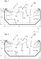
- a spacer 50 according to a first embodiment is shown in Fig. 1 .
- Such a spacer 50 is designed and adapted to be mounted in an IGU 40 in the way shown in Fig. 5 or 8 instead of a spacer of the type shown in Fig. 5 or 7 or 8 .
- the side of the spacer 50 which is the upper side in Fig. 1 and which is the non-diffusion proof side and thus designed to face the gas filled interspace 53 in the mounted state, is named the inner side of the spacer in the following.
- the spacer extends with an essentially constant cross-section x-y in the longitudinal direction z with an overall height h1 in the height direction y perpendicular to the longitudinal direction z.
- the side walls 11, 12 having a predetermined distance w1 between their lateral outer sides in the width direction x in a state in which no external pressure force or external tensional force is applied to the side walls.
- the spacer 50 has a generally rectangular cross section perpendicular to the longitudinal direction z.
- the spacer 50 comprises a spacer profile body 10.
- the spacer profile body 10 may be made by extrusion of polyamide 66 with 25 % glass fibre reinforcement (PA66 GF 25) or could also be made of polypropylene PP with or without fibre reinforcement or of any other suitable materials.
- the profile body 10 extends in the longitudinal direction z with the two lateral side walls 11, 12 and an inner wall 14 located on the inner side of the spacer and adapted to face the gas filled interspace 53 in the mounted state.
- the two side walls 11, 12 are separated by a distance in the traverse (width) direction x and extend essentially in the height direction y towards the inner side of the spacer up to inner ends 11e, 12e.
- the side walls 11, 12 are adapted to face the glazing panes 51, 52 in the width direction x perpendicular to the longitudinal direction z and to the height direction y.
- the side walls 11, 12 are directly connected with and by the inner wall 14 on the inner side of the spacer.
- a one-piece diffusion barrier film 30 is formed on the outer side of the spacer which faces away from the gas filled interspace 53 (from the inner side of the spacer) and on the side walls 11, 12.
- the diffusion barrier film 30 may be formed partly in the side walls and/or only on part of the side walls or only on the outer side of the spacer.
- the diffusion barrier film 30 may be made of metal like stainless steel or of another diffusion proof material like diffusion-proof multilayer foils.
- the diffusion barrier film 30 may optionally be designed to also serve as a reinforcement element.
- Fig. 1 shows wires 31 in the corner portions on the inner side as other optional reinforcement elements.
- An outer wall 13 may optionally be formed on the outer side of the spacer, as shown in Fig. 1 .
- the diffusion barrier film 30 is formed on the outer wall 13 as shown in Fig. 1 .
- the outer wall 13 and the side walls 11, 12 may either be directly connected with and by the outer wall 13 or by interposed slant (oblique) wall sections, which may optionally be concave or convex in addition, as shown on Fig. 1 to 4 and 7 to 14 .
- a chamber 20 is formed for accommodating hygroscopic (desiccating) material.
- the chamber 20 is defined in cross-sectional view perpendicular to the longitudinal direction z by on its respective lateral sides the side walls 11, 12 and on its side facing the interspace 53 by the inner wall 14. Openings 15 are formed in the inner wall 14 (not shown in Fig. 1 but see Fig. 5 ), so that the inner wall 14 is formed to be non-diffusion-proof allowing gas exchange between the gas filled interspace 53 and the chamber 20.
- the inner wall 14 comprises a recess portion 14rs having a depth dr in the height direction y and a width w2 in the width direction x allowing to change the length of the inner wall 14 in the width direction in response to an external pressure force or external tensional force applied to the side walls 11, 12 as it occurs in case of climate stress.
- the recess portion 14rs has, seen in the cross-section x-y perpendicular to the longitudinal direction z, a rectangular shape with three side portions 14sl, 14sh, 14sr formed by the inner wall 14 and an open side facing the gas filled interspace 53 in the mounted state.
- the recess portion 14rs has a depth dr in the height direction y in a range of 1.5 mm to 2 mm, such as 1, 5 mm or 1.75 mm or 2 mm, and a width w2 in the width direction x in a range of 2.5 mm to 4 mm, such as 2.5 mm or 3 mm or 3.5 mm or 4 mm. These values are especially suitable for spacers with a width w1 of 10 to 20 mm and a height h1 of 6 to 8 mm.
- the depth dr of the (rectangular cross section) recess portion 14rs can be up to 50% of overall height h1 of spacer profile and the width w2 can reach up to 50% of overall width w1 of spacer profile.
- the recess portion 14rs is centered in the inner wall 14 in the width direction x. It is also possible that the recess portion 14rs has an off-center position, especially if the applied forces may be not symmetrical. However, the centered position is preferred.
- the recess portion 14rs of the inner wall 14 has a wall thickness which is in a range 20% to 80% of the wall thickness of the other parts of the inner wall 14.
- the wall thickness of the inner wall is, e.g. 0.5 mm and the thickness of the recess portion is 0.3 mm, i.e., 60%.
- transitions of the side portions14sl, 14sh, 14sr and the other portions of the inner wall 14 are preferably rounded as shown in Fig. 1 .
- the depth dr of the recess portion 14rs in the height direction y is measured relative to a straight imaginary line connecting the ends of the connections between the inner wall 14 and the side walls 11, 12 in the height direction y.
- This imaginary line is not completely shown in Fig. 1 but the end of the imaginary line is shown as hatched line in Fig. 1 at the upper end of the arrow for measure dr.
- the spacer is configured such that its outer side formed by either a diffusion barrier 30 or an outer wall 13 or a combination of a diffusion barrier and at least a section of an outer wall maintains its length in the width direction x in response to an external pressure force or external tensional force applied to the side walls 11, 12 as it occurs in case of climate stress.
- the elements forming the outer side do not allow to change the length of the outer side in the width direction x in response to an external pressure force or external tensional force applied to the side walls 11, 12 as it occurs in case of climate stress.
- the diffusion barrier 30 is designed to provide this characteristic of keeping the length in width direction x constant, this can be achieved by using a material like metal or a multilayer foil of sufficient thickness providing the necessary strength to the outer side of the spacer.
- the minimum thickness is about 0.06 mm.
- shape of metal films or foils can help to keep the length in width direction x constant.
- the metal film or foil can, for example, have corrugations or undulations in width direction x (perpendicular to longitudinal direction) to increase resistance and strength of the metal film/foil in this direction. If the outer wall 13 is designed to provide this characteristic of keeping the length in width direction x constant, this can be achieved by a corresponding thickness and/or by reinforcements like glass fibres or other fibres.
- Combinations of the above measures are also possible such as, e.g., metal film sections at the outer side corner portions and a corresponding multilayer foil inbetween the metal film sections on the outer side, or a foamed outer wall with glass fibre reinforcement of 30 to 40% while the inner wall is not foamed and comprises no glass fibre reinforcement combined with a multilayer foil on the outer side, etc.
- a combination of a metal diffusion barrier 30 with a sufficient thickness to maintain the length in the width direction x on the outer side and of an outer wall 13 is shown as an example.
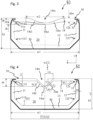
- a spacer 50 according to a second embodiment is shown in Fig. 2 and 4 .
- Fig. 4 dimensions for a specific size of a spacer for a 16 mm nominal width of the interspace between the panes of an IGU are indicated.
- the spacer 50 of the second embodiment differs from the spacer 50 of the first embodiment essentially in that it comprises a recess portion 14rt instead of the recess portion 14rs.
- the recess portion 14rt has, seen in the cross-section x-y perpendicular to the longitudinal direction z, a triangular shape with two side portions 14tl, 14tr and an apex 14ta between the same formed by the inner wall 14 and an open side facing the gas filled interspace 53 in the mounted state.
- the remaining design and features are the same as in the first embodiment unless described differently in the following.
- the inner wall 14 comprises the recess portion 14rt having a depth dr in the height direction y and a width w2 in the width direction x allowing to change the length of the inner wall 14 in the width direction in response to an external pressure force or external tensional force applied to the side walls 11, 12 as it occurs in case of climate stress.
- the recess portion 14rt has, seen in the cross-section x-y perpendicular to the longitudinal direction z, the above described triangular shape.
- the recess portion 14rt has a depth dr in the height direction y in a range of 1.5 mm to 2.5 mm, such as 1, 5 mm or 1.75 mm or 2 mm or 2.25 mm or 2.5 mm, and a width w2 in the width direction x in a range of 3.5 mm to 5 mm, such as 3.5 mm or 4 mm or 4.5 mm or 5 mm. These values are especially suitable for spacers with a width w1 of 10 to 20 mm and a height h1 of 6 to 8 mm.
- the depth dr of the (triangular cross section) recess portion 14rt can reach up to 50% of overall height h1 of spacer profile and the width w2 can be up to 60% of overall width w1 of spacer profile.
- the recess portion 14rt of the inner wall 14 has a wall thickness which is in a range 20% to 80% of the wall thickness of the other parts of the inner wall 14.
- the wall thickness of the inner wall is, e.g. 0.5 mm and the thickness of the recess portion is 0.3 mm, i.e., 60%.
- transitions of the side portions 14tl, 14tr and an apex 14ta and the other portions of the inner wall 14 are preferably rounded as shown in Fig. 2 and 4 .
- the depth dr of the recess portion 14rt in the height direction y is measured relative to a straight imaginary line connecting the ends of the connections between the inner wall 14 and the side walls 11, 12 in the height direction y.
- This imaginary line is not completely shown in Fig. 2 but the end of the imaginary line is shown as hatched line in Fig. 2 at the upper end of the arrow for measure dr.
- a spacer 50 according to a third embodiment is shown in Fig. 3 .
- the spacer 50 of the third embodiment differs from the spacer 50 of the first embodiment essentially in that it comprises a recess portion 14rc instead of the recess portion 14rs.
- the recess portion 14rc has, seen in the cross-section x-y perpendicular to the longitudinal direction z, a curved shape with curved portions 14cl, 14cr and a thin portion 14ct formed by the inner wall 14 and a convex curvature facing away from the gas filled interspace 53 in the mounted state.
- the curvature could also be described as concave seen from the chamber 20.
- the remaining design and features are the same as in the first embodiment unless described differently in the following.
- the inner wall 14 comprises the recess portion 14rc having a depth dr in the height direction y and a width w2 in the width direction x allowing to change the length of the inner wall 14 in the width direction in response to an external pressure force or external tensional force applied to the side walls 11, 12 as it occurs in case of climate stress.
- the recess portion 14rc has a depth dr in the height direction y in a range of 1.5 mm to 2.5 mm, such as 1, 5 mm or 1.75 mm or 2 mm or 2.25 mm or 2.5 mm, and a width w2 in the width direction x in a range of 4 mm to 9 mm, such as 4 mm or 5 mm or 6 mm or 7 mm or 8 mm or 9 mm. These values are especially suitable for spacers with a width w1 of 10 to 20 mm and a height h1 of 6 to 8 mm.
- the depth dr of the (curved cross section) recess portion 14rc can be up to 50% of overall height h1 of spacer profile and the width w2 can reach up to 80% of overall width w1 of spacer profile.
- the recess portion 14rc of the inner wall 14 has a minimum wall thickness dt which is in a range 20% to 80% of the wall thickness of the other parts of the inner wall 14.
- the wall thickness diw of the inner wall is, e.g. 0.8 mm and the thickness of the recess portion is 0.4 mm, i.e., 50%.
- the depth dr of the recess portion 14rc in the height direction y is measured relative to a straight imaginary line connecting the ends of the connections between the inner wall 14 and the side walls 11, 12 in the height direction y.
- This imaginary line is not completely shown in Fig. 3 but the end of the imaginary line is shown as hatched line in Fig. 3 at the upper end of the arrow for measure dr.
- the IGU of Fig. 5 or 8 is subject to heating and cooling due to external conditions. If the IGU is heated, the gas in the interspace 53 is heated and, because the interspace is hermetically sealed, the gas pressure in the interspace 53 increases in comparison to the (atmospheric) pressure outside the IGU. The result are pressure forces acting on the glazing panes and bending the same to convex shapes as shown in Fig. 9 . If the IGU is cooled, the opposite effect occurs. The gas in the interspace 53 is cooled and, because the interspace is hermetically sealed, the gas pressure in the interspace 53 decreases in comparison to the (atmospheric) pressure outside the IGU. The result are pressure forces acting on the glazing panes and bending the same to concave shapes as shown in Fig. 10 .
- tensile stress forces F TS act on the primary sealing 61 in the region at the inner ends 11e, 12e of the lateral side walls 11, 12 of the spacer 50 located at the inner side facing the interspace 53 as shown in Fig. 9 .
- These tensile stress forces F TS may cause a separation of the primary sealing from the glazing pane and/or the spacer and thus damage the sealing effect, which is detrimental to the long term life if IGUs due to cycling behaviour.
- the pressure forces F P acting on the spacer at the remote ends 11f, 12f of the side walls 11, 12 of the spacer remote to the interspace 53 and on the secondary sealing are not so problematic although they cause stress (compression) to primary and secondary sealing materials.
- tensile stress forces F TS act on the primary sealing 61 in the region at the remote ends 11f, 12f of the side walls 11, 12 of the spacer remote to the interspace 53 and on the secondary sealing as shown in Fig. 10 .
- These tensile stress forces F TS may cause a separation of the primary and/or secondary sealings from the glazing pane and/or the spacer and thus damage the sealing effect, which is detrimental to the long term life if IGUs due to cycling behaviour.
- the pressure forces F P acting on the spacer in the region at the inner ends 11e, 12e of the lateral side walls 11, 12 of the spacer 50 located at the inner side facing the interspace 53 are not so problematic although they cause stress (compression) to primary and secondary sealing materials.
- the effects of heating and cooling an IGU may be caused by usual climate changes in winter and summer, the weather, the change of day and night, or air condition and heating. Therefore, the effects occur alternating and threaten the intended lifetime of IGUs.
- the recess portion 14rs of the first embodiment allows the inner ends 11e, 12e of the side walls 11, 12 to move away from each other in reaction to tensile stress forces F TS shown in Fig. 9 .
- the recess portion 14rs also allows the inner ends 11e, 12e of the side walls 11, 12 to move towards each other in reaction to pressure forces F P shown in Fig. 10 .
- the reason is that the recess portion allows a change of the length of the inner wall 14 in the width direction in response to an external pressure force or external tensional force applied to the side walls 11, 12 as it occurs in case of climate stress.
- the recess portion 14rs has three side portions 14sl, 14sh, 14sr, which can change their relative angles and the relative angles to the other portions of the inner wall 14 under tension or pressure. By change of the relative angles, the length of the inner wall 14 inevitably varies in the width direction x.
- the recess portion 14rs allows to change the distance between the lateral outer sides of the side walls 11, 12 at the inner ends 11e, 12e from the predetermined distance w1 in a state in which an external pressure force or an external tensional force is applied to the side walls.
- the distance between the lateral outer sides of the side walls 11, 12 at the remote ends 11f, 12f is not changed from the predetermined distance w1 in a state in which an external pressure force or an external tensional force is applied to the side walls.
- an improved spacer for IGUs is provided with superior climate stress compensation characteristics.
- Such improved spacer is flexible enough by its design to reduce the stress on the primary and also the secondary sealing material such that gas loss is reduced and the overall lifetime of the IGU can be extended. Additionally, less amount of secondary sealing material can be used thus improving the thermal performance of the IGU.
- the relative angles can change in a similar way in response to an external pressure force or external tensional force applied to the side walls 11, 12 as it occurs in case of climate stress.
- the length change of the inner wall 14 is obtained by straightening the curvature or increasing the curvature.
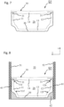
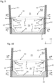
- Fig. 11 shows a partial cross-sectional view of the spacer of the third embodiment shown in Fig. 3 exemplifying the effect of increased gas pressure in an IGU (see Fig. 9 ) to this spacer
- Fig. 12 shows a partial cross-sectional view of the spacer of the embodiment shown in Fig. 3 exemplifying the effect of reduced gas pressure in an IGU (see Fig. 10 ) to this spacer.
- the reference signs and the corresponding parts and meanings are the same except if differences are explained below.
- the inner wall 14 with the (in this embodiment curved and concave) recess portion 14rc and the reduced wall thickness dt of the inner wall section forming the recess portion.
- the inner ends 11e, 12e of the side walls 11, 12 can move away from each other by a distance of 2 ⁇ w1 (indicated as ⁇ w1 l on the left side and as ⁇ w1 r on the right side in Fig. 11 ) thus increasing the length of the inner wall 14 in the width direction x.
- the distances ⁇ w1 i are a result of straightening the curved recess portion 14rc under the tensile stress caused by the tensile stress forces F TS increasing the length of the curved recess portion 14rc in the width direction x by a distance of 2 ⁇ w2 (indicated as ⁇ w2 l on the left side and as ⁇ w2 r on the right side in Fig. 11 ).
- the depth dr of the recess portion 14rc in height direction y is reduced by ⁇ dr.
- the shape of the recess portion 14rc without the acting forces is shown as hatched lines in Fig. 11 . If the forces do not act anymore, usually because the temperatures changed and the increased pressure does not act anymore, the recess portion returns to this "force-free" state.
- the recess portion 14rc is configured as an elastically deformable portion enabling/allowing the change of length of the inner wall 14.
- the remote ends 11f, 12f of the side walls 11, 12 do not move in reaction to the reaction to the pressure forces F P shown in Fig. 9 .
- the width w1 remains unchanged on the outer side of the spacer.
- pressure forces F P act on the spacer in the region at the inner ends 11e, 12e of the lateral side walls 11, 12 of the spacer 50 located at the inner side facing the interspace 53 as shown in Fig. 10 and 12
- tensile stress forces F TS act on the primary sealing 61 in the region at the remote ends 11f, 12f of the side walls 11, 12 of the conventional spacer remote to the interspace 53 and on the secondary sealing as shown in Fig. 10 .
- the recess portion 14rc of the third embodiment allows the inner ends 11e, 12e of the side walls 11, 12 to move towards each other in reaction to pressure forces F P as shown in Fig. 12 .
- This is enabled/allowed by the design of the inner wall 14 with the (in this case curved and concave) recess 14rc and the reduced wall thickness dt of the inner wall section forming the the recess.
- the inner ends 11e, 12e of the side walls 11, 12 can move towards each other by a distance of 2 ⁇ w1 (indicated as ⁇ w1 l on the left side and as ⁇ w1 r on the right side in Fig. 12 ) thus reducing the length of the inner wall 14 in the width direction x.
- the distances ⁇ w1 i are a result of increasing the curvature of the curved recess portion under the pressure caused by the pressure forces F P reducing the length of the curved recess portion 14rc by a distance of 2 ⁇ w2 (indicated as ⁇ w2 l on the left side and as ⁇ w2 r on the right side in Fig. 12 ).
- the depth dr of the recess portion 14rc in height direction y is increased by ⁇ dr.
- the shape of the recess portion 14rc without the acting forces is shown as hatched lines in Fig. 12 . If the forces do not act anymore, usually because the temperatures changed and the reduced pressure does not act anymore, the recess portion returns to this "force-free" state.
- the recess portion 14rc is configured as an elastically deformable portion enabling/allowing the change of length of the inner wall 14.
- the recess portion 14rs, 14rt, 14rc is adapted to change the length of the inner wall 14 by elastic deformation of the recess portion 14rs, 14rt, 14rc.
- the primary sealing 61 can be further protected by means of a special design of the inner wall 14 and the side walls 11, 12 of the spacer 50.
- Said design is described and shown in WO 2014/063801 A1 on pages 7, 8, and 17 as step-like transition or step with a width h3 and in Fig. 1 (corresponding to paragraphs [0035] and [0089] and Fig. 1 of EP 2 780 528 B1 ), which corresponding disclosure is herein incorporated by reference.
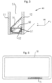
- Fig. 13 and 14 show an application of this special design with a step-like transition or step or protrusion in the width direction x to the present teachings exemplified by the second embodiment.
- the design can be applied to all embodiments.
- a corresponding step is also shown in DE 20 2016 008 421 U1 .
- Spacer 50 of the fourth embodiment shown in Fig. 13 and 14 differs from the spacer of the second embodiment shown in Fig. 2 in that the spacer comprises a transition between the inner wall 14 and the side walls 11, 12 at the lateral outer sides in form of projections (or extensions or shoulders) 11p, 12p in the width direction x which create a step-like transition.
- the width wp of each projection 11p, 12p corresponds to the width of primary sealing 61 in the assembled state of the IGU as shown in Fig. 14 .
- the width wp is preferably in a range from 0.01 mm to 1 mm, more preferably between 0.05 mm and 0.5 mm, more preferably between 0.1 mm and 0.4 mm, e.g., 0.2 mm or 0.25 mm or 0.3 mm or 0.35mm.
- the width wp of one protrusion is preferably selected to correspond to the width of the primary sealing 61 on one lateral side in the width direction x.
- the total width w1 of the spacer 50 measured between outermost lateral side surfaces of the projections 11p, 12p in the assembled state of the IGU in a state in which no pressure forces F P or tensile stress forces F TS forces due to climate conditions are present corresponds to distance (nominal width) between the window panes 51, 52.
- Such a step-like transition/protrusion 11p, 12p creates a cavity between the corresponding adjacent glass pane 51, 52 and the corresponding side wall 11, 12 of spacer in which the primary sealing 61 is accommodated.
- the projections 11p, 12p are intended to contact the glass panes 51, 52 and to transmit the pressure forces F P or tensile stress forces F TS to the spacer without stressing the primary sealing or at least significantly reducing the stress.
- the primary sealing 61 is an intermediate layer between the glass panes and the side walls of spacer 50 and acts as a force transmitting layer with potentially detrimental consequences on its integrity and durability as sealing agent.
- the primary sealing 61 is relieved of the duty to transmit these forces and can better fulfill its primary function, i.e. to be a sealing layer between the glass panes and the side walls of the spacer.
- the shoulders prevent the primary sealing 61 from being squeezed out and moving into the interspace 53 (both during IGU manufacturing process and also during lifetime of IGU due to the above described climate effects), which is undesired and aesthetically not pleasant.
- the spacer of present teachings having a recess portion in the inner wall should in principle be as flexible as or more flexible than the primary sealing due to the provision of the recess in the inner wall, in order not to stress the primary sealing.
- the above described special design of the projections relieves the primary sealing because protrusions directly take the force exerted by the glass panes that would otherwise have to be taken by the primary sealing, at least partially.
- Another means to make the spacer of the present teachings as flexible as or more flexible than the primary sealing is to provide a foamed inner wall 14 in addition to the recess in the inner wall.
- the dimensions and shapes of the recesses have been described as especially suitable for spacers with a width w1 in a range from 10 mm to 20 mm and a height h1 in a range from 6 mm to 8 mm.
- the teachings are also applicable to spacers with a width w1 up to 32 mm or up to 40 mm and/or with a width w1 down to 8 mm and with a height h1 up to 10 mm.
Landscapes
- Engineering & Computer Science (AREA)
- Structural Engineering (AREA)
- Civil Engineering (AREA)
- Architecture (AREA)
- Securing Of Glass Panes Or The Like (AREA)
- Joining Of Glass To Other Materials (AREA)
Description
- The present invention relates to a spacer for insulating glass units, especially but not only suitable for compensating climate stress in insulating glass units.
- Heating and cooling of an insulting glazing unit IGU may be caused by usual climate changes in winter and summer, the weather, the change of day and night, or air conditioning and heating. Heating and cooling or wind pressure may cause climate stress in form of significant pressure differences between the gas volume in an IGU and the outside atmosphere and corresponding bending or curvatures of the glazing panes of the IGU. This results in high stress on the edge bond of the IGU, which leads to escaping of internal gas or to penetration of water. Both significantly reduce the performance of the IGU. In case of climate loads, the secondary sealant needs to act as spring and damper. The stiffer the spacer is, the more the secondary sealant needs to compensate. Otherwise the stress on primary sealant is too high.
-
US 6,823,644 andUS 2006/201105 A1 disclose a spacer design for compensating climate stress at the spacer in an insulating glass unit (IGU), in which sections of the inner wall facing the interspace between glazing panes of the IGU, are separated and movable relative to each other.US 2007/0077376 A1 also discloses such a spacer design as prior art and additionally spacer designs in which at least one lateral side wall adapted to face a glazing pane is separated from an adjacent separate side wall of a chamber for desiccant. -
WO 2004/038155 A1 discloses a spacer design with a curved wall design for compensating climate stress at the spacer in an insulating glass unit (IGU).WO 2014/063801 A1 discloses a spacer design with a curved wall design. -
WO 2004/05783 A2 -
EP 2 679 758 A1Fig. 5 to 12 spacer designs for allowing relative movements of glazing panes towards and away from each other and movements parallel to each other. - It is an object of the present invention to provide an improved spacer design for compensating climate stress in an insulating glass unit (IGU).
- This object is achieved by a spacer for insulating glass units according to claim 1 or 3 or an IGU according to
claim 15 or a window or door or facade element according to claim 16. - Further developments are given in the dependent claims.
- Further features and advantages will become apparent from the descriptions of embodiments referring to the drawings, which show:
- Fig. 1
- a cross-sectional view of a spacer according to according to a first embodiment perpendicular to its longitudinal direction;
- Fig. 2
- a cross-sectional view of a spacer according to according to a second embodiment perpendicular to its longitudinal direction;
- Fig. 3
- a cross-sectional view of a spacer according to according to a third embodiment perpendicular to its longitudinal direction;
- Fig. 4
- a cross-sectional view of the spacer according to according to the second embodiment perpendicular to its longitudinal direction with indication of dimensions;
- Fig. 5
- a partial perspective cross-sectional view of an insulating glazing unit with a spacer;
- Fig. 6
- a side view, partially cut away, of a spacer frame bent from a spacer profile;
- Fig. 7
- a cross-sectional view of a conventional spacer perpendicular to its longitudinal direction;
- Fig. 8
- a partial cross-sectional view of an insulating glazing unit with the spacer of
Fig. 7 ; - Fig. 9
- a partial cross-sectional view of an insulating glazing unit corresponding to
Fig. 8 exemplifying the effect of increased gas pressure in the IGU; - Fig. 10
- a partial cross-sectional view of an insulating glazing unit corresponding to
Fig. 8 exemplifying the effect of reduced gas pressure in the IGU; - Fig. 11
- a partial cross-sectional view of a spacer of the embodiment shown in
Fig. 3 exemplifying the effect of increased gas pressure in an IGU to this spacer; - Fig. 12
- a partial cross-sectional view of a spacer of the embodiment shown in
Fig. 3 exemplifying the effect of reduced gas pressure in an IGU to this spacer; . - Fig. 13
- a cross-sectional view of a spacer according to according to a fourth embodiment perpendicular to its longitudinal direction; and
- Fig. 14
- a partial cross-sectional view of an insulating glazing unit with the spacer of
Fig. 13 . -
Fig. 5 shows a partial perspective view andFig. 8 shows a cross-sectional view of an insulating glazing unit (IGU) 40 with aspacer 50. The IGU 40 comprises twoglazing panes spacer 50 extends in a longitudinal direction z along the edges of theglazing panes - As shown in
Fig. 6 , thespacer 50 is used to form a spacer frame, e. g. by cold-bending the spacer profile into a frame shape and connecting the ends with alinear connector 54 as known in the art. Other ways to form a spacer frame like cutting linear pieces of spacer frame parts and connecting the same via corner connectors are also possible as known in the art. - The spacer (frame) 50 is mounted at the edges of the two spaced
glazing panes Fig. 5 ,7 and 8 , thespacer 50 comprises side walls formed as attachment bases to be adhered with the inner sides of theglazing panes space 53 between the glazing panes is thus defined by the twoglazing panes spacer profile 50. The inner side of thespacer profile 50 faces theintervening space 53 between theglazing panes space 53 between the glazing panes in the height direction y, a mechanically stabilizing sealing material (secondary sealing compound) 62, for example based upon polysulfide, polyurethane or silicon, is introduced into the remaining, empty space between the inner sides of the window panes in order to fill the empty space. This sealing compound also protects adiffusion barrier layer 30 provided at least on the outer side of thespacer 50. It is also possible to use other possibilities than a gasdiffusion barrier layer 30 to provide gas diffusion-proof characteristics like selecting corresponding gas diffusion-tight materials for the body of the spacer profile. - The
interspace 53 between theglazing panes interspace 53 is present between theglazing panes - As shown in
Fig. 5 ,7 and 8 , thespacer 50 comprises aspacer profile body 10. Theside walls Fig. 5 ,8 ). In addition, thespacer 50 is adhered to the respective inner sides of the glazing panes via the secondary sealing compound 62 (seeFig. 5 ,8 ). - A
spacer 50 according to a first embodiment is shown inFig. 1 . Such aspacer 50 is designed and adapted to be mounted in anIGU 40 in the way shown inFig. 5 or8 instead of a spacer of the type shown inFig. 5 or7 or 8 . The side of thespacer 50, which is the upper side inFig. 1 and which is the non-diffusion proof side and thus designed to face the gas filledinterspace 53 in the mounted state, is named the inner side of the spacer in the following. - The spacer extends with an essentially constant cross-section x-y in the longitudinal direction z with an overall height h1 in the height direction y perpendicular to the longitudinal direction z. The
side walls spacer 50 has a generally rectangular cross section perpendicular to the longitudinal direction z. - As shown in
Fig. 1 , thespacer 50 comprises aspacer profile body 10. Thespacer profile body 10 may be made by extrusion of polyamide 66 with 25 % glass fibre reinforcement (PA66 GF 25) or could also be made of polypropylene PP with or without fibre reinforcement or of any other suitable materials. Theprofile body 10 extends in the longitudinal direction z with the twolateral side walls inner wall 14 located on the inner side of the spacer and adapted to face the gas filledinterspace 53 in the mounted state. - Seen in the cross-section x-y perpendicular to the longitudinal direction z, the two
side walls inner ends side walls glazing panes side walls inner wall 14 on the inner side of the spacer. - A one-piece
diffusion barrier film 30 is formed on the outer side of the spacer which faces away from the gas filled interspace 53 (from the inner side of the spacer) and on theside walls diffusion barrier film 30 may be formed partly in the side walls and/or only on part of the side walls or only on the outer side of the spacer. Thediffusion barrier film 30 may be made of metal like stainless steel or of another diffusion proof material like diffusion-proof multilayer foils. Thediffusion barrier film 30 may optionally be designed to also serve as a reinforcement element.Fig. 1 showswires 31 in the corner portions on the inner side as other optional reinforcement elements. - An
outer wall 13 may optionally be formed on the outer side of the spacer, as shown inFig. 1 . In such a case, thediffusion barrier film 30 is formed on theouter wall 13 as shown inFig. 1 . Theouter wall 13 and theside walls outer wall 13 or by interposed slant (oblique) wall sections, which may optionally be concave or convex in addition, as shown onFig. 1 to 4 and7 to 14 . - A
chamber 20 is formed for accommodating hygroscopic (desiccating) material. Thechamber 20 is defined in cross-sectional view perpendicular to the longitudinal direction z by on its respective lateral sides theside walls interspace 53 by theinner wall 14.Openings 15 are formed in the inner wall 14 (not shown inFig. 1 but seeFig. 5 ), so that theinner wall 14 is formed to be non-diffusion-proof allowing gas exchange between the gas filledinterspace 53 and thechamber 20. In addition or in the alternative, to achieve a non-diffusion-proof design, it is also possible to select the material for the entire profile body and/or the inner wall, such that the material permits an equivalent diffusion without the formation of theopenings 15. - The
inner wall 14 comprises a recess portion 14rs having a depth dr in the height direction y and a width w2 in the width direction x allowing to change the length of theinner wall 14 in the width direction in response to an external pressure force or external tensional force applied to theside walls - The recess portion 14rs has, seen in the cross-section x-y perpendicular to the longitudinal direction z, a rectangular shape with three side portions 14sl, 14sh, 14sr formed by the
inner wall 14 and an open side facing the gas filledinterspace 53 in the mounted state. - The recess portion 14rs has a depth dr in the height direction y in a range of 1.5 mm to 2 mm, such as 1, 5 mm or 1.75 mm or 2 mm, and a width w2 in the width direction x in a range of 2.5 mm to 4 mm, such as 2.5 mm or 3 mm or 3.5 mm or 4 mm. These values are especially suitable for spacers with a width w1 of 10 to 20 mm and a height h1 of 6 to 8 mm. In general, the depth dr of the (rectangular cross section) recess portion 14rs can be up to 50% of overall height h1 of spacer profile and the width w2 can reach up to 50% of overall width w1 of spacer profile.
- The recess portion 14rs is centered in the
inner wall 14 in the width direction x. It is also possible that the recess portion 14rs has an off-center position, especially if the applied forces may be not symmetrical. However, the centered position is preferred. - The recess portion 14rs of the
inner wall 14 has a wall thickness which is in arange 20% to 80% of the wall thickness of the other parts of theinner wall 14. The wall thickness of the inner wall is, e.g. 0.5 mm and the thickness of the recess portion is 0.3 mm, i.e., 60%. - The transitions of the side portions14sl, 14sh, 14sr and the other portions of the
inner wall 14 are preferably rounded as shown inFig. 1 . - The depth dr of the recess portion 14rs in the height direction y is measured relative to a straight imaginary line connecting the ends of the connections between the
inner wall 14 and theside walls Fig. 1 but the end of the imaginary line is shown as hatched line inFig. 1 at the upper end of the arrow for measure dr. - The spacer is configured such that its outer side formed by either a
diffusion barrier 30 or anouter wall 13 or a combination of a diffusion barrier and at least a section of an outer wall maintains its length in the width direction x in response to an external pressure force or external tensional force applied to theside walls side walls diffusion barrier 30 is designed to provide this characteristic of keeping the length in width direction x constant, this can be achieved by using a material like metal or a multilayer foil of sufficient thickness providing the necessary strength to the outer side of the spacer. In case of stainless steel, the minimum thickness is about 0.06 mm. Also the shape of metal films or foils can help to keep the length in width direction x constant. The metal film or foil can, for example, have corrugations or undulations in width direction x (perpendicular to longitudinal direction) to increase resistance and strength of the metal film/foil in this direction. If theouter wall 13 is designed to provide this characteristic of keeping the length in width direction x constant, this can be achieved by a corresponding thickness and/or by reinforcements like glass fibres or other fibres. Combinations of the above measures are also possible such as, e.g., metal film sections at the outer side corner portions and a corresponding multilayer foil inbetween the metal film sections on the outer side, or a foamed outer wall with glass fibre reinforcement of 30 to 40% while the inner wall is not foamed and comprises no glass fibre reinforcement combined with a multilayer foil on the outer side, etc. InFig. 1 , a combination of ametal diffusion barrier 30 with a sufficient thickness to maintain the length in the width direction x on the outer side and of anouter wall 13 is shown as an example. - A
spacer 50 according to a second embodiment is shown inFig. 2 and4 . InFig. 4 , dimensions for a specific size of a spacer for a 16 mm nominal width of the interspace between the panes of an IGU are indicated. Thespacer 50 of the second embodiment differs from thespacer 50 of the first embodiment essentially in that it comprises a recess portion 14rt instead of the recess portion 14rs. - The recess portion 14rt has, seen in the cross-section x-y perpendicular to the longitudinal direction z, a triangular shape with two side portions 14tl, 14tr and an apex 14ta between the same formed by the
inner wall 14 and an open side facing the gas filledinterspace 53 in the mounted state. The remaining design and features are the same as in the first embodiment unless described differently in the following. - The
inner wall 14 comprises the recess portion 14rt having a depth dr in the height direction y and a width w2 in the width direction x allowing to change the length of theinner wall 14 in the width direction in response to an external pressure force or external tensional force applied to theside walls - The recess portion 14rt has, seen in the cross-section x-y perpendicular to the longitudinal direction z, the above described triangular shape.
- The recess portion 14rt has a depth dr in the height direction y in a range of 1.5 mm to 2.5 mm, such as 1, 5 mm or 1.75 mm or 2 mm or 2.25 mm or 2.5 mm, and a width w2 in the width direction x in a range of 3.5 mm to 5 mm, such as 3.5 mm or 4 mm or 4.5 mm or 5 mm. These values are especially suitable for spacers with a width w1 of 10 to 20 mm and a height h1 of 6 to 8 mm. In general, the depth dr of the (triangular cross section) recess portion 14rt can reach up to 50% of overall height h1 of spacer profile and the width w2 can be up to 60% of overall width w1 of spacer profile.
- The recess portion 14rt of the
inner wall 14 has a wall thickness which is in arange 20% to 80% of the wall thickness of the other parts of theinner wall 14. The wall thickness of the inner wall is, e.g. 0.5 mm and the thickness of the recess portion is 0.3 mm, i.e., 60%. - The transitions of the side portions 14tl, 14tr and an apex 14ta and the other portions of the
inner wall 14 are preferably rounded as shown inFig. 2 and4 . - The depth dr of the recess portion 14rt in the height direction y is measured relative to a straight imaginary line connecting the ends of the connections between the
inner wall 14 and theside walls Fig. 2 but the end of the imaginary line is shown as hatched line inFig. 2 at the upper end of the arrow for measure dr. - A
spacer 50 according to a third embodiment is shown inFig. 3 . Thespacer 50 of the third embodiment differs from thespacer 50 of the first embodiment essentially in that it comprises a recess portion 14rc instead of the recess portion 14rs. - The recess portion 14rc has, seen in the cross-section x-y perpendicular to the longitudinal direction z, a curved shape with curved portions 14cl, 14cr and a thin portion 14ct formed by the
inner wall 14 and a convex curvature facing away from the gas filledinterspace 53 in the mounted state. The curvature could also be described as concave seen from thechamber 20. The remaining design and features are the same as in the first embodiment unless described differently in the following. - The
inner wall 14 comprises the recess portion 14rc having a depth dr in the height direction y and a width w2 in the width direction x allowing to change the length of theinner wall 14 in the width direction in response to an external pressure force or external tensional force applied to theside walls - The recess portion 14rt has, seen in the cross-section x-y perpendicular to the longitudinal direction z, the above described curved shape.
- The recess portion 14rc has a depth dr in the height direction y in a range of 1.5 mm to 2.5 mm, such as 1, 5 mm or 1.75 mm or 2 mm or 2.25 mm or 2.5 mm, and a width w2 in the width direction x in a range of 4 mm to 9 mm, such as 4 mm or 5 mm or 6 mm or 7 mm or 8 mm or 9 mm. These values are especially suitable for spacers with a width w1 of 10 to 20 mm and a height h1 of 6 to 8 mm. In general, the depth dr of the (curved cross section) recess portion 14rc can be up to 50% of overall height h1 of spacer profile and the width w2 can reach up to 80% of overall width w1 of spacer profile.
- The recess portion 14rc of the
inner wall 14 has a minimum wall thickness dt which is in arange 20% to 80% of the wall thickness of the other parts of theinner wall 14. The wall thickness diw of the inner wall is, e.g. 0.8 mm and the thickness of the recess portion is 0.4 mm, i.e., 50%. - The depth dr of the recess portion 14rc in the height direction y is measured relative to a straight imaginary line connecting the ends of the connections between the
inner wall 14 and theside walls Fig. 3 but the end of the imaginary line is shown as hatched line inFig. 3 at the upper end of the arrow for measure dr. - The IGU of
Fig. 5 or8 is subject to heating and cooling due to external conditions. If the IGU is heated, the gas in theinterspace 53 is heated and, because the interspace is hermetically sealed, the gas pressure in theinterspace 53 increases in comparison to the (atmospheric) pressure outside the IGU. The result are pressure forces acting on the glazing panes and bending the same to convex shapes as shown inFig. 9 . If the IGU is cooled, the opposite effect occurs. The gas in theinterspace 53 is cooled and, because the interspace is hermetically sealed, the gas pressure in theinterspace 53 decreases in comparison to the (atmospheric) pressure outside the IGU. The result are pressure forces acting on the glazing panes and bending the same to concave shapes as shown inFig. 10 . - As a result of heating the IGU, tensile stress forces FTS act on the primary sealing 61 in the region at the inner ends 11e, 12e of the
lateral side walls spacer 50 located at the inner side facing theinterspace 53 as shown inFig. 9 . These tensile stress forces FTS may cause a separation of the primary sealing from the glazing pane and/or the spacer and thus damage the sealing effect, which is detrimental to the long term life if IGUs due to cycling behaviour. The pressure forces FP acting on the spacer at the remote ends 11f, 12f of theside walls interspace 53 and on the secondary sealing are not so problematic although they cause stress (compression) to primary and secondary sealing materials. - As a result of cooling the IGU, tensile stress forces FTS act on the primary sealing 61 in the region at the remote ends 11f, 12f of the
side walls interspace 53 and on the secondary sealing as shown inFig. 10 . These tensile stress forces FTS may cause a separation of the primary and/or secondary sealings from the glazing pane and/or the spacer and thus damage the sealing effect, which is detrimental to the long term life if IGUs due to cycling behaviour. The pressure forces FP acting on the spacer in the region at the inner ends 11e, 12e of thelateral side walls spacer 50 located at the inner side facing theinterspace 53 are not so problematic although they cause stress (compression) to primary and secondary sealing materials. - The effects of heating and cooling an IGU may be caused by usual climate changes in winter and summer, the weather, the change of day and night, or air condition and heating. Therefore, the effects occur alternating and threaten the intended lifetime of IGUs.
- The recess portion 14rs of the first embodiment allows the inner ends 11e, 12e of the
side walls Fig. 9 . The recess portion 14rs also allows the inner ends 11e, 12e of theside walls Fig. 10 . The reason is that the recess portion allows a change of the length of theinner wall 14 in the width direction in response to an external pressure force or external tensional force applied to theside walls inner wall 14 under tension or pressure. By change of the relative angles, the length of theinner wall 14 inevitably varies in the width direction x. - In other words, the recess portion 14rs allows to change the distance between the lateral outer sides of the
side walls side walls - Thus, an improved spacer for IGUs is provided with superior climate stress compensation characteristics. Such improved spacer is flexible enough by its design to reduce the stress on the primary and also the secondary sealing material such that gas loss is reduced and the overall lifetime of the IGU can be extended. Additionally, less amount of secondary sealing material can be used thus improving the thermal performance of the IGU.
- The same applies to the recess portion 14rt of the second embodiment, which is the presently preferred embodiment. In the second embodiment, the relative angles can change in a similar way in response to an external pressure force or external tensional force applied to the
side walls - Essentially the same also applies to the third embodiment. Due to the curved design of the recess portion 14rc, the length change of the
inner wall 14 is obtained by straightening the curvature or increasing the curvature. - The above described effects are shown for the third embodiment in
Fig. 11 and 12 , as described below. -
Fig. 11 shows a partial cross-sectional view of the spacer of the third embodiment shown inFig. 3 exemplifying the effect of increased gas pressure in an IGU (seeFig. 9 ) to this spacer, andFig. 12 shows a partial cross-sectional view of the spacer of the embodiment shown inFig. 3 exemplifying the effect of reduced gas pressure in an IGU (seeFig. 10 ) to this spacer. The reference signs and the corresponding parts and meanings are the same except if differences are explained below. - As a result of increased gas pressure in the IGU, tensile stress forces FTS act on the primary sealing 61 in the region at the inner ends 11e, 12e of the
lateral side walls spacer 50 located at the inner side facing theinterspace 53 as shown inFig. 9 and11 . Different from the conventional design shown inFig. 9 , the recess portion 14rc of the third embodiment allows the inner ends 11e, 12e of theside walls Fig. 11 . - This movement is enabled/allowed by the design of the
inner wall 14 with the (in this embodiment curved and concave) recess portion 14rc and the reduced wall thickness dt of the inner wall section forming the recess portion. As illustrated inFig. 11 , the inner ends 11e, 12e of theside walls Fig. 11 ) thus increasing the length of theinner wall 14 in the width direction x. The distances Δw1i are a result of straightening the curved recess portion 14rc under the tensile stress caused by the tensile stress forces FTS increasing the length of the curved recess portion 14rc in the width direction x by a distance of 2Δw2 (indicated as Δw2l on the left side and as Δw2r on the right side inFig. 11 ). The depth dr of the recess portion 14rc in height direction y is reduced by Δdr. - The shape of the recess portion 14rc without the acting forces is shown as hatched lines in
Fig. 11 . If the forces do not act anymore, usually because the temperatures changed and the increased pressure does not act anymore, the recess portion returns to this "force-free" state. In other words, the recess portion 14rc is configured as an elastically deformable portion enabling/allowing the change of length of theinner wall 14. - On the other hand, the remote ends 11f, 12f of the
side walls Fig. 9 . In other words, due to the non-elastic configuration of the outer side of the spacer, in this case thebarrier film 30 and theouter wall 13, the width w1 remains unchanged on the outer side of the spacer. - As a consequence, the danger that the tensile stress forces FTS could cause a separation of the primary sealing 61 from the glazing pane and/or the spacer at the inner ends is overcome or at least significantly reduced, different from the case shown in
Fig. 9 , because the movement of the inner ends due to the increased length of theinner wall 14 relieves this stress and thus prevents a damage of the sealing effect. - As a result of reduced gas pressure in the IGU, pressure forces FP act on the spacer in the region at the inner ends 11e, 12e of the
lateral side walls spacer 50 located at the inner side facing theinterspace 53 as shown inFig. 10 and12 , while tensile stress forces FTS act on the primary sealing 61 in the region at the remote ends 11f, 12f of theside walls interspace 53 and on the secondary sealing as shown inFig. 10 . - The recess portion 14rc of the third embodiment allows the inner ends 11e, 12e of the
side walls Fig. 12 . This is enabled/allowed by the design of theinner wall 14 with the (in this case curved and concave) recess 14rc and the reduced wall thickness dt of the inner wall section forming the the recess. As illustrated inFig. 12 , the inner ends 11e, 12e of theside walls Fig. 12 ) thus reducing the length of theinner wall 14 in the width direction x. The distances Δw1i are a result of increasing the curvature of the curved recess portion under the pressure caused by the pressure forces FP reducing the length of the curved recess portion 14rc by a distance of 2Δw2 (indicated as Δw2l on the left side and as Δw2r on the right side inFig. 12 ). The depth dr of the recess portion 14rc in height direction y is increased by Δdr. - The shape of the recess portion 14rc without the acting forces is shown as hatched lines in
Fig. 12 . If the forces do not act anymore, usually because the temperatures changed and the reduced pressure does not act anymore, the recess portion returns to this "force-free" state. In other words, the recess portion 14rc is configured as an elastically deformable portion enabling/allowing the change of length of theinner wall 14. - As a result, there will be no or significantly reduced (in comparison to the conventional spacer of
Fig. 10 ) tensile stress forces FTS acting on the remote ends 11f, 12f of theside walls Fig. 10 . Due to the non-elastic configuration of the outer side of the spacer, in this case thebarrier film 30 and theouter wall 13, the width w1 remains unchanged on the outer side of the spacer also in this case. However, due to the elastic behaviour of the inner wall, no significant stress is exerted on the remote ends 11f, 12f of theside walls - As a result, the danger that the tensile stress forces FTS could cause a separation of the primary sealing 61 from the glazing pane and/or the spacer at the remote ends is overcome or at least significantly reduced, different from the case shown in
Fig. 10 , because the movement of the inner ends due to the reduced length of theinner wall 14 relieves this stress and thus prevents a damage of the sealing effect. - Essentially the same also applies to the other embodiments. Due to the design of the recess portions, an elastic deformation to increase or reduce the length of the
inner wall 14 is enabled/allowed. In the spacer according to the present teachings, the recess portion 14rs, 14rt, 14rc is adapted to change the length of theinner wall 14 by elastic deformation of the recess portion 14rs, 14rt, 14rc. - The
primary sealing 61 can be further protected by means of a special design of theinner wall 14 and theside walls spacer 50. Said design is described and shown inWO 2014/063801 A1 onpages 7, 8, and 17 as step-like transition or step with a width h3 and inFig. 1 (corresponding to paragraphs [0035] and [0089] andFig. 1 ofEP 2 780 528 B1Fig. 13 and 14 show an application of this special design with a step-like transition or step or protrusion in the width direction x to the present teachings exemplified by the second embodiment. Of course, the design can be applied to all embodiments. A corresponding step is also shown inDE 20 2016 008 421 U1 -
Spacer 50 of the fourth embodiment shown inFig. 13 and 14 differs from the spacer of the second embodiment shown inFig. 2 in that the spacer comprises a transition between theinner wall 14 and theside walls projection Fig. 14 . The width wp is preferably in a range from 0.01 mm to 1 mm, more preferably between 0.05 mm and 0.5 mm, more preferably between 0.1 mm and 0.4 mm, e.g., 0.2 mm or 0.25 mm or 0.3 mm or 0.35mm. The width wp of one protrusion is preferably selected to correspond to the width of the primary sealing 61 on one lateral side in the width direction x. Therefore, the total width w1 of thespacer 50 measured between outermost lateral side surfaces of theprojections window panes - Such a step-like transition/
protrusion adjacent glass pane corresponding side wall projections glass panes spacer 50 and acts as a force transmitting layer with potentially detrimental consequences on its integrity and durability as sealing agent. With the provision of such protrusions 1 1p, 12p, the primary sealing 61 is relieved of the duty to transmit these forces and can better fulfill its primary function, i.e. to be a sealing layer between the glass panes and the side walls of the spacer. - Additionally, the shoulders prevent the primary sealing 61 from being squeezed out and moving into the interspace 53 (both during IGU manufacturing process and also during lifetime of IGU due to the above described climate effects), which is undesired and aesthetically not pleasant.
- The spacer of present teachings having a recess portion in the inner wall, should in principle be as flexible as or more flexible than the primary sealing due to the provision of the recess in the inner wall, in order not to stress the primary sealing. To enhance the effects, the above described special design of the projections (step-like transitions) relieves the primary sealing because protrusions directly take the force exerted by the glass panes that would otherwise have to be taken by the primary sealing, at least partially.
- Another means to make the spacer of the present teachings as flexible as or more flexible than the primary sealing is to provide a foamed
inner wall 14 in addition to the recess in the inner wall. - For all embodiments, the dimensions and shapes of the recesses have been described as especially suitable for spacers with a width w1 in a range from 10 mm to 20 mm and a height h1 in a range from 6 mm to 8 mm. However, the teachings are also applicable to spacers with a width w1 up to 32 mm or up to 40 mm and/or with a width w1 down to 8 mm and with a height h1 up to 10 mm.
Claims (16)
- Spacer for an insulating glazing unit (40), which insulating glazing unit has at least two spaced glazing panes (51, 52) connected at their edges via the spacer (50) in a mounted state in which the spacer is mounted at the edges to limit an interspace (53) filled with gas, the spacer extending with an essentially constant cross-section (x-y) in a longitudinal direction (z), the spacer comprisinga plastic body (10) extending in the longitudinal direction (z) with two lateral side walls (11, 12) and an inner wall (14) located on an inner side of the spacer adapted to face the gas filled interspace (53) in the mounted state, anda diffusion barrier film 30 formed on the outer side of the spacer which faces away from the gas filled interspace (53) in the mounted state, whereinthe side walls are adapted to face the glazing panes in a width direction (x) perpendicular to the longitudinal direction (z),the side walls (11, 12) extend, in the cross section (x-y), in a height direction (y) perpendicular to the longitudinal direction (z) and the width direction (x) towards the inner side up to inner ends (11e, 12e),the side walls have a predetermined distance (w1) between their lateral outer sides at the inner ends in a state in which no external pressure force or external tensional force is applied to the side walls,the inner wall (14) connects the side walls on the inner side of the spacer,a chamber (20) for accommodating desiccating material is defined in cross-sectional view perpendicular to the longitudinal direction (z) on its respective lateral sides by the side walls (11, 12) and on its side facing the interspace (53) by the inner wall (14),the inner wall (14) is non-diffusion-proof allowing gas exchange between the gas filled interspace (53) and the chamber (20) in the mounted state,the spacer has a predetermined width (w1) in the width direction (x) corresponding to the predetermined distance, which is a value selected from a range from 10 mm to 20 mm, and a predetermined height (h1) in the height direction (y), which is a value selected from a range from 6 mm to 8 mm, andthe inner wall (14) comprises a recess portion (14rs, 14rt, 14rc) having a depth (dr) in the height direction (y) of at least 1.5 mm and a width (w2) in the width direction (x) of at least 2.5 mm and a wall thickness (dt) which is in a range 20% to 80% of the wall thickness (diw) of the other parts of the inner wall (14) allowing to change the length of the inner wall in the width direction in response to an external pressure force or external tensional force applied to the side walls (11, 12) in the width direction (x).
- Spacer according to claim 1, further comprising
an outer wall (13) formed on the outer side of the spacer, which is connected to the side walls (11, 12) either directly or by interposed slant wall sections. - Spacer for an insulating glazing unit (40), which insulating glazing unit has at least two spaced glazing panes (51, 52) connected at their edges via the spacer (50) in a mounted state in which the spacer is mounted at the edges to limit an interspace (53) filled with gas, the spacer extending with an essentially constant cross-section (x-y) in a longitudinal direction (z), the spacer comprisinga plastic body (10) extending in the longitudinal direction (z) with two lateral side walls (11, 12) and an inner wall (14) located on an inner side of the spacer adapted to face the gas filled interspace (53) in the mounted state, whereinthe side walls are adapted to face the glazing panes in a width direction (x) perpendicular to the longitudinal direction (z) in the mounted state,the side walls (11, 12) extend, in the cross section (x-y), in a height direction (y) perpendicular to the longitudinal direction (z) and the width direction (x) towards the inner side up to inner ends (11e, 12e),the side walls have a predetermined distance (w1) between their lateral outer sides at the inner ends in a state in which no external pressure force or external tensional force is applied to the side walls,the inner wall (14) connects the side walls on the inner side of the spacer,the spacer has a generally rectangular cross-section (x-y) perpendicular to the longitudinal direction defined, on the outer side facing away from the interspace (53) in the mounted state, by an outer wall (13) and/or a diffusion barrier film (30), and defined by the inner wall (14) on the inner side and the two lateral side walls (11, 12) in the mounted state,the inner wall (14) comprises a recess portion (14rs, 14rt, 14rc) having a depth (dr) in the height direction (y) of at least 1.5 mm and a width (w2) in the width direction (x) of at least 2.5 mm allowing to change the length of the inner wall in the width direction in response to an external pressure force or external tensional force applied to the side walls (11, 12) by elastic deformation of the recess portion (14rs, 14rt, 14rc) while the outer wall (13) and/or the diffusion barrier film (30) have a strength keeping the width (w1) in the width direction (x) of the spacer on the outer side constant.
- Spacer according to claim 3, whereina chamber (20) for accommodating desiccating material is defined in cross-sectional view perpendicular to the longitudinal direction (z) on its respective lateral sides by the side walls (11, 12) and on its side facing the interspace (53) by the inner wall (14),the inner wall (14) is non-diffusion-proof allowing gas exchange between the gas filled interspace (53) and the chamber (20) in the mounted state.
- Spacer according to claim 3 or 4, whereinthe recess portion (14rs, 14rt, 14rc) has a wall thickness (dt) which is in a range 20% to 80% of the wall thickness (diw) of the other parts of the inner wall (14),the spacer has a predetermined width (w1) in the width direction (x) corresponding to the predetermined distance, which is a value selected from a range from 10 mm to 20 mm, and a predetermined height (h1) in the height direction (y), which is a value selected from a range from 6 mm to 8 mm.
- Spacer according to any one of claims 3 to 5, wherein
the outer wall (13) is formed on the outer side of the spacer and is connected to the side walls (11, 12) either directly or by interposed slant wall sections. - Spacer according to any one of claims 1 to 6, wherein
the recess portion (14rs) has, in the cross section (x-y), a rectangular shape with three side portions (14sl, 14sh, 14sr) formed by the inner wall (14) and an open side facing the gas filled interspace (53) in the mounted state and has a depth (dr) in the height direction (y) of up to up to 50% of an overall height (h1) of the spacer and a width (w2) in the width direction (x) of up to 50% of an overall width (w1) of the spacer. - Spacer according to claim 7, wherein
the recess portion (14rs) has a depth (dr) in the height direction (y) is in a range of 1.5 mm to 2 mm and a width (w2) in the width direction (x) in a range of 2.5 mm to 4 mm. - Spacer according to any one of claims 1 to 6, wherein
the recess portion (14rt) has, in the cross section (x-y), a triangular shape with two side portions (14tl, 14tr) and an apex (14ta) between the same formed by the inner wall (14) and an open side facing the gas filled interspace (53) in the mounted state and has a depth (dr) in the height direction (y) of up to up to 50% of an overall height (h1) of the spacer and a width (w2) in the width direction (x) of up to 60% of an overall width (w1) of the spacer. - Spacer according to claim 9, wherein
the recess portion (14rt) has a depth (dr) in the height direction (y) is in a range of 1.5 mm to 2.5 mm and a width (w2) in the width direction (x) in a range of 3.5 mm to 5 mm. - Spacer according to any one of claims 1 to 6, wherein
the recess portion (14rc) has, in the cross section (x-y), a curved shape with curved portions (14cl, 14ct) and a thin portion (14cr) formed by the inner wall (14) and a concave curvature facing away from the gas filled interspace (53) in the mounted state and has a depth (dr) in the height direction (y) of up to up to 50% of an overall height (h1) of the spacer and a width (w2) in the width direction (x) of up to 80% of an overall width (w1) of the spacer. - Spacer according to claim 11, wherein
the recess portion (14rc) has a depth (dr) in the height direction (y) is in a range of 1.5 mm to 2.5 mm and a width (w2) in the width direction (x) in a range of 4 mm to 9 mm. - Spacer according to any one of the preceding claims, wherein
the recess portion (14rs, 14rt, 14rc) is centred in the inner wall (14) in the width direction (x). - Spacer according to any one of the preceding claims, wherein
a protrusion (11p, 12p) is provided at the lateral outer side in the width direction (x) at each transition between the inner wall (14) and one of the corresponding side walls (11, 12) protruding in the width direction (x) over the corresponding side wall by a protrusion width (wp) in a range from 0.01 mm to 1 mm, preferably 0.05 to 0.5 mm. - Insulating glazing unit, comprisingat least two spaced glazing panes (51, 52) and a spacer (50) according to any one of claims 1 to 14,wherein the two glazing panes (51, 52) are connected at their edges via the spacer (50) mounted at the edges to limit a gas filled interspace (53).
- Window, door or facade element comprising an insulating glazing unit (40) according to claim 15.
Applications Claiming Priority (2)
| Application Number | Priority Date | Filing Date | Title |
|---|---|---|---|
| EP18201734.3A EP3643869A1 (en) | 2018-10-22 | 2018-10-22 | Spacer for an insulating glazing unit preventing thermal stress |
| PCT/EP2019/078382 WO2020083777A1 (en) | 2018-10-22 | 2019-10-18 | Climate stress compensating spacer |
Publications (3)
| Publication Number | Publication Date |
|---|---|
| EP3707336A1 EP3707336A1 (en) | 2020-09-16 |
| EP3707336C0 EP3707336C0 (en) | 2024-09-18 |
| EP3707336B1 true EP3707336B1 (en) | 2024-09-18 |
Family
ID=63965239
Family Applications (2)
| Application Number | Title | Priority Date | Filing Date |
|---|---|---|---|
| EP18201734.3A Withdrawn EP3643869A1 (en) | 2018-10-22 | 2018-10-22 | Spacer for an insulating glazing unit preventing thermal stress |
| EP19789682.2A Active EP3707336B1 (en) | 2018-10-22 | 2019-10-18 | Climate stress compensating spacer |
Family Applications Before (1)
| Application Number | Title | Priority Date | Filing Date |
|---|---|---|---|
| EP18201734.3A Withdrawn EP3643869A1 (en) | 2018-10-22 | 2018-10-22 | Spacer for an insulating glazing unit preventing thermal stress |
Country Status (7)
| Country | Link |
|---|---|
| US (1) | US12331584B2 (en) |
| EP (2) | EP3643869A1 (en) |
| KR (1) | KR102876025B1 (en) |
| CN (1) | CN112955624B (en) |
| CA (1) | CA3115005A1 (en) |
| PL (1) | PL3707336T3 (en) |
| WO (1) | WO2020083777A1 (en) |
Families Citing this family (5)
| Publication number | Priority date | Publication date | Assignee | Title |
|---|---|---|---|---|
| US10303035B2 (en) | 2009-12-22 | 2019-05-28 | View, Inc. | Self-contained EC IGU |
| US9442339B2 (en) | 2010-12-08 | 2016-09-13 | View, Inc. | Spacers and connectors for insulated glass units |
| CN103261960B (en) * | 2010-12-08 | 2017-08-08 | 唯景公司 | Improved Partitions for Insulating Glass Installations |
| CN109196180B (en) * | 2017-03-10 | 2020-03-17 | 奥尔金属股份有限公司 | Insulating glass spacer structure |
| US20230175314A1 (en) * | 2020-06-22 | 2023-06-08 | Saint-Gobain Glass France | Insulating glazing comprising a spacer having a reinforcing profile |
Citations (8)
| Publication number | Priority date | Publication date | Assignee | Title |
|---|---|---|---|---|
| US5512341A (en) | 1992-05-18 | 1996-04-30 | Crane Plastics Company Limited Partnership | Metal-polymer composite insulative spacer for glass members and insulative window containing same |
| WO2004038155A1 (en) | 2002-10-25 | 2004-05-06 | Erbslöh Aluminium Gmbh | Spacer for panes of multilayer insulation glazings |
| US8756879B2 (en) | 2010-10-27 | 2014-06-24 | Technoform Glass Insulation Holding Gmbh | Spacer profile and insulating pane unit having such a spacer profile |
| GB2531757A (en) | 2014-10-29 | 2016-05-04 | Bostik Ltd | Spacer Bar to Improve Gas Barrier in Insulated Glass Unit |
| US20160138326A1 (en) | 2013-06-14 | 2016-05-19 | Saint-Gobain Glass France | Spacer for triple-insulated glazing units |
| US9683404B2 (en) | 2012-07-04 | 2017-06-20 | Ensinger Gmbh | Spacer for insulating glass panes |
| US9752376B2 (en) | 2012-10-12 | 2017-09-05 | Amcor Flexibles Kreuzlingen Ltd. | Insulating glazing unit |
| DE202016008421U1 (en) | 2016-12-14 | 2017-11-16 | Saint-Gobain Glass France | Spacers for insulating glazings |
Family Cites Families (14)
| Publication number | Priority date | Publication date | Assignee | Title |
|---|---|---|---|---|
| US5156894A (en) * | 1989-08-02 | 1992-10-20 | Southwall Technologies, Inc. | High performance, thermally insulating multipane glazing structure |
| DE19832731B4 (en) | 1998-07-21 | 2005-01-20 | Pilkington Deutschland Ag | Spacer profile for a spacer frame of a Isolierscheibeneinheit |
| US6823644B1 (en) | 2000-04-13 | 2004-11-30 | Wallace H. Peterson | Spacer frame bar for insulated window |
| CA2491609C (en) | 2002-07-03 | 2011-11-29 | Edgetech I.G., Inc. | Spacer and muntin elements for insulating glazing units |
| KR100732104B1 (en) | 2003-01-08 | 2007-06-25 | 도시바 마쯔시따 디스플레이 테크놀로지 컴퍼니, 리미티드 | Liquid crystal display |
| JPWO2005049521A1 (en) | 2003-11-19 | 2007-06-07 | 日本板硝子株式会社 | Multi-layer glass spacer and multi-layer glass |
| UA83442C2 (en) * | 2004-09-09 | 2008-07-10 | Техноформ Капрано Унд Бруннхофер Гмбх & Ко. Кг | Spacer profile for spacer frame of glass pack and glass pack |
| JP2007126347A (en) * | 2005-10-04 | 2007-05-24 | Nippon Sheet Glass Co Ltd | Multiple glass |
| DE102011009359A1 (en) * | 2011-01-25 | 2012-07-26 | Technoform Glass Insulation Holding Gmbh | Spacer profile and insulating disk unit with such a spacer profile |
| EP4230631A3 (en) | 2011-02-04 | 2024-03-27 | Synthon B.V. | Process for making trisubstituted silyloxyethyl triflates |
| EP2679758A1 (en) * | 2012-06-28 | 2014-01-01 | Sigu bvba | Glazing panel and assembly of a multitude of such glazing panels |
| EP2780528B1 (en) | 2012-10-22 | 2016-05-18 | Technoform Glass Insulation Holding GmbH | Spacer profile comprising a reinforcement |
| CN204941208U (en) * | 2015-09-06 | 2016-01-06 | 长沙星纳气凝胶有限公司 | A kind of heat insulation glass |
| CN205036236U (en) * | 2015-09-06 | 2016-02-17 | 长沙星纳气凝胶有限公司 | Insulation glass |
-
2018
- 2018-10-22 EP EP18201734.3A patent/EP3643869A1/en not_active Withdrawn
-
2019
- 2019-10-18 US US17/286,646 patent/US12331584B2/en active Active
- 2019-10-18 CN CN201980070140.7A patent/CN112955624B/en active Active
- 2019-10-18 CA CA3115005A patent/CA3115005A1/en active Pending
- 2019-10-18 KR KR1020217015215A patent/KR102876025B1/en active Active
- 2019-10-18 EP EP19789682.2A patent/EP3707336B1/en active Active
- 2019-10-18 WO PCT/EP2019/078382 patent/WO2020083777A1/en not_active Ceased
- 2019-10-18 PL PL19789682.2T patent/PL3707336T3/en unknown
Patent Citations (8)
| Publication number | Priority date | Publication date | Assignee | Title |
|---|---|---|---|---|
| US5512341A (en) | 1992-05-18 | 1996-04-30 | Crane Plastics Company Limited Partnership | Metal-polymer composite insulative spacer for glass members and insulative window containing same |
| WO2004038155A1 (en) | 2002-10-25 | 2004-05-06 | Erbslöh Aluminium Gmbh | Spacer for panes of multilayer insulation glazings |
| US8756879B2 (en) | 2010-10-27 | 2014-06-24 | Technoform Glass Insulation Holding Gmbh | Spacer profile and insulating pane unit having such a spacer profile |
| US9683404B2 (en) | 2012-07-04 | 2017-06-20 | Ensinger Gmbh | Spacer for insulating glass panes |
| US9752376B2 (en) | 2012-10-12 | 2017-09-05 | Amcor Flexibles Kreuzlingen Ltd. | Insulating glazing unit |
| US20160138326A1 (en) | 2013-06-14 | 2016-05-19 | Saint-Gobain Glass France | Spacer for triple-insulated glazing units |
| GB2531757A (en) | 2014-10-29 | 2016-05-04 | Bostik Ltd | Spacer Bar to Improve Gas Barrier in Insulated Glass Unit |
| DE202016008421U1 (en) | 2016-12-14 | 2017-11-16 | Saint-Gobain Glass France | Spacers for insulating glazings |
Non-Patent Citations (1)
| Title |
|---|
| D1 - Letter from the proprietor dated 15 April 2021 |
Also Published As
| Publication number | Publication date |
|---|---|
| KR102876025B1 (en) | 2025-10-24 |
| US20210372195A1 (en) | 2021-12-02 |
| PL3707336T3 (en) | 2024-11-18 |
| WO2020083777A1 (en) | 2020-04-30 |
| EP3707336A1 (en) | 2020-09-16 |
| CN112955624B (en) | 2024-12-06 |
| EP3707336C0 (en) | 2024-09-18 |
| KR20210093257A (en) | 2021-07-27 |
| CN112955624A (en) | 2021-06-11 |
| CA3115005A1 (en) | 2020-04-30 |
| US12331584B2 (en) | 2025-06-17 |
| EP3643869A1 (en) | 2020-04-29 |
Similar Documents
| Publication | Publication Date | Title |
|---|---|---|
| EP3707336B1 (en) | Climate stress compensating spacer | |
| US8453415B2 (en) | Spacer profile for a spacer frame for an insulating window unit and insulating window unit | |
| KR101737323B1 (en) | Specer profile and insulating pane unit with a spacer profile of this type | |
| US6339909B1 (en) | Profiled spacers for insulation glazing assembly | |
| EP2668361B2 (en) | Spacer profile and insulating glass unit comprising such a spacer | |
| EP0586121B1 (en) | Insulating units | |
| JP6219851B2 (en) | Spacer profiles for spacer frames for insulating glass units with interspace elements and insulating glass units | |
| KR102567521B1 (en) | Spacers with reinforcing elements | |
| EP2780528B1 (en) | Spacer profile comprising a reinforcement |
Legal Events
| Date | Code | Title | Description |
|---|---|---|---|
| STAA | Information on the status of an ep patent application or granted ep patent |
Free format text: STATUS: UNKNOWN |
|
| STAA | Information on the status of an ep patent application or granted ep patent |
Free format text: STATUS: THE INTERNATIONAL PUBLICATION HAS BEEN MADE |
|
| PUAI | Public reference made under article 153(3) epc to a published international application that has entered the european phase |
Free format text: ORIGINAL CODE: 0009012 |
|
| STAA | Information on the status of an ep patent application or granted ep patent |
Free format text: STATUS: REQUEST FOR EXAMINATION WAS MADE |
|
| 17P | Request for examination filed |
Effective date: 20200609 |
|
| AK | Designated contracting states |
Kind code of ref document: A1 Designated state(s): AL AT BE BG CH CY CZ DE DK EE ES FI FR GB GR HR HU IE IS IT LI LT LU LV MC MK MT NL NO PL PT RO RS SE SI SK SM TR |
|
| AX | Request for extension of the european patent |
Extension state: BA ME |
|
| STAA | Information on the status of an ep patent application or granted ep patent |
Free format text: STATUS: EXAMINATION IS IN PROGRESS |
|
| 17Q | First examination report despatched |
Effective date: 20201015 |
|
| DAV | Request for validation of the european patent (deleted) | ||
| DAX | Request for extension of the european patent (deleted) | ||
| GRAP | Despatch of communication of intention to grant a patent |
Free format text: ORIGINAL CODE: EPIDOSNIGR1 |
|
| STAA | Information on the status of an ep patent application or granted ep patent |
Free format text: STATUS: GRANT OF PATENT IS INTENDED |
|
| INTG | Intention to grant announced |
Effective date: 20240412 |
|
| GRAS | Grant fee paid |
Free format text: ORIGINAL CODE: EPIDOSNIGR3 |
|
| GRAA | (expected) grant |
Free format text: ORIGINAL CODE: 0009210 |
|
| STAA | Information on the status of an ep patent application or granted ep patent |
Free format text: STATUS: THE PATENT HAS BEEN GRANTED |
|
| AK | Designated contracting states |
Kind code of ref document: B1 Designated state(s): AL AT BE BG CH CY CZ DE DK EE ES FI FR GB GR HR HU IE IS IT LI LT LU LV MC MK MT NL NO PL PT RO RS SE SI SK SM TR |
|
| REG | Reference to a national code |
Ref country code: GB Ref legal event code: FG4D |
|
| REG | Reference to a national code |
Ref country code: CH Ref legal event code: EP |
|
| REG | Reference to a national code |
Ref country code: DE Ref legal event code: R096 Ref document number: 602019059143 Country of ref document: DE |
|
| REG | Reference to a national code |
Ref country code: IE Ref legal event code: FG4D |
|
| U01 | Request for unitary effect filed |
Effective date: 20241014 |
|
| U07 | Unitary effect registered |
Designated state(s): AT BE BG DE DK EE FI FR IT LT LU LV MT NL PT RO SE SI Effective date: 20241030 |
|
| U20 | Renewal fee for the european patent with unitary effect paid |
Year of fee payment: 6 Effective date: 20241105 |
|
| PG25 | Lapsed in a contracting state [announced via postgrant information from national office to epo] |
Ref country code: NO Free format text: LAPSE BECAUSE OF FAILURE TO SUBMIT A TRANSLATION OF THE DESCRIPTION OR TO PAY THE FEE WITHIN THE PRESCRIBED TIME-LIMIT Effective date: 20241218 |
|
| PG25 | Lapsed in a contracting state [announced via postgrant information from national office to epo] |
Ref country code: GR Free format text: LAPSE BECAUSE OF FAILURE TO SUBMIT A TRANSLATION OF THE DESCRIPTION OR TO PAY THE FEE WITHIN THE PRESCRIBED TIME-LIMIT Effective date: 20241219 |
|
| PG25 | Lapsed in a contracting state [announced via postgrant information from national office to epo] |
Ref country code: HR Free format text: LAPSE BECAUSE OF FAILURE TO SUBMIT A TRANSLATION OF THE DESCRIPTION OR TO PAY THE FEE WITHIN THE PRESCRIBED TIME-LIMIT Effective date: 20240918 |
|
| PG25 | Lapsed in a contracting state [announced via postgrant information from national office to epo] |
Ref country code: RS Free format text: LAPSE BECAUSE OF FAILURE TO SUBMIT A TRANSLATION OF THE DESCRIPTION OR TO PAY THE FEE WITHIN THE PRESCRIBED TIME-LIMIT Effective date: 20241218 |
|
| PG25 | Lapsed in a contracting state [announced via postgrant information from national office to epo] |
Ref country code: RS Free format text: LAPSE BECAUSE OF FAILURE TO SUBMIT A TRANSLATION OF THE DESCRIPTION OR TO PAY THE FEE WITHIN THE PRESCRIBED TIME-LIMIT Effective date: 20241218 Ref country code: NO Free format text: LAPSE BECAUSE OF FAILURE TO SUBMIT A TRANSLATION OF THE DESCRIPTION OR TO PAY THE FEE WITHIN THE PRESCRIBED TIME-LIMIT Effective date: 20241218 Ref country code: HR Free format text: LAPSE BECAUSE OF FAILURE TO SUBMIT A TRANSLATION OF THE DESCRIPTION OR TO PAY THE FEE WITHIN THE PRESCRIBED TIME-LIMIT Effective date: 20240918 Ref country code: GR Free format text: LAPSE BECAUSE OF FAILURE TO SUBMIT A TRANSLATION OF THE DESCRIPTION OR TO PAY THE FEE WITHIN THE PRESCRIBED TIME-LIMIT Effective date: 20241219 |
|
| PG25 | Lapsed in a contracting state [announced via postgrant information from national office to epo] |
Ref country code: IS Free format text: LAPSE BECAUSE OF FAILURE TO SUBMIT A TRANSLATION OF THE DESCRIPTION OR TO PAY THE FEE WITHIN THE PRESCRIBED TIME-LIMIT Effective date: 20250118 |
|
| PG25 | Lapsed in a contracting state [announced via postgrant information from national office to epo] |
Ref country code: SM Free format text: LAPSE BECAUSE OF FAILURE TO SUBMIT A TRANSLATION OF THE DESCRIPTION OR TO PAY THE FEE WITHIN THE PRESCRIBED TIME-LIMIT Effective date: 20240918 |
|
| PG25 | Lapsed in a contracting state [announced via postgrant information from national office to epo] |
Ref country code: ES Free format text: LAPSE BECAUSE OF FAILURE TO SUBMIT A TRANSLATION OF THE DESCRIPTION OR TO PAY THE FEE WITHIN THE PRESCRIBED TIME-LIMIT Effective date: 20240918 |
|
| PG25 | Lapsed in a contracting state [announced via postgrant information from national office to epo] |
Ref country code: CZ Free format text: LAPSE BECAUSE OF FAILURE TO SUBMIT A TRANSLATION OF THE DESCRIPTION OR TO PAY THE FEE WITHIN THE PRESCRIBED TIME-LIMIT Effective date: 20240918 |
|
| PG25 | Lapsed in a contracting state [announced via postgrant information from national office to epo] |
Ref country code: SK Free format text: LAPSE BECAUSE OF FAILURE TO SUBMIT A TRANSLATION OF THE DESCRIPTION OR TO PAY THE FEE WITHIN THE PRESCRIBED TIME-LIMIT Effective date: 20240918 |
|
| REG | Reference to a national code |
Ref country code: CH Ref legal event code: PL |
|
| PLBI | Opposition filed |
Free format text: ORIGINAL CODE: 0009260 |
|
| PLAX | Notice of opposition and request to file observation + time limit sent |
Free format text: ORIGINAL CODE: EPIDOSNOBS2 |
|
| PG25 | Lapsed in a contracting state [announced via postgrant information from national office to epo] |
Ref country code: MC Free format text: LAPSE BECAUSE OF FAILURE TO SUBMIT A TRANSLATION OF THE DESCRIPTION OR TO PAY THE FEE WITHIN THE PRESCRIBED TIME-LIMIT Effective date: 20240918 |
|
| 26 | Opposition filed |
Opponent name: ROLLTECH A/S Effective date: 20250617 |
|
| PG25 | Lapsed in a contracting state [announced via postgrant information from national office to epo] |
Ref country code: CH Free format text: LAPSE BECAUSE OF NON-PAYMENT OF DUE FEES Effective date: 20241031 |
|
| GBPC | Gb: european patent ceased through non-payment of renewal fee |
Effective date: 20241218 |
|
| PG25 | Lapsed in a contracting state [announced via postgrant information from national office to epo] |
Ref country code: GB Free format text: LAPSE BECAUSE OF NON-PAYMENT OF DUE FEES Effective date: 20241218 |
|
| PG25 | Lapsed in a contracting state [announced via postgrant information from national office to epo] |
Ref country code: IE Free format text: LAPSE BECAUSE OF NON-PAYMENT OF DUE FEES Effective date: 20241018 |
|
| U20 | Renewal fee for the european patent with unitary effect paid |
Year of fee payment: 7 Effective date: 20251020 |
|
| PLBB | Reply of patent proprietor to notice(s) of opposition received |
Free format text: ORIGINAL CODE: EPIDOSNOBS3 |
|
| PGFP | Annual fee paid to national office [announced via postgrant information from national office to epo] |
Ref country code: PL Payment date: 20251006 Year of fee payment: 7 |
|
| PG25 | Lapsed in a contracting state [announced via postgrant information from national office to epo] |
Ref country code: CY Free format text: LAPSE BECAUSE OF FAILURE TO SUBMIT A TRANSLATION OF THE DESCRIPTION OR TO PAY THE FEE WITHIN THE PRESCRIBED TIME-LIMIT; INVALID AB INITIO Effective date: 20191018 |