EP2679758A1 - Glazing panel and assembly of a multitude of such glazing panels - Google Patents
Glazing panel and assembly of a multitude of such glazing panels Download PDFInfo
- Publication number
- EP2679758A1 EP2679758A1 EP12174240.7A EP12174240A EP2679758A1 EP 2679758 A1 EP2679758 A1 EP 2679758A1 EP 12174240 A EP12174240 A EP 12174240A EP 2679758 A1 EP2679758 A1 EP 2679758A1
- Authority
- EP
- European Patent Office
- Prior art keywords
- glazing
- frame structure
- spacer frame
- glazing panel
- panel
- Prior art date
- Legal status (The legal status is an assumption and is not a legal conclusion. Google has not performed a legal analysis and makes no representation as to the accuracy of the status listed.)
- Withdrawn
Links
- 125000006850 spacer group Chemical group 0.000 claims abstract description 125
- 239000000853 adhesive Substances 0.000 claims abstract description 16
- 230000001070 adhesive effect Effects 0.000 claims abstract description 16
- 239000000463 material Substances 0.000 claims abstract description 16
- 239000011888 foil Substances 0.000 claims description 15
- 239000003365 glass fiber Substances 0.000 claims description 6
- 229920002635 polyurethane Polymers 0.000 claims description 4
- 239000004814 polyurethane Substances 0.000 claims description 4
- 229920000728 polyester Polymers 0.000 claims description 3
- 230000008878 coupling Effects 0.000 description 9
- 238000010168 coupling process Methods 0.000 description 9
- 238000005859 coupling reaction Methods 0.000 description 9
- 229910052782 aluminium Inorganic materials 0.000 description 5
- XAGFODPZIPBFFR-UHFFFAOYSA-N aluminium Chemical compound [Al] XAGFODPZIPBFFR-UHFFFAOYSA-N 0.000 description 5
- 238000005452 bending Methods 0.000 description 5
- 229910052751 metal Inorganic materials 0.000 description 4
- 239000002184 metal Substances 0.000 description 4
- 230000000007 visual effect Effects 0.000 description 4
- 230000000712 assembly Effects 0.000 description 3
- 238000000429 assembly Methods 0.000 description 3
- 239000002274 desiccant Substances 0.000 description 3
- 239000011521 glass Substances 0.000 description 2
- 238000009413 insulation Methods 0.000 description 2
- 239000012212 insulator Substances 0.000 description 2
- 239000010410 layer Substances 0.000 description 2
- 230000035515 penetration Effects 0.000 description 2
- 229920002994 synthetic fiber Polymers 0.000 description 2
- 229920000219 Ethylene vinyl alcohol Polymers 0.000 description 1
- 229910000831 Steel Inorganic materials 0.000 description 1
- 239000012790 adhesive layer Substances 0.000 description 1
- 230000005494 condensation Effects 0.000 description 1
- 238000009833 condensation Methods 0.000 description 1
- 239000004715 ethylene vinyl alcohol Substances 0.000 description 1
- 238000010438 heat treatment Methods 0.000 description 1
- RZXDTJIXPSCHCI-UHFFFAOYSA-N hexa-1,5-diene-2,5-diol Chemical compound OC(=C)CCC(O)=C RZXDTJIXPSCHCI-UHFFFAOYSA-N 0.000 description 1
- 230000000149 penetrating effect Effects 0.000 description 1
- -1 polyethylene terephthalate Polymers 0.000 description 1
- 229920000139 polyethylene terephthalate Polymers 0.000 description 1
- 239000005020 polyethylene terephthalate Substances 0.000 description 1
- 239000013047 polymeric layer Substances 0.000 description 1
- 229920001021 polysulfide Polymers 0.000 description 1
- 239000005077 polysulfide Substances 0.000 description 1
- 150000008117 polysulfides Polymers 0.000 description 1
- 230000002787 reinforcement Effects 0.000 description 1
- 229910052710 silicon Inorganic materials 0.000 description 1
- 239000010703 silicon Substances 0.000 description 1
- 229910001220 stainless steel Inorganic materials 0.000 description 1
- 239000010935 stainless steel Substances 0.000 description 1
- 239000010959 steel Substances 0.000 description 1
Images


Classifications
-
- E—FIXED CONSTRUCTIONS
- E06—DOORS, WINDOWS, SHUTTERS, OR ROLLER BLINDS IN GENERAL; LADDERS
- E06B—FIXED OR MOVABLE CLOSURES FOR OPENINGS IN BUILDINGS, VEHICLES, FENCES OR LIKE ENCLOSURES IN GENERAL, e.g. DOORS, WINDOWS, BLINDS, GATES
- E06B3/00—Window sashes, door leaves, or like elements for closing wall or like openings; Layout of fixed or moving closures, e.g. windows in wall or like openings; Features of rigidly-mounted outer frames relating to the mounting of wing frames
- E06B3/66—Units comprising two or more parallel glass or like panes permanently secured together
- E06B3/663—Elements for spacing panes
- E06B3/66309—Section members positioned at the edges of the glazing unit
- E06B3/66342—Section members positioned at the edges of the glazing unit characterised by their sealed connection to the panes
-
- E—FIXED CONSTRUCTIONS
- E06—DOORS, WINDOWS, SHUTTERS, OR ROLLER BLINDS IN GENERAL; LADDERS
- E06B—FIXED OR MOVABLE CLOSURES FOR OPENINGS IN BUILDINGS, VEHICLES, FENCES OR LIKE ENCLOSURES IN GENERAL, e.g. DOORS, WINDOWS, BLINDS, GATES
- E06B3/00—Window sashes, door leaves, or like elements for closing wall or like openings; Layout of fixed or moving closures, e.g. windows in wall or like openings; Features of rigidly-mounted outer frames relating to the mounting of wing frames
- E06B3/66—Units comprising two or more parallel glass or like panes permanently secured together
- E06B3/663—Elements for spacing panes
- E06B3/66309—Section members positioned at the edges of the glazing unit
- E06B3/66366—Section members positioned at the edges of the glazing unit specially adapted for units comprising more than two panes or for attaching intermediate sheets
-
- E—FIXED CONSTRUCTIONS
- E06—DOORS, WINDOWS, SHUTTERS, OR ROLLER BLINDS IN GENERAL; LADDERS
- E06B—FIXED OR MOVABLE CLOSURES FOR OPENINGS IN BUILDINGS, VEHICLES, FENCES OR LIKE ENCLOSURES IN GENERAL, e.g. DOORS, WINDOWS, BLINDS, GATES
- E06B3/00—Window sashes, door leaves, or like elements for closing wall or like openings; Layout of fixed or moving closures, e.g. windows in wall or like openings; Features of rigidly-mounted outer frames relating to the mounting of wing frames
- E06B3/66—Units comprising two or more parallel glass or like panes permanently secured together
- E06B3/663—Elements for spacing panes
- E06B3/66309—Section members positioned at the edges of the glazing unit
- E06B2003/6638—Section members positioned at the edges of the glazing unit with coatings
-
- E—FIXED CONSTRUCTIONS
- E06—DOORS, WINDOWS, SHUTTERS, OR ROLLER BLINDS IN GENERAL; LADDERS
- E06B—FIXED OR MOVABLE CLOSURES FOR OPENINGS IN BUILDINGS, VEHICLES, FENCES OR LIKE ENCLOSURES IN GENERAL, e.g. DOORS, WINDOWS, BLINDS, GATES
- E06B3/00—Window sashes, door leaves, or like elements for closing wall or like openings; Layout of fixed or moving closures, e.g. windows in wall or like openings; Features of rigidly-mounted outer frames relating to the mounting of wing frames
- E06B3/02—Wings made completely of glass
- E06B3/025—Wings made completely of glass consisting of multiple glazing units
-
- E—FIXED CONSTRUCTIONS
- E06—DOORS, WINDOWS, SHUTTERS, OR ROLLER BLINDS IN GENERAL; LADDERS
- E06B—FIXED OR MOVABLE CLOSURES FOR OPENINGS IN BUILDINGS, VEHICLES, FENCES OR LIKE ENCLOSURES IN GENERAL, e.g. DOORS, WINDOWS, BLINDS, GATES
- E06B3/00—Window sashes, door leaves, or like elements for closing wall or like openings; Layout of fixed or moving closures, e.g. windows in wall or like openings; Features of rigidly-mounted outer frames relating to the mounting of wing frames
- E06B3/66—Units comprising two or more parallel glass or like panes permanently secured together
- E06B3/6617—Units comprising two or more parallel glass or like panes permanently secured together one of the panes being larger than another
Definitions
- the present invention relates to a glazing panel.
- the present invention relates to a glazing panel comprising at least two parallel outer glazing panes spaced apart from one another by means of a spacer frame structure and wherein one glazing pane surface of each outer glazing pane is a bonded glazing pane surface which is bonded to a lateral side of the spacer frame structure.
- the window frame supports and bears the glazing panel and is providing the structural strength needed in order to restrict deformations of the window and to withstand loads exerted on the window, such as wind loads, loads exerted during opening and closing or wrong manipulation of the window by a person and so on.
- the glazing panel or insulating glazing is considered as being a transparent plate which just completes the window and which is not fulfilling any structural function such as a bearing, a supporting or a load taking function.
- window frame is forming a non-transparent part of the window with relatively important dimensions compared to the total window surface, so that incident light is partly obstructed.
- the existing windows are also rather inefficient thermal insulators, since the window frame is usually a rather weak thermal insulator, at least compared to the double glazing panels.
- glazing panels are also used to construct a so-called curtain wall, which have a higher transparency ratio than the traditional windows.
- thermoforming panel with a very high structural strength which is able to withstand loads similar to the loads usually applied on a known window, without the need of an outer window frame or supporting structure.
- the present invention relates to a glazing panel comprising at least two parallel outer glazing panes spaced apart from one another by means of a spacer frame structure, one glazing pane surface of each outer glazing pane being a bonded glazing pane surface which is bonded to a lateral side of the spacer frame structure, wherein said lateral sides of the spacer frame structure are provided with a protrusion which supports the corresponding bonded glazing pane surface, a slot being left adjacent to the protrusion between the concerned lateral side of the spacer frame structure and the concerned bonded glazing pane surface, the slot being at least partly filled with an adhesive material.
- a big advantage of such a glazing panel according to the invention is that its spacer frame structure has an adapted shape which enables the realization of a glazing panel which is extremely strong and which can be used as a structural building component rather than as a decorative element without any load bearing function.
- the protrusions at both lateral sides of the spacer frame structure provide in the necessary support for the outer glazing panes, while at the same time a limited deformation of the outer glazing panes or a pivoting movement around the concerned protrusion is still possible in the space available in the adjacent slots, at least if an adhesive material is applied, which is not too stiff and therefore suitable for this purpose.
- glass has a very high strength and stiffness, these interesting physical characteristics being completely neglected for load bearing functions in the present known glazing panels.
- a glazing panel according to the invention can be mounted without using any additional outer window frame or other supporting structure and has therefore a lot of advantages such as maximal transparency and as a consequence maximal sun light penetration, a very high thermal insulation, visual uniformity between fixed glazing panels and panels that can be opened and closed, as well as visual uniformity between glazing panels used at varying positions in a building, as for example in a front side, a roof or an inside wall and so on.
- a preferred embodiment of a glazing panel according to the invention is a self-supporting glazing panel, having sufficient structural strength for bearing at least the weight of the glazing panes of the glazing panel as well as for supporting a wind load of 1600 Pa applied perpendicular to a surface of one of the outer glazing panes, without the need of an outer supporting sash frame for supporting the glazing panel.
- a glazing panel or window that withstands a wind load of about 1600 Pa is suitable for being applied in normal situations on buildings which are subjected to normal wind loads, such as glazing panels for buildings in cities at a height below certain heights.
- the spacer frame structure has an outer border which fits within the outer border of the outer glazing pane with the largest dimensions.
- Such an embodiment of a glazing panel according to the invention provides maximum transparency and is actually a real structural glazing panel that does not need any outer structural or load bearing support.
- the present invention also relates to an assembly of a multitude of glazing panels according to the invention wherein adjacent glazing panels are connected to one another by connecting spacer structure frames of adjacent glazing panels, in order to form an assembly which behaves as a single, self-supporting structural glazing panel and this without the need of enclosing the outer borders of the glazing panels in an additional outer supporting frame.
- Such an assembly according to the invention is very suitable for realizing curtain walls or other building structures in a very simple way, the glazing panels being capable of withstanding the loads without the need of other load bearing elements or with just a minimal amount or very light outer frame structures, such as profiles or joint structures for making the assembly wind and rain tight etc...
- the invention provides therefore also in a complete new way of building with glazing panels, wherein the strength of the glass is used to a maximum.
- the assembly 1 of glazing panels according to the invention represented in figure 1 comprises four glazing panels 2 according to the invention and is an application wherein the glazing panels 2 are used for realizing a window in an opening 3 of a building 4.
- such a glazing panel 2 comprises two parallel outer glazing panes 5 and 6 spaced apart from one another by means of a spacer frame structure 7.
- a glazing panel 2 in accordance with the invention has additionally intermediate glazing panes 8 or intermediate transparent panes made of a synthetic material.
- three glazing panels i.e. glazing panels 9, 10 and 11, are fixed glazing panels, while the remaining glazing panel 12 is a glazing panel that can be opened and closed.
- Glazing panel 12 is therefore hinge mounted by means of hinges 13 on the adjacent fixed glazing panel 10, while it is supported in the closed status against locking points 14 at a border 15 of the other adjacent glazing panel 11.
- Neighbouring fixed glazing panels 9 and 10 are interconnected at discrete positions which are distant from one another by means of coupling elements 17, which are directly attached to the spacer frame structures 7 of the concerned glazing panels 9 and 10.
- the complete assembly 1 of glazing panels 2 is in this case surrounded by a framework 18, which is mounted in the opening 3 between the assembly 1 of glazing panels 2 and the building 4, each of the glazing panels 9, 10 and 11 being connected to this framework 18 by means of similar coupling elements 19 at discrete positions which are distant from one another.
- the framework 18 itself is fixed in the building structure 4 by means of anchors 20, such as concrete anchors 20 or the like.
- the framework 18 is however nothing like a window frame known according to the state of the art for supporting and bearing a known glazing pane.
- the hardware consisting of hinges 13, locking points 14 and the window handle 16 are also directly and exclusively mounted on the concerned spacer frame structures 7 for supporting and bearing the hinged glazing panel 12 in the neighbouring glazing panels 10 and 11 of the assembly 1.
- the spacer frame structure 7 and the bond of this spacer frame structure 7 with the outer glazing panes 5 and 6 and possible intermediate panes 8 is designed in such a way that the glazing panels 2 have enough structural strength in order to withstand the loads, such as the load due to the weight of the glazing panes 5 and 6, wind load, loads of neighbouring panels and so on, without the need of enclosing the outer glazing panes 5 and 6 between two profiled parts of a window frame, as is the case with the known window designs.
- the framework 18 can therefore be a very lightweight frame which has no particular structural strength and must be considered in this case as a simple aid for installing the assembly 1 of glazing panes 2 into the opening 3 in the building 4, which opening 3 can for example be an opening 3 of an unfinished building 4 having edges with a lot of irregularities.
- the glazing panels 9 and 12 in accordance with the invention are essentially only bearing their own weight and loads on their own surface and are for this reason indicated as being self-supporting glazing panels 9 and 12.
- glazing panel 10 is bearing at one edge 21 adjacent glazing panel 12 by means of hinges 13 and will be indicated as being a load bearing glazing panel 12, whereas glazing panel 11 is only partly bearing load from the neighbouring hinged glazing panel 12 and is therefore indicated as being a semi-load bearing glazing panel 11.
- FIG. 2 illustrates another assembly 1 of glazing panels 2 according to the invention, this time in a vertical curtain wall 22 application, wherein no framework 18 is used at all, adjacent glazing panels 2 being interconnected at their vertical edges 23 by means of elongated coupling elements 24 which act again directly on the corresponding spacer frame structures 7 of the concerned glazing panels 22.
- the glazing panels 22 have according to the invention again a sufficient intrinsic structural strength and load bearing capacity to withstand the loads on the curtain wall 22.
- glazing panels 2 of the assembly 1 are mutually coupled or that glazing panels 2 of the assembly 2 are coupled to a framework 18, a building structure 4 or the like by means of one more coupling elements 17, 19 or 24, which are attached directly onto the spacer frame structure 7 of the concerned glazing panels 2 and which prevent a movement of the glazing panel 2 in a direction AA' perpendicular to the glazing panes 5 or 6, while allowing small movements in other directions in order to accommodate dilatation of the glazing panels 2 due to temperature change.
- FIG. 3 is a cross-sectional view through a first embodiment of a glazing panel 2 according to invention, which has all the basic characteristics necessary in order to obtain the aforementioned structural strength of the glazing panel 2.
- Each outer glazing pane 5 and 6 has two glazing pane surfaces 25 and 26.
- a pair of outside glazing pane surfaces 25 of the glazing panes 5 or 6 forms essentially the outside of the glazing panel 2, the outer glazing pane surfaces 25 being in contact with the outer environment.
- a pair of inside glazing pane surfaces 26 of the glazing panes 5 and 6 forms essentially the inside of the glazing panel 2.
- the inside glazing pane surfaces 26 are bonded glazing pane surfaces 26, since they are each bonded to one of the lateral sides 29 of the spacer frame structure 7.
- said lateral sides 29 of the spacer frame structure 7 are furthermore provided with a protrusion 30, which supports the corresponding bonded glazing pane surface 29.
- a slot 31 is left between the concerned lateral side 29 of the spacer frame structure 7 and the concerned bonded glazing pane surface 26.
- Each slot 31 extends in this case from the corresponding protrusion 29 to an outer border 32 of the adjacent bonded glazing pane surface 26, as well as to an outer border 33 of the adjacent lateral side 29 of the spacer frame structure 7.
- the spacer frame structure 7 has an outer border 33 surrounding the glazing panel 2 and which fits within the outer border 32 of both outer glazing panes 5 and 6.
- the slots 31 are completely filled with an adhesive material 34.
- the bonded glazing pane surfaces 26 are bonded to the corresponding lateral side 29 of the spacer frame structure 7 in a region in the vicinity of their circumference or outer border 32.
- the bonded glazing pane surfaces 26 are supported on a corresponding protrusion 30 of the spacer frame structure 7 at an inward area of said region, which inward area is at some distance from the adjacent outer border 32 of the concerned bonded glazing pane surface 26.
- the spacer frame structure 7 is in this embodiment also composed of a single spacer frame 35 and can be fabricated of a metal such as aluminum, steel or whatever other metal.
- spacer frames 35 of a glazing panel 2 in accordance with the invention are fabricated from glass-fiber reinforced polyester or glass-fiber reinforced polyurethane.
- the protrusions 30 extend somewhat inwardly in the direction of the cavity 28, so that an inward groove 36 is formed at the inward side 27 of the spacer frame 35.
- the spacer frame structure 7 or, what is the same in this case, the spacer frame 35 is provided with attachment means 37 which consists in a longitudinal outward groove 37 provided in its outer circumference 38.
- This outward groove 37 has at both lateral sides 29 a longitudinal hook-shaped edge 39, each hook-shaped edge having an inward extending hook 40 which is directed towards the hook 40 of the other hook-shaped edge 39 at the opposite lateral side 29 of the groove 37.
- the attachment means or groove 37 is intended for coupling or attaching elements directly to the spacer frame structure 7, such as the coupling elements 17, 19 and 24, represented in figures 1 and 2 , for interconnecting glazing panels 2 or for connecting a glazing panel 2 to a framework 18 or to another outer structure.
- Also hardware, such as hinges 13, locking points 14 or window handles 16 and so on can be connected directly to the spacer frame structure 7 by using the coupling means 37.
- the inward side 27 of the spacer frame 35 adjacent to the cavity 28 in the glazing panel 2 is covered by a vapor-tight foil 41 which extends between the outer glazing panes 5 and 6 for forming a hermetic layer 41 between those outer glazing panes 5 and 6.
- this vapor-tight foil 41 is also extending between each outer glazing pane 5 and 6 and the corresponding protrusion 30 at each of the lateral sides 29 of the spacer frame structure 7.
- the vapor-tight foil 41 can be a metal foil 41 made of stainless steel or aluminum.
- the vapor-tight foil 41 can for example also be an aluminum metalized multi-polymeric layer foil 41, such as an aluminum metalized polyethylene terephthalate foil (PET-foil) or an aluminum metalized ethylene vinyl alcohol foil (EVOH-foil), while the use of still other materials for realizing a hermetic cover 41 are not excluded from the present invention.
- PET-foil aluminum metalized polyethylene terephthalate foil
- EVOH-foil aluminum metalized ethylene vinyl alcohol foil
- the adhesive material 34 in the slots 31 forms an adhesive binding layer and preferably consists of a semi-stiff material with a shear strength of between 2 and 9 N/mm 2 and a hardness of between 65 and 90 shore A.
- the protrusions 30 have a certain height H compared to an adjacent part on the concerned lateral side 29 of the spacer frame structure 7 and the slots 31 have a width W which corresponds to the height H of the concerned protrusion 30, at least with exception of a very small difference due to the presence of the vapor-tight foil 41 and a possible very thin adhesive layer between the protrusions 29 and the outer glazing panes 5 and 6.
- the protrusions 30 on the lateral sides 29 of the spacer frame structure 7 are a kind of laterally outwards directed pivoting surfaces around which the outer glazing panes 5 or 6 can rotate during small deformations, while the slots 31 are such that the outer border 32 of the glazing pane 5 or 6 are always kept at a certain distance from the corresponding lateral side 29 so to limit stress in the glazing panel 2 under load.
- a glazing panel 2 in accordance with the present invention can have a very high structural strength.
- a glazing panel 2 in accordance with the invention will be typical a rectangular self-supporting glazing panel 2 having a length L of for example typically 2,5 m and a width B of for example typically 1,2 m, while other dimensions and shapes are not excluded.
- the glazing panel 2 has a load bearing capacity which is such that the maximum deformation of the glazing panel 2 under a wind load of 1600 Pa applied in a direction AA' perpendicular to the outer glazing pane surfaces 25 or 26 is less than 1/200, preferable less than 1/300 and still more preferable less than 1/500 of its length L when the glazing panel 2 is clamped at one side along its width B.
- a desiccant 42 is preferably provided within the inward groove 36.
- FIG 4 represents still another embodiment of a glazing panel 2 in accordance with the present invention, wherein this time the spacer frame structure 7 is an assembly of two spacer frames 35, an intermediate pane 8 being provided between the pair of neighboring spacer frames 35, which intermediate pane 8 is bonded to the corresponding lateral sides 29 of these spacer frames 35 by means of an adhesive material 34.
- the spacer frame structure 7 is an assembly of two spacer frames 35, an intermediate pane 8 being provided between the pair of neighboring spacer frames 35, which intermediate pane 8 is bonded to the corresponding lateral sides 29 of these spacer frames 35 by means of an adhesive material 34.
- the other lateral sides 29 of the spacer frames are bonded to the concerned outer glazing pane 5 or 6, again by means of an adhesive material 34.
- the glazing pane 2 of this embodiment comprises two cavities 28, respectively a cavity 28 between the intermediate pane 8 and the first outer glazing pane 5 and a cavity between the intermediate pane 8 and the other outer glazing pane 6.
- the spacer frame structure 7 comprises tubular parts formed by the tubular shaped spacer frames 35.
- each spacer frame 35 of the spacer frame structure 7 has mainly the same outer shape as the spacer frame 35 represented in figure 3 , with at both lateral sides 29 a protrusion 30 and adjacent slot 31 and with an inward groove 36 at the inward directed side 27 which is covered by a vapor-tight foil 41 provided between the intermediate pane 8 and the concerned outer glazing pane 5 or 6 and with a desiccant 42 applied in the groove 36.
- the attachment means 37 of the spacer frame structure 7 has the same shape of an outer groove 37 as in the preceding case, but the groove 37 is this time formed by the combination of two hook shaped edges 39 with hook 40 provided each provided at one of the lateral sides of the spacer frame structure 7 on the concerned spacer frame 35. Still another difference is that the attachment means 37 formed by the hook shaped edges 39 extend with their height D above the outer borders 32 of the adjacent bonded glazing pane surfaces 26, while the main body of the spacer frame structure 7 still fits within the outer border 32 of both outer glazing panes 5 and 6.
- FIGS 6 to 7 illustrate another preferred embodiment of a glazing panel 2 wherein another spacer frame structure 7, illustrated in figure 5 , is used.
- This embodiment of a glazing panel 2 in accordance with the invention has a spacer frame structure 7 which does not comprise tubular parts and is essentially formed by thin wall plate like parts 43, so that the spacer frame structure 7 is a rather slim structure.
- the spacer frame structure 7 has a shape which is mainly the same as in the preceding cases, since it is again provided at both lateral sides 29 with a protrusion 30 having a height H with respect to the remaining part of the lateral sides 29 for supporting outer glazing panes 5 and 6.
- the spacer frame structure 7 has an essentially U-shaped cross-section formed by a bottom 44 and two upright flanks 45, each flank 45 having an outward side 29 which is a lateral side 29 of the spacer frame structure 7 and an inward side provided with a hook 40 for forming a hook shaped edge 39, intended for being attachment means 37 shaped as a groove 37 as in the preceding cases.
- the protrusions 30 on the outward lateral side 29 extend somewhat sideward with respect to the side of the spacer frame structure 27 which is formed by the bottom 44 and which side 27 is intended to be directed inwards towards a cavity 28 in a glazing panel 2.
- the spacer frame structure comprises an intermediate part 44 formed in this case by the bottom 44 and by which the lateral sides 29 of the spacer frame structure are connected to one another.
- This intermediate structure 44 is provided with a crumple zone 46 for a lateral movement of the lateral sides 29 of the spacer frame structure 7 towards one another or away from one another.
- the crumple zone 46 consists of parts 46 of the intermediate structure or bottom 44 which are oriented under a certain angle E with respect to the lateral direction AA' perpendicular to the lateral sides 29 or outer glazing panes 5 and 6.
- crumple zone 46 Another characteristic of the crumple zone 46 in the case represented in the figures 5 to 7 , is that a central part 47 of the bottom 44 of the spacer frame structure 7 is somewhat offset with respect to the outer parts 48 near the flanks 45 of the spacer frame structure 7 in a direction towards the hooks 40.
- the central offset part 47 provides at the inward directed side 27 of the spacer frame structure 7 a recess or groove which can serve as a support for an intermediate panel 8.
- the crumple zone 46 is a zone of the spacer frame structure 7 which facilitates somewhat a deformation of the spacer frame structure 7 by having some weaker parts compared to a full straight shape, mainly for allowing a movement of the outer glazing panes 5 and 6 towards one another or away from one another in the direction AA', as is demonstrated by the dash line in figure 6 , but also for allowing a deformation corresponding with a certain bending of the outer glazing panes 5 and 6, as is demonstrated in dash line in figure 7 .
- the slots 31 provided adjacent to the protrusions 30 between the outer glazing panes 5 and 6 and the corresponding lateral side 29 of the spacer frame structure 7, provide the necessary space for allowing such a bending movement of the outer glazing panes 5 and 6.
- FIGS 8 and 9 illustrate another spacer frame structure 7 and glazing panel 2 equipped with such a spacer frame structure according to the invention, which has outer flanks 45 completely similar to the flanks 45 of the preceding embodiment illustrated in the figures 5 to 7 .
- the intermediate part 44 which has this time a buckling shape
- the bottom 44 having two parts 49 which are inclined under an angle E with respect to the lateral sides 29 towards the center 47 of the bottom, so to form the crumple zone 46 of the spacer frame structure 7.
- the buckling shape 47 provides the required flexibility for allowing a movement in the lateral direction AA', as is illustrate in dash line in figure 9 .
- Figure 10 represents an alternative for the spacer frame structure 7 of figure 5 , wherein in between the outer flanks 45 an additional intermediate flank 50 is provided forming an additional hook shaped edge 39 which serves as a part of attachment means 37 with an adapted shape for coupling elements 17, 19 or 24 or hardware like hinges 13, locking points 14 window handles 16 and so on.
- the glazing panel 2 had always a symmetric shape with respect to a central plane parallel to the outer glazing panes 5 and 6, which is not the case any more in with a spacer structure 7 according to figure 10 .
- the spacer frame structure 7 of figure 10 is made of glass-fiber reinforced polyester or glass-fiber reinforced polyurethane, the reinforcement 51 being indicated in the figure with a dash line.
- spacer frame structures 7 with other dimensions and other shapes are not excluded from the invention.
- FIGs 11 and 12 illustrate still other glazing panels 2 wherein the outer glazing panes 5 and 6 have different sizes, outer glazing pane 6 being somewhat smaller than outer glazing pane 5 and their outer borders 32 being somewhat offset with respect to one another.
- An intermediate pane 8 has the same size as the smallest out glazing pane 6 and the different panes 5, 6 and 8 are spaced from one another by means of a traditional spacer 52 known according to the state of the art.
- a spacer frame structure 7 keeps the outer glazing panes 5 and 6 at a certain distance from one another and provides also the required structural strength to the glazing panel 2 as in the preceding cases.
- the spacer frame structure 7 in these figures has a specially adapted shape with a cross-section having an essentially Z-shaped form, the outer flank 45 adjacent to the biggest outer glazing pane 5 extending in the outward direction with respect to the bottom 44 of the spacer frame structure 7, while the outer flank 45 adjactent to the smallest outer glazing pane 6 extends inwards with respect to the bottom 44.
- the outer flanks 45 have again the same characteristics, i.e. a protrusion 30 at the lateral sides 29 of the spacer frame structure 7 a slot 31 being left between the concerned lateral side 29 and the corresponding outer glazing pane 5 or 6.
- glazing pane surface 26 by which the biggest outer glazing pane 5 is bonded to the spacer frame structure 7 is an inside glazing pane surface 26 adjacent to a cavity 28 of the glazing panel 2
- the other bonded glazing pane surfaces i.e. glazing pane surface 25 by which the smallest outer glazing pane 6 is bonded to the spacer frame structure 7 is an outside glazing pane surface 25.
- the bonded glazing pane surfaces 25 and 16 are both again as in the preceding embodiments bonded to the corresponding lateral side 29 of the spacer frame structure 7 in a region in the vicinity of their circumference or outer border 32.
- the bonded glazing pane surface 25 of the smallest outer glazing pane 6 is however supported on a protrusion 30 of the spacer frame structure 7 at an outward area 53 of said region, which outward area extends unto the outer border 32 of the concerned bonded glazing pane surface 25.
- the intermediate part 44 of the spacer frame structure illustrated in figure 11 is completely flat and is directed perpendicularly to the outer glazing panes 5 and 6 providing a rather rigid structure in the lateral direction AA'.
- the intermediate part 44 is made of a thin wall plate so that a bending deformation is not restricted too much and stresses due to such a deformation are kept within acceptable limits.
- An adhesive material 34 is applied in the slots 31 and is also flexible enough to allow the aforementioned bending deformation of the adjacent outer glazing pane 5 or 6 as is demonstrated in the dash line in the figure 11 .
- a glazing panel 2 according to the invention represented in figure 12 is quite similar, but has all kinds of hook shaped edges 39 formed by outer flanks 45 and intermediate flank 50, a crumple zone 46 being also provided in the form of a central part 47 of the bottom 44 which is offset with respect to the outer parts for the bottom.
- the spacer frame structure 7 in the glazing panel 2 of figure 12 has also a rather limited rigidity against forces applied in the lateral direction, so that also a lateral flexibility is present in this embodiment of figure 12 , allowing small lateral movements of the outer glazing panes 5 and 6 towards one another or away from one another, as is illustrated in figure 12 by means of dash lines.
- the spacer frame structure 7 has in the examples of figures 11 and 12 an outer border 33 which fits within the outer border 32 of the outer glazing pane 5 with the largest dimensions.
- Figures 13 and 14 illustrate in perspective view how a spacer frame structure 7 as well as a glazing panel 2 according to the invention are assembled.
- the structural spacer frame 7 consists of rectilinear parts 54 which are connected to one another in corners by means of inserts 55 which are slid in the groove 37 forming the attachment means 37 and which are further bonded by means of an adhesive material 34 to the rectilinear parts 54.
- the present invention is by no means limited to glazing panels 2 or assemblies 1 of such glazing panels 2 according to the invention described as examples and illustrated in the drawings, but such glazing panels 2 or assemblies 1 of such glazing panels 2 according to the invention can be realised in all kinds of variants, without departing from the scope of the invention.
Landscapes
- Engineering & Computer Science (AREA)
- Civil Engineering (AREA)
- Structural Engineering (AREA)
- Securing Of Glass Panes Or The Like (AREA)
Abstract
Glazing panel (2) comprising at least two parallel outer glazing panes (5,6) spaced apart from one another by means of a spacer frame structure (7), one glazing pane surface (25,26) of each outer glazing pane (5,6) being a bonded glazing pane surface (25,26) which is bonded to a lateral side (29) of the spacer frame structure (7), which is provided with a protrusion (30) for supporting the corresponding bonded glazing pane surface (25,26), a slot (31) being left adjacent to the protrusion (30) between the concerned lateral side (29) of the spacer frame structure (7) and the concerned bonded glazing pane surface (25,26), the slot (31) being at least partly filled with an adhesive material (34).
Description
- The present invention relates to a glazing panel.
- In particular, the present invention relates to a glazing panel comprising at least two parallel outer glazing panes spaced apart from one another by means of a spacer frame structure and wherein one glazing pane surface of each outer glazing pane is a bonded glazing pane surface which is bonded to a lateral side of the spacer frame structure.
- According to the state of the art, all kinds of such glazing panels exist, often described as insulating glazing or double glazing, which glazing panels are usually mounted in a window frame for realizing a window.
- Typically, the window frame supports and bears the glazing panel and is providing the structural strength needed in order to restrict deformations of the window and to withstand loads exerted on the window, such as wind loads, loads exerted during opening and closing or wrong manipulation of the window by a person and so on.
- The glazing panel or insulating glazing is considered as being a transparent plate which just completes the window and which is not fulfilling any structural function such as a bearing, a supporting or a load taking function.
- An important drawback of the existing windows is that the window frame is forming a non-transparent part of the window with relatively important dimensions compared to the total window surface, so that incident light is partly obstructed.
- In windows with a hinged window frame which can be opened and closed the part of the window that is transparent is even still smaller.
- In other words, the transparency ratio of the existing windows is rather small.
- As a consequence, the existing windows are also rather inefficient thermal insulators, since the window frame is usually a rather weak thermal insulator, at least compared to the double glazing panels.
- Also the fact that less sun light can penetrate through the known types of windows due to the presence of the window frame, than would be the case with a window consisting essentially only of a double glazing panel, implies that available solar energy is not used for heating.
- Another drawback of the existing windows is their visual aspect, which is often non-esthetic.
- For example, in cases where fixed windows are mixed with windows having sash frames that can be opened, there is usually a clear visual difference.
- In some cases, glazing panels are also used to construct a so-called curtain wall, which have a higher transparency ratio than the traditional windows.
- Nevertheless, also in these applications the loads exerted on the glazing panels are accommodated by a supporting structure, which inevitably obstructs light from penetrating the building and which is often again visually non-esthetic.
- It is therefore an objective of this invention to overcome one or more of the above-mentioned drawbacks or possibly other non-mentioned drawbacks of the known glazing panels and windows.
- In particular, it is an objective of the present invention to provide a glazing panel with a very high structural strength which is able to withstand loads similar to the loads usually applied on a known window, without the need of an outer window frame or supporting structure.
- It is still another objective of the present invention to keep the non-transparent parts of such a glazing panel as small as possible in order to avoid obstruction of light penetration.
- To this end, the present invention relates to a glazing panel comprising at least two parallel outer glazing panes spaced apart from one another by means of a spacer frame structure, one glazing pane surface of each outer glazing pane being a bonded glazing pane surface which is bonded to a lateral side of the spacer frame structure, wherein said lateral sides of the spacer frame structure are provided with a protrusion which supports the corresponding bonded glazing pane surface, a slot being left adjacent to the protrusion between the concerned lateral side of the spacer frame structure and the concerned bonded glazing pane surface, the slot being at least partly filled with an adhesive material.
- A big advantage of such a glazing panel according to the invention is that its spacer frame structure has an adapted shape which enables the realization of a glazing panel which is extremely strong and which can be used as a structural building component rather than as a decorative element without any load bearing function.
- Indeed, finite element calculations demonstrated that it is possible to develop such a glazing panel according to the invention with extraordinary structural strength, if, on the one hand, the spacer frame structure provides in a sufficient rigid support in order to withstand the loads, and if, on the other hand, small deformations of the outer glazing panes are not too much prevented by the spacer frame structure and the bond between the spacer frame structure and the outer glazing panes, so that stresses in the assembly are kept at a sufficiently low level.
- The protrusions at both lateral sides of the spacer frame structure provide in the necessary support for the outer glazing panes, while at the same time a limited deformation of the outer glazing panes or a pivoting movement around the concerned protrusion is still possible in the space available in the adjacent slots, at least if an adhesive material is applied, which is not too stiff and therefore suitable for this purpose.
- In that way, it is possible to realize a glazing panel in which the stiffness and the structural strength of both outer glazing panes as well as of the spacer frame structure and the binding adhesive, work together and add to the total strength of the glazing panel, so to form an exceptionally strong glazing panel suitable for building.
- In the traditional known glazing panels this is not the case, since in those glazing panels the glazing panes are kept together by means of a thin wall tubular spacer frame made of metal or a synthetic material in which a desiccant is provided, while the space between the glazing panes at their outer border is sealed by means of a soft component such as polyurethane, silicon or polysulfide or the like.
- The joining of the known glazing panes is thermally insulating and damp tight, but the glazing panes at both sides of the spacer frame have a rather independent behavior from a mechanical or dynamical point of view.
- Actually, glass has a very high strength and stiffness, these interesting physical characteristics being completely neglected for load bearing functions in the present known glazing panels.
- A glazing panel according to the invention can be mounted without using any additional outer window frame or other supporting structure and has therefore a lot of advantages such as maximal transparency and as a consequence maximal sun light penetration, a very high thermal insulation, visual uniformity between fixed glazing panels and panels that can be opened and closed, as well as visual uniformity between glazing panels used at varying positions in a building, as for example in a front side, a roof or an inside wall and so on.
- A preferred embodiment of a glazing panel according to the invention is a self-supporting glazing panel, having sufficient structural strength for bearing at least the weight of the glazing panes of the glazing panel as well as for supporting a wind load of 1600 Pa applied perpendicular to a surface of one of the outer glazing panes, without the need of an outer supporting sash frame for supporting the glazing panel.
- As is known in the domain of building, a glazing panel or window that withstands a wind load of about 1600 Pa is suitable for being applied in normal situations on buildings which are subjected to normal wind loads, such as glazing panels for buildings in cities at a height below certain heights.
- Additionally, in a still more preferred embodiment of a glazing panel according to the invention, the spacer frame structure has an outer border which fits within the outer border of the outer glazing pane with the largest dimensions.
- Such an embodiment of a glazing panel according to the invention provides maximum transparency and is actually a real structural glazing panel that does not need any outer structural or load bearing support.
- The present invention also relates to an assembly of a multitude of glazing panels according to the invention wherein adjacent glazing panels are connected to one another by connecting spacer structure frames of adjacent glazing panels, in order to form an assembly which behaves as a single, self-supporting structural glazing panel and this without the need of enclosing the outer borders of the glazing panels in an additional outer supporting frame.
- Such an assembly according to the invention is very suitable for realizing curtain walls or other building structures in a very simple way, the glazing panels being capable of withstanding the loads without the need of other load bearing elements or with just a minimal amount or very light outer frame structures, such as profiles or joint structures for making the assembly wind and rain tight etc...
- The invention provides therefore also in a complete new way of building with glazing panels, wherein the strength of the glass is used to a maximum.
- With the intention of better showing the characteristics of the invention, hereafter, as example without any limitative character, some preferred embodiments are described of a glazing panel and an assembly of glazing panels in accordance with the invention, with reference to the accompanying drawings, wherein:
-
figures 1 and 2 represent a front view on two different assemblies of glazing panels in accordance with the present invention; -
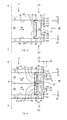
figure 3 represents on a larger scale a cross-sectional view, indicated by III-III infigure 1 , through a border of a first embodiment of a glazing panel according to the invention,; -
figure 4 represents in a way similar tofigure 3 a cross-sectional view through the border of another embodiment of a glazing panel in accordance with the present invention; -
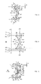
figure 5 is a cross-sectional view on a spacer frame structure of still another preferred embodiment of a glazing panel in accordance with the present invention; -
figures 6 and 7 represent cross-sectional views similar tofigure 3 , through a glazing panel wherein the spacer frame structure offigure 5 is applied, in full line when the glazing panel is not subjected to external load, and in dash line after deformation of the glazing panel under a certain load; -
figures 8 and 9 , are similar views asfigures 5 and 6 for still another embodiment of a spacer frame structure and the corresponding glazing panel in accordance with the invention respectively; -
figure 10 is another alternative for the spacer frame structure represented infigure 5 ; -
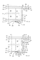
figures 11 and 12 are views similar tofigure 6 of a cross-section through still two other embodiments of a glazing panel in accordance with the invention; -
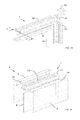
figure 13 is a perspective view of the embodiment of a spacer frame structure represented infigure 5 , in a disassembled status; and, -
figure 14 is a perspective view of a glazing panel according to the invention represented infigures 6 and 7 , which is partly assembled and which comprises the spacer frame structure offigure 13 . - The
assembly 1 of glazing panels according to the invention represented infigure 1 comprises fourglazing panels 2 according to the invention and is an application wherein theglazing panels 2 are used for realizing a window in anopening 3 of abuilding 4. - As is clearly illustrated in
figures 3 and 4 for example, such aglazing panel 2 according to the invention comprises two parallelouter glazing panes spacer frame structure 7. - Possibly, a
glazing panel 2 in accordance with the invention has additionallyintermediate glazing panes 8 or intermediate transparent panes made of a synthetic material. - In the window application of
figure 1 , three glazing panels,i.e. glazing panels remaining glazing panel 12 is a glazing panel that can be opened and closed. -
Glazing panel 12 is therefore hinge mounted by means ofhinges 13 on the adjacent fixedglazing panel 10, while it is supported in the closed status againstlocking points 14 at aborder 15 of the otheradjacent glazing panel 11. - Other hardware provided at the hinged
glazing panel 12 consists in awindow handle 16. - Neighbouring fixed
glazing panels 9 and 10 are interconnected at discrete positions which are distant from one another by means ofcoupling elements 17, which are directly attached to thespacer frame structures 7 of theconcerned glazing panels 9 and 10. - The
complete assembly 1 ofglazing panels 2 is in this case surrounded by aframework 18, which is mounted in theopening 3 between theassembly 1 ofglazing panels 2 and thebuilding 4, each of theglazing panels framework 18 by means ofsimilar coupling elements 19 at discrete positions which are distant from one another. - The
framework 18 itself is fixed in thebuilding structure 4 by means ofanchors 20, such asconcrete anchors 20 or the like. - The
framework 18 is however nothing like a window frame known according to the state of the art for supporting and bearing a known glazing pane. - Indeed, the mutual interconnection between the
glazing panels 9 and 10 as well as the interconnection of theglazing panels framework 18 is exclusively realised by thecoupling elements spacer frame structure 7 of theglazing panels 2. - Similarly, the hardware consisting of
hinges 13,locking points 14 and thewindow handle 16 are also directly and exclusively mounted on the concernedspacer frame structures 7 for supporting and bearing the hingedglazing panel 12 in the neighbouringglazing panels assembly 1. - According to the invention, the
spacer frame structure 7 and the bond of thisspacer frame structure 7 with theouter glazing panes intermediate panes 8 is designed in such a way that theglazing panels 2 have enough structural strength in order to withstand the loads, such as the load due to the weight of theglazing panes outer glazing panes - The
framework 18 can therefore be a very lightweight frame which has no particular structural strength and must be considered in this case as a simple aid for installing theassembly 1 ofglazing panes 2 into theopening 3 in thebuilding 4, which opening 3 can for example be anopening 3 of anunfinished building 4 having edges with a lot of irregularities. - The
glazing panels 9 and 12 in accordance with the invention are essentially only bearing their own weight and loads on their own surface and are for this reason indicated as being self-supportingglazing panels 9 and 12. - On the contrary,
glazing panel 10 is bearing at oneedge 21adjacent glazing panel 12 by means ofhinges 13 and will be indicated as being a load bearingglazing panel 12, whereasglazing panel 11 is only partly bearing load from the neighbouring hingedglazing panel 12 and is therefore indicated as being a semi-load bearingglazing panel 11. -
Figure 2 illustrates anotherassembly 1 ofglazing panels 2 according to the invention, this time in avertical curtain wall 22 application, wherein noframework 18 is used at all,adjacent glazing panels 2 being interconnected at theirvertical edges 23 by means ofelongated coupling elements 24 which act again directly on the correspondingspacer frame structures 7 of theconcerned glazing panels 22. - As in the preceding example, the
glazing panels 22 have according to the invention again a sufficient intrinsic structural strength and load bearing capacity to withstand the loads on thecurtain wall 22. - In general, it is interesting when in
assembly 1 according to theinvention glazing panels 2 of theassembly 1 are mutually coupled or thatglazing panels 2 of theassembly 2 are coupled to aframework 18, abuilding structure 4 or the like by means of onemore coupling elements spacer frame structure 7 of theconcerned glazing panels 2 and which prevent a movement of theglazing panel 2 in a direction AA' perpendicular to theglazing panes glazing panels 2 due to temperature change. -
Figure 3 is a cross-sectional view through a first embodiment of aglazing panel 2 according to invention, which has all the basic characteristics necessary in order to obtain the aforementioned structural strength of theglazing panel 2. - Each
outer glazing pane glazing pane surfaces - On the one hand, a pair of outside glazing pane surfaces 25 of the
glazing panes glazing panel 2, the outer glazing pane surfaces 25 being in contact with the outer environment. - On the other hand, a pair of inside glazing pane surfaces 26 of the
glazing panes glazing panel 2. - These inside glazing pane surfaces 26 together with an inward directed
side 27 of thespacer frame structure 7 delimit at least oneinner cavity 28, thiscavity 28 being of course very important for the thermal insulation characteristics of theglazing panel 2. - In the embodiment represented in
figure 3 , the inside glazing pane surfaces 26 are bonded glazing pane surfaces 26, since they are each bonded to one of thelateral sides 29 of thespacer frame structure 7. - According to the present invention, said
lateral sides 29 of thespacer frame structure 7 are furthermore provided with aprotrusion 30, which supports the corresponding bondedglazing pane surface 29. - Additionally, adjacent to each protrusion 30 a
slot 31 is left between the concernedlateral side 29 of thespacer frame structure 7 and the concerned bondedglazing pane surface 26. - Each
slot 31 extends in this case from the correspondingprotrusion 29 to anouter border 32 of the adjacent bondedglazing pane surface 26, as well as to anouter border 33 of the adjacentlateral side 29 of thespacer frame structure 7. - Actually, the
spacer frame structure 7 has anouter border 33 surrounding theglazing panel 2 and which fits within theouter border 32 of bothouter glazing panes - In the embodiment represented in
figure 3 , theslots 31 are completely filled with anadhesive material 34. - However, embodiments of
glazing panels 2 wherein theslots 31 are only partly filled with anadhesive material 34 are not excluded from the invention. - The bonded glazing pane surfaces 26 are bonded to the corresponding
lateral side 29 of thespacer frame structure 7 in a region in the vicinity of their circumference orouter border 32. - In the case of
figure 3 the bonded glazing pane surfaces 26 are supported on a correspondingprotrusion 30 of thespacer frame structure 7 at an inward area of said region, which inward area is at some distance from the adjacentouter border 32 of the concerned bondedglazing pane surface 26. - The
spacer frame structure 7 is in this embodiment also composed of asingle spacer frame 35 and can be fabricated of a metal such as aluminum, steel or whatever other metal. - As an alternative it is also possible and even preferable that spacer frames 35 of a
glazing panel 2 in accordance with the invention are fabricated from glass-fiber reinforced polyester or glass-fiber reinforced polyurethane. - The
protrusions 30 extend somewhat inwardly in the direction of thecavity 28, so that aninward groove 36 is formed at theinward side 27 of thespacer frame 35. - The
spacer frame structure 7 or, what is the same in this case, thespacer frame 35 is provided with attachment means 37 which consists in a longitudinaloutward groove 37 provided in itsouter circumference 38. - This
outward groove 37 has at both lateral sides 29 a longitudinal hook-shapededge 39, each hook-shaped edge having an inward extendinghook 40 which is directed towards thehook 40 of the other hook-shapededge 39 at the oppositelateral side 29 of thegroove 37. - The attachment means or groove 37 is intended for coupling or attaching elements directly to the
spacer frame structure 7, such as thecoupling elements figures 1 and 2 , for interconnectingglazing panels 2 or for connecting aglazing panel 2 to aframework 18 or to another outer structure. - Also hardware, such as hinges 13, locking points 14 or window handles 16 and so on can be connected directly to the
spacer frame structure 7 by using the coupling means 37. - The
inward side 27 of thespacer frame 35 adjacent to thecavity 28 in theglazing panel 2 is covered by a vapor-tight foil 41 which extends between theouter glazing panes hermetic layer 41 between thoseouter glazing panes - Preferably and as is the case in embodiment of
figure 3 , this vapor-tight foil 41 is also extending between eachouter glazing pane protrusion 30 at each of thelateral sides 29 of thespacer frame structure 7. - The vapor-
tight foil 41 can be ametal foil 41 made of stainless steel or aluminum. - As an alternative, the vapor-
tight foil 41 can for example also be an aluminum metalizedmulti-polymeric layer foil 41, such as an aluminum metalized polyethylene terephthalate foil (PET-foil) or an aluminum metalized ethylene vinyl alcohol foil (EVOH-foil), while the use of still other materials for realizing ahermetic cover 41 are not excluded from the present invention. - The
adhesive material 34 in theslots 31 forms an adhesive binding layer and preferably consists of a semi-stiff material with a shear strength of between 2 and 9 N/mm2 and a hardness of between 65 and 90 shore A. - It is also possible according to the invention to provide the same or another adhesive material between an
outer glazing pane protrusion 30 of thespacer frame structure 7, for example on top of the vapor-tight foil 41, at both sides of the vapor-tight foil 41 or an adhesive material by which theprotrusion 30 is bonded directly to theouter glazing pane tight foil 41 is applied at that position. - In the embodiment represented in
figure 3 , theprotrusions 30 have a certain height H compared to an adjacent part on the concernedlateral side 29 of thespacer frame structure 7 and theslots 31 have a width W which corresponds to the height H of theconcerned protrusion 30, at least with exception of a very small difference due to the presence of the vapor-tight foil 41 and a possible very thin adhesive layer between theprotrusions 29 and theouter glazing panes - It is however not excluded according to the invention to design a
glazing panel 2 wherein theslots 31 have a completely different cross-sectional shape and possibly less regular shape. - In any case, it is interesting according to the invention that the
protrusions 30 on the lateral sides 29 of thespacer frame structure 7 are a kind of laterally outwards directed pivoting surfaces around which theouter glazing panes slots 31 are such that theouter border 32 of theglazing pane lateral side 29 so to limit stress in theglazing panel 2 under load. - In that way a
glazing panel 2 in accordance with the present invention can have a very high structural strength. Although this is not required according to the invention, aglazing panel 2 in accordance with the invention will be typical a rectangular self-supportingglazing panel 2 having a length L of for example typically 2,5 m and a width B of for example typically 1,2 m, while other dimensions and shapes are not excluded. - According to a preferred embodiment of a
glazing panel 2 in accordance with the present invention theglazing panel 2 has a load bearing capacity which is such that the maximum deformation of theglazing panel 2 under a wind load of 1600 Pa applied in a direction AA' perpendicular to the outer glazing pane surfaces 25 or 26 is less than 1/200, preferable less than 1/300 and still more preferable less than 1/500 of its length L when theglazing panel 2 is clamped at one side along its width B. - In order to avoid condensation in the
cavity 28 between theouter glazing panes desiccant 42 is preferably provided within theinward groove 36. -
Figure 4 represents still another embodiment of aglazing panel 2 in accordance with the present invention, wherein this time thespacer frame structure 7 is an assembly of two spacer frames 35, anintermediate pane 8 being provided between the pair of neighboring spacer frames 35, whichintermediate pane 8 is bonded to the correspondinglateral sides 29 of these spacer frames 35 by means of anadhesive material 34. - The other
lateral sides 29 of the spacer frames are bonded to the concernedouter glazing pane adhesive material 34. - The
glazing pane 2 of this embodiment comprises twocavities 28, respectively acavity 28 between theintermediate pane 8 and the firstouter glazing pane 5 and a cavity between theintermediate pane 8 and the otherouter glazing pane 6. - The
spacer frame structure 7 comprises tubular parts formed by the tubular shaped spacer frames 35. - Furthermore, each
spacer frame 35 of thespacer frame structure 7 has mainly the same outer shape as thespacer frame 35 represented infigure 3 , with at both lateral sides 29 aprotrusion 30 andadjacent slot 31 and with aninward groove 36 at the inward directedside 27 which is covered by a vapor-tight foil 41 provided between theintermediate pane 8 and the concernedouter glazing pane desiccant 42 applied in thegroove 36. - Another difference with the preceding embodiment of a
glazing panel 2 in accordance with the invention is that the attachment means 37 of thespacer frame structure 7 has the same shape of anouter groove 37 as in the preceding case, but thegroove 37 is this time formed by the combination of two hook shapededges 39 withhook 40 provided each provided at one of the lateral sides of thespacer frame structure 7 on theconcerned spacer frame 35. Still another difference is that the attachment means 37 formed by the hook shapededges 39 extend with their height D above theouter borders 32 of the adjacent bonded glazing pane surfaces 26, while the main body of thespacer frame structure 7 still fits within theouter border 32 of bothouter glazing panes - In the embodiment of a
glazing panel 2 in accordance to the invention represented infigure 4 there is just oneintermediate pane 8. - Nevertheless, according to the invention it embodiments with multiple intermediate panes in an assembly of multiple spacer frames 35 wherein each
intermediate pane 8 is provided between each pair of neighboring spacer frames 35, are not excluded from the invention. -
Figures 6 to 7 illustrate another preferred embodiment of aglazing panel 2 wherein anotherspacer frame structure 7, illustrated infigure 5 , is used. - This embodiment of a
glazing panel 2 in accordance with the invention has aspacer frame structure 7 which does not comprise tubular parts and is essentially formed by thin wall plate likeparts 43, so that thespacer frame structure 7 is a rather slim structure. - Apart from being thin wall plated the
spacer frame structure 7 has a shape which is mainly the same as in the preceding cases, since it is again provided at bothlateral sides 29 with aprotrusion 30 having a height H with respect to the remaining part of thelateral sides 29 for supportingouter glazing panes - The
spacer frame structure 7 has an essentially U-shaped cross-section formed by a bottom 44 and twoupright flanks 45, eachflank 45 having anoutward side 29 which is alateral side 29 of thespacer frame structure 7 and an inward side provided with ahook 40 for forming a hook shapededge 39, intended for being attachment means 37 shaped as agroove 37 as in the preceding cases. - The
protrusions 30 on the outwardlateral side 29 extend somewhat sideward with respect to the side of thespacer frame structure 27 which is formed by the bottom 44 and whichside 27 is intended to be directed inwards towards acavity 28 in aglazing panel 2. - In that way, again a
groove 36 at the inward directedside 27 is formed. - A difference with the preceding cases is that the spacer frame structure comprises an
intermediate part 44 formed in this case by the bottom 44 and by which the lateral sides 29 of the spacer frame structure are connected to one another. - This
intermediate structure 44 is provided with acrumple zone 46 for a lateral movement of thelateral sides 29 of thespacer frame structure 7 towards one another or away from one another. - The
crumple zone 46 consists ofparts 46 of the intermediate structure or bottom 44 which are oriented under a certain angle E with respect to the lateral direction AA' perpendicular to the lateral sides 29 orouter glazing panes - Another characteristic of the
crumple zone 46 in the case represented in thefigures 5 to 7 , is that acentral part 47 of the bottom 44 of thespacer frame structure 7 is somewhat offset with respect to theouter parts 48 near theflanks 45 of thespacer frame structure 7 in a direction towards thehooks 40. - The central offset
part 47 provides at the inward directedside 27 of the spacer frame structure 7 a recess or groove which can serve as a support for anintermediate panel 8. - In general terms, the
crumple zone 46 is a zone of thespacer frame structure 7 which facilitates somewhat a deformation of thespacer frame structure 7 by having some weaker parts compared to a full straight shape, mainly for allowing a movement of theouter glazing panes figure 6 , but also for allowing a deformation corresponding with a certain bending of theouter glazing panes figure 7 . - As in the preceding embodiments of a
glazing panel 2 according to the invention, theslots 31 provided adjacent to theprotrusions 30 between theouter glazing panes lateral side 29 of thespacer frame structure 7, provide the necessary space for allowing such a bending movement of theouter glazing panes -
Figures 8 and 9 illustrate anotherspacer frame structure 7 andglazing panel 2 equipped with such a spacer frame structure according to the invention, which hasouter flanks 45 completely similar to theflanks 45 of the preceding embodiment illustrated in thefigures 5 to 7 . - The difference with the preceding embodiments however is contained in the
intermediate part 44 which has this time a buckling shape, the bottom 44 having twoparts 49 which are inclined under an angle E with respect to the lateral sides 29 towards thecenter 47 of the bottom, so to form thecrumple zone 46 of thespacer frame structure 7. - The buckling
shape 47 provides the required flexibility for allowing a movement in the lateral direction AA', as is illustrate in dash line infigure 9 . -
Figure 10 represents an alternative for thespacer frame structure 7 offigure 5 , wherein in between theouter flanks 45 an additionalintermediate flank 50 is provided forming an additional hook shapededge 39 which serves as a part of attachment means 37 with an adapted shape forcoupling elements hinges 13, locking points 14 window handles 16 and so on. - In the preceding cases the
glazing panel 2 had always a symmetric shape with respect to a central plane parallel to theouter glazing panes spacer structure 7 according tofigure 10 . - The
spacer frame structure 7 offigure 10 is made of glass-fiber reinforced polyester or glass-fiber reinforced polyurethane, thereinforcement 51 being indicated in the figure with a dash line. - It is clear that all kinds of
spacer frame structures 7 with other dimensions and other shapes are not excluded from the invention. -
Figures 11 and 12 illustrate stillother glazing panels 2 wherein theouter glazing panes outer glazing pane 6 being somewhat smaller thanouter glazing pane 5 and theirouter borders 32 being somewhat offset with respect to one another. - An
intermediate pane 8 has the same size as the smallest outglazing pane 6 and thedifferent panes traditional spacer 52 known according to the state of the art. - Additionally, also a
spacer frame structure 7 keeps theouter glazing panes glazing panel 2 as in the preceding cases. - The
spacer frame structure 7 in these figures has a specially adapted shape with a cross-section having an essentially Z-shaped form, theouter flank 45 adjacent to the biggestouter glazing pane 5 extending in the outward direction with respect to the bottom 44 of thespacer frame structure 7, while theouter flank 45 adjactent to the smallestouter glazing pane 6 extends inwards with respect to the bottom 44. - The
outer flanks 45 have again the same characteristics, i.e. aprotrusion 30 at the lateral sides 29 of the spacer frame structure 7 aslot 31 being left between the concernedlateral side 29 and the correspondingouter glazing pane - Another difference however with the preceding embodiments of
glazing panel 2 in accordance with the invention is that one of the bonded glazing pane surfaces, i.e.glazing pane surface 26 by which the biggestouter glazing pane 5 is bonded to thespacer frame structure 7, is an insideglazing pane surface 26 adjacent to acavity 28 of theglazing panel 2, while the other bonded glazing pane surfaces, i.e.glazing pane surface 25 by which the smallestouter glazing pane 6 is bonded to thespacer frame structure 7, is an outsideglazing pane surface 25. - The bonded glazing pane surfaces 25 and 16 are both again as in the preceding embodiments bonded to the corresponding
lateral side 29 of thespacer frame structure 7 in a region in the vicinity of their circumference orouter border 32. - The bonded
glazing pane surface 25 of the smallestouter glazing pane 6 is however supported on aprotrusion 30 of thespacer frame structure 7 at anoutward area 53 of said region, which outward area extends unto theouter border 32 of the concerned bondedglazing pane surface 25. - The
intermediate part 44 of the spacer frame structure illustrated infigure 11 is completely flat and is directed perpendicularly to theouter glazing panes - The
intermediate part 44 is made of a thin wall plate so that a bending deformation is not restricted too much and stresses due to such a deformation are kept within acceptable limits. - An
adhesive material 34 is applied in theslots 31 and is also flexible enough to allow the aforementioned bending deformation of the adjacentouter glazing pane figure 11 . - The embodiment of a
glazing panel 2 according to the invention represented infigure 12 is quite similar, but has all kinds of hook shapededges 39 formed byouter flanks 45 andintermediate flank 50, acrumple zone 46 being also provided in the form of acentral part 47 of the bottom 44 which is offset with respect to the outer parts for the bottom. - Apart from a similar flexibility for bending deformations as in the case of
figure 11 , thespacer frame structure 7 in theglazing panel 2 offigure 12 has also a rather limited rigidity against forces applied in the lateral direction, so that also a lateral flexibility is present in this embodiment offigure 12 , allowing small lateral movements of theouter glazing panes figure 12 by means of dash lines. - As in the preceding embodiments the
spacer frame structure 7 has in the examples offigures 11 and 12 anouter border 33 which fits within theouter border 32 of theouter glazing pane 5 with the largest dimensions. -
Figures 13 and 14 illustrate in perspective view how aspacer frame structure 7 as well as aglazing panel 2 according to the invention are assembled. - In order to realize a
rectangular glazing panel 2, thestructural spacer frame 7 consists ofrectilinear parts 54 which are connected to one another in corners by means ofinserts 55 which are slid in thegroove 37 forming the attachment means 37 and which are further bonded by means of anadhesive material 34 to therectilinear parts 54. - The present invention is by no means limited to
glazing panels 2 orassemblies 1 ofsuch glazing panels 2 according to the invention described as examples and illustrated in the drawings, butsuch glazing panels 2 orassemblies 1 ofsuch glazing panels 2 according to the invention can be realised in all kinds of variants, without departing from the scope of the invention.
Claims (15)
- Glazing panel (2) comprising at least two parallel outer glazing panes (5,6) spaced apart from one another by means of a spacer frame structure (7), one glazing pane surface (25,26) of each outer glazing pane being a bonded glazing pane surface (25,26) which is bonded to a lateral side (29) of the spacer frame structure (7), characterized in that said lateral sides (29) of the spacer frame structure (7) are provided with a protrusion (30) which supports the corresponding bonded glazing pane surface (25,26), a slot (31) being left adjacent to the protrusion (30) between the concerned lateral side (29) of the spacer frame structure (7) and the concerned bonded glazing pane surface (25,26), the slot (31) being at least partly filled with an adhesive material (34).
- Glazing panel (2) according to claim 1, characterized in that at least one of the slots (31) is extending from the protrusion (30) to an outer border (32) of the adjacent bonded glazing pane surface (25,26) or of the adjacent lateral side (33) of the spacer frame structure (7).
- Glazing panel (2) according to any of the preceding claims, characterized in that it is a self-supporting glazing panel (2), having sufficient structural strength for bearing at least the weight of the glazing panes (5,6,8) of the glazing panel (2) as well as for supporting a wind load of 1600 Pa applied in a direction (AA') perpendicular to a surface (25,26) of one of the outer glazing panes (5,6), without the need of an outer supporting sash frame for supporting the glazing panel (2).
- Glazing panel (2) according to any of the preceding claims, characterized in that both bonded glazing pane surfaces (25,26) are inside glazing pane surfaces (26) adjacent to a cavity (28) of the glazing panel (2).
- Glazing panel (2) according to any of the preceding claims, characterized in that one of the bonded glazing pane surfaces (25,26) is an inside glazing pane surface (26) adjacent to a cavity (28) of the glazing panel (2) and the other is an outside glazing pane surface (25).
- Glazing panel (2) according to any of the preceding claims, characterized in that the spacer frame structure (7) has an outer border (33) which fits within the outer border (32) of the outer glazing pane (5) with the largest dimensions.
- Glazing panel (2) according to any of the preceding claims, characterized in that the spacer frame structure (7) does not comprise tubular parts (35) and is essentially formed by thin wall plate like parts.
- Glazing panel (2) according to any of the preceding claims, characterized in that the spacer frame structure (7) comprises an intermediate part (44) by which the lateral sides (29) of the spacer frame structure (7) are connected to one another which intermediate part (44) is provided with a crumple zone (46) for a lateral movement of the lateral sides (29) of the spacer frame structure (7) towards one another or away from one another.
- Glazing panel (2) according to claim 8, characterized in that the crumple zone (46) consists of parts (46) of the intermediate structure which are oriented under a certain angle (E) with respect to the lateral direction (AA') perpendicular to the outer glazing panes (5,6).
- Glazing panel (2) according to any of the preceding claims, characterized in that spacer frames (35) of the glazing panel (2) are fabricated from glass-fiber reinforced polyester or glass-fiber reinforced polyurethane.
- Glazing panel (2) according to any of the preceding claims, characterized in that the spacer frame structure (7) is provided with attachment means (37) which consists of a longitudinal groove (37) provided in its outer circumference (38), the groove (37) having at both lateral sides (29) a longitudinal hook-shaped edge (39), each hook-shaped edge (39) having an inward extending hook (40) which is directed towards the hook (4a) of the other hook-shaped edge (39) at the opposite lateral side (29) of the groove (37).
- Glazing panel (2) according to any of the preceding claims, characterized in that an inward side (27) of spacer frames (35) of the spacer structure (7) adjacent to a corresponding cavity (28) in the glazing panel (2) is covered by a vapor-tight foil (41) which extends between panes (5,6,8) adjacent to the concerned spacer frame (35) for forming a hermetic layer (41) between those panes (5,6,8).
- Glazing panel (2) according to claim 12, characterized in that the vapor-tight foil (41) is extending between an outer glazing pane (5,6) and an abovementioned protrusion (30) on a lateral side (29) of the spacer frame structure (7).
- Glazing panel (2) according to any of the preceding claims, characterized in that an adhesive material (34) is provided between an outer glazing pane (5,6) and a protrusion (30) of the spacer frame structure (7).
- Assembly (1) of a multitude of glazing panels (2) according to any of the preceding claims, characterized in that adjacent glazing panels (2) are connected to one another by connecting spacer structure frames (7) of adjacent glazing panels (2), in order to form an assembly (1) which behaves as a single, self-supporting structural glazing panel (2) and this without the need of enclosing the outer borders (32) of the glazing panels (2) in an additional outer supporting frame.
Priority Applications (3)
| Application Number | Priority Date | Filing Date | Title |
|---|---|---|---|
| EP12174240.7A EP2679758A1 (en) | 2012-06-28 | 2012-06-28 | Glazing panel and assembly of a multitude of such glazing panels |
| EP13732176.6A EP2867429B1 (en) | 2012-06-28 | 2013-06-28 | Glazing panel and assembly of a multitude of such glazing panels |
| PCT/EP2013/063632 WO2014001503A1 (en) | 2012-06-28 | 2013-06-28 | Glazing panel and assembly of a multitude of such glazing panels |
Applications Claiming Priority (1)
| Application Number | Priority Date | Filing Date | Title |
|---|---|---|---|
| EP12174240.7A EP2679758A1 (en) | 2012-06-28 | 2012-06-28 | Glazing panel and assembly of a multitude of such glazing panels |
Related Child Applications (1)
| Application Number | Title | Priority Date | Filing Date |
|---|---|---|---|
| EP12189757.3 Division-Into | 2012-10-24 |
Publications (1)
| Publication Number | Publication Date |
|---|---|
| EP2679758A1 true EP2679758A1 (en) | 2014-01-01 |
Family
ID=48700597
Family Applications (2)
| Application Number | Title | Priority Date | Filing Date |
|---|---|---|---|
| EP12174240.7A Withdrawn EP2679758A1 (en) | 2012-06-28 | 2012-06-28 | Glazing panel and assembly of a multitude of such glazing panels |
| EP13732176.6A Not-in-force EP2867429B1 (en) | 2012-06-28 | 2013-06-28 | Glazing panel and assembly of a multitude of such glazing panels |
Family Applications After (1)
| Application Number | Title | Priority Date | Filing Date |
|---|---|---|---|
| EP13732176.6A Not-in-force EP2867429B1 (en) | 2012-06-28 | 2013-06-28 | Glazing panel and assembly of a multitude of such glazing panels |
Country Status (2)
| Country | Link |
|---|---|
| EP (2) | EP2679758A1 (en) |
| WO (1) | WO2014001503A1 (en) |
Cited By (3)
| Publication number | Priority date | Publication date | Assignee | Title |
|---|---|---|---|---|
| TWI666376B (en) * | 2016-09-23 | 2019-07-21 | 比利時商Agc歐洲玻璃公司 | Reinforced insulating glass unit |
| EP3643869A1 (en) * | 2018-10-22 | 2020-04-29 | Technoform Glass Insulation Holding GmbH | Spacer for an insulating glazing unit preventing thermal stress |
| US20210388666A1 (en) * | 2018-10-30 | 2021-12-16 | Universita' Degli Studi Di Milano - Bicocca | Insulating glazing with luminescent solar concentrator for production of electrical energy |
Citations (8)
| Publication number | Priority date | Publication date | Assignee | Title |
|---|---|---|---|---|
| US5512341A (en) * | 1992-05-18 | 1996-04-30 | Crane Plastics Company Limited Partnership | Metal-polymer composite insulative spacer for glass members and insulative window containing same |
| WO1999014169A1 (en) * | 1997-09-15 | 1999-03-25 | Andersen Corporation | A unitary insulated glass unit and method of manufacture |
| WO2001088319A1 (en) * | 2000-05-13 | 2001-11-22 | Bayer Isolierglas- Und Maschinentechnik Gmbh | Insulating glass pane with individual plates and a spacer profile |
| DE20216560U1 (en) * | 2002-10-25 | 2002-12-19 | Erbslöh Aluminium GmbH, 42553 Velbert | Spacers for panes of multiple insulating glasses |
| US6829861B1 (en) * | 2002-08-15 | 2004-12-14 | Atwood Mobile Products, Inc. | Awning-type insulated glazing assembly |
| DE102010015612A1 (en) * | 2010-04-19 | 2011-10-20 | Inoutic / Deceuninck Gmbh | Window assembly, has glass panes adhered with wing frame and arranged parallel and at distance from each other, where frame has flexible laths for adhering with glass panes, and laths extend perpendicular to longitudinal axis of frame body |
| US20120151857A1 (en) * | 2010-12-17 | 2012-06-21 | Infinite Edge Technologies, Llc | Triple pane window spacer, window assembly and methods for manufacturing same |
| EP2476852A2 (en) * | 2011-01-14 | 2012-07-18 | GEZE GmbH | Assembly aid for a leaf of a door, window or the like |
-
2012
- 2012-06-28 EP EP12174240.7A patent/EP2679758A1/en not_active Withdrawn
-
2013
- 2013-06-28 EP EP13732176.6A patent/EP2867429B1/en not_active Not-in-force
- 2013-06-28 WO PCT/EP2013/063632 patent/WO2014001503A1/en not_active Ceased
Patent Citations (8)
| Publication number | Priority date | Publication date | Assignee | Title |
|---|---|---|---|---|
| US5512341A (en) * | 1992-05-18 | 1996-04-30 | Crane Plastics Company Limited Partnership | Metal-polymer composite insulative spacer for glass members and insulative window containing same |
| WO1999014169A1 (en) * | 1997-09-15 | 1999-03-25 | Andersen Corporation | A unitary insulated glass unit and method of manufacture |
| WO2001088319A1 (en) * | 2000-05-13 | 2001-11-22 | Bayer Isolierglas- Und Maschinentechnik Gmbh | Insulating glass pane with individual plates and a spacer profile |
| US6829861B1 (en) * | 2002-08-15 | 2004-12-14 | Atwood Mobile Products, Inc. | Awning-type insulated glazing assembly |
| DE20216560U1 (en) * | 2002-10-25 | 2002-12-19 | Erbslöh Aluminium GmbH, 42553 Velbert | Spacers for panes of multiple insulating glasses |
| DE102010015612A1 (en) * | 2010-04-19 | 2011-10-20 | Inoutic / Deceuninck Gmbh | Window assembly, has glass panes adhered with wing frame and arranged parallel and at distance from each other, where frame has flexible laths for adhering with glass panes, and laths extend perpendicular to longitudinal axis of frame body |
| US20120151857A1 (en) * | 2010-12-17 | 2012-06-21 | Infinite Edge Technologies, Llc | Triple pane window spacer, window assembly and methods for manufacturing same |
| EP2476852A2 (en) * | 2011-01-14 | 2012-07-18 | GEZE GmbH | Assembly aid for a leaf of a door, window or the like |
Cited By (5)
| Publication number | Priority date | Publication date | Assignee | Title |
|---|---|---|---|---|
| TWI666376B (en) * | 2016-09-23 | 2019-07-21 | 比利時商Agc歐洲玻璃公司 | Reinforced insulating glass unit |
| EP3643869A1 (en) * | 2018-10-22 | 2020-04-29 | Technoform Glass Insulation Holding GmbH | Spacer for an insulating glazing unit preventing thermal stress |
| WO2020083777A1 (en) * | 2018-10-22 | 2020-04-30 | Technoform Glass Insulation Holding Gmbh | Climate stress compensating spacer |
| US12331584B2 (en) | 2018-10-22 | 2025-06-17 | Technoform Glass Insulation Holding Gmbh | Climate stress compensating spacer |
| US20210388666A1 (en) * | 2018-10-30 | 2021-12-16 | Universita' Degli Studi Di Milano - Bicocca | Insulating glazing with luminescent solar concentrator for production of electrical energy |
Also Published As
| Publication number | Publication date |
|---|---|
| EP2867429A1 (en) | 2015-05-06 |
| EP2867429B1 (en) | 2020-09-30 |
| WO2014001503A1 (en) | 2014-01-03 |
Similar Documents
| Publication | Publication Date | Title |
|---|---|---|
| EP2027347B1 (en) | A translucent panel | |
| EP3342972B1 (en) | A window having a sash and an improved connection to the hinge | |
| EP3348737A1 (en) | Roof window particularly for flat roofs | |
| JPH05141152A (en) | Structure of mounting-section for fixing glass pane | |
| EP3779085B1 (en) | A skylight window | |
| HUT67561A (en) | Frameless insulating glazing and process for producing the same | |
| EP1179112B1 (en) | Profile configuration for interrupting a heat conducting bridge between an inner side and an outer side | |
| EP2679758A1 (en) | Glazing panel and assembly of a multitude of such glazing panels | |
| EP3783163B1 (en) | A skylight window | |
| EP1600596B1 (en) | Point-Supported Glazed Cladding System | |
| JP6971930B2 (en) | Skylight window frame, skylight | |
| EP3779090B1 (en) | A skylight window | |
| EP3748101B1 (en) | Building exterior panel and assembly structure thereof | |
| EP3779089B1 (en) | A skylight window frame for being installed in or on a roof of a building, a system comprising a skylight window and a method for fastening a skylight window frame | |
| JP5396058B2 (en) | Glass support structure | |
| JP7356945B2 (en) | skylight window frame, skylight | |
| EP3779086B1 (en) | A skylight window | |
| EP2636811B1 (en) | A skylight comprising multilayer panes and a connection system | |
| KR101060088B1 (en) | Double glazing exterior wall structure of building structure | |
| EP3779091B1 (en) | A skylight window | |
| EP3783164B1 (en) | A skylight window | |
| KR102727864B1 (en) | Double-glazed windows with excellent drainage and insulation performance | |
| EP4617467A1 (en) | Roof window comprising vacuum insulated glass unit with projecting glass sheet portion at roof window side | |
| CN116838035B (en) | A skylight structure that can be rotated and opened from all four sides. | |
| CN218337289U (en) | A stringer for greenhouse |
Legal Events
| Date | Code | Title | Description |
|---|---|---|---|
| PUAI | Public reference made under article 153(3) epc to a published international application that has entered the european phase |
Free format text: ORIGINAL CODE: 0009012 |
|
| AK | Designated contracting states |
Kind code of ref document: A1 Designated state(s): AL AT BE BG CH CY CZ DE DK EE ES FI FR GB GR HR HU IE IS IT LI LT LU LV MC MK MT NL NO PL PT RO RS SE SI SK SM TR |
|
| AX | Request for extension of the european patent |
Extension state: BA ME |
|
| STAA | Information on the status of an ep patent application or granted ep patent |
Free format text: STATUS: THE APPLICATION IS DEEMED TO BE WITHDRAWN |
|
| 18D | Application deemed to be withdrawn |
Effective date: 20140702 |