EP1600596B1 - Point-Supported Glazed Cladding System - Google Patents
Point-Supported Glazed Cladding System Download PDFInfo
- Publication number
- EP1600596B1 EP1600596B1 EP05104363A EP05104363A EP1600596B1 EP 1600596 B1 EP1600596 B1 EP 1600596B1 EP 05104363 A EP05104363 A EP 05104363A EP 05104363 A EP05104363 A EP 05104363A EP 1600596 B1 EP1600596 B1 EP 1600596B1
- Authority
- EP
- European Patent Office
- Prior art keywords
- cladding
- slots
- supported
- pins
- point
- Prior art date
- Legal status (The legal status is an assumption and is not a legal conclusion. Google has not performed a legal analysis and makes no representation as to the accuracy of the status listed.)
- Active
Links
Images

Classifications
-
- E—FIXED CONSTRUCTIONS
- E06—DOORS, WINDOWS, SHUTTERS, OR ROLLER BLINDS IN GENERAL; LADDERS
- E06B—FIXED OR MOVABLE CLOSURES FOR OPENINGS IN BUILDINGS, VEHICLES, FENCES OR LIKE ENCLOSURES IN GENERAL, e.g. DOORS, WINDOWS, BLINDS, GATES
- E06B3/00—Window sashes, door leaves, or like elements for closing wall or like openings; Layout of fixed or moving closures, e.g. windows in wall or like openings; Features of rigidly-mounted outer frames relating to the mounting of wing frames
- E06B3/54—Fixing of glass panes or like plates
- E06B3/5427—Fixing of glass panes or like plates the panes mounted flush with the surrounding frame or with the surrounding panes
-
- E—FIXED CONSTRUCTIONS
- E06—DOORS, WINDOWS, SHUTTERS, OR ROLLER BLINDS IN GENERAL; LADDERS
- E06B—FIXED OR MOVABLE CLOSURES FOR OPENINGS IN BUILDINGS, VEHICLES, FENCES OR LIKE ENCLOSURES IN GENERAL, e.g. DOORS, WINDOWS, BLINDS, GATES
- E06B3/00—Window sashes, door leaves, or like elements for closing wall or like openings; Layout of fixed or moving closures, e.g. windows in wall or like openings; Features of rigidly-mounted outer frames relating to the mounting of wing frames
- E06B3/66—Units comprising two or more parallel glass or like panes permanently secured together
- E06B3/6604—Units comprising two or more parallel glass or like panes permanently secured together comprising false glazing bars or similar decorations between the panes
-
- E—FIXED CONSTRUCTIONS
- E06—DOORS, WINDOWS, SHUTTERS, OR ROLLER BLINDS IN GENERAL; LADDERS
- E06B—FIXED OR MOVABLE CLOSURES FOR OPENINGS IN BUILDINGS, VEHICLES, FENCES OR LIKE ENCLOSURES IN GENERAL, e.g. DOORS, WINDOWS, BLINDS, GATES
- E06B3/00—Window sashes, door leaves, or like elements for closing wall or like openings; Layout of fixed or moving closures, e.g. windows in wall or like openings; Features of rigidly-mounted outer frames relating to the mounting of wing frames
- E06B3/66—Units comprising two or more parallel glass or like panes permanently secured together
- E06B3/67—Units comprising two or more parallel glass or like panes permanently secured together characterised by additional arrangements or devices for heat or sound insulation or for controlled passage of light
- E06B3/6715—Units comprising two or more parallel glass or like panes permanently secured together characterised by additional arrangements or devices for heat or sound insulation or for controlled passage of light specially adapted for increased thermal insulation or for controlled passage of light
Definitions
- This invention relates to the field of cladding systems for buildings and similar structures, such as free-standing walls or signs, and more particularly it relates to a glazed cladding system employing panes or lites of glass.
- Glass is, in many respects, an ideal cladding material for buildings. It has an aesthetically pleasing look that is extremely durable compared to other materials, and it is maintenance free except for occasional cleaning. In its natural state, it is clear and may be tinted or coated to control appearance. It may be made fully transparent to provide a view and admit direct sunlight, or it may be made translucent or opaque via etching or coating. In the latter case it will admit diffuse light, which provides a far superior quality of natural light and helps avoid glare and localized overheating characteristic of direct beam sunlight
- the most common form for glass as building material is in flat sheets, produced by the float process.
- Such flat glass is either used in its monolithic form, or fabricated into "insulating glass units" characterized by two or more glass panes, known as lites, each lite being separated by a spacer around the perimeter.
- the most common range of thicknesses for lites of glass is 3 mm to 6 mm (1/8" to 1 ⁇ 4").
- the airspace in an insulating glass unit is on the order of 12.5 mm (0.5").
- the spacer does not provide structural rigidity and such glass units have to be attached to the building by a framing system that extends around the glass unit.
- flat glass can be challenging to use in building situations because it is relatively brittle and low in strength. It can be easily broken by application of stress.
- glass must be supported around its entire perimeter by a framing system.
- the framing system must support the glass uniformly, such that any force applied to the glass in reaction to wind load (or, in the case of sloped glass, dead load) is distributed as possible over the perimeter.
- the edge of the glass must be clamped in a manner that is free from angular constraint around an axis parallel with the perimeter in order to prevent stress concentration.
- window framing and curtainwall framing These framing systems hold the glass at the perimeter without angular constraint of edges, either by clamping the glass between elastomer seals, or by use of a structural elastomer adhesive, typically silicone.
- the framing system which is fixed to the building, must be made from linear elements that are straight and true, and these elements must be assembled so that they are in a common plane, in order that the supporting surface for the glass be flat at the time of installation.
- the linear elements that make up the framing system must also be substantial (that is, have sufficient moment of interia), in order to remain flat under load (typical specification for maximum deflection under windload is length/ 175). Therefore, the framing system must be carefully manufactured from elements that have significant structural value, especially in larger-sized window and glazing systems.
- Frameless 'point-supported' glass systems are available in today's marketplace. They hold glass via metal attachments called spiders, which are either fixed through holes drilled through the corners of the glass, or by high-performance adhesives. These systems rely on the glass itself to provide the rigidity necessary to work with point support systems. The goal of these systems is usually to achieve an elegant, highly transparent aesthetic, and they are not intended as a cost-effective clad over structure system. Because point-support systems do not support glass around the perimeter, they require increased glass thickness, compared to the glass thickness required by window and curtainwall systems which support the glass around the perimeter. Such "thick" glass typically has a thickness of 9 mm or more.
- Panels There are numerous opaque panel systems in use worldwide in the construction industry for building cladding. Common panels include metal-clad foam, metal-clad honeycomb, concrete, and stone. Opaque panels are designed to have sufficient structural strength to resist windload and other loads that may be applied to them. Depending on the system, panels are attached to buildings by a number of methods, such as framing similar to that used for glass systems (many panels can be glazed directly into curtainwall frames), or various clip systems including hook and pin.
- CPI daylighting uses multi-wall polycarbonate sheets that have inherent structural capacity sufficient to bear wind load and dead load over the scale of a single panel.
- the material is relatively low modulus, and therefore sheets have sufficient flexibility to avoid stress concentration when clipped to structural members. Sheets may be semi-transparent, translucent, or opaque. Internal structure precludes total transparency.
- Kalwall www.kalwall.com
- Kalwall is a translucent panel system, based on panels comprising two sheets of thin (1.5mm) fibre reinforced plastic, bonded to an aluminum I beam lattice structure of approximately 2.5" thickness and in plane lattice dimensions of approximately 30 cm (1') x 60 cm (2'). Kalwall panels are held in place by framing and inter-panel clamps.
- DE20304865 discloses the nearest prior art and describes a point-supported cladding system for finishing the exterior of a building using plurality of cladding units.
- Each cladding unit has a rigid spacer frame surrounded by glass, lites.
- the cladding units can be mounted to a building exterior.
- WO 02/35046 describes an optical screen element that can be used as a partition wall, glass façade, window or the like.
- the screen element has a pair of glass plates with a cell structure in-between. The cell structure permits visual access there through.
- DE 4333522 describes a cladding unit having a venting conduit for attachment to the exterior of a building.
- US 5,369,924 describes a structural curtainwall having a seal in-between. As an extra measure, it also has channels shaped to discharge water along its length into a separate channel in a rafter.
- a point-supported cladding system for finishing the exterior of a building or like structure, comprising a plurality of like rigid box-like glazed cladding units; each cladding unit comprising: a rigid spacer frame bounding said cladding unit; a pair of parallel light-transmissive glass lites having a thickness of not more than about 9 mm mounted at their periphery on said rigid spacer frame by means of a resilient seal; a plurality of first attachment elements provided at discrete attachment points on said cladding unit, and a plurality of complementary second attachment elements for mounting on structural members of said building; said first attachment elements are horizontally protruding pins adjacent each corner of said cladding unit and arranged as upper and lower pairs of pins, the pins of each of said upper and lower pairs being arranged on the right and left sides of the cladding unit respectively, the upper pair of pins being separated by a first vertical distance and the lower pair of pins being separated by a second vertical distance, said cladding unit being
- point-supported means that the cladding system is supported at discrete locations or points around its periphery as distinct from in a frame-like manner where a where member extends over a significant length along its periphery providing virtually continuous support.
- the invention is not restricted to buildings. It can be used with similar structures, such as free-standing walls or signs.
- the "Toyota portal”, as an example of "corporate architecture", would be one example of such a sign.
- a weathertight finishing material is inserted in the interstices between adjacent said cladding units of said contiguous array. It is also possible to provide a rainscreen as to be more particularly described.
- Cladding systems in accordance with the invention while using conventional thin glass, i.e. glass having a thickness of generally less than about 9 mm, and typically 3 - 6 mm, do not employ conventional window or curtainwall framing attached to the building structure. They are thus “frameless” in the sense that no frame is required on the building. They are therefore efficient and simple to install.
- the spacer frame within the cladding units is preferably made of aluminum, steel, or fiber glass, and itself has sufficient rigidity to impart structural integrity to the complete unit.
- One difficulty experienced in making such units with thin glass, which is inherently weak, is that any bond between the glass and the spacer frame must allow for thermal expansion of the glass yet at the same time provide a sufficiently effective bond for the entire unit to display structural integrity. It has been found that this can be achieved by bonding the glass lites at their periphery to the spacer frame with a resilient sealant, such as glazing silicone.
- a suitable glazing silicone for example, is made by Dow Coming Corporation.
- Embodiments of the invention provide a way to clad buildings with glass directly over structural members, trusses, or space frame support points without the need for conventional framing, thereby reducing material requirements and installed system cost.
- the invention provides a way to effectively install glass-cladding units by simply hanging panels via attachment clips. This allows a reduction in overall installation labour, versus the need to first install framing, then to lay in glass, and finally to secure the glass via pressure caps, glazing stops, or structural adhesive.
- the invention provides a way to utilize glass in combination with structural members that are subject to relatively large deflections, for example greater than L/175.
- the cladding system in accordance with an embodiment of the invention comprises an array of rectangular box-like glazed cladding units 10 mounted on structural support members 12, which typically form part of the frame of a building to be clad.
- Figure 1 shows a demonstration system in which the cladding units 10 are mounted onto a wooden frame structure in a continuous array forming a wall.
- the cladding units 10 are mounted onto the frame structure by means of a point-support attachment system to be described in more detail. Each cladding unit is supported at its corners. The lower two corners 14 support the deadweight of the cladding unit itself. The upper two corners 16 allow for upward vertical movement to accommodate thermal expansion and movement of the building itself.
- the attachment system also locks the cladding units against the structure in a direction normal to the plane of the wall that the cladding units are secured against windload.
- the glazed cladding unit in accordance with an embodiment of the invention comprises a pair of glass panes or lites separated by a rectangular aluminum spacer frame 18 defining a box-like structure.
- Glass panes or "lites" 20 having a thickness of less than 9 mm, and preferably between 3 and 6 mm, are attached at their periphery to the spacer frame 18 by means of commercial silicone glazing sealant. It is found that such a construction can be made highly rigid by using a sufficiently strong spacer frame, increasing the spacing of the glass lites, preferably to 63.5 cm (or about 2.5") for a 1219 mm x 1219 mm (48" x 48") spacer frame.
- panes up to 1.2 m x 2.4 m (4' x 8') or more, or by including a light-transmissive honeycomb insert between the panes.
- the honeycomb insert is generally made of plastic and thus has sufficient flexibility to allow for movement of the lites.
- the spacer frame provides the structural strength to the unit.
- the silicone sealer provides sufficient resilience to allow for the thermal expansion of the lites without compromising the rigidity and structural integrity of the unit.
- Angle pieces 22 are attached to the corners of the spacer frame 18, by screws or rivets, for example.
- the angle pieces 22 support attachment elements in the form of protruding stainless steel load-bearing pins 24 with enlarged heads 26.
- the pins 24 engage in slots in corresponding attachment elements mounted on the building structure.
- the lower angle pieces have shelves that extend beyond the spacer frame underneath the inner and outer lites. A block of rubber inserted between the shelves and the lites of glass acts as a setting block, transferring deadload from the weight of each lite into the angle piece and pin. In this way, long term dead loads on the silicone sealant and resultant creep of the glass relative to the spacer are avoided.
- a section of the spacer frame 18 is shown in more detail in Figures 3a and 3b .
- This is made of a generally rectangular extruded hollow aluminum section having beveled edges 28 on the inside.
- Structural members are required to support the wall system or roof system. Any structural member, including steel, aluminum, or wood sections or trusses, capable of bearing wind load and dead load, may be used as support for the cladding units in accordance with the invention.
- Figure 4 shows the bracket 30, which is attached to the structural members of the building.
- the bracket includes generally elbow or L-shaped slots 32 that receive the pins 24 of the attachment elements on the cladding units.
- Figure 5a is another view show a similar bracket 30 with slot 32.
- the brackets 30 are arranged in upper and lower pairs on opposite sides of the glazing unit 10.
- the spacing of the upper and lower pairs of brackets 30 is arranged so that the pins 24 engaging the lower pair are seated firmly in the bottom of the slots 32, whereas the pins 24 engaging the upper slots are located roughly in the middle of the slots.
- the pins have a diameter corresponding to the width of the vertical limbs of the slots 32. This arrangement ensures that the cladding units are locked against movement in a direction normal to their surface and hence the wall of the building. This is important for ensuring resistance to windload.
- the lower pair of slots 30 carries the full deadweight of the cladding unit 30.
- the upper pair of pins can move in the vertical direction to allow for expansion of the cladding units or movement of the building.
- the enlarged heads of the pins can also be located to permit lateral play, as shown in Figure 5b , so as to allow limited lateral movement of the cladding units for the same purpose.
- the elbow shaped configuration of the slots allows the panels to be applied using a conventional suction cup for handling glass by simply lifting the panels and pressing them horizontally into the horizontal entrances of the slots 32 and then sliding the units downwards, allowing the pins to drop down into the vertical portions of the slots 32 to secure the cladding units in place. Installation is therefore very quick and simple to perform.
- FIG. 6 shows four cladding units 10 mounted in place on a simulated building structure.
- Each bracket 30 has four slots lying in the same plane to accommodate pins from all adjacent upper and lower panels. As shown the bracket 30 accommodates a lower pin 24 from the upper cladding unit 10 and an upper pin 20 from the lower cladding unit 10. It also has a pair of slots to accommodate the cladding units to be installed to the right of the array shown m the drawing. For each upper and lower pair of pins, the pin on the right side is at a different level from the pin on the left side. This arrangement allows laterally adjacent cladding units to be attached to the same bracket which has four slots, one above the other without their pins colliding.
- the attachment system consists of a bracket 40 that is attached to a structural member of the building and provided with a single horizontal pin 42 facing toward the cladding units.
- a corner bracket 44 having right-angled plates 46, 48 is attached to each corner of the spacer frame of the cladding unit 10.
- the bracket 44 terminates in a hook 46, which hooks over the horizontal pin 42 of the bracket 40.
- the hooks 46 from the brackets attached to the four adjacent cladding units lie side by side on the horizontal pin 40, which is attached to the building structure.
- a T-sectioned weathertight finishing strip 50 is inserted into the interstices or gaps between the adjacent cladding units.
- This can be in the form of an extruded elastomer gasket, or it can also be cure-in-placc clastomer sealant, or a combination of the above.
- a roll-formed stainless or aluminum C-section 60 shown in Figures 11 and 12 is placed over each structural member.
- This C-section has a recessed middle portion 64, which is attached to the end of an I-section structural member forming part of a building by bolts or other suitable means.
- the bracket 30 is attached to the other side of the middle portion 64 and receives the pins 24 of the adjacent cladding units.
- the in-turned lips 68 of the C-section are provided with adhesive foam strips 70 for adherence to the backside of the backside of the cladding units.
- the adhesive foam strips serve as a backer for silicone sealant which is applied after cladding units are installed.
- this section forms an air seal and drip gutter to allow the system to function according to 'rain screen' principles.
- a deeper section should be used on rafters, and less deep section should be used on perlins, and sections should be tiled at perlin - rafter joints, so that any rainwater that penetrates the outer seal is wept away and down the rafter channels.
- a foam-backed rod 80 can be located behind the weather tight seal 50.
- Stainless steel clips may be attached to structural members on top of air seal / drip gutter section via bolts.
- the cladding units are installed by inserting pins in the front of clips and then sliding the entire unit downwards, in a 'hook and pin' arrangement.
- Bottom pins seat in the bottom of slots, and weight of the unit is transferred into the frame.
- Locking clips are installed to prevent the units from escaping via moving upward.
- Top pins are nominally positioned in the middle of the slot, so that upper pins can slide to take up differential expansion between glass, spacer, and structural members. Besides bearing weight of the units and locking this units in place, this 'hook and pin' clip system is capable of beating significant wind loads, which act normal to the glass surface.
- the pin system allows units to slide horizontally over a small distance relative to clips. This allows for differential expansion of components, as well as some small movement of structural member without buildup of stress on the glass panels or spacers.
- the hook and pin system allows relatively large deflection of structural members, by constraining only where necessary, and allowing freedom of movement everywhere else.
- the inherent structural value of the glass panel acts separately to prevent deflection of the glass edges beyond the L/175 value that is used in standard glass loading calculations.
- Glazed cladding units were fabricated that consisted of Solera® honeycomb filled translucent insulating glass units configured with 6mm glass on each side, and 'S' style aluminum spacer frame at the periphery. Separation between lites of glass was 63.5 mm (2.5"), and combination of spacer, glass, and silicone adhesive provide sufficient structural capacity to span 1200 mm (48") when only point-supported at four corners. Solera panels are manufactured by Advanced Glazings Ltd., Sydney NS Canada.
- the glass can be coated with a UV curing acrylic adhesive resin, before creating the honeycomb sandwich.
- a suitable UV curing resin can be made from a combination of acrylic monomers and oligomers, with a UV-cure catalyst, and is supplied by UCB Chemicals Ltd., Smyrna, Georgia.
- the panel is then cured by exposure to radiation from standard UV-B and UV-C fluorescent lamps through the glass.
- This honeycomb panel is very stiff and strong. Calculations show that a panel constructed in this manner of dimension 2438 mm x 1200 mm (96" x 48") is capable of supporting loads normal to its surface of up to 2441 Kg/m 2 (500 Ibs per sq.ft)., when simply supported at ends separated by the 2438mm (96") dimension. This is far in excess of standard structural capabilities of monolithic glass lites, and thus, very large areas can be spanned with only corner support.
- the above units are translucent and admit diffuse light. It is possible to make them fully transparent to provide full vision through them.
- the cladding units may consist of two layers of glass, preferably separated by a distance greater than the above 63.5 mm (2.5") thickness with an aluminum S spacer frame, but without the honeycomb core.
- the pressure in the cavity between the glass is equalized by venting to the outdoors in a controlled manner, such as by the use of a 0.5 mm (0.020") ID (inner diameter) x 30.4 mm (1.2") long stainless steel tube commonly used in the glass industry for that purpose.
- venting should be done through a dessicant cartridge to prevent buildup of humidity and resultant internal condensation within the cladding unit.
- Clear vision units with a spacing between lites in the conventional range of 12.7 mm (0.5") to 25.4mm (1") can be utilized in this system, provided that the spacer extends beyond the glass in one or more directions, forming an 'integrated spacer frame' unit.
- a standard sealed insulated glass unit can be glazed in a metal or polymer frame that provides the structural capability and compatibility with the clip system.
- the glazed cladding units in accordance with embodiments of the invention have inherent structural capacity, such that they can be secured against windload and deadload at 3 or more points only.
- the structural capacity is provided by increased spacing between lites, structural moment provided by the spacer, bonding of glass to a translucent insert in the space between the glass, and any combination of the above.
- the attachment system allow the structural cladding units to be attached directly to structural members, such that the panels are secured against windload and deadloads, but with sufficient freedom of movement to accommodate differential thermal expansion, load-induced movements, and structural movements of the building structure itself without applying damaging stress to the glazing panels.
- the weathertight finish covers the exterior of the spaces between units.
- the drip gutter system that is placed between the supporting structural members and the glass cladding units catches and weeps away any rainwater that may work its way past the outer seals, and forms an inner seal as per the rain screen principle.
Description
- This invention relates to the field of cladding systems for buildings and similar structures, such as free-standing walls or signs, and more particularly it relates to a glazed cladding system employing panes or lites of glass.
- Glass is, in many respects, an ideal cladding material for buildings. It has an aesthetically pleasing look that is extremely durable compared to other materials, and it is maintenance free except for occasional cleaning. In its natural state, it is clear and may be tinted or coated to control appearance. It may be made fully transparent to provide a view and admit direct sunlight, or it may be made translucent or opaque via etching or coating. In the latter case it will admit diffuse light, which provides a far superior quality of natural light and helps avoid glare and localized overheating characteristic of direct beam sunlight
- The most common form for glass as building material is in flat sheets, produced by the float process. Such flat glass is either used in its monolithic form, or fabricated into "insulating glass units" characterized by two or more glass panes, known as lites, each lite being separated by a spacer around the perimeter. The most common range of thicknesses for lites of glass is 3 mm to 6 mm (1/8" to ¼"). Typically, the airspace in an insulating glass unit is on the order of 12.5 mm (0.5"). The spacer does not provide structural rigidity and such glass units have to be attached to the building by a framing system that extends around the glass unit.
- Despite all its good qualities, flat glass can be challenging to use in building situations because it is relatively brittle and low in strength. It can be easily broken by application of stress. As a result, in typical applications, glass must be supported around its entire perimeter by a framing system. The framing system must support the glass uniformly, such that any force applied to the glass in reaction to wind load (or, in the case of sloped glass, dead load) is distributed as possible over the perimeter. The edge of the glass must be clamped in a manner that is free from angular constraint around an axis parallel with the perimeter in order to prevent stress concentration.
- These stringent requirements are generally met by the use of window framing and curtainwall framing. These framing systems hold the glass at the perimeter without angular constraint of edges, either by clamping the glass between elastomer seals, or by use of a structural elastomer adhesive, typically silicone. The framing system, which is fixed to the building, must be made from linear elements that are straight and true, and these elements must be assembled so that they are in a common plane, in order that the supporting surface for the glass be flat at the time of installation. The linear elements that make up the framing system must also be substantial (that is, have sufficient moment of interia), in order to remain flat under load (typical specification for maximum deflection under windload is length/ 175). Therefore, the framing system must be carefully manufactured from elements that have significant structural value, especially in larger-sized window and glazing systems.
- Although the use of flat glass in window and curtainwall systems is commonplace, highly evolved and reliable, the need for framing and specialized glazing techniques contributes greatly to the price. It is not uncommon for the cost of the glass to represent 25% or less of the installed cost of the cladding system. The other 75% or more of the installed cost is for framing and installation cost; or in other words, framing and installation can represent more than three times the cost of the glass itself. As a result, the cost per unit area to clad openings or sections of buildings with conventional glass systems can greatly exceed the cost per unit area to clad the same opening with opaque claddings , which by their nature are not subject to the stringent stress management requirements that apply to glass. Often the price differential between conventional glass claddings and opaque claddings is two times or more.
- Cost premiums that result from framing requirements imposed by the lack of inherent structural strength influences the entire field of architecture and construction. Budget considerations often forces building designers to use opaque materials where glass may have been desirable. This may occur either at design stage or during rounds of 'value engineering' necessary to trim costs when building designs exceed budgets. This is particularly relevant in buildings where lowest capital cost is a dominant criterion, such as industrial buildings or publicly funded schools. As a result, many building occupants do not receive the benefits of view and natural light that can be obtained through the appropriate use of glass in building designs.
- Frameless 'point-supported' glass systems are available in today's marketplace. They hold glass via metal attachments called spiders, which are either fixed through holes drilled through the corners of the glass, or by high-performance adhesives. These systems rely on the glass itself to provide the rigidity necessary to work with point support systems. The goal of these systems is usually to achieve an elegant, highly transparent aesthetic, and they are not intended as a cost-effective clad over structure system. Because point-support systems do not support glass around the perimeter, they require increased glass thickness, compared to the glass thickness required by window and curtainwall systems which support the glass around the perimeter. Such "thick" glass typically has a thickness of 9 mm or more.
- There are numerous opaque panel systems in use worldwide in the construction industry for building cladding. Common panels include metal-clad foam, metal-clad honeycomb, concrete, and stone. Opaque panels are designed to have sufficient structural strength to resist windload and other loads that may be applied to them. Depending on the system, panels are attached to buildings by a number of methods, such as framing similar to that used for glass systems (many panels can be glazed directly into curtainwall frames), or various clip systems including hook and pin.
- There are a number of light-admitting plastic panel systems. For example, CPI daylighting (www.cpidaylighting.com) uses multi-wall polycarbonate sheets that have inherent structural capacity sufficient to bear wind load and dead load over the scale of a single panel. The material is relatively low modulus, and therefore sheets have sufficient flexibility to avoid stress concentration when clipped to structural members. Sheets may be semi-transparent, translucent, or opaque. Internal structure precludes total transparency. Kalwall (www.kalwall.com) is a translucent panel system, based on panels comprising two sheets of thin (1.5mm) fibre reinforced plastic, bonded to an aluminum I beam lattice structure of approximately 2.5" thickness and in plane lattice dimensions of approximately 30 cm (1') x 60 cm (2'). Kalwall panels are held in place by framing and inter-panel clamps.
-
DE20304865 , on which the preamble of claim 1 is based, discloses the nearest prior art and describes a point-supported cladding system for finishing the exterior of a building using plurality of cladding units. Each cladding unit has a rigid spacer frame surrounded by glass, lites. The cladding units can be mounted to a building exterior.WO 02/35046 DE 4333522 describes a cladding unit having a venting conduit for attachment to the exterior of a building.US 5,369,924 describes a structural curtainwall having a seal in-between. As an extra measure, it also has channels shaped to discharge water along its length into a separate channel in a rafter. - According to the present invention there is provided a point-supported cladding system for finishing the exterior of a building or like structure, comprising a plurality of like rigid box-like glazed cladding units; each cladding unit comprising: a rigid spacer frame bounding said cladding unit; a pair of parallel light-transmissive glass lites having a thickness of not more than about 9 mm mounted at their periphery on said rigid spacer frame by means of a resilient seal; a plurality of first attachment elements provided at discrete attachment points on said cladding unit, and a plurality of complementary second attachment elements for mounting on structural members of said building; said first attachment elements are horizontally protruding pins adjacent each corner of said cladding unit and arranged as upper and lower pairs of pins, the pins of each of said upper and lower pairs being arranged on the right and left sides of the cladding unit respectively, the upper pair of pins being separated by a first vertical distance and the lower pair of pins being separated by a second vertical distance, said cladding unit being dimensioned and configured to have sufficient rigidity to maintain its structural integrity when supported only by said pins; and said second attachment elements are a plurality of brackets for mounting on structural members of said building adjacent to corners of each cladding unit, each said bracket comprising a protruding plate with an outer vertical edge, and lateral portions for attachment to said structural members, each said plate having a series of angled slots formed therein arranged in a single line one above the other, including an upper pair of slots and a lower pair of slots, wherein the difference in height between said lower pair of slots is equal to the first vertical distance and the difference in height between said upper pair of slots is equal to the second vertical distance wherein the upper pair of slots are adapted to receive the lower pin from each adjacent upper panel and wherein the lower pair of slots are adapted to receive the upper pin from each adjacent lower panel, each said slot having a laterally extending portion terminating in an opening in said outer vertical edge, and a vertical portion with a blind lower end, said vertical portion merging at an upper end with an inner end of said lateral portion; whereby installation of said cladding units is achieved by engaging said pins with corresponding said openings, displacing said cladding units laterally into said slots until said pins reach the vertical portions thereof, whereupon said pins drop into said vertical portions to retain said cladding units in a contiguous array on said building and thereby provide an exterior wall of said building, said pins and brackets bearing the load of said cladding units and locking said cladding units against movement in a direction normal to said wall while permitting limited freedom of movement of said cladding units relative to each other and said building in a plane parallel to said wall, and whereby said arrangement of pins and slots permits said cladding units to be mounted in a contiguous fashion on said wall by said brackets.
- In this specification it is understood that the expression "point-supported" means that the cladding system is supported at discrete locations or points around its periphery as distinct from in a frame-like manner where a where member extends over a significant length along its periphery providing virtually continuous support. The invention is not restricted to buildings. It can be used with similar structures, such as free-standing walls or signs. The "Toyota portal", as an example of "corporate architecture", would be one example of such a sign.
- In a preferred embodiment a weathertight finishing material is inserted in the interstices between adjacent said cladding units of said contiguous array. It is also possible to provide a rainscreen as to be more particularly described.
- Cladding systems in accordance with the invention, while using conventional thin glass, i.e. glass having a thickness of generally less than about 9 mm, and typically 3 - 6 mm, do not employ conventional window or curtainwall framing attached to the building structure. They are thus "frameless" in the sense that no frame is required on the building. They are therefore efficient and simple to install.
- The spacer frame within the cladding units is preferably made of aluminum, steel, or fiber glass, and itself has sufficient rigidity to impart structural integrity to the complete unit. One difficulty experienced in making such units with thin glass, which is inherently weak, is that any bond between the glass and the spacer frame must allow for thermal expansion of the glass yet at the same time provide a sufficiently effective bond for the entire unit to display structural integrity. It has been found that this can be achieved by bonding the glass lites at their periphery to the spacer frame with a resilient sealant, such as glazing silicone. A suitable glazing silicone, for example, is made by Dow Coming Corporation.
- Embodiments of the invention provide a way to clad buildings with glass directly over structural members, trusses, or space frame support points without the need for conventional framing, thereby reducing material requirements and installed system cost.
- The invention provides a way to effectively install glass-cladding units by simply hanging panels via attachment clips. This allows a reduction in overall installation labour, versus the need to first install framing, then to lay in glass, and finally to secure the glass via pressure caps, glazing stops, or structural adhesive.
- The invention provides a way to utilize glass in combination with structural members that are subject to relatively large deflections, for example greater than L/175.
- The invention will now be described in more detail, by way of example only, with reference to the accompanying drawings, in which:-
-
Figure 1 shows an array of cladding units in accordance with one embodiment of the invention; -
Figure 2 is a perspective view of a glazing unit in accordance with one embodiment of the invention; -
Figures 3a and 3b illustrate a suitable section of spacer frame; -
Figure 4 illustrates a bracket for attachment to a building structure; -
Figures 5a and 5b show an attachment element for the building structure; -
Figure 6 is a perspective view showing four cladding units mounted to a building frame by pins and slotted brackets; -
Figure 7 shows an alternative attachment system; -
Figure 8 is a side view of the alternative attachment system; -
Figure 9 is a view of the alternative attachment system from behind; -
Figure 10 is a skeletal view of the alternative attachment system from the front; -
Figure 11 is an end view of a roll form seal/drip gutter section; and -
Figure 12 is a diagrammatic view showing part of a building structure with the roll form seal/drip gutter section in place. - As shown in
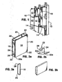
Figure 1 , the cladding system in accordance with an embodiment of the invention comprises an array of rectangular box-likeglazed cladding units 10 mounted onstructural support members 12, which typically form part of the frame of a building to be clad.Figure 1 shows a demonstration system in which thecladding units 10 are mounted onto a wooden frame structure in a continuous array forming a wall. - The
cladding units 10 are mounted onto the frame structure by means of a point-support attachment system to be described in more detail. Each cladding unit is supported at its corners. The lower twocorners 14 support the deadweight of the cladding unit itself. The upper twocorners 16 allow for upward vertical movement to accommodate thermal expansion and movement of the building itself. The attachment system also locks the cladding units against the structure in a direction normal to the plane of the wall that the cladding units are secured against windload. - As shown in
Figure 2 , the glazed cladding unit in accordance with an embodiment of the invention comprises a pair of glass panes or lites separated by a rectangularaluminum spacer frame 18 defining a box-like structure. Glass panes or "lites" 20 having a thickness of less than 9 mm, and preferably between 3 and 6 mm, are attached at their periphery to thespacer frame 18 by means of commercial silicone glazing sealant. It is found that such a construction can be made highly rigid by using a sufficiently strong spacer frame, increasing the spacing of the glass lites, preferably to 63.5 cm (or about 2.5") for a 1219 mm x 1219 mm (48" x 48") spacer frame. Indeed, it is anticipated that it will be possible to make panes up to 1.2 m x 2.4 m (4' x 8') or more, or by including a light-transmissive honeycomb insert between the panes. The honeycomb insert is generally made of plastic and thus has sufficient flexibility to allow for movement of the lites. - The spacer frame provides the structural strength to the unit. The silicone sealer provides sufficient resilience to allow for the thermal expansion of the lites without compromising the rigidity and structural integrity of the unit.
-
Angle pieces 22 are attached to the corners of thespacer frame 18, by screws or rivets, for example. Theangle pieces 22 support attachment elements in the form of protruding stainless steel load-bearingpins 24 withenlarged heads 26. Thepins 24 engage in slots in corresponding attachment elements mounted on the building structure. The lower angle pieces have shelves that extend beyond the spacer frame underneath the inner and outer lites. A block of rubber inserted between the shelves and the lites of glass acts as a setting block, transferring deadload from the weight of each lite into the angle piece and pin. In this way, long term dead loads on the silicone sealant and resultant creep of the glass relative to the spacer are avoided. - A section of the
spacer frame 18 is shown in more detail inFigures 3a and 3b . This is made of a generally rectangular extruded hollow aluminum section having bevelededges 28 on the inside. - Structural members are required to support the wall system or roof system. Any structural member, including steel, aluminum, or wood sections or trusses, capable of bearing wind load and dead load, may be used as support for the cladding units in accordance with the invention.
-
Figure 4 shows thebracket 30, which is attached to the structural members of the building. The bracket includes generally elbow or L-shapedslots 32 that receive thepins 24 of the attachment elements on the cladding units. -
Figure 5a is another view show asimilar bracket 30 withslot 32. Thebrackets 30 are arranged in upper and lower pairs on opposite sides of theglazing unit 10. The spacing of the upper and lower pairs ofbrackets 30 is arranged so that thepins 24 engaging the lower pair are seated firmly in the bottom of theslots 32, whereas thepins 24 engaging the upper slots are located roughly in the middle of the slots. The pins have a diameter corresponding to the width of the vertical limbs of theslots 32. This arrangement ensures that the cladding units are locked against movement in a direction normal to their surface and hence the wall of the building. This is important for ensuring resistance to windload. The lower pair ofslots 30 carries the full deadweight of thecladding unit 30. The upper pair of pins can move in the vertical direction to allow for expansion of the cladding units or movement of the building. The enlarged heads of the pins can also be located to permit lateral play, as shown inFigure 5b , so as to allow limited lateral movement of the cladding units for the same purpose. - The elbow shaped configuration of the slots allows the panels to be applied using a conventional suction cup for handling glass by simply lifting the panels and pressing them horizontally into the horizontal entrances of the
slots 32 and then sliding the units downwards, allowing the pins to drop down into the vertical portions of theslots 32 to secure the cladding units in place. Installation is therefore very quick and simple to perform. -
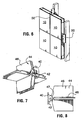
Figure 6 shows fourcladding units 10 mounted in place on a simulated building structure. Eachbracket 30 has four slots lying in the same plane to accommodate pins from all adjacent upper and lower panels. As shown thebracket 30 accommodates alower pin 24 from theupper cladding unit 10 and anupper pin 20 from thelower cladding unit 10. It also has a pair of slots to accommodate the cladding units to be installed to the right of the array shown m the drawing. For each upper and lower pair of pins, the pin on the right side is at a different level from the pin on the left side. This arrangement allows laterally adjacent cladding units to be attached to the same bracket which has four slots, one above the other without their pins colliding. - In an alternative embodiment, shown in
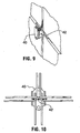
Figures 7 to 10 , the attachment system consists of abracket 40 that is attached to a structural member of the building and provided with a singlehorizontal pin 42 facing toward the cladding units. Acorner bracket 44 having right-angled plates cladding unit 10. Thebracket 44 terminates in ahook 46, which hooks over thehorizontal pin 42 of thebracket 40. As shown inFigure 7 , thehooks 46 from the brackets attached to the four adjacent cladding units lie side by side on thehorizontal pin 40, which is attached to the building structure. - As shown in
Figure 6 , a T-sectionedweathertight finishing strip 50 is inserted into the interstices or gaps between the adjacent cladding units. This can be in the form of an extruded elastomer gasket, or it can also be cure-in-placc clastomer sealant, or a combination of the above. - In one embodiment a roll-formed stainless or aluminum C-
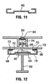
section 60 shown inFigures 11 and 12 is placed over each structural member. This C-section has a recessedmiddle portion 64, which is attached to the end of an I-section structural member forming part of a building by bolts or other suitable means. Thebracket 30 is attached to the other side of themiddle portion 64 and receives thepins 24 of the adjacent cladding units. - The in-turned
lips 68 of the C-section are provided with adhesive foam strips 70 for adherence to the backside of the backside of the cladding units. The adhesive foam strips serve as a backer for silicone sealant which is applied after cladding units are installed. By sealing all joints as well, this section forms an air seal and drip gutter to allow the system to function according to 'rain screen' principles. In the case of an overhead system, a deeper section should be used on rafters, and less deep section should be used on perlins, and sections should be tiled at perlin - rafter joints, so that any rainwater that penetrates the outer seal is wept away and down the rafter channels. - A foam-backed
rod 80 can be located behind the weathertight seal 50. - Stainless steel clips may be attached to structural members on top of air seal / drip gutter section via bolts.
- As illustrated above the cladding units are installed by inserting pins in the front of clips and then sliding the entire unit downwards, in a 'hook and pin' arrangement. Bottom pins seat in the bottom of slots, and weight of the unit is transferred into the frame. Locking clips are installed to prevent the units from escaping via moving upward. Top pins are nominally positioned in the middle of the slot, so that upper pins can slide to take up differential expansion between glass, spacer, and structural members. Besides bearing weight of the units and locking this units in place, this 'hook and pin' clip system is capable of beating significant wind loads, which act normal to the glass surface.
- The pin system allows units to slide horizontally over a small distance relative to clips. This allows for differential expansion of components, as well as some small movement of structural member without buildup of stress on the glass panels or spacers.
- The hook and pin system allows relatively large deflection of structural members, by constraining only where necessary, and allowing freedom of movement everywhere else. The inherent structural value of the glass panel acts separately to prevent deflection of the glass edges beyond the L/175 value that is used in standard glass loading calculations.
- Glazed cladding units were fabricated that consisted of Solera® honeycomb filled translucent insulating glass units configured with 6mm glass on each side, and 'S' style aluminum spacer frame at the periphery. Separation between lites of glass was 63.5 mm (2.5"), and combination of spacer, glass, and silicone adhesive provide sufficient structural capacity to span 1200 mm (48") when only point-supported at four corners. Solera panels are manufactured by Advanced Glazings Ltd., Sydney NS Canada.
- The glass can be coated with a UV curing acrylic adhesive resin, before creating the honeycomb sandwich. A suitable UV curing resin can be made from a combination of acrylic monomers and oligomers, with a UV-cure catalyst, and is supplied by UCB Chemicals Ltd., Smyrna, Georgia. The panel is then cured by exposure to radiation from standard UV-B and UV-C fluorescent lamps through the glass. This honeycomb panel is very stiff and strong. Calculations show that a panel constructed in this manner of dimension 2438 mm x 1200 mm (96" x 48") is capable of supporting loads normal to its surface of up to 2441 Kg/m2 (500 Ibs per sq.ft)., when simply supported at ends separated by the 2438mm (96") dimension. This is far in excess of standard structural capabilities of monolithic glass lites, and thus, very large areas can be spanned with only corner support.
- The above units are translucent and admit diffuse light. It is possible to make them fully transparent to provide full vision through them. In this case, the cladding units may consist of two layers of glass, preferably separated by a distance greater than the above 63.5 mm (2.5") thickness with an aluminum S spacer frame, but without the honeycomb core. When using a gap larger than 25.4 mm (1"), as is necessary to get structural moment over large distances, the pressure in the cavity between the glass is equalized by venting to the outdoors in a controlled manner, such as by the use of a 0.5 mm (0.020") ID (inner diameter) x 30.4 mm (1.2") long stainless steel tube commonly used in the glass industry for that purpose. When using clear vision units, venting should be done through a dessicant cartridge to prevent buildup of humidity and resultant internal condensation within the cladding unit.
- Clear vision units with a spacing between lites in the conventional range of 12.7 mm (0.5") to 25.4mm (1") can be utilized in this system, provided that the spacer extends beyond the glass in one or more directions, forming an 'integrated spacer frame' unit. Additionally, a standard sealed insulated glass unit can be glazed in a metal or polymer frame that provides the structural capability and compatibility with the clip system.
- Thus it will be seen that the glazed cladding units in accordance with embodiments of the invention have inherent structural capacity, such that they can be secured against windload and deadload at 3 or more points only. The structural capacity is provided by increased spacing between lites, structural moment provided by the spacer, bonding of glass to a translucent insert in the space between the glass, and any combination of the above. The attachment system allow the structural cladding units to be attached directly to structural members, such that the panels are secured against windload and deadloads, but with sufficient freedom of movement to accommodate differential thermal expansion, load-induced movements, and structural movements of the building structure itself without applying damaging stress to the glazing panels.
- The weathertight finish covers the exterior of the spaces between units. The drip gutter system that is placed between the supporting structural members and the glass cladding units catches and weeps away any rainwater that may work its way past the outer seals, and forms an inner seal as per the rain screen principle.
Claims (16)
- A point-supported cladding system for finishing the exterior of a building or like structure, comprising:a plurality of like rigid box-like glazed cladding units (10);
each cladding unit comprising:a rigid spacer frame (18) bounding said cladding unit (10);a pair of parallel light-transmissive glass lites (20) having a thickness ofnot more than about 9 mm mounted at their periphery on said rigid spacer frame (18) by means of a resilient seal; anda plurality of first attachment elements provided at discrete attachment points on said cladding unit, anda plurality of complementary second attachment elements for mounting on structural members of said building;characterised by
said first attachment elements are horizontally protruding pins (24) adjacent each corner (14, 16) of said cladding unit (10) and arranged as upper and lower pairs of pins, the pins of each of said upper and lower pairs being arranged on the right and left sides of the cladding unit respectively, the upper pair of pins being separated by a first vertical distance and the lower pair of pins being separated by a second vertical distance, said cladding unit being dimensioned and configured to have sufficient rigidity to maintain its structural integrity when supported only by said pins; and
said second attachment elements are a plurality of brackets (30) for mounting on structural members (12) of said building adjacent to corners (14,16) of each cladding unit (10), each said bracket (30) comprising a protruding plate with an outer vertical edge, and lateral portions for attachment to said structural members (12), each said plate having a series of angled slots (32) formed therein arranged in a single line one above the other, including an upper pair of slots and a lower pair of slots, wherein the difference in height between said lower pair of slots is equal to the first vertical distance and the difference in height between said upper pair of slots is equal to the second vertical distance wherein the upper pair of slots are adapted to receive the lower pin from each adjacent upper panel and wherein the lower pair of slots are adapted to receive the upper pin from each adjacent lower panel, each said slot (32) having a laterally extending portion terminating in an opening in said outer vertical edge, and a vertical portion with a blind lower end, said vertical portion merging at an upper end with an inner end of said lateral portion;whereby installation of said cladding units (10) is achieved by engaging said pins (24) with corresponding said openings, displacing said cladding units (10) laterally into said slots (32) until said pins (24) reach the vertical portions thereof, whereupon said pins (24) drop into said vertical portions to retain said cladding units in a contiguous array on said building and thereby provide an exterior wall of said building, said pins (24) and brackets (30) bearing the load of said cladding units (10) and locking said cladding units (10) against movement in a direction normal to said wall while permitting limited freedom of movement of said cladding units (10) relative to each other and said building in a plane parallel to said wall, and whereby said arrangement of pins (24) and slots (32) permits said cladding units (10) to be mounted in a contiguous fashion on said wall by said brackets (30). - A point-supported cladding system as claimed in claim 1, wherein said slots (32) have an elbow configuration to permit said pins (24) to be presented to said slots in a generally horizontal direction and then allowed to drop down into a generally vertical retaining portion.
- A point-supported cladding system as claimed in claim 2, wherein said pins have an enlarged head to assist in their retention in said slots.
- A point-supported cladding system as claimed in claim 3, wherein said enlarged head allows lateral play in said slots.
- A point-supported cladding system as claimed in any of claims 1 to 4, wherein said slots have an inverted L-shape.
- A point-supported cladding system as claimed in any one of claims to 5, wherein said structural integrity is ensured by said lites (20) having a separation that is greater than a predetermined minimum value dependent on the size of said cladding units.
- A point-supported cladding system as claimed in claim 6, wherein said separation is at least 63.5 mm (2.5") and said cladding units are about 1219 mm square (48" square).
- A point-supported cladding system as claimed in any one of claims 1 to 5, wherein said structural integrity is ensured by a translucent insert provided between said lites (20).
- A point-supported cladding system as claimed in claim 8, wherein said translucent insert is a plastic honeycomb insert.
- A point-supported cladding system as claimed in claim 9, wherein said lites (20) are coated with an acrylic adhesive resin securing said lites (20) to said honeycomb insert.
- A point-supported cladding system as claimed in any preceding claim, further comprising a venting conduit for venting the interior of said cladding units to the outside.
- A point-supported cladding system as claimed in any preceding claim, wherein said lites (20) are transparent.
- A point-supported cladding system as claimed in claim 12, further comprising a dessicant in said conduit to prevent build-up of humidity in the interior of said cladding units (10).
- A point-supported cladding system as claimed in any preceding claim, wherein said seal is made of glazing silicone.
- A point-supported cladding system as claimed in any preceding claim, further comprising a weather-tight finishing material for insertion into interstices between adjacent said cladding units of said contiguous array.
- A point-supported cladding system as claimed in claim 15, further comprising a drip gutter for mounting on said structural members behind said cladding units to catch any rainwater that works its way behind the weathertight finishing material, thereby implementing rainscreen principles.
Applications Claiming Priority (2)
| Application Number | Priority Date | Filing Date | Title |
|---|---|---|---|
| US855306 | 2004-05-27 | ||
| US10/855,306 US7540119B2 (en) | 2004-05-27 | 2004-05-27 | Point-supported glazed cladding system |
Publications (3)
| Publication Number | Publication Date |
|---|---|
| EP1600596A2 EP1600596A2 (en) | 2005-11-30 |
| EP1600596A3 EP1600596A3 (en) | 2006-08-09 |
| EP1600596B1 true EP1600596B1 (en) | 2010-08-25 |
Family
ID=34939939
Family Applications (1)
| Application Number | Title | Priority Date | Filing Date |
|---|---|---|---|
| EP05104363A Active EP1600596B1 (en) | 2004-05-27 | 2005-05-23 | Point-Supported Glazed Cladding System |
Country Status (4)
| Country | Link |
|---|---|
| US (1) | US7540119B2 (en) |
| EP (1) | EP1600596B1 (en) |
| CA (1) | CA2507558C (en) |
| DE (1) | DE602005023095D1 (en) |
Families Citing this family (12)
| Publication number | Priority date | Publication date | Assignee | Title |
|---|---|---|---|---|
| MXPA02000853A (en) * | 2002-01-23 | 2003-07-30 | De Leon Fierro Rigoberto | Walls with mortised tiles and metallic structure for multiple uses such as floors, walls and gradins. |
| TWI416001B (en) * | 2007-09-21 | 2013-11-21 | Formosa Stone Panels Inc | An architectural decoration composing module and using the architectural module to modify the architecture wall or floor |
| US8322103B1 (en) * | 2008-10-22 | 2012-12-04 | Charles D Kownacki | Faux brick with suspension system |
| FR2964684B1 (en) * | 2010-09-15 | 2019-08-02 | Sb Construction Bois | ELEMENT FOR FIXING A PANEL ON A FACADE, PANEL FOR COVERING A FACADE AND METHOD FIXING SUCH A PANEL ON A FACADE |
| US8826611B2 (en) | 2010-12-23 | 2014-09-09 | Saint-Gobain Performance Plastics Corporation | Structural glazing spacer |
| CA2858724C (en) * | 2011-12-14 | 2021-03-09 | Pella Corporation | Thermal break for curtain wall |
| US8919070B2 (en) | 2012-08-30 | 2014-12-30 | Technoform Holding GmbH | Spacer for retaining cladding element on structural building element |
| US9243442B2 (en) | 2013-01-28 | 2016-01-26 | Hok Product Design, Llc | Panelized shadow box |
| USD837417S1 (en) * | 2014-04-09 | 2019-01-01 | Rex Britton | Structural building panel |
| USD837418S1 (en) * | 2014-04-09 | 2019-01-01 | Rex Britton | Structural building panel |
| US11643864B2 (en) | 2018-01-23 | 2023-05-09 | Pella Corporation | Screen edge retention and screen rethreading features for a hidden screen assembly and a fenestration assembly |
| CN110374227B (en) * | 2019-07-24 | 2024-03-29 | 沈阳新大陆建筑设计有限公司 | External net sheet type wall heat preservation and decoration system and construction method thereof |
Family Cites Families (14)
| Publication number | Priority date | Publication date | Assignee | Title |
|---|---|---|---|---|
| US2490663A (en) * | 1945-07-23 | 1949-12-06 | Cuyahoga Spring Company | Wall panel securing means |
| US4198796A (en) * | 1977-09-07 | 1980-04-22 | Massachusetts Institute Of Technology | Thermal insulation structure |
| DE3128246A1 (en) * | 1981-07-17 | 1983-02-24 | Klaus 7928 Giengen Wöbke | Mounting system for facing-masonrywork elements |
| DE3612681A1 (en) | 1985-12-23 | 1987-07-02 | Gartner & Co J | Glazing |
| AT386635B (en) * | 1987-03-20 | 1988-09-26 | Eckelt Josef | GLASS FACADE WITH GLASS PANELS |
| US4817352A (en) * | 1988-02-18 | 1989-04-04 | Delange Daniel H | Display wall system |
| FR2651519B1 (en) * | 1989-09-04 | 1993-02-19 | Felix Andre | COVERING PANEL WITH A METAL FRAME FOR THE OUTER SURFACE OF A FACADE. |
| US5369924A (en) | 1993-04-30 | 1994-12-06 | Neudorf; Peter | Structural curtainwall system and components therefor |
| DE4333522A1 (en) | 1993-10-01 | 1995-04-06 | Wicona Bausysteme Gmbh | Heat-insulated infilling element for the façades of buildings |
| US5522193A (en) * | 1994-02-23 | 1996-06-04 | Sommerstein; Michael | Panel mounting arrangement |
| CA2282998C (en) | 1999-09-22 | 2007-09-11 | Douglas I. Milburn | Light-diffusing, insulating, glazing system component |
| AU2002212096A1 (en) | 2000-10-27 | 2002-05-06 | Kim Egholm | An optical screen element |
| US6988341B2 (en) * | 2002-05-08 | 2006-01-24 | Regina Samuel R | Ventilated interlocking translucent blocks |
| DE20304865U1 (en) | 2003-03-25 | 2003-06-12 | Bangratz Rene | Double glazing glass, has mounting device inside cavity glued to both panes and secured to fastener on outside of panes |
-
2004
- 2004-05-27 US US10/855,306 patent/US7540119B2/en active Active
-
2005
- 2005-05-17 CA CA2507558A patent/CA2507558C/en active Active
- 2005-05-23 DE DE602005023095T patent/DE602005023095D1/en active Active
- 2005-05-23 EP EP05104363A patent/EP1600596B1/en active Active
Also Published As
| Publication number | Publication date |
|---|---|
| CA2507558C (en) | 2014-01-28 |
| US20050262783A1 (en) | 2005-12-01 |
| EP1600596A3 (en) | 2006-08-09 |
| DE602005023095D1 (en) | 2010-10-07 |
| CA2507558A1 (en) | 2005-11-27 |
| EP1600596A2 (en) | 2005-11-30 |
| US7540119B2 (en) | 2009-06-02 |
Similar Documents
| Publication | Publication Date | Title |
|---|---|---|
| EP1600596B1 (en) | Point-Supported Glazed Cladding System | |
| CA1286158C (en) | Structural interface and weatherseal for structurally bonded glazing | |
| CA2740151C (en) | Toggle assembly for retaining a panel member | |
| US4899508A (en) | Panel and glass curtain wall system | |
| US5381637A (en) | Stopless butt-joint curtainwall system | |
| US7162842B2 (en) | Structural element system and structural elements of such system for curtain facades, facade linings, sun rooms, soundproofing walls, fair buildings and the like | |
| US7827746B2 (en) | Hybrid window wall/curtain wall system and method of installation | |
| CN103339337B (en) | For the assembly of structure | |
| CA2059620C (en) | Glazing bar system | |
| EP3103954A2 (en) | Double glazing unit comprising a prestressed cable in its moulded border element | |
| EP2672051B1 (en) | Door or window | |
| US9091063B2 (en) | Hidden frame airloop window wall unit | |
| EP2687669A2 (en) | Method of mounting an insulating glazing panel to a window frame by means of an embedded fitting in its extruded border | |
| US20050138889A1 (en) | Curtain wall system with enhanced resistance to blast forces | |
| EP2246495A1 (en) | Partitioning system | |
| US8028479B2 (en) | Interlocking structural glazing panels | |
| CN213391715U (en) | Curtain wall type window | |
| CN111677410B (en) | Curtain wall type window | |
| US20200040575A1 (en) | Glazing Assembly | |
| RU2741424C1 (en) | System of profiles for fixation of panel on facade of building and method of installation thereof | |
| DE20319907U1 (en) | Glazing system, in particular, for hall walls and building facades consists of glass elements in the form of U-profiles surrounding a glass wool layer | |
| CA2510989A1 (en) | Hybrid window wall/curtain wall system and method of installation | |
| EP0489189A1 (en) | Method for the sheathing of buildings by means of double glass façade panels | |
| EP2186960A2 (en) | Frame members for curtain walls | |
| AU770776B2 (en) | Method for fastening cladding panels to building frames |
Legal Events
| Date | Code | Title | Description |
|---|---|---|---|
| PUAI | Public reference made under article 153(3) epc to a published international application that has entered the european phase |
Free format text: ORIGINAL CODE: 0009012 |
|
| AK | Designated contracting states |
Kind code of ref document: A2 Designated state(s): AT BE BG CH CY CZ DE DK EE ES FI FR GB GR HU IE IS IT LI LT LU MC NL PL PT RO SE SI SK TR |
|
| AX | Request for extension of the european patent |
Extension state: AL BA HR LV MK YU |
|
| RAP1 | Party data changed (applicant data changed or rights of an application transferred) |
Owner name: ADVANCED GLAZING TECHNOLOGIES LIMITED |
|
| PUAL | Search report despatched |
Free format text: ORIGINAL CODE: 0009013 |
|
| AK | Designated contracting states |
Kind code of ref document: A3 Designated state(s): AT BE BG CH CY CZ DE DK EE ES FI FR GB GR HU IE IS IT LI LT LU MC NL PL PT RO SE SI SK TR |
|
| AX | Request for extension of the european patent |
Extension state: AL BA HR LV MK YU |
|
| 17P | Request for examination filed |
Effective date: 20070130 |
|
| AKX | Designation fees paid |
Designated state(s): DE FR GB |
|
| 17Q | First examination report despatched |
Effective date: 20090204 |
|
| GRAJ | Information related to disapproval of communication of intention to grant by the applicant or resumption of examination proceedings by the epo deleted |
Free format text: ORIGINAL CODE: EPIDOSDIGR1 |
|
| GRAP | Despatch of communication of intention to grant a patent |
Free format text: ORIGINAL CODE: EPIDOSNIGR1 |
|
| GRAP | Despatch of communication of intention to grant a patent |
Free format text: ORIGINAL CODE: EPIDOSNIGR1 |
|
| RIN1 | Information on inventor provided before grant (corrected) |
Inventor name: MILBURN, DOUG |
|
| GRAS | Grant fee paid |
Free format text: ORIGINAL CODE: EPIDOSNIGR3 |
|
| GRAA | (expected) grant |
Free format text: ORIGINAL CODE: 0009210 |
|
| AK | Designated contracting states |
Kind code of ref document: B1 Designated state(s): DE FR GB |
|
| REG | Reference to a national code |
Ref country code: GB Ref legal event code: FG4D |
|
| REF | Corresponds to: |
Ref document number: 602005023095 Country of ref document: DE Date of ref document: 20101007 Kind code of ref document: P |
|
| PLBE | No opposition filed within time limit |
Free format text: ORIGINAL CODE: 0009261 |
|
| STAA | Information on the status of an ep patent application or granted ep patent |
Free format text: STATUS: NO OPPOSITION FILED WITHIN TIME LIMIT |
|
| 26N | No opposition filed |
Effective date: 20110526 |
|
| REG | Reference to a national code |
Ref country code: DE Ref legal event code: R097 Ref document number: 602005023095 Country of ref document: DE Effective date: 20110526 |
|
| REG | Reference to a national code |
Ref country code: FR Ref legal event code: ST Effective date: 20120131 |
|
| REG | Reference to a national code |
Ref country code: DE Ref legal event code: R119 Ref document number: 602005023095 Country of ref document: DE Effective date: 20111201 |
|
| PG25 | Lapsed in a contracting state [announced via postgrant information from national office to epo] |
Ref country code: FR Free format text: LAPSE BECAUSE OF NON-PAYMENT OF DUE FEES Effective date: 20110531 |
|
| PG25 | Lapsed in a contracting state [announced via postgrant information from national office to epo] |
Ref country code: DE Free format text: LAPSE BECAUSE OF NON-PAYMENT OF DUE FEES Effective date: 20111201 |
|
| P01 | Opt-out of the competence of the unified patent court (upc) registered |
Effective date: 20230525 |
|
| PGFP | Annual fee paid to national office [announced via postgrant information from national office to epo] |
Ref country code: GB Payment date: 20230518 Year of fee payment: 19 |