EP3706552B1 - Hydrauliksystem für eine multiprozess-maschine und die multiprozessmaschine mit ihm - Google Patents
Hydrauliksystem für eine multiprozess-maschine und die multiprozessmaschine mit ihm Download PDFInfo
- Publication number
- EP3706552B1 EP3706552B1 EP18827141.5A EP18827141A EP3706552B1 EP 3706552 B1 EP3706552 B1 EP 3706552B1 EP 18827141 A EP18827141 A EP 18827141A EP 3706552 B1 EP3706552 B1 EP 3706552B1
- Authority
- EP
- European Patent Office
- Prior art keywords
- pressure
- hydraulic
- process machine
- valve
- hydraulic system
- Prior art date
- Legal status (The legal status is an assumption and is not a legal conclusion. Google has not performed a legal analysis and makes no representation as to the accuracy of the status listed.)
- Active
Links
Images


Classifications
-
- A—HUMAN NECESSITIES
- A01—AGRICULTURE; FORESTRY; ANIMAL HUSBANDRY; HUNTING; TRAPPING; FISHING
- A01G—HORTICULTURE; CULTIVATION OF VEGETABLES, FLOWERS, RICE, FRUIT, VINES, HOPS OR SEAWEED; FORESTRY; WATERING
- A01G23/00—Forestry
- A01G23/02—Transplanting, uprooting, felling or delimbing trees
- A01G23/08—Felling trees
- A01G23/083—Feller-delimbers
-
- B—PERFORMING OPERATIONS; TRANSPORTING
- B27—WORKING OR PRESERVING WOOD OR SIMILAR MATERIAL; NAILING OR STAPLING MACHINES IN GENERAL
- B27B—SAWS FOR WOOD OR SIMILAR MATERIAL; COMPONENTS OR ACCESSORIES THEREFOR
- B27B25/00—Feeding devices for timber in saw mills or sawing machines; Feeding devices for trees
- B27B25/02—Feeding devices for timber in saw mills or sawing machines; Feeding devices for trees with feed and pressure rollers
-
- E—FIXED CONSTRUCTIONS
- E02—HYDRAULIC ENGINEERING; FOUNDATIONS; SOIL SHIFTING
- E02F—DREDGING; SOIL-SHIFTING
- E02F3/00—Dredgers; Soil-shifting machines
- E02F3/04—Dredgers; Soil-shifting machines mechanically-driven
- E02F3/96—Dredgers; Soil-shifting machines mechanically-driven with arrangements for alternate or simultaneous use of different digging elements
- E02F3/963—Arrangements on backhoes for alternate use of different tools
-
- E—FIXED CONSTRUCTIONS
- E02—HYDRAULIC ENGINEERING; FOUNDATIONS; SOIL SHIFTING
- E02F—DREDGING; SOIL-SHIFTING
- E02F9/00—Component parts of dredgers or soil-shifting machines, not restricted to one of the kinds covered by groups E02F3/00 - E02F7/00
- E02F9/20—Drives; Control devices
- E02F9/22—Hydraulic or pneumatic drives
- E02F9/2217—Hydraulic or pneumatic drives with energy recovery arrangements, e.g. using accumulators, flywheels
-
- E—FIXED CONSTRUCTIONS
- E02—HYDRAULIC ENGINEERING; FOUNDATIONS; SOIL SHIFTING
- E02F—DREDGING; SOIL-SHIFTING
- E02F9/00—Component parts of dredgers or soil-shifting machines, not restricted to one of the kinds covered by groups E02F3/00 - E02F7/00
- E02F9/20—Drives; Control devices
- E02F9/22—Hydraulic or pneumatic drives
- E02F9/2278—Hydraulic circuits
- E02F9/2296—Systems with a variable displacement pump
-
- F—MECHANICAL ENGINEERING; LIGHTING; HEATING; WEAPONS; BLASTING
- F15—FLUID-PRESSURE ACTUATORS; HYDRAULICS OR PNEUMATICS IN GENERAL
- F15B—SYSTEMS ACTING BY MEANS OF FLUIDS IN GENERAL; FLUID-PRESSURE ACTUATORS, e.g. SERVOMOTORS; DETAILS OF FLUID-PRESSURE SYSTEMS, NOT OTHERWISE PROVIDED FOR
- F15B1/00—Installations or systems with accumulators; Supply reservoir or sump assemblies
- F15B1/02—Installations or systems with accumulators
- F15B1/024—Installations or systems with accumulators used as a supplementary power source, e.g. to store energy in idle periods to balance pump load
-
- F—MECHANICAL ENGINEERING; LIGHTING; HEATING; WEAPONS; BLASTING
- F15—FLUID-PRESSURE ACTUATORS; HYDRAULICS OR PNEUMATICS IN GENERAL
- F15B—SYSTEMS ACTING BY MEANS OF FLUIDS IN GENERAL; FLUID-PRESSURE ACTUATORS, e.g. SERVOMOTORS; DETAILS OF FLUID-PRESSURE SYSTEMS, NOT OTHERWISE PROVIDED FOR
- F15B1/00—Installations or systems with accumulators; Supply reservoir or sump assemblies
- F15B1/02—Installations or systems with accumulators
- F15B1/027—Installations or systems with accumulators having accumulator charging devices
- F15B1/033—Installations or systems with accumulators having accumulator charging devices with electrical control means
-
- F—MECHANICAL ENGINEERING; LIGHTING; HEATING; WEAPONS; BLASTING
- F15—FLUID-PRESSURE ACTUATORS; HYDRAULICS OR PNEUMATICS IN GENERAL
- F15B—SYSTEMS ACTING BY MEANS OF FLUIDS IN GENERAL; FLUID-PRESSURE ACTUATORS, e.g. SERVOMOTORS; DETAILS OF FLUID-PRESSURE SYSTEMS, NOT OTHERWISE PROVIDED FOR
- F15B2211/00—Circuits for servomotor systems
- F15B2211/20—Fluid pressure source, e.g. accumulator or variable axial piston pump
- F15B2211/205—Systems with pumps
- F15B2211/2053—Type of pump
- F15B2211/20546—Type of pump variable capacity
-
- F—MECHANICAL ENGINEERING; LIGHTING; HEATING; WEAPONS; BLASTING
- F15—FLUID-PRESSURE ACTUATORS; HYDRAULICS OR PNEUMATICS IN GENERAL
- F15B—SYSTEMS ACTING BY MEANS OF FLUIDS IN GENERAL; FLUID-PRESSURE ACTUATORS, e.g. SERVOMOTORS; DETAILS OF FLUID-PRESSURE SYSTEMS, NOT OTHERWISE PROVIDED FOR
- F15B2211/00—Circuits for servomotor systems
- F15B2211/20—Fluid pressure source, e.g. accumulator or variable axial piston pump
- F15B2211/21—Systems with pressure sources other than pumps, e.g. with a pyrotechnical charge
- F15B2211/212—Systems with pressure sources other than pumps, e.g. with a pyrotechnical charge the pressure sources being accumulators
-
- F—MECHANICAL ENGINEERING; LIGHTING; HEATING; WEAPONS; BLASTING
- F15—FLUID-PRESSURE ACTUATORS; HYDRAULICS OR PNEUMATICS IN GENERAL
- F15B—SYSTEMS ACTING BY MEANS OF FLUIDS IN GENERAL; FLUID-PRESSURE ACTUATORS, e.g. SERVOMOTORS; DETAILS OF FLUID-PRESSURE SYSTEMS, NOT OTHERWISE PROVIDED FOR
- F15B2211/00—Circuits for servomotor systems
- F15B2211/20—Fluid pressure source, e.g. accumulator or variable axial piston pump
- F15B2211/265—Control of multiple pressure sources
-
- F—MECHANICAL ENGINEERING; LIGHTING; HEATING; WEAPONS; BLASTING
- F15—FLUID-PRESSURE ACTUATORS; HYDRAULICS OR PNEUMATICS IN GENERAL
- F15B—SYSTEMS ACTING BY MEANS OF FLUIDS IN GENERAL; FLUID-PRESSURE ACTUATORS, e.g. SERVOMOTORS; DETAILS OF FLUID-PRESSURE SYSTEMS, NOT OTHERWISE PROVIDED FOR
- F15B2211/00—Circuits for servomotor systems
- F15B2211/70—Output members, e.g. hydraulic motors or cylinders or control therefor
- F15B2211/705—Output members, e.g. hydraulic motors or cylinders or control therefor characterised by the type of output members or actuators
- F15B2211/7058—Rotary output members
-
- F—MECHANICAL ENGINEERING; LIGHTING; HEATING; WEAPONS; BLASTING
- F15—FLUID-PRESSURE ACTUATORS; HYDRAULICS OR PNEUMATICS IN GENERAL
- F15B—SYSTEMS ACTING BY MEANS OF FLUIDS IN GENERAL; FLUID-PRESSURE ACTUATORS, e.g. SERVOMOTORS; DETAILS OF FLUID-PRESSURE SYSTEMS, NOT OTHERWISE PROVIDED FOR
- F15B2211/00—Circuits for servomotor systems
- F15B2211/70—Output members, e.g. hydraulic motors or cylinders or control therefor
- F15B2211/71—Multiple output members, e.g. multiple hydraulic motors or cylinders
- F15B2211/7114—Multiple output members, e.g. multiple hydraulic motors or cylinders with direct connection between the chambers of different actuators
- F15B2211/7128—Multiple output members, e.g. multiple hydraulic motors or cylinders with direct connection between the chambers of different actuators the chambers being connected in parallel
Definitions
- the invention is related to a hydraulic system for a multi-process machine of the type mentioned in the preamble of Claim 1 and a multi-process machine using it.
- a conventional multi-process machine includes a base machine, a boom assembly comprising at least one boom and a felling head for felling and further processing of trees.
- the felling head is arranged to be suspended on said boom via a joint, said felling head including:
- the term 'multi-process machine' which fells, delimbs and cuts trees.
- the felling head forms a loader for log processing.
- the term 'harvester' is also used.
- the tree stand is generally variable including small and large trees. So far, it has been customary to use so-called pulse harvesters on small harvester bases. These can be temporarily used to process oversized trees; however, in a normal forest, these pulse harvesters are slow.
- WO 2009/144524 A1 and US 3 880 216 A illustrate examples of such multi-process machines.
- the object of the invention is to increase the speed particularly of a roller- or track-driven felling head. Knowing that the delimbing force is very dependent on the speed, achieving even the square of speed, the simplest way to improve delimbing is to increase speed. In practice, an excavator weighing approximately 9,000 kg enables a delimbing speed of 2.5 m/s. This dimensioning has become standard over the years. Since logs approximately 5 metres long are very often processed, the work cycle of feeding and cutting generates a suitable rhythm for the utilisation of pressure accumulators.
- a pressure accumulator is efficiently used pulse-operated its use mainly comprising sawing and log feeding including their auxiliary steps.
- a key factor when using a pressure accumulator battery is to use it only for improving log feeding and to provide a direct supply line from the accumulator battery to the log feeding motor. It is also advantageous to correspondingly use a direct charging line from the pump to the accumulator battery.
- Said pressure accumulator is advantageously located on the base machine. Alternatively, generally in exceptional cases, said pressure accumulator is located on the boom assembly.
- Very smooth operation is achieved when said pressure accumulators are at least two (most preferably 3 - 6), each arranged with a different pre-charge pressure.
- the average pre-charge pressure of pressure accumulators is preferably 40% - 60%, most preferably 45% - 55% of the work pressure, and the pre-charge pressure range of pressure accumulators is 8% - 16%, most preferably 10% - 14% of the work pressure.
- said second auxiliary supply line is connected to the side that drives the hydraulic motor in the forward direction.
- Said control valve of the first auxiliary supply line is a so-called variable flow control valve or proportional valve for charging the pressure accumulator with selected output, since partial output is possible in several steps.
- the hydraulic system of the multi-process machine includes logic control for controlling the proportional control valve with partial output in selected cycles.
- the output of the chainsaw motor is preferably 70% - 100% of the output of the hydraulic motors for the feeding device without the additional output provided by the accumulator battery.
- the base machine can be an excavator weighing 7 - 10 tons and the motor output can be as low as approximately 50 kW (generally 40 kW - 55 kW) while still achieving a feed speed of almost 5 m/s.
- the motor output of the base machine is preferably 80% - 120% of the rated output of the feed motors, i.e., without the use of the accumulator battery.
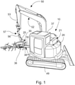
- FIG. 1 is an oblique front view of a basic example of a multi-process machine.
- Multi-process machines 31 generally include a work boom assembly 50 arranged on a base machine 10, here an excavator 50, comprising booms 52 and 53, wherein a log processing device , preferably a felling head 30, is fastened to the end of the last boom, here boom 53.
- the pivoting of the log processing device 30 to the boom 53 can be made, for example, according to prior art using two transverse rotary joints placed in a different direction relative to each other, more generally, a pivoted joint. In this case, this can also be termed a link 57.
- the log processing device 30 can be rotated with the rotating device 56 without limits around the axis of rotation of the rotating device.
- the pressure medium flow required by the actuators (the saw motor 38, for example) of the log processing device 30 can be supplied via the work boom assembly 50 using hoses, more generally, pressure medium lines, from the pressure medium pump 11 of the base machine 10.
- the motorised base machine 10 includes a power aggregate and a cabin 37.
- the work boom assembly 50 is several metres long, which mainly determines the length of the pressure medium lines.
- the base machine 10 is equipped, for example, with wheels or crawler tracks 49, as in the figure. It can be said that the log processing device 30 includes an actuator unit 44 with its basic components including a cutting device 42, a feeding device 38 and delimbing blades serving as holding clamps.
- the base machine can very well be a conventional frame-steered forest machine.
- the motor output of the base machine can be surprisingly low.
- Figure 2 includes a simple hydraulic diagram for the entire machine comprising the felling head 30 and the base machine 10. The description only applies to the arrangement according to the invention and the rest of the machine's hydraulics has been excluded.
- Pressure accumulators or the accumulator battery 21, are placed on the base machine 10. Hydraulic oil is taken for the accumulator battery 21 just before the dedicated valve assembly 12 of the base machine 10 or similar; that is, between the pump 11 and the dedicated valve assembly 12. Thus, the pressure level for the accumulators 21 is as high as possible.
- the first actuator is a non-return valve 22 to prevent the return of reserved energy.
- the following element in the line 14 is a charging valve 23, which does not allow flow towards the accumulator.
- This charging valve is advantageously a proportional valve for a more accurate control of charging, i.e., a so-called variable flow control valve.
- the accumulator battery 21 advantageously includes two or more accumulators with different pre-charge pressures. Based on experiments, a good solution is an accumulator battery 21 including, for example, 4 accumulators (generally 3 - 6) each with a different pre-charge pressure.
- the work pressure of the example machine is 250 bar. For example, the lowest pressure is 140 bar, then 150 bar and 160 bar, and the last one is 170 bar.
- a suitable total volume of accumulators 211 - 214 for an excavator weighing approximately 9,000 kg is about 15 litres ⁇ 3 litres.
- the average pre-charge pressure of pressure accumulators is 40% - 60%, most preferably 45% - 55% of the work pressure.
- the pre-charge pressure range of pressure accumulators is 8% - 16%, most preferably 10% - 14% of the work pressure.
- valve 24 From the accumulator battery 21, oil is supplied with the valve 24 to the felling head 30 along a dedicated pipe 25.
- This valve 24 is in the same package 20 with the charging valve 23 and the discharge valve 26.
- the valve 24 can be an on/off valve (closed in de-energised state); that is, it does not need to be adjustable.
- the valves 23, 24 and 26 are installed on a common base plate 28 provided with connections 281 (charge), 282 (feeding), 283 (discharge) 284 (pressure accumulator battery).
- the necessary pressure sensor 15 is connected to the base plate 28.
- accumulator battery 21 involves great safety risks. Additional oil of accumulators 21 can thus only be used to feed a log in the forward direction and additional pressurised oil only creates a risk in the boom pipework 25 during the forward feed direction. In addition, "false movements" can only appear in the forward feed direction and even then the dedicated supply valve 33 of the felling head 30 must be on.
- FIG 3 depicts the core of the hydraulic system in more detail.
- the central system 20 comprises a valve assembly installed on the base plate 28 ( Figure 5 ).
- the most essential components are the accumulator battery 21, the charging valve 26 and the discharge valve 24.
- Figure 3 shows a long separate pressure line, i.e. said dedicated line 25 leading from the base machine to the multi-process machine, generally a harvester.
- the technical capability for the base machine is achieved in the system when it is equipped with said pressure accumulator system provided with a substantially straight and separate supply from the pump to the pressure accumulator.
- the accumulator battery of the system, or the pressure accumulator unit 21, is thus advantageously located on the base machine 10 or the boom assembly.
- the pressure accumulators 211 - 214 of the accumulator battery 21 are assembled as a unit of their own in the casing 218, which is located at the rear of the cabin 37.
- the pressure accumulators are connected to a common pressure line 219.
- Figure 4b displays the casing 218 of the accumulator battery, which is also visible in Figure 1 at the rear of the cabin.
- the felling head has a separate input with an auxiliary supply line led directly to the motors.
- the use of accumulators only requires quite simple logic control for implementing the above-described operations.
- the duration of the repeating cycle comprising sawing and log feeding operations is about two seconds, of which discharging takes place for 0.5 seconds during the log feeding step and accumulators are charged almost for the rest of this time.
- the output of the chainsaw 42 motor is 70% - 100% of the total output of the hydraulic motors 32 of the feeding device without the additional output of the pressure accumulator battery 21.
- the additional instantaneous output provided by the accumulator battery 21 to the hydraulic motors of the feeding device is 50% - 100%.
- the base machine (10) can be an excavator weighing 7 - 10 tons. It is surprising that, with the invention, the motor output of an excavator or generally a base machine may be as low as 45 kW - 60 kW while still achieving a feed speed of 4 - 5 m/s.
Landscapes
- Engineering & Computer Science (AREA)
- Life Sciences & Earth Sciences (AREA)
- General Engineering & Computer Science (AREA)
- Civil Engineering (AREA)
- Structural Engineering (AREA)
- Forests & Forestry (AREA)
- Mining & Mineral Resources (AREA)
- Environmental Sciences (AREA)
- Ecology (AREA)
- Biodiversity & Conservation Biology (AREA)
- Mechanical Engineering (AREA)
- Physics & Mathematics (AREA)
- Fluid Mechanics (AREA)
- Wood Science & Technology (AREA)
- Fluid-Pressure Circuits (AREA)
- Operation Control Of Excavators (AREA)
Claims (13)
- Hydraulisches System für eine Mehrzweck-Bearbeitungsmaschine, wobei die Mehrzweck-Bearbeitungsmaschine eine Basismaschine (10), eine Auslegeranordnung (50) mit mindestens einem Ausleger (53) und einen Fällkopf (30) zum Fällen und Weiterverarbeiten von Bäumen umfasst, wobei der Fällkopf (30) so angeordnet ist, dass er über ein Gelenk (57) an dem Ausleger (53) aufgehängt ist, wobei der Fällkopf (30) Folgendes umfasst:• einen Rotator (56) zum Drehen des Fällkopfes (30),• eine Aufhängungsvorrichtung, ihre Betätigungseinheit und einen Rahmen für den Fällkopf (30), einschließlich einer Vorrichtung (38) zum Zuführen von Baumstämmen (18), die mit Hydraulikmotoren (32) ausgestattet ist, und wobei das Hydrauliksystem Folgendes umfasst:• eine Hydraulikpumpe (11) an der Basismaschine (10),• eine spezielle Ventilanordnung (12) für die Zufuhr von Medium von der Hydraulikpumpe (11) zum Fällkopf (30),• eine hydraulische Druckleitung (26) und eine Rücklaufleitung (27), die von der speziellen Ventilanordnung (12) der Basismaschine (10) zum Fällkopf (30) geführt werden, mit getrennten Ventilkanälen auf der Druckseite (P) und der Tankseite (T),• mindestens einen Hydraulikmotor (32) zur Betätigung der Vorschubvorrichtung (38),• mindestens einen Druckspeicher (21), der in dem System angeordnet ist, um die momentane Leistung des besagten Motors (32) zu erhöhen, dadurch gekennzeichnet, dass• ein spezielles Versorgungsventil (33), eine Versorgungsleitung (A/B) und eine Rücklaufleitung (B/A) sich im Fällkopf (30) befinden, wobei das spezielle Versorgungsventil (33) mit der hydraulischen Druckleitung (26) und der Rücklaufleitung (27) verbunden ist und die Versorgungsleitung (A/B) zur Zuführung von Medium zum Hydraulikmotor (32) und die Rücklaufleitung (B/A) zur Rückführung von Medium vom Hydraulikmotor (32) betätigt,• die besagten Druckspeicher (21) mindestens zwei (211 - 214) umfassen, die jeweils mit einem unterschiedlichen Vorfülldruck angeordnet sind,• das Hydrauliksystem eine logische Steuerung zur Realisierung eines impulsgesteuerten Einsatzes der Druckspeicher hauptsächlich zum Sägen und zur Stammzuführung einschließlich ihrer Hilfsschritte umfasst, und wobei die Druckspeicher nur zur Verbesserung der Stammzuführung eingesetzt werden, und das Hydrauliksystem eine direkte Zuführungsleitung von den Speichern zu dem besagten Hydraulikmotor vorsieht, wobei das System ferner umfasst• eine erste Hilfsversorgungsleitung von der Pumpe (11) zu den Druckspeichern führt, ein erstes Ende zwischen der Pumpe (11) und der speziellen Ventilanordnung (12) angeschlossen ist und eine direkte Leitung ist, die nur ein erstes Steuerventil (23) umfasst, und• eine zweite Hilfsversorgungsleitung (25), die direkt von den besagten Druckspeichern (21) zur Vorderseite des Hydraulikmotors (32) führt und ein zweites Steuerventil (24) aufweist, um den Druck der Druckspeicher (21) direkt an den Motor zu liefern.
- Hydraulisches System für eine Mehrzweck-Bearbeitungsmaschine gemäß dem Patentanspruch 1, dadurch gekennzeichnet, dass die Druckspeicher (21) auf der Basismaschine (10) angeordnet sind.
- Hydraulisches System für eine Mehrzweck-Bearbeitungsmaschine gemäß dem Patentanspruch 1, dadurch gekennzeichnet, dass die besagten Druckspeicher (21) auf der Auslegeranordnung (50) angeordnet sind.
- Hydraulisches System für eine Mehrzweck-Bearbeitungsmaschine gemäß dem Patentanspruch 3, dadurch gekennzeichnet, dass der durchschnittliche Vorfülldruck der Druckspeicher 40 % - 60 %, vorzugsweise 45 % - 55 % des Arbeitsdrucks beträgt.
- Hydraulisches System für eine Mehrzweck-Bearbeitungsmaschine gemäß dem Patentanspruch 3 oder 4, dadurch gekennzeichnet, dass der Vorfülldruckbereich der Speicher (211 - 214) 8% - 16%, besonders bevorzugt 10% - 14% des Arbeitsdrucks beträgt.
- Hydraulisches System für eine Mehrzweck-Bearbeitungsmaschine gemäß einem der Patentansprüche 1 - 5, dadurch gekennzeichnet, dass das Steuerventil (23) der ersten Hilfsversorgungsleitung (14) ein sogenanntes variables Durchflussregelventil oder Proportionalventil zum Füllen des Druckspeichers (21) mit gewählter Leistung ist.
- Hydraulisches System für eine Mehrzweck-Bearbeitungsmaschine gemäß dem Patentanspruch 6, dadurch gekennzeichnet, dass das hydraulische System für die Mehrzweck-Bearbeitungsmaschine eine Logiksteuerung zur Steuerung des Proportionalregelventils (24) mit Teilleistung in ausgewählten Zyklen umfasst.
- Hydraulisches System für eine Mehrzweck-Bearbeitungsmaschine gemäß einem der Patentansprüche 1 - 7, dadurch gekennzeichnet, dass das Ventil (23) der ersten Hilfsversorgungsleitung, das Steuerventil (24) und ein Auslassventil (26) der Druckspeicherbatterie auf einer gemeinsamen Grundplatte (28) angeordnet sind, die folgende Anschlüsse aufweist: Füllung (281) von der Pumpe, Zuführung (282) zu den Motoren, Auslass (283) zum Tank (T), Verbindung zur Druckspeicherbatterie (284).
- Hydraulisches System für eine Mehrzweck-Bearbeitungsmaschine gemäß einem der Patentansprüche 1 - 8, dadurch gekennzeichnet, dass die besagte zweite Hilfsversorgungsleitung (25) ein Rückschlagventil (31) enthält, um ein Entweichen von Druck in Richtung des Druckspeichers (21) zu verhindern.
- Mehrzweck-Bearbeitungsmaschine mit einer Basismaschine (10), einer Auslegeranordnung (50), die mit mindestens einem Ausleger (53) und einem Fällkopf (30) zum Fällen und Weiterverarbeiten von Bäumen ausgestattet ist, wobei der Fällkopf (30) über ein Gelenk (57) an dem besagten Ausleger (53) aufgehängt ist, dadurch gekennzeichnet, dass die Mehrzweck-Bearbeitungsmaschine ein Hydrauliksystem nach einem der Patentansprüche 1 - 9 aufweist.
- Mehrzweck-Bearbeitungsmaschine gemäß Patentanspruch 10, wobei der Fällkopf mit einer von einem Hydraulikmotor (38) angetriebenen Kettensäge (42) versehen ist, dadurch gekennzeichnet, dass die Motorleistung der Kettensäge 70% - 100% der Leistung der Hydraulikmotoren (32) der Vorschubeinrichtung ohne zusätzliche Leistung von den Druckspeichern (21) beträgt.
- Mehrzweck-Bearbeitungsmaschine gemäß dem Patentanspruch 10 oder 11, dadurch gekennzeichnet, dass die Basismaschine (10) ein 7 - 10 Tonnen schwerer Bagger ist.
- Mehrzweck-Bearbeitungsmaschine gemäß einem der Patentansprüche 10 - 12, dadurch gekennzeichnet, dass die Motorleistung der Basismaschine 80% - 120% der Nennleistung der Vorschubmotoren beträgt, d.h. ohne Einsatz der Druckspeicher.
Applications Claiming Priority (2)
| Application Number | Priority Date | Filing Date | Title |
|---|---|---|---|
| FI20175989A FI128709B (fi) | 2017-11-06 | 2017-11-06 | Monitoimikone |
| PCT/FI2018/050813 WO2019086769A1 (en) | 2017-11-06 | 2018-11-06 | Hydraulic system for a multi-process machine and a multi-process machine using it |
Publications (2)
| Publication Number | Publication Date |
|---|---|
| EP3706552A1 EP3706552A1 (de) | 2020-09-16 |
| EP3706552B1 true EP3706552B1 (de) | 2022-01-26 |
Family
ID=64901581
Family Applications (1)
| Application Number | Title | Priority Date | Filing Date |
|---|---|---|---|
| EP18827141.5A Active EP3706552B1 (de) | 2017-11-06 | 2018-11-06 | Hydrauliksystem für eine multiprozess-maschine und die multiprozessmaschine mit ihm |
Country Status (5)
| Country | Link |
|---|---|
| US (1) | US20210195855A1 (de) |
| EP (1) | EP3706552B1 (de) |
| JP (1) | JP7224055B2 (de) |
| FI (1) | FI128709B (de) |
| WO (1) | WO2019086769A1 (de) |
Family Cites Families (6)
| Publication number | Priority date | Publication date | Assignee | Title |
|---|---|---|---|---|
| US3880216A (en) * | 1971-11-05 | 1975-04-29 | Q M Machine Works Ltd | Method and apparatus for shearing trees |
| US3994325A (en) * | 1975-11-17 | 1976-11-30 | Caterpillar Tractor Co. | Apparatus for harvesting a tree |
| FI119274B (fi) | 2005-12-02 | 2008-09-30 | John Deere Forestry Oy | Ohjauskytkentä karsinta- ja katkaisulaitteiston syöttöelimien syöttönopeuden muuttamiseksi |
| JP2007247727A (ja) | 2006-03-15 | 2007-09-27 | Kyoritsu Kogyo Kk | 蓄圧アキュムレータや増圧ブースタによる増力可能な建設土木機械 |
| US8145395B2 (en) | 2008-05-30 | 2012-03-27 | Deere-Hitachi Speciality Products | Vehicular stored energy processor |
| FI127282B (fi) * | 2013-05-31 | 2018-03-15 | Ponsse Oyj | Metsäkoneen tehonsyöttö |
-
2017
- 2017-11-06 FI FI20175989A patent/FI128709B/fi active IP Right Grant
-
2018
- 2018-11-06 WO PCT/FI2018/050813 patent/WO2019086769A1/en not_active Ceased
- 2018-11-06 EP EP18827141.5A patent/EP3706552B1/de active Active
- 2018-11-06 US US16/756,922 patent/US20210195855A1/en not_active Abandoned
- 2018-11-06 JP JP2020524401A patent/JP7224055B2/ja active Active
Also Published As
| Publication number | Publication date |
|---|---|
| EP3706552A1 (de) | 2020-09-16 |
| US20210195855A1 (en) | 2021-07-01 |
| JP7224055B2 (ja) | 2023-02-17 |
| JP2021501856A (ja) | 2021-01-21 |
| FI128709B (fi) | 2020-10-30 |
| FI20175989A1 (fi) | 2019-05-07 |
| WO2019086769A1 (en) | 2019-05-09 |
Similar Documents
| Publication | Publication Date | Title |
|---|---|---|
| US6267163B1 (en) | Method and apparatus for operating a hydraulic drive system of a feller-buncher | |
| US20210156250A1 (en) | Advance and Retreat Automatic Control Method Based on Hydraulic Sensing Conversion and Advance and Retreat Automatic Control System Based on Hydraulic Sensing Conversion | |
| US20140069554A1 (en) | Integrated hydraulic system for harvester | |
| JP6190944B2 (ja) | 建設機械 | |
| CN105864126A (zh) | 一种节能设计的tbm推进支撑液压系统 | |
| CA2776686C (en) | Load sense hydraulic pump alignment | |
| EP3706552B1 (de) | Hydrauliksystem für eine multiprozess-maschine und die multiprozessmaschine mit ihm | |
| AU2009353981B2 (en) | Load sense and hydraulic pump management | |
| US10327395B2 (en) | Head for harvesting of trees and vehicle provided with the improved head | |
| CA2892323A1 (en) | Hydraulic drive and braking circuit for material reducing apparatus | |
| US6186198B1 (en) | Method and apparatus for distributing hydraulic power in a feller-buncher | |
| FI127282B (fi) | Metsäkoneen tehonsyöttö | |
| US3646975A (en) | Tree shearing apparatus | |
| RS64447B1 (sr) | Iverač panjeva | |
| US3874432A (en) | Tree harvesting apparatus | |
| US7152640B1 (en) | Tree cutting attachment for a skid steerloader | |
| FI129652B (fi) | Hydraulinen järjestelmä sahalaitteiston ohjaamiseksi | |
| EP3769611B1 (de) | Holzbearbeitungsvorrichtung | |
| CN219795713U (zh) | 破碎锤的复合液压控制系统、隧道施工装备 | |
| KR102769302B1 (ko) | 초고압 일체형 유압유니트 및 이를 이용한 유압장치 | |
| SU1090292A1 (ru) | Гидропривод захватно-срезающего устройства | |
| FI129142B (fi) | MENETELMÄ METSÄKONEKOURAN OHJAAMISEKSI, METSÄKONEKOURA ja TYÖKONE | |
| KR20040087354A (ko) | 중장비 연결형 암반 절개장치 | |
| SU1683568A1 (ru) | Машина дл валки и последующей трелевки деревьев | |
| IT202100030839A1 (it) | Macchina laterale, in particolare per triturare e/o tagliare erba, sterpaglie, rami |
Legal Events
| Date | Code | Title | Description |
|---|---|---|---|
| STAA | Information on the status of an ep patent application or granted ep patent |
Free format text: STATUS: UNKNOWN |
|
| STAA | Information on the status of an ep patent application or granted ep patent |
Free format text: STATUS: THE INTERNATIONAL PUBLICATION HAS BEEN MADE |
|
| PUAI | Public reference made under article 153(3) epc to a published international application that has entered the european phase |
Free format text: ORIGINAL CODE: 0009012 |
|
| STAA | Information on the status of an ep patent application or granted ep patent |
Free format text: STATUS: REQUEST FOR EXAMINATION WAS MADE |
|
| 17P | Request for examination filed |
Effective date: 20200603 |
|
| AK | Designated contracting states |
Kind code of ref document: A1 Designated state(s): AL AT BE BG CH CY CZ DE DK EE ES FI FR GB GR HR HU IE IS IT LI LT LU LV MC MK MT NL NO PL PT RO RS SE SI SK SM TR |
|
| AX | Request for extension of the european patent |
Extension state: BA ME |
|
| DAV | Request for validation of the european patent (deleted) | ||
| DAX | Request for extension of the european patent (deleted) | ||
| RIC1 | Information provided on ipc code assigned before grant |
Ipc: F15B 1/033 20060101ALN20210528BHEP Ipc: E02F 9/22 20060101ALI20210528BHEP Ipc: E02F 3/96 20060101ALI20210528BHEP Ipc: A01G 23/08 20060101AFI20210528BHEP |
|
| RIC1 | Information provided on ipc code assigned before grant |
Ipc: F15B 1/033 20060101ALN20210713BHEP Ipc: E02F 9/22 20060101ALI20210713BHEP Ipc: E02F 3/96 20060101ALI20210713BHEP Ipc: A01G 23/08 20060101AFI20210713BHEP |
|
| GRAP | Despatch of communication of intention to grant a patent |
Free format text: ORIGINAL CODE: EPIDOSNIGR1 |
|
| STAA | Information on the status of an ep patent application or granted ep patent |
Free format text: STATUS: GRANT OF PATENT IS INTENDED |
|
| RIC1 | Information provided on ipc code assigned before grant |
Ipc: F15B 1/033 20060101ALN20210719BHEP Ipc: E02F 9/22 20060101ALI20210719BHEP Ipc: E02F 3/96 20060101ALI20210719BHEP Ipc: A01G 23/08 20060101AFI20210719BHEP |
|
| INTG | Intention to grant announced |
Effective date: 20210823 |
|
| GRAS | Grant fee paid |
Free format text: ORIGINAL CODE: EPIDOSNIGR3 |
|
| GRAA | (expected) grant |
Free format text: ORIGINAL CODE: 0009210 |
|
| STAA | Information on the status of an ep patent application or granted ep patent |
Free format text: STATUS: THE PATENT HAS BEEN GRANTED |
|
| AK | Designated contracting states |
Kind code of ref document: B1 Designated state(s): AL AT BE BG CH CY CZ DE DK EE ES FI FR GB GR HR HU IE IS IT LI LT LU LV MC MK MT NL NO PL PT RO RS SE SI SK SM TR |
|
| REG | Reference to a national code |
Ref country code: GB Ref legal event code: FG4D |
|
| REG | Reference to a national code |
Ref country code: CH Ref legal event code: EP |
|
| REG | Reference to a national code |
Ref country code: AT Ref legal event code: REF Ref document number: 1464554 Country of ref document: AT Kind code of ref document: T Effective date: 20220215 |
|
| REG | Reference to a national code |
Ref country code: IE Ref legal event code: FG4D |
|
| REG | Reference to a national code |
Ref country code: DE Ref legal event code: R096 Ref document number: 602018030216 Country of ref document: DE |
|
| REG | Reference to a national code |
Ref country code: SE Ref legal event code: TRGR |
|
| REG | Reference to a national code |
Ref country code: FI Ref legal event code: FGE |
|
| REG | Reference to a national code |
Ref country code: LT Ref legal event code: MG9D |
|
| REG | Reference to a national code |
Ref country code: NL Ref legal event code: MP Effective date: 20220126 |
|
| REG | Reference to a national code |
Ref country code: AT Ref legal event code: MK05 Ref document number: 1464554 Country of ref document: AT Kind code of ref document: T Effective date: 20220126 |
|
| PG25 | Lapsed in a contracting state [announced via postgrant information from national office to epo] |
Ref country code: NL Free format text: LAPSE BECAUSE OF FAILURE TO SUBMIT A TRANSLATION OF THE DESCRIPTION OR TO PAY THE FEE WITHIN THE PRESCRIBED TIME-LIMIT Effective date: 20220126 |
|
| PG25 | Lapsed in a contracting state [announced via postgrant information from national office to epo] |
Ref country code: RS Free format text: LAPSE BECAUSE OF FAILURE TO SUBMIT A TRANSLATION OF THE DESCRIPTION OR TO PAY THE FEE WITHIN THE PRESCRIBED TIME-LIMIT Effective date: 20220126 Ref country code: PT Free format text: LAPSE BECAUSE OF FAILURE TO SUBMIT A TRANSLATION OF THE DESCRIPTION OR TO PAY THE FEE WITHIN THE PRESCRIBED TIME-LIMIT Effective date: 20220526 Ref country code: NO Free format text: LAPSE BECAUSE OF FAILURE TO SUBMIT A TRANSLATION OF THE DESCRIPTION OR TO PAY THE FEE WITHIN THE PRESCRIBED TIME-LIMIT Effective date: 20220426 Ref country code: LT Free format text: LAPSE BECAUSE OF FAILURE TO SUBMIT A TRANSLATION OF THE DESCRIPTION OR TO PAY THE FEE WITHIN THE PRESCRIBED TIME-LIMIT Effective date: 20220126 Ref country code: HR Free format text: LAPSE BECAUSE OF FAILURE TO SUBMIT A TRANSLATION OF THE DESCRIPTION OR TO PAY THE FEE WITHIN THE PRESCRIBED TIME-LIMIT Effective date: 20220126 Ref country code: ES Free format text: LAPSE BECAUSE OF FAILURE TO SUBMIT A TRANSLATION OF THE DESCRIPTION OR TO PAY THE FEE WITHIN THE PRESCRIBED TIME-LIMIT Effective date: 20220126 Ref country code: BG Free format text: LAPSE BECAUSE OF FAILURE TO SUBMIT A TRANSLATION OF THE DESCRIPTION OR TO PAY THE FEE WITHIN THE PRESCRIBED TIME-LIMIT Effective date: 20220426 |
|
| PG25 | Lapsed in a contracting state [announced via postgrant information from national office to epo] |
Ref country code: PL Free format text: LAPSE BECAUSE OF FAILURE TO SUBMIT A TRANSLATION OF THE DESCRIPTION OR TO PAY THE FEE WITHIN THE PRESCRIBED TIME-LIMIT Effective date: 20220126 Ref country code: LV Free format text: LAPSE BECAUSE OF FAILURE TO SUBMIT A TRANSLATION OF THE DESCRIPTION OR TO PAY THE FEE WITHIN THE PRESCRIBED TIME-LIMIT Effective date: 20220126 Ref country code: GR Free format text: LAPSE BECAUSE OF FAILURE TO SUBMIT A TRANSLATION OF THE DESCRIPTION OR TO PAY THE FEE WITHIN THE PRESCRIBED TIME-LIMIT Effective date: 20220427 Ref country code: AT Free format text: LAPSE BECAUSE OF FAILURE TO SUBMIT A TRANSLATION OF THE DESCRIPTION OR TO PAY THE FEE WITHIN THE PRESCRIBED TIME-LIMIT Effective date: 20220126 |
|
| PG25 | Lapsed in a contracting state [announced via postgrant information from national office to epo] |
Ref country code: IS Free format text: LAPSE BECAUSE OF FAILURE TO SUBMIT A TRANSLATION OF THE DESCRIPTION OR TO PAY THE FEE WITHIN THE PRESCRIBED TIME-LIMIT Effective date: 20220526 |
|
| REG | Reference to a national code |
Ref country code: DE Ref legal event code: R097 Ref document number: 602018030216 Country of ref document: DE |
|
| PG25 | Lapsed in a contracting state [announced via postgrant information from national office to epo] |
Ref country code: SM Free format text: LAPSE BECAUSE OF FAILURE TO SUBMIT A TRANSLATION OF THE DESCRIPTION OR TO PAY THE FEE WITHIN THE PRESCRIBED TIME-LIMIT Effective date: 20220126 Ref country code: SK Free format text: LAPSE BECAUSE OF FAILURE TO SUBMIT A TRANSLATION OF THE DESCRIPTION OR TO PAY THE FEE WITHIN THE PRESCRIBED TIME-LIMIT Effective date: 20220126 Ref country code: RO Free format text: LAPSE BECAUSE OF FAILURE TO SUBMIT A TRANSLATION OF THE DESCRIPTION OR TO PAY THE FEE WITHIN THE PRESCRIBED TIME-LIMIT Effective date: 20220126 Ref country code: EE Free format text: LAPSE BECAUSE OF FAILURE TO SUBMIT A TRANSLATION OF THE DESCRIPTION OR TO PAY THE FEE WITHIN THE PRESCRIBED TIME-LIMIT Effective date: 20220126 Ref country code: DK Free format text: LAPSE BECAUSE OF FAILURE TO SUBMIT A TRANSLATION OF THE DESCRIPTION OR TO PAY THE FEE WITHIN THE PRESCRIBED TIME-LIMIT Effective date: 20220126 Ref country code: CZ Free format text: LAPSE BECAUSE OF FAILURE TO SUBMIT A TRANSLATION OF THE DESCRIPTION OR TO PAY THE FEE WITHIN THE PRESCRIBED TIME-LIMIT Effective date: 20220126 |
|
| PG25 | Lapsed in a contracting state [announced via postgrant information from national office to epo] |
Ref country code: AL Free format text: LAPSE BECAUSE OF FAILURE TO SUBMIT A TRANSLATION OF THE DESCRIPTION OR TO PAY THE FEE WITHIN THE PRESCRIBED TIME-LIMIT Effective date: 20220126 |
|
| PLBE | No opposition filed within time limit |
Free format text: ORIGINAL CODE: 0009261 |
|
| STAA | Information on the status of an ep patent application or granted ep patent |
Free format text: STATUS: NO OPPOSITION FILED WITHIN TIME LIMIT |
|
| 26N | No opposition filed |
Effective date: 20221027 |
|
| PGFP | Annual fee paid to national office [announced via postgrant information from national office to epo] |
Ref country code: GB Payment date: 20221125 Year of fee payment: 5 |
|
| PG25 | Lapsed in a contracting state [announced via postgrant information from national office to epo] |
Ref country code: SI Free format text: LAPSE BECAUSE OF FAILURE TO SUBMIT A TRANSLATION OF THE DESCRIPTION OR TO PAY THE FEE WITHIN THE PRESCRIBED TIME-LIMIT Effective date: 20220126 |
|
| PG25 | Lapsed in a contracting state [announced via postgrant information from national office to epo] |
Ref country code: MC Free format text: LAPSE BECAUSE OF FAILURE TO SUBMIT A TRANSLATION OF THE DESCRIPTION OR TO PAY THE FEE WITHIN THE PRESCRIBED TIME-LIMIT Effective date: 20220126 |
|
| REG | Reference to a national code |
Ref country code: CH Ref legal event code: PL |
|
| P01 | Opt-out of the competence of the unified patent court (upc) registered |
Effective date: 20230614 |
|
| REG | Reference to a national code |
Ref country code: BE Ref legal event code: MM Effective date: 20221130 |
|
| PG25 | Lapsed in a contracting state [announced via postgrant information from national office to epo] |
Ref country code: LI Free format text: LAPSE BECAUSE OF NON-PAYMENT OF DUE FEES Effective date: 20221130 Ref country code: IT Free format text: LAPSE BECAUSE OF FAILURE TO SUBMIT A TRANSLATION OF THE DESCRIPTION OR TO PAY THE FEE WITHIN THE PRESCRIBED TIME-LIMIT Effective date: 20220126 Ref country code: CH Free format text: LAPSE BECAUSE OF NON-PAYMENT OF DUE FEES Effective date: 20221130 |
|
| PG25 | Lapsed in a contracting state [announced via postgrant information from national office to epo] |
Ref country code: LU Free format text: LAPSE BECAUSE OF NON-PAYMENT OF DUE FEES Effective date: 20221106 |
|
| PG25 | Lapsed in a contracting state [announced via postgrant information from national office to epo] |
Ref country code: IE Free format text: LAPSE BECAUSE OF NON-PAYMENT OF DUE FEES Effective date: 20221106 |
|
| PG25 | Lapsed in a contracting state [announced via postgrant information from national office to epo] |
Ref country code: FR Free format text: LAPSE BECAUSE OF NON-PAYMENT OF DUE FEES Effective date: 20221130 Ref country code: BE Free format text: LAPSE BECAUSE OF NON-PAYMENT OF DUE FEES Effective date: 20221130 |
|
| PGFP | Annual fee paid to national office [announced via postgrant information from national office to epo] |
Ref country code: FI Payment date: 20231115 Year of fee payment: 6 |
|
| PG25 | Lapsed in a contracting state [announced via postgrant information from national office to epo] |
Ref country code: CY Free format text: LAPSE BECAUSE OF FAILURE TO SUBMIT A TRANSLATION OF THE DESCRIPTION OR TO PAY THE FEE WITHIN THE PRESCRIBED TIME-LIMIT Effective date: 20220126 |
|
| PG25 | Lapsed in a contracting state [announced via postgrant information from national office to epo] |
Ref country code: MK Free format text: LAPSE BECAUSE OF FAILURE TO SUBMIT A TRANSLATION OF THE DESCRIPTION OR TO PAY THE FEE WITHIN THE PRESCRIBED TIME-LIMIT Effective date: 20220126 Ref country code: HU Free format text: LAPSE BECAUSE OF FAILURE TO SUBMIT A TRANSLATION OF THE DESCRIPTION OR TO PAY THE FEE WITHIN THE PRESCRIBED TIME-LIMIT; INVALID AB INITIO Effective date: 20181106 |
|
| GBPC | Gb: european patent ceased through non-payment of renewal fee |
Effective date: 20231106 |
|
| PG25 | Lapsed in a contracting state [announced via postgrant information from national office to epo] |
Ref country code: MT Free format text: LAPSE BECAUSE OF FAILURE TO SUBMIT A TRANSLATION OF THE DESCRIPTION OR TO PAY THE FEE WITHIN THE PRESCRIBED TIME-LIMIT Effective date: 20220126 |
|
| PG25 | Lapsed in a contracting state [announced via postgrant information from national office to epo] |
Ref country code: GB Free format text: LAPSE BECAUSE OF NON-PAYMENT OF DUE FEES Effective date: 20231106 |
|
| PG25 | Lapsed in a contracting state [announced via postgrant information from national office to epo] |
Ref country code: GB Free format text: LAPSE BECAUSE OF NON-PAYMENT OF DUE FEES Effective date: 20231106 |
|
| PGFP | Annual fee paid to national office [announced via postgrant information from national office to epo] |
Ref country code: DE Payment date: 20241121 Year of fee payment: 7 |
|
| PGFP | Annual fee paid to national office [announced via postgrant information from national office to epo] |
Ref country code: SE Payment date: 20241115 Year of fee payment: 7 |
|
| PG25 | Lapsed in a contracting state [announced via postgrant information from national office to epo] |
Ref country code: FI Free format text: LAPSE BECAUSE OF NON-PAYMENT OF DUE FEES Effective date: 20241106 |