EP3706524B1 - Kühlvorrichtung - Google Patents
Kühlvorrichtung Download PDFInfo
- Publication number
- EP3706524B1 EP3706524B1 EP18873981.7A EP18873981A EP3706524B1 EP 3706524 B1 EP3706524 B1 EP 3706524B1 EP 18873981 A EP18873981 A EP 18873981A EP 3706524 B1 EP3706524 B1 EP 3706524B1
- Authority
- EP
- European Patent Office
- Prior art keywords
- cabinet body
- cooling medium
- cooling
- storage tank
- volume
- Prior art date
- Legal status (The legal status is an assumption and is not a legal conclusion. Google has not performed a legal analysis and makes no representation as to the accuracy of the status listed.)
- Active
Links
Images


Classifications
-
- H—ELECTRICITY
- H05—ELECTRIC TECHNIQUES NOT OTHERWISE PROVIDED FOR
- H05K—PRINTED CIRCUITS; CASINGS OR CONSTRUCTIONAL DETAILS OF ELECTRIC APPARATUS; MANUFACTURE OF ASSEMBLAGES OF ELECTRICAL COMPONENTS
- H05K7/00—Constructional details common to different types of electric apparatus
- H05K7/20—Modifications to facilitate cooling, ventilating, or heating
- H05K7/20218—Modifications to facilitate cooling, ventilating, or heating using a liquid coolant without phase change in electronic enclosures
- H05K7/20236—Modifications to facilitate cooling, ventilating, or heating using a liquid coolant without phase change in electronic enclosures by immersion
-
- H—ELECTRICITY
- H05—ELECTRIC TECHNIQUES NOT OTHERWISE PROVIDED FOR
- H05K—PRINTED CIRCUITS; CASINGS OR CONSTRUCTIONAL DETAILS OF ELECTRIC APPARATUS; MANUFACTURE OF ASSEMBLAGES OF ELECTRICAL COMPONENTS
- H05K7/00—Constructional details common to different types of electric apparatus
- H05K7/20—Modifications to facilitate cooling, ventilating, or heating
- H05K7/20218—Modifications to facilitate cooling, ventilating, or heating using a liquid coolant without phase change in electronic enclosures
- H05K7/20272—Accessories for moving fluid, for expanding fluid, for connecting fluid conduits, for distributing fluid, for removing gas or for preventing leakage, e.g. pumps, tanks or manifolds
-
- H—ELECTRICITY
- H05—ELECTRIC TECHNIQUES NOT OTHERWISE PROVIDED FOR
- H05K—PRINTED CIRCUITS; CASINGS OR CONSTRUCTIONAL DETAILS OF ELECTRIC APPARATUS; MANUFACTURE OF ASSEMBLAGES OF ELECTRICAL COMPONENTS
- H05K7/00—Constructional details common to different types of electric apparatus
- H05K7/20—Modifications to facilitate cooling, ventilating, or heating
- H05K7/20218—Modifications to facilitate cooling, ventilating, or heating using a liquid coolant without phase change in electronic enclosures
- H05K7/20281—Thermal management, e.g. liquid flow control
-
- H—ELECTRICITY
- H05—ELECTRIC TECHNIQUES NOT OTHERWISE PROVIDED FOR
- H05K—PRINTED CIRCUITS; CASINGS OR CONSTRUCTIONAL DETAILS OF ELECTRIC APPARATUS; MANUFACTURE OF ASSEMBLAGES OF ELECTRICAL COMPONENTS
- H05K7/00—Constructional details common to different types of electric apparatus
- H05K7/20—Modifications to facilitate cooling, ventilating, or heating
- H05K7/20709—Modifications to facilitate cooling, ventilating, or heating for server racks or cabinets; for data centers, e.g. 19-inch computer racks
- H05K7/20763—Liquid cooling without phase change
- H05K7/20781—Liquid cooling without phase change within cabinets for removing heat from server blades
-
- Y—GENERAL TAGGING OF NEW TECHNOLOGICAL DEVELOPMENTS; GENERAL TAGGING OF CROSS-SECTIONAL TECHNOLOGIES SPANNING OVER SEVERAL SECTIONS OF THE IPC; TECHNICAL SUBJECTS COVERED BY FORMER USPC CROSS-REFERENCE ART COLLECTIONS [XRACs] AND DIGESTS
- Y02—TECHNOLOGIES OR APPLICATIONS FOR MITIGATION OR ADAPTATION AGAINST CLIMATE CHANGE
- Y02D—CLIMATE CHANGE MITIGATION TECHNOLOGIES IN INFORMATION AND COMMUNICATION TECHNOLOGIES [ICT], I.E. INFORMATION AND COMMUNICATION TECHNOLOGIES AIMING AT THE REDUCTION OF THEIR OWN ENERGY USE
- Y02D10/00—Energy efficient computing, e.g. low power processors, power management or thermal management
Definitions
- the present specification relates to the technical field of heat dissipating apparatuses, and in particular, to a cooling apparatus according to claim 1.
- Preferred embodiments of the invention are defined by the dependent claims.
- Servers in data centers are usually cooled by way of air-conditioning and air-cooling.
- the cooling capacity provided by many data centers is approaching the limit currently. Therefore, the conventional way of air-conditioning and air-cooling has been unable to meet the cooling demand of the servers in data centers.
- air-conditioning and air-cooling ways are consuming a large amount of energy, space and cost, and the consumption is increasing.
- US2016/0113150 describes as cooling system which includes a coolant supply manifold, a multifunction coolant manifold structure, and multiple cooling structures.
- the multifunction coolant manifold structure includes a coolant-commoning manifold and an auxiliary coolant reservoir above and in fluid communication with the coolant-commoning manifold.
- US2016/234970 describes an immersion cooling tank which includes: a tank comprised of a base wall, and perimeter walls, and having a lower tank volume in which a liquid can be maintained and heated to a boiling point to generate a rising plume of vapor; a rack structure within the tank volume that supports insertion of multiple, heat dissipating electronic devices in a side-by-side vertical configuration; and a condenser configured as a plurality of individually rotatable condenser subunits, with each condenser sub-unit located above a vertical space that extends vertically from the lower tank volume and within which an electronic device can be inserted.
- US2015/245539 describes a system for cooling a CPU.
- the system has a tank for holding dielectric coolant in a liquid phase.
- the CPU is immersed in the coolant.
- a cover closes the tank. Electric pathways that convey data to/from the CPU traverse the cover. The electric pathways allow the CPU to exchange data with an external device.
- the present specification provides a cooling apparatus to improve the cooling efficiency for the servers in data centers.
- a cooling apparatus for cooling a device includes: a cabinet body configured to contain a cooling medium for at least partially immersing the to-be-cooled device; a first volumeter for detecting the volume of the cooling medium in the cabinet body; and a replenishing device including a storage tank storing a cooling medium, a driving device for driving the cooling medium between the storage tank and the cabinet body; wherein: when the first volumeter detects that the volume of the cooling medium in the cabinet body is lower than the first preset volume, then a connection between the storage tank and the cabinet body is opened and the driving device drives the cooling medium in the storage tank into the cabinet body; and when the first volumeter detects that the volume of the cooling medium in the cabinet body reaches a second preset volume, then the connection between the storage tank and the cabinet body is closed and the driving device stops driving the cooling medium into the cabinet body, wherein the second preset volume is higher than the first preset volume; and wherein: when the first volumeter detects that the volume of the cooling medium in the cabinet body is lower than the first preset volume
- the cooling apparatus further includes a second volumeter and an alarm device which are in communication connection, wherein the second volumeter is configured to detect the volume of the cooling medium in the storage tank; and, when the second volumeter detects that the volume of the cooling medium in the storage tank is lower than a second preset volume, the alarm device alarms.
- the cooling apparatus further includes a first valve and a control system, the first valve is configured for switching between mutual communication and mutual closure of the storage tank and the cabinet body, and the control system is in communication connection with both the first volumeter and the first valve; and when the first volumeter detects that the volume of the cooling medium in the cabinet body is lower than the first preset volume, the control system controls the first valve to open so that the storage tank and the cabinet body come into mutual communication; when the first volumeter detects that the volume of the cooling medium in the cabinet body reaches the first preset volume, the control system controls the first valve to close so that the storage tank and the cabinet body are closed with respect to each other.
- the first valve is configured for switching between mutual communication and mutual closure of the storage tank and the cabinet body
- the control system is in communication connection with both the first volumeter and the first valve
- the cabinet body is provided with a first diversion opening for guiding the cooling medium
- the storage tank is provided with a second diversion opening in communication with the first diversion opening
- the first valve is disposed between the first diversion opening and the second diversion opening or disposed inside the storage tank at a position corresponding to the second diversion opening.
- the storage tank is disposed above the cabinet body, and the second diversion opening is located above the first diversion opening.
- the cooling apparatus further includes a heat exchanging device, wherein one end of the heat exchanging device is provided in communication with the cabinet body, and the other end of the heat exchanging device is provided in communication with an external liquid supply apparatus; the heat exchanging device is configured to drive the cooling medium to circulate in the cabinet body and to exchange heat with the cooling medium.
- the cabinet body is provided with a first diversion opening for introducing the cooling medium and a third diversion opening for discharging the cooling medium; and the cooling apparatus comprises a filtering device, wherein the filtering device is provided with a fourth diversion opening in communication with the first diversion opening and a fifth diversion opening in communication with the third diversion opening, and the filtering device is configured to drive the cooling medium in the cabinet body to flow through the filtering device for filtering.
- the filtering device includes a filter and a driving pump provided in communication with the filter, the driving pump is configured to drive the cooling medium in the cabinet body to flow through the filter for filtering; one of the filter and the driving pump is provided with the fourth diversion opening, and the other of the filter and the driving pump is provided with the fifth diversion opening.
- the cooling apparatus further includes a first detection system and a second valve, wherein the first detection system is configured to detect the purity of the cooling medium in the cabinet body, and the second valve is disposed between the first diversion opening and the fourth diversion opening or between the third diversion opening and the fifth diversion opening; and when the first detection system detects that the purity of the cooling medium in the cabinet body is lower than a set value, the second valve is opened, and the driving pump drives the cooling medium in the cabinet body to flow through the filter for filtering.
- the first detection system is configured to detect the purity of the cooling medium in the cabinet body
- the second valve is disposed between the first diversion opening and the fourth diversion opening or between the third diversion opening and the fifth diversion opening
- the cooling apparatus further includes a storage device provided in communication with the driving pump, and the driving pump is further configured to drive the cooling medium in the cabinet body to be transferred into the storage device.
- the cooling apparatus further includes a third valve provided between the storage device and the driving pump; when the third valve is opened, the driving pump drives the cooling medium in the cabinet body to be transferred into the storage device.
- the cooling apparatus further includes a cover disposed at the top of the cabinet body, a control system in communication connection with the filtering device, and a second detection system in communication connection with the control system, the second detection system is configured to detect whether the cover is open or closed; when detecting that the cover is in a closed state, the second detection system sends a first detection signal to the control system, and the control system controls the filtering device to stop; when detecting that the cover is in an open state, the second detection system sends a second detection signal to the control system, and the control system controls the filtering device to operate.
- the cooling apparatus of the present specification As the cooling medium in the cabinet body is gradually consumed during use, when the first volumeter detects that the volume of the cooling medium in the cabinet body is lower than the first preset volume (i.e., when the volume of the cooling medium reaches the minimum requirement), the storage tank and the cabinet body come into mutual communication so that the cooling medium in the storage tank of the replenishing device is transferred into the cabinet body, thereby realizing the function of automatically replenishing the cooling medium to the cabinet body without manual replenishment, which improves the maintenance efficiency of the cooling apparatus and further improves the cooling efficiency of the cooling apparatus for servers in data centers.
- the cooling medium in the cabinet body is gradually polluted during use, the cooling medium can be filtered by the filtering device to filter out impurities in the cooling medium to ensure the normal operation of the cooling apparatus with no need of manual replacement of the cooling medium on a regular basis, which improves the maintenance efficiency of the cooling apparatus and further improves the cooling efficiency of the cooling apparatus for the servers in data centers.
- first, second, third, etc. may be used in the present specification to describe various types of information, such information should not be limited to these terms. These terms are only used to distinguish the same type of information from each other.
- first information may also be referred to as second information without departing from the scope of the present specification.
- second information may also be referred to as the first information. It depends on the context; for example, the word “if” as used herein may be interpreted as “at the time of” or “when” or “in response to a determination.”
- the present specification provides a cooling apparatus to improve the cooling efficiency for the servers in data centers.
- the cooling apparatus of the present specification will be described in detail below with reference to the drawings. In the case of no conflict, the features in the following embodiments and implementations may be combined with each other.
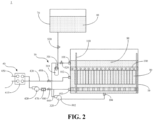
- an embodiment of the present specification provides a cooling apparatus 1 adopting a single-phase immersion liquid cooling technology for cooling a to-be-cooled device 90.
- the to-be-cooled device 90 may be a server in a data center, or may be another heat-producing apparatus that needs to be cooled.
- the cooling apparatus 1 includes a cabinet body 10, a first volumeter 110, and a replenishing device 20.
- the cabinet body 10 may be provided with plug-in components 100, and the to-be-cooled devices 90 which may adopt a sheet-type structure are sequentially plugged in the plug-in components 100.
- the cabinet body 10 here may contain a non-conductive cooling medium 80 for at least partially immersing the to-be-cooled device 90, and the first volumeter 110 is configured to detect the volume of the cooling medium 80 in the cabinet body 10.
- the replenishing device 20 includes a storage tank 210 storing the cooling medium 80, wherein the storage tank 210 and the cabinet body 10 are communicatively connected to each other.
- the first volumeter 110 detects that the volume of the cooling medium 80 in the cabinet body 10 is lower than a first preset volume, the storage tank 210 and the cabinet body 10 come into mutual communication so that the cooling medium 80 in the storage tank 210 is transferred into the cabinet body 10.
- the cooling medium 80 may completely immerse the to-be-cooled device 90 or may partially immerse the to-be-cooled device 90, which may be set according to actual needs.
- the cooling medium 80 may be a gaseous medium, a liquid medium, or a solid-liquid mixed medium, which may also be set according to actual needs.
- the first volumeter 110 may be of a contact type or a non-contact type, which may also be set according to actual needs. Corresponding changes may be made according to different cooling media 80.
- the cooling medium 80 is a liquid
- the first volumeter 110 may be a liquid level gauge.
- the cooling medium 80 completely immerses the to-be-cooled device 90, and the cooling medium 80 is a liquid 3M electronic fluorinated liquid.
- the first volumeter 110 is disposed inside the cabinet body.
- the cooling apparatus 1 of the present specification As the cooling medium 80 in the cabinet body 10 is gradually consumed during use, when the first volumeter 110 detects that the volume of the cooling medium is lower than the first preset volume (i.e., when the volume of the cooling medium in the cabinet body 10 reaches the minimum requirement), the storage tank 210 and the cabinet body 10 come into mutual communication so that the cooling medium 80 in the storage tank 210 of the replenishing device 20 is transferred into the cabinet body 10, thereby realizing the function of automatically replenishing the cooling medium to the cabinet body 10 without manual replenishment, which improves the maintenance efficiency of the cooling apparatus 1 and further improves the cooling efficiency of the cooling apparatus 1 for servers in data centers.
- the cooling apparatus 1 of the present specification further includes a first valve 510 and a control system, the first valve 510 is configured for switching between mutual communication and mutual closure of the storage tank 210 and the cabinet body 10, and the control system is in communication connection with both the first volumeter 110 and the first valve 510.
- the first volumeter 110 sends a detection signal to the control system, and the control system controls the first valve 510 to open so that the storage tank 210 and the cabinet body 10 come into mutual communication.
- the first volumeter 110 When detecting that the volume of the cooling medium 80 in the cabinet body 10 reaches the first preset volume, the first volumeter 110 sends a detection signal to the control system, and the control system controls the first valve 510 to close so that the storage tank 210 and the cabinet body 10 are closed with respect to each other.
- the control system controls the first valve 510 to open or close, thereby achieving the purpose of automatically replenishing the cabinet body 10 or stopping replenishing the cabinet body 10.
- the first valve 510 is a solenoid valve.
- the cooling apparatus 1 of the present application further includes a second volumeter 220 and an alarm device which are in communication connection, wherein the second volumeter 220 is configured to detect the volume of the cooling medium 80 in the storage tank 210.
- the alarm device alarms, further achieving the purpose of notifying an operator to replenish the storage tank 210.
- the control system is in communication connection with both the second volumeter 220 and the alarm device.
- the second volumeter 220 When detecting that the volume of the cooling medium 80 in the storage tank 210 is lower than a second preset volume, the second volumeter 220 sends a detection signal to the control signal and the control system controls the alarm device to alarm. The control system controls the alarm device to give an alarm, thereby achieving the purpose of notifying an operator to replenish the storage tank 210.
- the second volumeter 220 is disposed in the storage tank 210.
- the second volumeter 220 may be of a contact type or a non-contact type, which may also be set according to actual needs. Corresponding changes may be made according to different cooling media 80. For example, if the cooling medium 80 is a liquid, the second volumeter 220 may be a liquid level gauge.
- the cooling apparatus 1 of the present specification further includes a driving device for driving a cooling medium 80 to be transferred between the storage tank 210 and the cabinet body 10; that is, the driving device not only can drive the cooling medium 80 in the storage tank 210 to be transferred into the cabinet body 10, and but also can drive the cooling medium 80 in the cabinet body 10 to be transferred into the storage tank 210.
- the driving device may be a pump, and the control system may control the pump to operate or stop. When the cabinet body 10 needs to be replenished, the cooling medium 80 in the storage tank 210 can be transferred into the cabinet body 10 under the driving of the pump.
- the cooling medium 80 poured into the cabinet body 10 exceeds the upper limit or when it is necessary to empty the cooling medium 80 in the cabinet body 10 (such as for the purpose of relocation), the cooling medium 80 in the cabinet body 10 can be transferred into the storage tank 210 under the driving of the pump.
- the driving device is disposed in the storage tank 210.
- the first volumeter 110 When detecting that the volume of the cooling medium 80 in the cabinet body 10 is lower than the first preset volume, the first volumeter 110 sends a detection signal to the control system, and the control system controls the first valve 510 to open so that the storage tank 210 and the cabinet body 10 come into mutual communication, and the driving device is activated so that the driving device drives the cooling medium 80 in the storage tank 210 to be transferred into the cabinet body 10, and then the cabinet body 10 is automatically replenished.
- the first volumeter 110 When detecting that the volume of the cooling medium 80 in the cabinet body 10 reaches a third preset volume, the first volumeter 110 sends a detection signal to the control system, and the control system controls the first valve 510 to close so that the storage tank 210 and the cabinet body 10 are closed with respect to each other, and the driving device is stopped so that the driving device stops driving the cooling medium 80 in the storage tank 210 to be transferred into the cabinet body 10, thus stopping replenishing the cabinet body 10.
- the third preset volume here is higher than the first preset volume, which means that the first preset volume indicates the lower limit of the allowable volume range of the cooling medium 80 in the cabinet body 10 and the third preset volume indicates the upper limit of the allowable volume range of the cooling medium 80 in the cabinet body10.
- the first volumeter 110 When detecting that the volume of the cooling medium 80 in the cabinet body 10 is higher than the third preset volume, the first volumeter 110 sends a detection signal to the control system, and the control system controls the first valve 510 to open so that the storage tank 210 and the cabinet body 10 come into mutual communication, and the driving device is activated so that the driving device drives the cooling medium 80 in the cabinet body10 to be transferred into the storage tank 210, and the excessive cooling medium 80 in the cabinet body 10 is pumped into the storage tank 210 to avoid the risk of overflow of the excessive cooling medium 80 in the cabinet body 10.
- the first volumeter 110 When detecting that the volume of the cooling medium 80 in the cabinet body 10 is restored to the third preset volume, the first volumeter 110 sends a detection signal to the control system, and the control system controls the first valve 510 to close so that the storage tank 210 and the cabinet body 10 are closed with respect to each other, and the driving device is stopped so that the driving device stops driving the cooling medium 80 in the cabinet body 10 to be transferred into the storage tank 210, thus stopping pumping the cooling medium 80 from the cabinet body 10.
- the first valve 510 can be controlled directly by the control system to open so that the storage tank 210 and the cabinet body 10 come into mutual communication, and the driving device is activated so that the driving device drives the cooling medium 80 in the cabinet body 10 to be transferred into the storage tank 210 until the cooling medium 80 in the cabinet body 10 is completely pumped out; the first valve 510 is then closed by the control system so that the storage tank 210 and the cabinet body 10 are closed with respect to each other, and the driving device is stopped from pumping the cooling medium 80 out of the cabinet body 10.
- the cabinet body 10 is provided with a first diversion opening 101 for guiding the cooling medium 80
- the storage tank 210 is provided with a second diversion opening 211 in communication with the first diversion opening 101
- the first valve 510 is disposed between the first diversion opening 101 and the second diversion opening 211 or disposed inside the storage tank 210 at a position corresponding to the second diversion opening 211, and the first diversion opening 101 and the second diversion opening 211 may be connected through a pipeline.
- the storage tank 210 is disposed above the cabinet body 10, and the second diversion opening 211 is located above the first diversion opening 101 so that the liquid level of the cooling medium 80 in the storage tank 210 is higher than the liquid level of the cooling medium 80 in the cabinet body 10.
- the first valve 510 is opened so that the cooling medium 80 in the storage tank 210 can directly flow into the cabinet body 10 under the action of gravity.
- the cooling apparatus 1 of the present application further includes a heat exchanging device 40, wherein one end of the heat exchanging device 40 is provided in communication with the cabinet body 10, and the other end of the heat exchanging device 40 is provided in communication with an external liquid supply apparatus; and the heat exchanging device 40 is configured to drive the cooling medium 80 to circulate in the cabinet body 10 and to exchange heat with the cooling medium 80.
- the heat exchanging device 40 drives the cooling medium 80 to circulate in the cabinet body 10 of the cooling apparatus 1 to take away heat of the to-be-cooled device 90, and the heat exchanging device 40 exchanges heat with the external liquid supply apparatus so that the cooling medium 80 reaches a low temperature state again, and circulates into the cabinet body 10 of the cooling apparatus 1 to cool the to-be-cooled device 90 again, thus achieving the purpose of circularly and continuously discharging the heat of the to-be-cooled device 90.
- the cabinet body 10 is further provided with a diversion inlet 102 for introducing the cooling medium 80 and a diversion outlet 103 for discharging the cooling medium 80.
- the heat exchanging device 40 includes a heat exchanger 410 and a diversion pump 420.
- the heat exchanger 410 is connected to the cooling body 10 of the cooling apparatus 1 through a first circulation loop, and is connected to the external liquid supply apparatus through a second circulation loop.
- the first circulation loop includes a first pipeline 430 and a second pipeline 440
- the second circulation loop includes a third pipeline 450 and a fourth pipeline 460.
- the first pipeline 430 is provided in communication with the diversion inlet 102 on the cabinet body 10 of the cooling apparatus 1
- the second pipeline 440 is provided in communication with the diversion outlet 103 on the cabinet body 10 of the cooling apparatus 1
- the third pipeline 450 and the fourth pipeline 460 are both provided in communication with the external liquid supply apparatus.
- the heat exchanging device 40 may further include a flow meter 470, and the flow meter 470 may be disposed between the diversion pump 420 and the cabinet body 10 and used for detecting the flow rate of the cooling medium 80.
- the pressure of the diversion pump 420 may be adjusted according to the detection result of the flow meter 470, so as to achieve the purpose of adjusting the flow rate of the cooling medium 80.
- Each of the first pipeline 430 and the second pipeline 440 may be provided with a valve 480 to open or close a pipeline passage through which the cooling medium 80 circulates in the heat exchanging device 40.
- the pump drives the cooling medium 80 to circulate in the cabinet body 10 of the cooling apparatus 1 through the first circulation loop, and the cooling medium 80 takes away the heat of the to-be-cooled device 90 through the circulation in the cabinet body 10 of the cooling apparatus 1 and enters the heat exchanger 410 of the heat exchanging device 40.
- the external liquid supply apparatus can circularly provide cooling water in the second circulation loop, and the cooling medium 80 carrying the heat of the to-be-cooled device 90 may exchange heat in the heat exchanger 410 with the cooling water provided by the external liquid supply apparatus to discharge the heat carried by the cooling medium 80 so that the cooling medium 80 reaches a low temperature state again, which can cool the to-be-cooled device 90 again after circulating into the cooling apparatus 1, thus achieving the purpose of circularly and continuously discharging the heat of the to-be-cooled device 90.
- an embodiment of the present specification provides a cooling apparatus 1 adopting a single-phase immersion liquid cooling technology for cooling a to-be-cooled device 90.
- the to-be-cooled device 90 may be a server in a data center or may be another heat-producing apparatus that needs to be cooled.
- the cooling apparatus 1 includes a cabinet body 10 and a filtering device 30.
- the cabinet body 10 may be provided with plug-in components 100, and the to-be-cooled devices 90 which may adopt a sheet-type structure are sequentially plugged in the plug-in components 100.
- the cabinet body 10 may contain a cooling medium 80 for at least partially immersing the to-be-cooled device 90, and the cabinet body 10 is provided with a first diversion opening 101 for introducing the cooling medium 80 and a third diversion opening 104 for discharging the cooling medium 80.
- the filtering device 30 is provided with a fourth diversion opening 301 in communication with the first diversion opening 101 of the cabinet body 10 and a fifth diversion opening 302 in communication with the third diversion opening 104, and the filtering device 30 is configured to drive the cooling medium 80 in the cabinet body 10 to flow through the filtering device 30 for filtering.
- the cooling medium 80 may completely immerse the to-be-cooled device 90, or may partially immerse the to-be-cooled device 90, which may be set according to actual needs.
- the cooling medium 80 may be a gaseous medium, a liquid medium, or a solid-liquid mixed medium, which may also be set according to actual needs.
- the cooling medium 80 completely immerses the to-be-cooled device 90, and the cooling medium 80 is a liquid 3M electronic fluorinated liquid.
- the third diversion opening104 may be disposed at the bottom of the cabinet body 10, the first diversion opening 101 and the fourth diversion opening 301 may be connected by a pipeline, and the third diversion opening 104 and the fifth diversion opening 302 may be connected by a pipeline.
- the cooling medium 80 in the cabinet body 10 is gradually polluted during use, the cooling medium 80 can be filtered by the filtering device 30 to filter out impurities in the cooling medium 80 to ensure that the cooling apparatus 1 can operate properly with no need of manual replacement of the cooling medium 80 on a regular basis, which improves the maintenance efficiency of the cooling apparatus 1 and further improves the cooling efficiency of the cooling apparatus 1 for the servers in data centers.
- the filtering device 30 includes a filter 310 and a driving pump 320 provided in communication with the filter 310.
- the driving pump 320 is configured to drive the cooling medium 80 in the cabinet body 10 to flow through the filter 310 for filtering.
- One of the filter 310 and the driving pump 320 is provided with the fourth diversion opening 301, and the other of the filter 310 and the driving pump 320 is provided with the fifth diversion opening 302.
- the driving pump 320 is located closer to the third diversion opening 104 of the cabinet body 10, and the filter 310 is located closer to the first diversion opening 101 of the cabinet body 10; therefore, the fourth diversion opening 301 is disposed in the filter 310, and the fifth diversion opening 302 is disposed in the driving pump 320.
- the cooling medium 80 in the cabinet body 10 can be driven by the driving pump 320 to flow through the filter 310 for filtering so that impurities in the cooling medium 80 are filtered out, thus ensuring the normal operation of the cooling apparatus 1.
- the cooling apparatus 1 of the present specification further includes a control system, a first detection system, and a second valve 520.
- the second valve 520 is preferably a solenoid valve, and the control system is in communication connection with the driving pump 320, the first detection system and the second valve 520.
- the first detection system is configured to detect the purity of the cooling medium 80 in the cabinet body 10, and the second valve 520 is disposed between the first diversion opening 101 and the fourth diversion opening 301 or between the third diversion opening 104 and the fifth diversion opening 302. In the example shown in the figure, the second valve 520 is disposed between the first diversion opening 101 and the fourth diversion opening 301.
- the first detection system When the first detection system detects that the purity of the cooling medium 80 in the cabinet body 10 is lower than a set value, it indicates that the purity of the cooling medium 80 in the cabinet body 10 does not meet the requirements, the first detection system then sends a detection signal to the control system, and the control system controls the second valve 520 to open and activates the driving pump 320 so that the driving pump 320 drives the cooling medium 80 in the cabinet body 10 to flow through the filter 310 for filtering, and thus the cooling medium 80 in the cabinet body 10 is filtered automatically.
- the first detection system detects that the purity of the cooling medium 80 in the cabinet body 10 reaches a set value, it indicates that the purity of the cooling medium 80 in the cabinet body 10 meets the requirements, the first detection system then sends a detection signal to the control system, and the control system controls the second valve 520 to close and stops the driving pump 320 so that the driving pump 320 stops driving the cooling medium 80 in the cabinet body 10 to flow through the filter 310 for filtering.
- the control system may also always control the second valve 520 to open and control the driving pump 320 to always be in an operating state so that the driving pump 320 circularly drives the cooling medium 80 in the cabinet body 10 to flow through the filter 310 for filtering, thus ensuring that the cooling medium 80 in the cabinet body 10 is always kept clean.
- the cooling apparatus 1 of the present application further includes a storage device 70 provided in communication with the driving pump 320, and the driving pump 320 is further configured to drive the cooling medium 80 in the cabinet body 10 to be transferred into the storage device 70.
- the cooling medium 80 in the cabinet body 10 is transferred into the storage device 70 under the driving of the driving pump 320.
- the cooling apparatus 1 of the present specification further includes a third valve 530 disposed between the storage device 70 and the driving pump 320.
- the third valve 530 is preferably a solenoid valve.
- the third valve 530 can be controlled by the control system to open and the driving pump 320 is activated so that the driving pump 320 drives the cooling medium 80 in the cabinet body 10 to be transferred into the storage device 70 until the cooling medium 80 in the cabinet body 10 is completely pumped out; the third valve 530 is then closed by the control system, and the driving pump 320 is further stopped.
- the cooling apparatus 1 of the present specification further includes a cover disposed at the top of the cabinet body 10, a control system in communication connection with the filtering device 30, and a second detection system in communication connection with the control system, and the second detection system is configured to detect the state (open/closed) of the cover.
- the second detection system detects that the cover is in a closed state, it sends a first detection signal to the control system, and the control system controls the filtering device 30 to stop.
- the second detection system detects that the cover is in an open state, it sends a second detection signal to the control system, and the control system controls the filtering device 30 to operate. That is to say, whether the cover of the cabinet body 10 is open is considered as the trigger condition of the filtering device 30.
- the filtering device 30 operates. The filtering device 30 starts filtering the cooling medium only when the cover of the cabinet body10 is open, which can reduce energy consumption.
- the cooling apparatus 1 of the present application further includes a heat exchanging device 40, wherein one end of the heat exchanging device 40 is provided in communication with the cabinet body 10, and the other end of the heat exchanging device 40 is provided in communication with an external liquid supply apparatus; the heat exchanging device 40 is configured to drive the cooling medium 80 to circulate in the cabinet body 10 and to exchange heat with the cooling medium 80.
- the heat exchanging device 40 drives the cooling medium 80 to circulate in the cabinet body 10 of the cooling apparatus 1 to take away heat of the to-be-cooled device 90, and the heat exchanging device 40 exchanges heat with the external liquid supply apparatus so that the cooling medium 80 reaches a low temperature state again, and circulates into the cabinet body 10 of the cooling apparatus 1 to cool the to-be-cooled device 90 again, thus achieving the purpose of circularly and continuously discharging the heat of the to-be-cooled device 90.
- the cabinet body 10 is further provided with a diversion inlet 102 for introducing the cooling medium 80 and a diversion outlet 103 for discharging the cooling medium 80.
- the heat exchanging device 40 includes a heat exchanger 410 and a diversion pump 420.
- the heat exchanger 410 is connected to the cooling body 10 of the cooling apparatus 1 through a first circulation loop, and is connected to the external liquid supply apparatus through a second circulation loop.
- the first circulation loop includes a first pipeline 430 and a second pipeline 440
- the second circulation loop includes a third pipeline 450 and a fourth pipeline 460.
- the first pipeline 430 is provided in communication with the diversion inlet 102 on the cabinet body 10 of the cooling apparatus 1
- the second pipeline 440 is provided in communication with the diversion outlet 103 on the cabinet body 10 of the cooling apparatus 1
- the third pipeline 450 and the fourth pipeline 460 are both provided in communication with the external liquid supply apparatus.
- the heat exchanging device 40 may further include a flow meter 470, and the flow meter 470 may be disposed between the diversion pump 420 and the cabinet body 10 and used for detecting the flow rate of the cooling medium 80.
- the pressure of the diversion pump 420 may be adjusted according to the detection result of the flow meter 470, so as to achieve the purpose of adjusting the flow rate of the cooling medium 80.
- Each of the first pipeline 430 and the second pipeline 440 may be provided with a valve 480 to open or close a pipeline passage through which the cooling medium 80 circulates in the heat exchanging device 40.
- the pump drives the cooling medium 80 to circulate in the cabinet body 10 of the cooling apparatus 1 through the first circulation loop, and the cooling medium 80 takes away the heat of the to-be-cooled device 90 through the circulation in the cabinet body 10 of the cooling apparatus 1 and enters the heat exchanger 410 of the heat exchanging device 40.
- the external liquid supply apparatus can circularly provide cooling water in the second circulation loop, and the cooling medium 80 carrying the heat of the to-be-cooled device 90 may exchange heat in the heat exchanger 410 with the cooling water provided by the external liquid supply apparatus to discharge the heat carried by the cooling medium 80 so that the cooling medium 80 reaches a low temperature state again, which can cool the to-be-cooled device 90 again after circulating into the cooling apparatus 1, thus achieving the purpose of circularly and continuously discharging the heat of the to-be-cooled device 90.
- an embodiment of the present specification provides a cooling apparatus 1 adopting a single-phase immersion liquid cooling technology for cooling a to-be-cooled device 90.
- the to-be-cooled device 90 may be a server in a data center, or may be another heat-producing apparatus that needs to be cooled.
- the cooling apparatus 1 includes a cabinet body 10, a first volumeter 110, a replenishing device 20 and a filtering device 30.
- the cabinet body 10 may be provided with plug-in components 100, and the to-be-cooled devices 90 which may adopt a sheet-type structure are sequentially plugged in the plug-in components 100.
- the cabinet body 10 may contain a cooling medium 80 for at least partially immersing the to-be-cooled device 90; the cabinet body 10 is provided with a first diversion opening 101 for introducing the cooling medium 80 and a third diversion opening 104 for discharging the cooling medium 80; and the first volumeter 110 is configured to detect the volume of the cooling medium 80 in the cabinet body 10.
- the replenishing device 20 includes a storage tank 210 storing the cooling medium 80, wherein the storage tank 210 and the cabinet body 10 are communicatively connected to each other.
- the filtering device 30 is provided with a fourth diversion opening 301 in communication with the first diversion opening 101 of the cabinet body 10 and a fifth diversion opening 302 in communication with the third diversion opening 104, and the filtering device 30 is configured to drive the cooling medium 80 in the cabinet body 10 to flow through the filtering device 30 for filtering.
- the first volumeter 110 detects that the volume of the cooling medium 80 in the cabinet body 10 is higher than a third preset volume
- the storage tank 210 and the cabinet body 10 come into mutual communication, and the filtering device 30 drives the cooling medium 80 in the cabinet body 10 to be transferred into the storage tank 210.
- the cooling medium 80 may completely immerse the to-be-cooled device 90, or may partially immerse the to-be-cooled device 90, which may be set according to actual needs.
- the cooling medium 80 may be a gaseous medium, a liquid medium, or a solid-liquid mixed medium, which may also be set according to actual needs.
- the first volumeter 110 may be of a contact type or a non-contact type, which may also be set according to actual needs. Corresponding changes may be made according to different cooling media 80. For example, if the cooling medium 80 is a liquid, the first volumeter 110 may be a liquid level gauge.
- the cooling medium 80 completely immerses the to-be-cooled device 90, and the cooling medium 80 is a liquid 3M electronic fluorinated liquid.
- the first volumeter 110 is disposed inside the cabinet body.
- the third diversion opening104 may be disposed at the bottom of the cabinet body 10, the first diversion opening 101 and the fourth diversion opening 301 may be connected by a pipeline, and the third diversion opening 104 and the fifth diversion opening 302 may be connected by a pipeline.
- the cooling apparatus 1 of the present specification organically combines both the replenishing device 20 and the filtering device 30.
- the cooling medium 80 in the cabinet body 10 exceeds the third preset volume (i.e., when the volume is overloaded)
- the storage tank 210 and the cabinet body 10 come into mutual communication, and the filtering device 30 drives the cooling medium 80 in the cabinet body 10 to be transferred into the storage tank 210, thus avoiding the risk of overflow of the excessive cooling medium 80 in the cabinet body 10.
- the cooling apparatus 1 of the present application further includes a second volumeter 220 and an alarm device which are in communication connection, wherein the second volumeter 220 is configured to detect the volume of the cooling medium 80 in the storage tank 210.
- the alarm device alarms, further achieving the purpose of notifying an operator to replenish the storage tank 210.
- the control system is in communication connection with both the second volumeter 220 and the alarm device.
- the second volumeter 220 When detecting that the volume of the cooling medium 80 in the storage tank 210 is lower than a second preset volume, the second volumeter 220 sends a detection signal to the control signal and the control system controls the alarm device to alarm. The control system controls the alarm device to give an alarm, thereby achieving the purpose of notifying an operator to replenish the storage tank 210.
- the second volumeter 220 is disposed in the storage tank 210.
- the second volumeter 220 may be of a contact type or a non-contact type, which may also be set according to actual needs. Corresponding changes may be made according to different cooling media 80. For example, if the cooling medium 80 is a liquid, the second volumeter 220 may be a liquid level gauge.
- the filtering device 30 includes a filter 310 and a driving pump 320 provided in communication with the filter 310.
- the driving pump 320 is configured to drive the cooling medium 80 in the cabinet body 10 to flow through the filter 310 for filtering.
- One of the filter 310 and the driving pump 320 is provided with the fourth diversion opening 301, and the other of the filter 310 and the driving pump 320 is provided with the fifth diversion opening 302.
- the driving pump 320 is located closer to the third diversion opening 104 of the cabinet body 10, and the filter 310 is located closer to the first diversion opening 101 of the cabinet body 10; therefore, the fourth diversion opening 301 is disposed in the filter 310, and the fifth diversion opening 302 is disposed in the driving pump 320.
- the cooling medium 80 in the cabinet body 10 can be driven by the driving pump 320 to flow through the filter 310 for filtering so that impurities in the cooling medium 80 are filtered out, thus ensuring the normal operation of the cooling apparatus 1.
- the cooling medium 80 in the cabinet body 10 can be filtered by the filtering device 30 to filter out impurities in the cooling medium 80 to ensure the normal operation of the cooling apparatus 1 with no need of manual replacement of the cooling medium 80 on a regular basis, which improves the maintenance efficiency of the cooling apparatus 1 and further improves the cooling efficiency of the cooling apparatus 1 for the servers in data centers.
- the cooling apparatus 1 of the present specification further includes a control system, a first detection system, and a second valve 520.
- the second valve 520 is preferably a solenoid valve, and the control system is in communication connection with the driving pump 320 of the filtering device 30, the first detection system and the second valve 520.
- the first detection system is configured to detect the purity of the cooling medium 80 in the cabinet body 10, and the second valve 520 is disposed between the first diversion opening 101 and the fourth diversion opening 301 or between the third diversion opening 104 and the fifth diversion opening 302. In the example shown in the figure, the second valve 520 is disposed between the first diversion opening 101 and the fourth diversion opening 301.
- the first detection system When the first detection system detects that the purity of the cooling medium 80 in the cabinet body 10 is lower than a set value, it indicates that the purity of the cooling medium 80 in the cabinet body 10 does not meet the requirements, the first detection system then sends a detection signal to the control system, and the control system controls the second valve 520 to open and activates the driving pump 320 of the filtering device 30 so that the driving pump 320 drives the cooling medium 80 in the cabinet body 10 to flow through the filter 310 for filtering, and thus the cooling medium 80 in the cabinet body 10 is filtered automatically.
- the first detection system detects that the purity of the cooling medium 80 in the cabinet body 10 reaches a set value, it indicates that the purity of the cooling medium 80 in the cabinet body 10 meets the requirements, the first detection system then sends a detection signal to the control system, and the control system controls the second valve 520 to close and stops the driving pump 320 of the filtering device 30 so that the driving pump 320 stops driving the cooling medium 80 in the cabinet body 10 to flow through the filter 310 for filtering.
- control system may also always control the second valve 520 to open and control the driving pump 320 to always be in an operating state so that the driving pump 320 circularly drives the cooling medium 80 in the cabinet body 10 to flow through the filter 310 for filtering, thus ensuring that the cooling medium 80 in the cabinet body 10 is always kept clean.
- the cooling apparatus 1 of the present specification further includes a cover disposed at the top of the cabinet body 10 and a second detection system in communication connection with the control system, and the second detection system is configured to detect the state (open/closed) of the cover.
- the second detection system detects that the cover is in a closed state, it sends a first detection signal to the control system, and the control system controls the filtering device 30 to stop.
- the second detection system detects that the cover is in an open state, it sends a second detection signal to the control system, and the control system controls the filtering device 30 to operate. That is to say, whether the cover of the cabinet body 10 is open is considered as the trigger condition of the filtering device 30.
- the filtering device 30 operates. The filtering device 30 starts filtering the cooling medium only when the cover of the cabinet body10 is open, which can reduce energy consumption.
- the storage tank 210 of the replenishing device 20 is provided in communication with the driving pump 320 of the filtering device 30.
- the driving pump 320 of the filtering device 30 is further configured to drive a cooling medium 80 to be transferred between the storage tank 210 and the cabinet body 10; that is, the driving pump 320 of the filtering device 30 not only can drive the cooling medium 80 in the storage tank 210 to be transferred into the cabinet body 10, and but also can drive the cooling medium 80 in the cabinet body 10 to be transferred into the storage tank 210.
- the cooling medium 80 in the storage tank 210 can be transferred into the cabinet body 10 under the driving of the driving pump 320.
- the cooling medium 80 poured into the cabinet body 10 exceeds the upper limit or when it is necessary to empty the cooling medium 80 in the cabinet body 10 (such as for the purpose of relocation), the cooling medium 80 in the cabinet body 10 can be transferred into the storage tank 210 under the driving of the driving pump 320.
- the cooling apparatus 1 of the present specification further includes a third valve 530 disposed between the storage tank 210 and the driving pump 320.
- the third valve 530 is preferably a solenoid valve.
- the first volumeter 110 sends a detection signal to the control system, and the control system controls the third valve 530 to open and activates the driving pump 320 of the filtering device 30 so that the driving pump 320 drives the cooling medium 80 in the cabinet body 10 to be transferred into the storage tank 210, and the excessive cooling medium 80 in the cabinet body 10 is pumped into the storage tank 210, thus avoiding the risk of overflow of the excessive cooling medium 80 in the cabinet body 10.
- the first volumeter 110 When detecting that the volume of the cooling medium 80 in the cabinet body 10 is restored to the third preset volume, the first volumeter 110 sends a detection signal to the control system, and the control system controls the third valve 530 to close and stops the driving pump 320 of the filtering device 30 so that the driving pump 320 stops driving the cooling medium 80 in the cabinet body 10 to be transferred into the storage tank 210, thus stopping pumping the cooling medium 80 from the cabinet body 10.
- the third valve 530 can be directly controlled by the control system to open and the driving pump 320 of the filtering device 30 is activated so that the driving pump 320 drives the cooling medium 80 in the cabinet body 10 to be transferred into the storage tank 210 until the cooling medium 80 in the cabinet body 10 is completely pumped out; the third valve 530 is then closed by the control system, and the driving pump 320 is further stopped.
- the driving pump 320 of the filtering device 30 is used to perform the integrated drainage operation on the cooling medium 80 in the cabinet body 10, and no additional apparatus is required to pump the cooling medium 80 out of the cabinet body 10.
- the first volumeter 110 When detecting that the volume of the cooling medium 80 in the cabinet body 10 is lower than the first preset volume, the first volumeter 110 sends a detection signal to the control system, and the control system controls the first valve 510 to open so that the storage tank 210 and the cabinet body 10 come into mutual communication, and the driving pump 320 of the filtering device 30 is activated so that the driving pump 320 drives the cooling medium 80 in the storage tank 210 to be transferred into the cabinet body 10, and then the cabinet body 10 is automatically replenished.
- the first volumeter 110 When detecting that the volume of the cooling medium 80 in the cabinet body 10 reaches the third preset volume, the first volumeter 110 sends a detection signal to the control system, and the control system controls the first valve 510 to close so that the storage tank 210 and the cabinet body 10 are closed with respect to each other, and the driving pump 320 of the filtering device 30 is stopped so that the driving pump 320 stops driving the cooling medium 80 in the storage tank 210 to be transferred into the cabinet body 10, thus stopping replenishing the cabinet body 10.
- the third preset volume here is higher than the third preset volume, which means that the first preset volume indicates the lower limit of the allowable volume range of the cooling medium 80 in the cabinet body 10 and the third preset volume indicates the upper limit of the allowable volume range of the cooling medium 80 in the cabinet body10.
- the cooling apparatus 1 of the present specification further includes a first valve 510, the first valve 510 is configured for switching between mutual communication and mutual closure of the storage tank 210 and the cabinet body 10, and the control system is in communication connection with the driving pump 320 of the filtering device 30, the first volumeter 110, and the first valve 510.
- the first volumeter 110 When detecting that the volume of the cooling medium 80 in the cabinet body 10 is lower than the first preset volume, the first volumeter 110 sends a detection signal to the control system, and the control system controls the first valve 510 to open so that the storage tank 210 and the cabinet body 10 come into mutual communication, and the driving device is activated so that the driving pump 320 of the filtering device 30 drives the cooling medium 80 in the storage tank 210 to be transferred into the cabinet body 10, and then the cabinet body 10 is automatically replenished.
- the first volumeter 110 When detecting that the volume of the cooling medium 80 in the cabinet body 10 reaches the first preset volume, the first volumeter 110 sends a detection signal to the control system, and the control system controls the first valve 510 to close so that the storage tank 210 and the cabinet body 10 are closed with respect to each other, and the driving pump 320 of the filtering device 30 stops driving the cooling medium 80 in the storage tank 210 to be transferred into the cabinet body 10, thus stopping replenishing the cabinet body 10.
- the control system controls the first valve 510 and the driving pump 320 of the filtering device 30 to open or close, thereby achieving the purpose of automatically replenishing the cabinet body 10 or stopping replenishing the cabinet body 10 with no need of manual replenishment; therefore, the maintenance efficiency of the cooling apparatus 1 is improved, and the cooling efficiency of the cooling apparatus 1 for the servers in data centers is further improved.
- the first valve 510 is a solenoid valve.
- the storage tank 210 is provided with a second diversion opening 211 in communication with the first diversion opening 101 of the cabinet body 10, the first valve 510 is disposed between the first diversion opening 101 and the second diversion opening 211 or disposed inside the storage tank 210 at a position corresponding to the second diversion opening 211, and the first diversion opening 101 and the second diversion opening 211 may be connected through a pipeline. Further, the storage tank 210 is disposed above the cabinet body 10, and the second diversion opening 211 is located above the first diversion opening 101 so that the liquid level of the cooling medium 80 in the storage tank 210 is higher than the liquid level of the cooling medium 80 in the cabinet body 10. When the cabinet body 10 needs to be replenished, the first valve 510 is opened so that the cooling medium 80 in the storage tank 210 can directly flow into the cabinet body 10 under the action of gravity.
- the cooling apparatus 1 of the present application further includes a heat exchanging device 40, wherein one end of the heat exchanging device 40 is provided in communication with the cabinet body 10, and the other end of the heat exchanging device 40 is provided in communication with an external liquid supply apparatus; the heat exchanging device 40 is configured to drive the cooling medium 80 to circulate in the cabinet body 10 and to exchange heat with the cooling medium 80.
- the heat exchanging device 40 drives the cooling medium 80 to circulate in the cabinet body 10 of the cooling apparatus 1 to take away heat of the to-be-cooled device 90, and the heat exchanging device 40 exchanges heat with the external liquid supply apparatus so that the cooling medium 80 reaches a low temperature state again, and circulates into the cabinet body 10 of the cooling apparatus 1 to cool the to-be-cooled device 90 again, thus achieving the purpose of circularly and continuously discharging the heat of the to-be-cooled device 90.
- the cabinet body 10 is further provided with a diversion inlet 102 for introducing the cooling medium 80 and a diversion outlet 103 for discharging the cooling medium 80.
- the heat exchanging device 40 includes a heat exchanger 410 and a diversion pump 420.
- the heat exchanger 410 is connected to the cooling body 10 of the cooling apparatus 1 through a first circulation loop, and is connected to the external liquid supply apparatus through a second circulation loop.
- the first circulation loop includes a first pipeline 430 and a second pipeline 440
- the second circulation loop includes a third pipeline 450 and a fourth pipeline 460.
- the first pipeline 430 is provided in communication with the diversion inlet 102 on the cabinet body 10 of the cooling apparatus 1
- the second pipeline 440 is provided in communication with the diversion outlet 103 on the cabinet body 10 of the cooling apparatus 1
- the third pipeline 450 and the fourth pipeline 460 are both provided in communication with the external liquid supply apparatus.
- the heat exchanging device 40 may further include a flow meter 470, and the flow meter 470 may be disposed between the diversion pump 420 and the cabinet body 10 and used for detecting the flow rate of the cooling medium 80.
- the pressure of the diversion pump 420 may be adjusted according to the detection result of the flow meter 470, so as to achieve the purpose of adjusting the flow rate of the cooling medium 80.
- Each of the first pipeline 430 and the second pipeline 440 may be provided with a valve 480 to open or close a pipeline passage through which the cooling medium 80 circulates in the heat exchanging device 40.
- the pump drives the cooling medium 80 to circulate in the cabinet body 10 of the cooling apparatus 1 through the first circulation loop, and the cooling medium 80 takes away the heat of the to-be-cooled device 90 through the circulation in the cabinet body 10 of the cooling apparatus 1 and enters the heat exchanger 410 of the heat exchanging device 40.
- the external liquid supply apparatus can circularly provide cooling water in the second circulation loop, and the cooling medium 80 carrying the heat of the to-be-cooled device 90 may exchange heat in the heat exchanger 410 with the cooling water provided by the external liquid supply apparatus to discharge the heat carried by the cooling medium 80 so that the cooling medium 80 reaches a low temperature state again, which can cool the to-be-cooled device 90 again after circulating into the cooling apparatus 1, thus achieving the purpose of circularly and continuously discharging the heat of the to-be-cooled device 90.
Landscapes
- Engineering & Computer Science (AREA)
- Microelectronics & Electronic Packaging (AREA)
- Physics & Mathematics (AREA)
- Thermal Sciences (AREA)
- Computer Hardware Design (AREA)
- General Engineering & Computer Science (AREA)
- Cooling Or The Like Of Electrical Apparatus (AREA)
Claims (8)
- Kühlvorrichtung zum Kühlen eines Geräts (90), wobei die Kühlvorrichtung Folgendes umfasst:einen Schrankkörper (10), der dafür ausgestaltet ist, ein Kühlmedium (80) zum mindestens teilweisen Eintauchen des Geräts (90) zu enthalten,ein erstes Volumeter (110) zum Erkennen eines Volumens des Kühlmediums (80) in dem Schrankkörper (10), undein Auffüllgerät (20), das mit dem Schrankkörper gekoppelt ist und einen Speichertank (70, 210) umfasst, der das Kühlmedium (80) speichert,ein Antriebsgerät (320) zum Antreiben des Kühlmediums zwischen dem Speichertank (70, 210) und dem Schrankkörper (10),wobei: wenn das erste Volumeter (110) erkennt, dass das Volumen des Kühlmediums (80) in dem Schrankkörper (10) geringer ist als ein erstes voreingestelltes Volumen, dann eine Verbindung zwischen dem Speichertank (70, 210) und Schrankkörper geöffnet wird und das Antriebsgerät (320) das Kühlmedium (80) in dem Speichertank in den Schrankkörper antreibt, dadurch gekennzeichnet, dass, wenn das erste Volumeter erkennt, dass das Volumen des Kühlmediums (80) in dem Schrankkörper (10) einen zweiten voreingestellten Wert erreicht, dann die Verbindung zwischen dem Speichertank (70, 210) und dem Schrankkörper geschlossen wird und das Antriebsgerät (320) das Antreiben des Kühlmediums (80) in den Schrankkörper einstellt, wobei das zweite voreingestellte Volumen höher ist als das erste voreingestellte Volumen, undwobei: wenn das erste Volumeter (110) erkennt, dass das Volumen des Kühlmediums (80) in dem Schrankkörper ein zweites voreingestelltes Volumen überschreitet, dann eine Verbindung zwischen dem Speichertank und dem Schrankkörper geöffnet wird und das Antriebsgerät (320) das Kühlmedium (80) in dem Schrankkörper (10) in den Speichertank (70, 210) antreibt, und wenn das erste Volumeter erkennt, dass das Volumen des Kühlmediums (80) in dem Schrankkörper auf das zweite voreingestellte Volumen wiederhergestellt ist, dann die Verbindung zwischen dem Speichertank und dem Schrankkörper (10) geschlossen wird und das Antriebsgerät (320) das Antreiben des Kühlmediums (80) in den Speichertank einstellt.
- Kühlvorrichtung nach Anspruch 1, ferner ein zweites Volumeter (220) und ein Alarmgerät, das kommunikationsmäßig mit dem zweiten Volumeter gekoppelt ist, umfassend, wobei das zweite Volumeter (220) dafür ausgestaltet ist, ein Volumen des Kühlmediums (80) in dem Speichertank (70, 210) zu erkennen, und
wenn das zweite Volumeter (220) erkennt, dass das Volumen des Kühlmediums (80) in dem Speichertank (70, 210) geringer ist als ein zweites voreingestelltes Volumen, dann das Alarmgerät einen Alarm ausgibt. - Kühlvorrichtung nach Anspruch 1 oder Anspruch 2, ferner ein Ventil (510) umfassend, das zum Umschalten zwischen dem Öffnen und Schließen einer Verbindung zwischen dem Speichertank und dem Schrankkörper (10) ausgestaltet ist,
wobei, wenn das erste Volumeter (110) erkennt, dass das Volumen des Kühlmediums (80) in dem Schrankkörper (10) geringer ist als das erste voreingestellte Volumen, dann das Ventil (510) geöffnet wird, so dass die Verbindung zwischen dem Speichertank und dem Schrankkörper (10) geöffnet wird, und wenn das erste Volumeter (110) erkennt, dass das Volumen des Kühlmediums (80) in dem Schrankkörper (10) den ersten voreingestellten Wert erreicht, dann das Ventil (510) geschlossen wird, und wobei der Schrankkörper (10) eine erste Umleitungsöffnung (101) zum Führen des Kühlmediums aufweist, der Speichertank (70, 210) eine zweite Umleitungs-(211)öffnung in Kommunikation mit der ersten Umleitungsöffnung (101) aufweist und das Ventil (510) an einer Position angeordnet ist, die entweder zwischen der ersten Umleitungs-(101)Öffnung und der zweiten Umleitungsöffnung (211) liegt oder im Inneren des Speichertanks (70, 210) an einer Position, die der zweiten Umleitungsöffnung (211) entspricht. - Kühlvorrichtung nach einem vorhergehenden Anspruch, ferner ein Wärmetauschgerät (40) umfassend, wobei ein Ende des Wärmetauschgeräts mit dem Schrankkörper (10) gekoppelt ist und ein anderes Ende des Wärmetauschgeräts mit einer externen Flüssigkeitszufuhrvorrichtung gekoppelt ist, und wobei das Wärmetauschgerät (40) dafür ausgestaltet ist, das Kühlmedium (80) anzutreiben, in dem Schrankkörper (10) zu zirkulieren und Wärme mit dem Kühlmedium auszutauschen.
- Kühlvorrichtung nach Anspruch 1 oder Anspruch 2, wobei der Schrankkörper (10) eine erste Umleitungsöffnung (101) zum Aufnehmen des Kühlmediums (80) und eine zweite Umleitungsöffnung (211) zum Ablassen des Kühlmediums aufweist, und
die Kühlvorrichtung ein Filtergerät (30) umfasst, welches das Antriebsgerät (320) umfasst, wobei das Filtergerät eine dritte Umleitungsöffnung (104) in Kommunikation mit der ersten Umleitungsöffnung (101) und eine vierte Umleitungsöffnung (301) in Kommunikation mit der zweiten Umleitungsöffnung (211) umfasst und wobei das Filtergerät (30) dafür ausgestaltet ist, das Kühlmedium (80) in dem Schrankkörper (10) durch das Filtergerät hindurch anzutreiben, um das Kühlmedium zu filtern. - Kühlvorrichtung nach Anspruch 5, wobei das Filtergerät (30) einen Filter (310) umfasst und das Antriebsgerät eine Antriebspumpe (320) umfasst, die mit dem Filter gekoppelt ist, wobei die Antriebspumpe dafür ausgestaltet ist, das Kühlmedium (80) in dem Schrankkörper (10) durch den Filter (310) hindurch anzutreiben, um das Kühlmedium zu filtern, und wobei eines von dem Filter (310) und der Antriebspumpe (320) mit der dritten Umleitungsöffnung (104) versehen ist, und das andere von dem Filter und der Antriebspumpe mit der vierten Umleitungsöffnung (301) versehen ist, und
wobei die Kühlvorrichtung ferner Folgendes umfasst: ein Ventil (520), das an einer Position angeordnet ist, die entweder zwischen der ersten Umleitungsöffnung und der dritten Umleitungsöffnung liegt oder zwischen der zweiten Umleitungsöffnung und der vierten Umleitungsöffnung, wobei, wenn die Reinheit des Kühlmediums (80) in dem Schrankkörper (10) niedriger als ein Sollwert ist, dann das Ventil (520) geöffnet wird und die Antriebspumpe das Kühlmedium in dem Schrankkörper zum Filtern durch den Filter hindurch antreibt. - Kühlvorrichtung nach Anspruch 5 oder Anspruch 6, ferner eine Abdeckung umfassend, die an der Oberseite des Schrankkörpers (10) angeordnet ist, wobei, wenn die Abdeckung als in einem geschlossenen Zustand erkannt wird, dann das Filtergerät (30) angehalten wird, und wobei, wenn die Abdeckung als in einem offenen Zustand erkannt wird, dann das Filtergerät gestartet wird.
- Kühlvorrichtung nach einem der Ansprüche 5 bis 7, ferner ein Wärmetauschgerät umfassend, wobei ein Ende des Wärmetauschgeräts mit dem Schrankkörper (10) gekoppelt ist und ein anderes Ende des Wärmetauschgeräts mit einer externen Flüssigkeitszufuhrvorrichtung gekoppelt ist, und wobei das Wärmetauschgerät dafür ausgestaltet ist, das Kühlmedium anzutreiben, in dem Schrankkörper (10) zu zirkulieren und Wärme mit dem Kühlmedium (80) auszutauschen.
Applications Claiming Priority (2)
| Application Number | Priority Date | Filing Date | Title |
|---|---|---|---|
| CN201711071271.6A CN109757060B (zh) | 2017-11-03 | 2017-11-03 | 冷却设备 |
| PCT/CN2018/111625 WO2019085801A1 (zh) | 2017-11-03 | 2018-10-24 | 冷却设备 |
Publications (3)
| Publication Number | Publication Date |
|---|---|
| EP3706524A1 EP3706524A1 (de) | 2020-09-09 |
| EP3706524A4 EP3706524A4 (de) | 2021-11-10 |
| EP3706524B1 true EP3706524B1 (de) | 2024-04-17 |
Family
ID=66332850
Family Applications (1)
| Application Number | Title | Priority Date | Filing Date |
|---|---|---|---|
| EP18873981.7A Active EP3706524B1 (de) | 2017-11-03 | 2018-10-24 | Kühlvorrichtung |
Country Status (6)
| Country | Link |
|---|---|
| US (1) | US11602075B2 (de) |
| EP (1) | EP3706524B1 (de) |
| JP (1) | JP2021501950A (de) |
| CN (1) | CN109757060B (de) |
| TW (1) | TW201918676A (de) |
| WO (1) | WO2019085801A1 (de) |
Families Citing this family (16)
| Publication number | Priority date | Publication date | Assignee | Title |
|---|---|---|---|---|
| CN112020265B (zh) | 2019-05-31 | 2022-06-28 | 华为技术有限公司 | 一种散热装置及处理器 |
| US12004321B2 (en) * | 2019-06-18 | 2024-06-04 | 3M Innovative Properties Company | Rack-mountable immersion cooling system |
| CN111615297A (zh) * | 2020-05-13 | 2020-09-01 | 北京达佳互联信息技术有限公司 | 浸没式冷却设备、方法、冷却系统及计算设备 |
| US20230324322A1 (en) * | 2020-09-18 | 2023-10-12 | 3M Innovative Properties Company | Sensors For Contaminants |
| CN114389463A (zh) | 2020-10-20 | 2022-04-22 | 台达电子企业管理(上海)有限公司 | 一种用于向网络设备供电的电源系统 |
| JP7574701B2 (ja) * | 2021-03-10 | 2024-10-29 | 株式会社デンソー | 冷却装置 |
| US12245406B2 (en) * | 2021-05-07 | 2025-03-04 | Firmus Metal Technologies Singapore Pte Ltd | Tank for heat dissipation and a cooling system including the same |
| CN113347507B (zh) * | 2021-07-01 | 2022-12-27 | 北京奕信通科技有限公司 | 一种液体浸没冷却式交换机及交换机组 |
| US12317450B1 (en) | 2021-11-08 | 2025-05-27 | Rhodium Technologies LLC | Fluid circulation systems and methods for cooling having a collector |
| KR102458920B1 (ko) * | 2022-02-21 | 2022-10-25 | 삼성전자주식회사 | 유체 공급 장치 |
| US12501590B2 (en) * | 2022-09-27 | 2025-12-16 | Microsoft Technology Licensing, Llc | Systems and methods for adjusting pressure in immersion-cooled datacenters |
| US11889663B1 (en) | 2022-12-07 | 2024-01-30 | Southeast University | Immersion dual-cycle multi-mode liquid cooling regulation system and method for data center |
| CN115568193B (zh) * | 2022-12-07 | 2023-03-21 | 东南大学 | 数据中心浸没式双循环多模式液冷散热调节系统及方法 |
| KR102887794B1 (ko) * | 2023-01-18 | 2025-11-18 | 주식회사 삼화에이스 | 전자기기 냉각 시스템 |
| WO2025231145A1 (en) * | 2024-04-30 | 2025-11-06 | Green Revolution Cooling, Inc. | Servers, systems, and methods for controlling fluid levels in an immersion cooling rack in response to a change in fluid displacing equipment |
| KR102856526B1 (ko) * | 2024-08-29 | 2025-09-08 | (주)글로벌스탠다드테크놀로지 | 액침 냉각 장치 및 방법 |
Family Cites Families (52)
| Publication number | Priority date | Publication date | Assignee | Title |
|---|---|---|---|---|
| US3996136A (en) * | 1973-03-16 | 1976-12-07 | Peter Jakubek | Pump-filter for bilge water |
| JPS5853072B2 (ja) | 1976-06-02 | 1983-11-26 | 栗田工業株式会社 | 金属防食剤 |
| US4879027A (en) * | 1987-04-02 | 1989-11-07 | A. W. Schlottmann | Binary fluid system, and components thereof, for producing an impregnated metered fluid stream |
| JP2748732B2 (ja) * | 1991-07-19 | 1998-05-13 | 日本電気株式会社 | 液体冷媒循環システム |
| US5435379A (en) * | 1992-08-14 | 1995-07-25 | Texas Instruments Incorporated | Method and apparatus for low-temperature semiconductor processing |
| US5367723A (en) * | 1993-02-25 | 1994-11-29 | Pleva Plumbing & Heating, Inc. | Valve for regulating water level in a swimming pool |
| US5614979A (en) * | 1994-09-12 | 1997-03-25 | Fuji Photo Film Co., Ltd. | Replenishing device and method of detecting failures produced therein |
| TW315754U (en) * | 1997-03-13 | 1997-09-11 | En Yie Water System Inc | Table type reverse osmosis water dispenser structure |
| US6360559B1 (en) * | 1999-06-02 | 2002-03-26 | Advantest Corporation | Cooling system |
| US7971632B2 (en) | 2003-11-07 | 2011-07-05 | Asetek A/S | Cooling system for a computer system |
| US7851373B2 (en) * | 2006-11-09 | 2010-12-14 | Infineon Technologies Ag | Processing systems and methods for semiconductor devices |
| US8387249B2 (en) * | 2007-11-19 | 2013-03-05 | International Business Machines Corporation | Apparatus and method for facilitating servicing of a liquid-cooled electronics rack |
| US8553416B1 (en) | 2007-12-21 | 2013-10-08 | Exaflop Llc | Electronic device cooling system with storage |
| DE102008016442A1 (de) * | 2008-03-31 | 2009-12-24 | Peter Huber Kältemaschinenbau GmbH | Vorrichtung und Verfahren zum Überwachen von beheizten Flüssigkeitsbädern auf Überhitzung und Trockengehen |
| US8035972B2 (en) | 2009-07-31 | 2011-10-11 | Oracle America, Inc. | Method and apparatus for liquid cooling computer equipment |
| US9010141B2 (en) * | 2010-04-19 | 2015-04-21 | Chilldyne, Inc. | Computer cooling system and method of use |
| US8174826B2 (en) | 2010-05-27 | 2012-05-08 | International Business Machines Corporation | Liquid cooling system for stackable modules in energy-efficient computing systems |
| DK2609800T3 (da) | 2010-08-26 | 2020-02-24 | Asetek Danmark As | Væskekølesystem til en server |
| WO2013062539A1 (en) | 2011-10-26 | 2013-05-02 | Hewlett-Packard Development Company, L.P. | Device for cooling an electronic component in a data center |
| US8830672B2 (en) | 2012-07-27 | 2014-09-09 | International Business Machines Corporation | Computer system cooling using an externally-applied fluid conduit |
| US9655279B2 (en) * | 2012-09-14 | 2017-05-16 | Systemex-Energies International Inc. | Apparatus and methods for cooling a CPU using a liquid bath |
| US9351431B2 (en) * | 2012-10-11 | 2016-05-24 | International Business Machines Corporation | Cooling system with automated seasonal freeze protection |
| US9811127B2 (en) | 2012-11-08 | 2017-11-07 | Hewlett Packard Enterprise Development Lp | Twin server blades for high-density clustered computer system |
| US9351429B2 (en) | 2013-02-01 | 2016-05-24 | Dell Products, L.P. | Scalable, multi-vessel distribution system for liquid level control within immersion cooling tanks |
| US9328964B2 (en) | 2013-02-01 | 2016-05-03 | Dell Products, L.P. | Partitioned, rotating condenser units to enable servicing of submerged it equipment positioned beneath a vapor condenser without interrupting a vaporization-condensation cycling of the remaining immersion cooling system |
| US9195282B2 (en) * | 2013-02-01 | 2015-11-24 | Dell Products, L.P. | Vertically-oriented immersion server with vapor bubble deflector |
| US9699939B2 (en) | 2014-06-24 | 2017-07-04 | David Lane Smith | System and method for fluid cooling of electronic devices installed in a sealed enclosure |
| US9258926B2 (en) | 2014-06-24 | 2016-02-09 | David Lane Smith | System and method for fluid cooling of electronic devices installed in a sealed enclosure |
| US9408332B2 (en) | 2014-06-24 | 2016-08-02 | David Lane Smith | System and method for fluid cooling of electronic devices installed in a sealed enclosure |
| JP5853072B1 (ja) * | 2014-08-25 | 2016-02-09 | 株式会社ExaScaler | 電子機器の冷却システム |
| US9861012B2 (en) * | 2014-10-21 | 2018-01-02 | International Business Machines Corporation | Multifunction coolant manifold structures |
| US9596787B1 (en) | 2014-11-06 | 2017-03-14 | Google Inc. | Cooling electronic devices in a data center |
| CN204335279U (zh) | 2015-01-28 | 2015-05-13 | 讯凯国际股份有限公司 | 液体冷却式散热结构 |
| CN104609608A (zh) * | 2015-02-14 | 2015-05-13 | 合肥誉联信息科技有限公司 | 一种家用净水系统 |
| WO2016145052A1 (en) | 2015-03-09 | 2016-09-15 | Vapor IO Inc. | Cooling system for data center rack |
| TWI687639B (zh) * | 2015-06-26 | 2020-03-11 | 美商三角設計公司 | 使用改進空氣淨化機構之耐洩漏液體冷卻系統 |
| CN204925964U (zh) * | 2015-09-08 | 2015-12-30 | 曙光信息产业(北京)有限公司 | 一种用于服务器的制冷装置 |
| US9622379B1 (en) * | 2015-10-29 | 2017-04-11 | International Business Machines Corporation | Drawer-level immersion-cooling with hinged, liquid-cooled heat sink |
| US9839164B2 (en) | 2015-12-21 | 2017-12-05 | Dell Products, L.P. | Rack information handling system having modular liquid distribution (MLD) conduits |
| CN205566950U (zh) * | 2016-03-18 | 2016-09-07 | 苏州大景能源科技有限公司 | 一种整体式液冷散热机箱 |
| JP6278053B2 (ja) * | 2016-03-28 | 2018-02-14 | 富士通株式会社 | 液浸冷却装置 |
| JP6980969B2 (ja) | 2016-04-13 | 2021-12-15 | 富士通株式会社 | データセンタ及びデータセンタの制御方法 |
| WO2018051501A1 (ja) | 2016-09-16 | 2018-03-22 | 富士通株式会社 | 液浸槽および液浸槽を有する装置 |
| FR3057344B1 (fr) | 2016-10-10 | 2019-05-24 | Bull Sas | Armoire informatique avec modules de refroidissement liquide |
| CN206344498U (zh) * | 2016-12-27 | 2017-07-21 | 福建泉州市福多多香业有限公司 | 一种具有冷却功能的制香机 |
| CN206413342U (zh) * | 2017-01-18 | 2017-08-15 | 广东合一新材料研究院有限公司 | 循环冷却系统 |
| CN206676102U (zh) * | 2017-03-06 | 2017-11-28 | 谭泮 | 一种工业用过滤器 |
| US10123461B2 (en) | 2017-04-05 | 2018-11-06 | Google Llc | Cooling electronic devices in a data center with cooling units mounted in bays of a server rack frame assembly |
| CN107045382A (zh) * | 2017-05-26 | 2017-08-15 | 北京丰联奥睿科技有限公司 | 一种液浸式数据中心 |
| US10806056B2 (en) | 2017-07-19 | 2020-10-13 | Hewlett Packard Enterprise Development Lp | Cooling system for high-performance computer |
| CN107743354B (zh) | 2017-10-25 | 2020-03-03 | 北京百度网讯科技有限公司 | 数据中心机房的制冷系统和数据中心 |
| CN207519036U (zh) * | 2017-11-03 | 2018-06-19 | 阿里巴巴集团控股有限公司 | 冷却设备 |
-
2017
- 2017-11-03 CN CN201711071271.6A patent/CN109757060B/zh active Active
-
2018
- 2018-09-12 TW TW107132027A patent/TW201918676A/zh unknown
- 2018-10-24 EP EP18873981.7A patent/EP3706524B1/de active Active
- 2018-10-24 WO PCT/CN2018/111625 patent/WO2019085801A1/zh not_active Ceased
- 2018-10-24 US US16/760,334 patent/US11602075B2/en active Active
- 2018-10-24 JP JP2020524823A patent/JP2021501950A/ja active Pending
Also Published As
| Publication number | Publication date |
|---|---|
| EP3706524A1 (de) | 2020-09-09 |
| TW201918676A (zh) | 2019-05-16 |
| CN109757060B (zh) | 2020-11-24 |
| WO2019085801A1 (zh) | 2019-05-09 |
| JP2021501950A (ja) | 2021-01-21 |
| US11602075B2 (en) | 2023-03-07 |
| US20210185857A1 (en) | 2021-06-17 |
| CN109757060A (zh) | 2019-05-14 |
| EP3706524A4 (de) | 2021-11-10 |
Similar Documents
| Publication | Publication Date | Title |
|---|---|---|
| EP3706524B1 (de) | Kühlvorrichtung | |
| US11497140B2 (en) | Absorption / desorption processes and systems for liquid immersion cooling | |
| US20250331137A1 (en) | Liquid immersion cooling platform | |
| KR102824422B1 (ko) | 액체 침잠 냉각 플랫폼 | |
| CN207519036U (zh) | 冷却设备 | |
| US11277938B1 (en) | Robotics employed in processes and systems for liquid immersion cooling | |
| EP3490357A1 (de) | Flüssigkeitsgekühltes servergehäuse | |
| US11510339B1 (en) | Fluid breakdown detection systems and processes useful for liquid immersion cooling | |
| US11895804B2 (en) | Fluid breakdown detection systems and processes useful for liquid immersion cooling | |
| CN210247359U (zh) | 一种服务器集装箱数据中心及其温控系统 | |
| EP4604683A1 (de) | Flüssigkeitskühlsystem, steuersystem für flüssigkeitskühlsystem und verfahren | |
| CN107911999A (zh) | 一种模块化液冷服务器机箱 | |
| EP3749074A1 (de) | Ableitungssystem für kühlvorrichtung und kühlsystem | |
| CN118139386A (zh) | 服务器机柜的相变液冷循环装置及系统 | |
| CN220044007U (zh) | 一种液冷系统 | |
| KR20250099407A (ko) | 액체 침잠 냉각 플랫폼 | |
| CN117939846A (zh) | 一种浸没式液冷系统及其控制方法 | |
| US20220404079A1 (en) | Leak mitigation system |
Legal Events
| Date | Code | Title | Description |
|---|---|---|---|
| STAA | Information on the status of an ep patent application or granted ep patent |
Free format text: STATUS: THE INTERNATIONAL PUBLICATION HAS BEEN MADE |
|
| PUAI | Public reference made under article 153(3) epc to a published international application that has entered the european phase |
Free format text: ORIGINAL CODE: 0009012 |
|
| STAA | Information on the status of an ep patent application or granted ep patent |
Free format text: STATUS: REQUEST FOR EXAMINATION WAS MADE |
|
| 17P | Request for examination filed |
Effective date: 20200504 |
|
| AK | Designated contracting states |
Kind code of ref document: A1 Designated state(s): AL AT BE BG CH CY CZ DE DK EE ES FI FR GB GR HR HU IE IS IT LI LT LU LV MC MK MT NL NO PL PT RO RS SE SI SK SM TR |
|
| AX | Request for extension of the european patent |
Extension state: BA ME |
|
| DAV | Request for validation of the european patent (deleted) | ||
| DAX | Request for extension of the european patent (deleted) | ||
| RIC1 | Information provided on ipc code assigned before grant |
Ipc: H05K 7/20 20060101AFI20210706BHEP |
|
| A4 | Supplementary search report drawn up and despatched |
Effective date: 20211013 |
|
| RIC1 | Information provided on ipc code assigned before grant |
Ipc: H05K 7/20 20060101AFI20211007BHEP |
|
| P01 | Opt-out of the competence of the unified patent court (upc) registered |
Effective date: 20230418 |
|
| GRAP | Despatch of communication of intention to grant a patent |
Free format text: ORIGINAL CODE: EPIDOSNIGR1 |
|
| STAA | Information on the status of an ep patent application or granted ep patent |
Free format text: STATUS: GRANT OF PATENT IS INTENDED |
|
| INTG | Intention to grant announced |
Effective date: 20231109 |
|
| GRAS | Grant fee paid |
Free format text: ORIGINAL CODE: EPIDOSNIGR3 |
|
| GRAA | (expected) grant |
Free format text: ORIGINAL CODE: 0009210 |
|
| STAA | Information on the status of an ep patent application or granted ep patent |
Free format text: STATUS: THE PATENT HAS BEEN GRANTED |
|
| AK | Designated contracting states |
Kind code of ref document: B1 Designated state(s): AL AT BE BG CH CY CZ DE DK EE ES FI FR GB GR HR HU IE IS IT LI LT LU LV MC MK MT NL NO PL PT RO RS SE SI SK SM TR |
|
| REG | Reference to a national code |
Ref country code: GB Ref legal event code: FG4D |
|
| REG | Reference to a national code |
Ref country code: CH Ref legal event code: EP |
|
| REG | Reference to a national code |
Ref country code: DE Ref legal event code: R096 Ref document number: 602018068344 Country of ref document: DE |
|
| REG | Reference to a national code |
Ref country code: IE Ref legal event code: FG4D |
|
| REG | Reference to a national code |
Ref country code: LT Ref legal event code: MG9D |
|
| REG | Reference to a national code |
Ref country code: NL Ref legal event code: MP Effective date: 20240417 |
|
| REG | Reference to a national code |
Ref country code: AT Ref legal event code: MK05 Ref document number: 1678492 Country of ref document: AT Kind code of ref document: T Effective date: 20240417 |
|
| PG25 | Lapsed in a contracting state [announced via postgrant information from national office to epo] |
Ref country code: NL Free format text: LAPSE BECAUSE OF FAILURE TO SUBMIT A TRANSLATION OF THE DESCRIPTION OR TO PAY THE FEE WITHIN THE PRESCRIBED TIME-LIMIT Effective date: 20240417 |
|
| PG25 | Lapsed in a contracting state [announced via postgrant information from national office to epo] |
Ref country code: NL Free format text: LAPSE BECAUSE OF FAILURE TO SUBMIT A TRANSLATION OF THE DESCRIPTION OR TO PAY THE FEE WITHIN THE PRESCRIBED TIME-LIMIT Effective date: 20240417 |
|
| PG25 | Lapsed in a contracting state [announced via postgrant information from national office to epo] |
Ref country code: IS Free format text: LAPSE BECAUSE OF FAILURE TO SUBMIT A TRANSLATION OF THE DESCRIPTION OR TO PAY THE FEE WITHIN THE PRESCRIBED TIME-LIMIT Effective date: 20240817 |
|
| PG25 | Lapsed in a contracting state [announced via postgrant information from national office to epo] |
Ref country code: BG Free format text: LAPSE BECAUSE OF FAILURE TO SUBMIT A TRANSLATION OF THE DESCRIPTION OR TO PAY THE FEE WITHIN THE PRESCRIBED TIME-LIMIT Effective date: 20240417 |
|
| PG25 | Lapsed in a contracting state [announced via postgrant information from national office to epo] |
Ref country code: HR Free format text: LAPSE BECAUSE OF FAILURE TO SUBMIT A TRANSLATION OF THE DESCRIPTION OR TO PAY THE FEE WITHIN THE PRESCRIBED TIME-LIMIT Effective date: 20240417 Ref country code: FI Free format text: LAPSE BECAUSE OF FAILURE TO SUBMIT A TRANSLATION OF THE DESCRIPTION OR TO PAY THE FEE WITHIN THE PRESCRIBED TIME-LIMIT Effective date: 20240417 |
|
| PG25 | Lapsed in a contracting state [announced via postgrant information from national office to epo] |
Ref country code: GR Free format text: LAPSE BECAUSE OF FAILURE TO SUBMIT A TRANSLATION OF THE DESCRIPTION OR TO PAY THE FEE WITHIN THE PRESCRIBED TIME-LIMIT Effective date: 20240718 |
|
| PG25 | Lapsed in a contracting state [announced via postgrant information from national office to epo] |
Ref country code: PT Free format text: LAPSE BECAUSE OF FAILURE TO SUBMIT A TRANSLATION OF THE DESCRIPTION OR TO PAY THE FEE WITHIN THE PRESCRIBED TIME-LIMIT Effective date: 20240819 |
|
| PG25 | Lapsed in a contracting state [announced via postgrant information from national office to epo] |
Ref country code: ES Free format text: LAPSE BECAUSE OF FAILURE TO SUBMIT A TRANSLATION OF THE DESCRIPTION OR TO PAY THE FEE WITHIN THE PRESCRIBED TIME-LIMIT Effective date: 20240417 |
|
| PG25 | Lapsed in a contracting state [announced via postgrant information from national office to epo] |
Ref country code: AT Free format text: LAPSE BECAUSE OF FAILURE TO SUBMIT A TRANSLATION OF THE DESCRIPTION OR TO PAY THE FEE WITHIN THE PRESCRIBED TIME-LIMIT Effective date: 20240417 |
|
| PG25 | Lapsed in a contracting state [announced via postgrant information from national office to epo] |
Ref country code: PL Free format text: LAPSE BECAUSE OF FAILURE TO SUBMIT A TRANSLATION OF THE DESCRIPTION OR TO PAY THE FEE WITHIN THE PRESCRIBED TIME-LIMIT Effective date: 20240417 |
|
| PG25 | Lapsed in a contracting state [announced via postgrant information from national office to epo] |
Ref country code: LV Free format text: LAPSE BECAUSE OF FAILURE TO SUBMIT A TRANSLATION OF THE DESCRIPTION OR TO PAY THE FEE WITHIN THE PRESCRIBED TIME-LIMIT Effective date: 20240417 |
|
| PG25 | Lapsed in a contracting state [announced via postgrant information from national office to epo] |
Ref country code: PT Free format text: LAPSE BECAUSE OF FAILURE TO SUBMIT A TRANSLATION OF THE DESCRIPTION OR TO PAY THE FEE WITHIN THE PRESCRIBED TIME-LIMIT Effective date: 20240819 Ref country code: PL Free format text: LAPSE BECAUSE OF FAILURE TO SUBMIT A TRANSLATION OF THE DESCRIPTION OR TO PAY THE FEE WITHIN THE PRESCRIBED TIME-LIMIT Effective date: 20240417 Ref country code: NO Free format text: LAPSE BECAUSE OF FAILURE TO SUBMIT A TRANSLATION OF THE DESCRIPTION OR TO PAY THE FEE WITHIN THE PRESCRIBED TIME-LIMIT Effective date: 20240717 Ref country code: LV Free format text: LAPSE BECAUSE OF FAILURE TO SUBMIT A TRANSLATION OF THE DESCRIPTION OR TO PAY THE FEE WITHIN THE PRESCRIBED TIME-LIMIT Effective date: 20240417 Ref country code: IS Free format text: LAPSE BECAUSE OF FAILURE TO SUBMIT A TRANSLATION OF THE DESCRIPTION OR TO PAY THE FEE WITHIN THE PRESCRIBED TIME-LIMIT Effective date: 20240817 Ref country code: HR Free format text: LAPSE BECAUSE OF FAILURE TO SUBMIT A TRANSLATION OF THE DESCRIPTION OR TO PAY THE FEE WITHIN THE PRESCRIBED TIME-LIMIT Effective date: 20240417 Ref country code: GR Free format text: LAPSE BECAUSE OF FAILURE TO SUBMIT A TRANSLATION OF THE DESCRIPTION OR TO PAY THE FEE WITHIN THE PRESCRIBED TIME-LIMIT Effective date: 20240718 Ref country code: FI Free format text: LAPSE BECAUSE OF FAILURE TO SUBMIT A TRANSLATION OF THE DESCRIPTION OR TO PAY THE FEE WITHIN THE PRESCRIBED TIME-LIMIT Effective date: 20240417 Ref country code: ES Free format text: LAPSE BECAUSE OF FAILURE TO SUBMIT A TRANSLATION OF THE DESCRIPTION OR TO PAY THE FEE WITHIN THE PRESCRIBED TIME-LIMIT Effective date: 20240417 Ref country code: BG Free format text: LAPSE BECAUSE OF FAILURE TO SUBMIT A TRANSLATION OF THE DESCRIPTION OR TO PAY THE FEE WITHIN THE PRESCRIBED TIME-LIMIT Effective date: 20240417 Ref country code: AT Free format text: LAPSE BECAUSE OF FAILURE TO SUBMIT A TRANSLATION OF THE DESCRIPTION OR TO PAY THE FEE WITHIN THE PRESCRIBED TIME-LIMIT Effective date: 20240417 Ref country code: RS Free format text: LAPSE BECAUSE OF FAILURE TO SUBMIT A TRANSLATION OF THE DESCRIPTION OR TO PAY THE FEE WITHIN THE PRESCRIBED TIME-LIMIT Effective date: 20240717 |
|
| PG25 | Lapsed in a contracting state [announced via postgrant information from national office to epo] |
Ref country code: DK Free format text: LAPSE BECAUSE OF FAILURE TO SUBMIT A TRANSLATION OF THE DESCRIPTION OR TO PAY THE FEE WITHIN THE PRESCRIBED TIME-LIMIT Effective date: 20240417 |
|
| REG | Reference to a national code |
Ref country code: DE Ref legal event code: R097 Ref document number: 602018068344 Country of ref document: DE |
|
| PG25 | Lapsed in a contracting state [announced via postgrant information from national office to epo] |
Ref country code: EE Free format text: LAPSE BECAUSE OF FAILURE TO SUBMIT A TRANSLATION OF THE DESCRIPTION OR TO PAY THE FEE WITHIN THE PRESCRIBED TIME-LIMIT Effective date: 20240417 |
|
| PG25 | Lapsed in a contracting state [announced via postgrant information from national office to epo] |
Ref country code: CZ Free format text: LAPSE BECAUSE OF FAILURE TO SUBMIT A TRANSLATION OF THE DESCRIPTION OR TO PAY THE FEE WITHIN THE PRESCRIBED TIME-LIMIT Effective date: 20240417 |
|
| PG25 | Lapsed in a contracting state [announced via postgrant information from national office to epo] |
Ref country code: RO Free format text: LAPSE BECAUSE OF FAILURE TO SUBMIT A TRANSLATION OF THE DESCRIPTION OR TO PAY THE FEE WITHIN THE PRESCRIBED TIME-LIMIT Effective date: 20240417 Ref country code: SK Free format text: LAPSE BECAUSE OF FAILURE TO SUBMIT A TRANSLATION OF THE DESCRIPTION OR TO PAY THE FEE WITHIN THE PRESCRIBED TIME-LIMIT Effective date: 20240417 |
|
| PG25 | Lapsed in a contracting state [announced via postgrant information from national office to epo] |
Ref country code: SM Free format text: LAPSE BECAUSE OF FAILURE TO SUBMIT A TRANSLATION OF THE DESCRIPTION OR TO PAY THE FEE WITHIN THE PRESCRIBED TIME-LIMIT Effective date: 20240417 |
|
| PG25 | Lapsed in a contracting state [announced via postgrant information from national office to epo] |
Ref country code: SM Free format text: LAPSE BECAUSE OF FAILURE TO SUBMIT A TRANSLATION OF THE DESCRIPTION OR TO PAY THE FEE WITHIN THE PRESCRIBED TIME-LIMIT Effective date: 20240417 Ref country code: SK Free format text: LAPSE BECAUSE OF FAILURE TO SUBMIT A TRANSLATION OF THE DESCRIPTION OR TO PAY THE FEE WITHIN THE PRESCRIBED TIME-LIMIT Effective date: 20240417 Ref country code: RO Free format text: LAPSE BECAUSE OF FAILURE TO SUBMIT A TRANSLATION OF THE DESCRIPTION OR TO PAY THE FEE WITHIN THE PRESCRIBED TIME-LIMIT Effective date: 20240417 Ref country code: EE Free format text: LAPSE BECAUSE OF FAILURE TO SUBMIT A TRANSLATION OF THE DESCRIPTION OR TO PAY THE FEE WITHIN THE PRESCRIBED TIME-LIMIT Effective date: 20240417 Ref country code: DK Free format text: LAPSE BECAUSE OF FAILURE TO SUBMIT A TRANSLATION OF THE DESCRIPTION OR TO PAY THE FEE WITHIN THE PRESCRIBED TIME-LIMIT Effective date: 20240417 Ref country code: CZ Free format text: LAPSE BECAUSE OF FAILURE TO SUBMIT A TRANSLATION OF THE DESCRIPTION OR TO PAY THE FEE WITHIN THE PRESCRIBED TIME-LIMIT Effective date: 20240417 |
|
| PG25 | Lapsed in a contracting state [announced via postgrant information from national office to epo] |
Ref country code: IT Free format text: LAPSE BECAUSE OF FAILURE TO SUBMIT A TRANSLATION OF THE DESCRIPTION OR TO PAY THE FEE WITHIN THE PRESCRIBED TIME-LIMIT Effective date: 20240417 |
|
| PLBE | No opposition filed within time limit |
Free format text: ORIGINAL CODE: 0009261 |
|
| STAA | Information on the status of an ep patent application or granted ep patent |
Free format text: STATUS: NO OPPOSITION FILED WITHIN TIME LIMIT |
|
| 26N | No opposition filed |
Effective date: 20250120 |
|
| PG25 | Lapsed in a contracting state [announced via postgrant information from national office to epo] |
Ref country code: SI Free format text: LAPSE BECAUSE OF FAILURE TO SUBMIT A TRANSLATION OF THE DESCRIPTION OR TO PAY THE FEE WITHIN THE PRESCRIBED TIME-LIMIT Effective date: 20240417 |
|
| REG | Reference to a national code |
Ref country code: CH Ref legal event code: PL |
|
| PG25 | Lapsed in a contracting state [announced via postgrant information from national office to epo] |
Ref country code: MC Free format text: LAPSE BECAUSE OF FAILURE TO SUBMIT A TRANSLATION OF THE DESCRIPTION OR TO PAY THE FEE WITHIN THE PRESCRIBED TIME-LIMIT Effective date: 20240417 |
|
| PG25 | Lapsed in a contracting state [announced via postgrant information from national office to epo] |
Ref country code: BE Free format text: LAPSE BECAUSE OF NON-PAYMENT OF DUE FEES Effective date: 20241031 Ref country code: LU Free format text: LAPSE BECAUSE OF NON-PAYMENT OF DUE FEES Effective date: 20241024 |
|
| PG25 | Lapsed in a contracting state [announced via postgrant information from national office to epo] |
Ref country code: CH Free format text: LAPSE BECAUSE OF NON-PAYMENT OF DUE FEES Effective date: 20241031 |
|
| REG | Reference to a national code |
Ref country code: BE Ref legal event code: MM Effective date: 20241031 |
|
| PG25 | Lapsed in a contracting state [announced via postgrant information from national office to epo] |
Ref country code: SE Free format text: LAPSE BECAUSE OF FAILURE TO SUBMIT A TRANSLATION OF THE DESCRIPTION OR TO PAY THE FEE WITHIN THE PRESCRIBED TIME-LIMIT Effective date: 20240417 |
|
| PG25 | Lapsed in a contracting state [announced via postgrant information from national office to epo] |
Ref country code: IE Free format text: LAPSE BECAUSE OF NON-PAYMENT OF DUE FEES Effective date: 20241024 |
|
| PGFP | Annual fee paid to national office [announced via postgrant information from national office to epo] |
Ref country code: DE Payment date: 20251027 Year of fee payment: 8 |
|
| PGFP | Annual fee paid to national office [announced via postgrant information from national office to epo] |
Ref country code: GB Payment date: 20251024 Year of fee payment: 8 |
|
| PGFP | Annual fee paid to national office [announced via postgrant information from national office to epo] |
Ref country code: FR Payment date: 20251028 Year of fee payment: 8 |
|
| PG25 | Lapsed in a contracting state [announced via postgrant information from national office to epo] |
Ref country code: CY Free format text: LAPSE BECAUSE OF FAILURE TO SUBMIT A TRANSLATION OF THE DESCRIPTION OR TO PAY THE FEE WITHIN THE PRESCRIBED TIME-LIMIT; INVALID AB INITIO Effective date: 20181024 |
|
| PG25 | Lapsed in a contracting state [announced via postgrant information from national office to epo] |
Ref country code: HU Free format text: LAPSE BECAUSE OF FAILURE TO SUBMIT A TRANSLATION OF THE DESCRIPTION OR TO PAY THE FEE WITHIN THE PRESCRIBED TIME-LIMIT; INVALID AB INITIO Effective date: 20181024 |