EP3706143A1 - Solid electrolyte, electrode, electricity storage element and method for producing solid electrolyte - Google Patents
Solid electrolyte, electrode, electricity storage element and method for producing solid electrolyte Download PDFInfo
- Publication number
- EP3706143A1 EP3706143A1 EP18872697.0A EP18872697A EP3706143A1 EP 3706143 A1 EP3706143 A1 EP 3706143A1 EP 18872697 A EP18872697 A EP 18872697A EP 3706143 A1 EP3706143 A1 EP 3706143A1
- Authority
- EP
- European Patent Office
- Prior art keywords
- solid electrolyte
- electrode
- tfsi
- electrolyte
- emi
- Prior art date
- Legal status (The legal status is an assumption and is not a legal conclusion. Google has not performed a legal analysis and makes no representation as to the accuracy of the status listed.)
- Granted
Links
- 239000007784 solid electrolyte Substances 0.000 title claims abstract description 105
- 238000003860 storage Methods 0.000 title claims description 26
- 238000004519 manufacturing process Methods 0.000 title claims description 16
- 230000005611 electricity Effects 0.000 title 1
- VYPSYNLAJGMNEJ-UHFFFAOYSA-N Silicium dioxide Chemical compound O=[Si]=O VYPSYNLAJGMNEJ-UHFFFAOYSA-N 0.000 claims abstract description 115
- 239000003792 electrolyte Substances 0.000 claims abstract description 56
- 239000000377 silicon dioxide Substances 0.000 claims abstract description 56
- 239000011148 porous material Substances 0.000 claims abstract description 36
- 229910003002 lithium salt Inorganic materials 0.000 claims abstract description 28
- 159000000002 lithium salts Chemical class 0.000 claims abstract description 28
- 239000011248 coating agent Substances 0.000 claims abstract description 20
- 238000000576 coating method Methods 0.000 claims abstract description 20
- LRESCJAINPKJTO-UHFFFAOYSA-N bis(trifluoromethylsulfonyl)azanide;1-ethyl-3-methylimidazol-3-ium Chemical compound CCN1C=C[N+](C)=C1.FC(F)(F)S(=O)(=O)[N-]S(=O)(=O)C(F)(F)F LRESCJAINPKJTO-UHFFFAOYSA-N 0.000 claims abstract description 5
- 239000010410 layer Substances 0.000 claims description 102
- 239000000203 mixture Substances 0.000 claims description 57
- 239000007788 liquid Substances 0.000 claims description 43
- 150000001450 anions Chemical class 0.000 claims description 38
- 239000002245 particle Substances 0.000 claims description 38
- -1 bis(trifluoromethanesulfonyl)imide ions Chemical class 0.000 claims description 36
- BOTDANWDWHJENH-UHFFFAOYSA-N Tetraethyl orthosilicate Chemical compound CCO[Si](OCC)(OCC)OCC BOTDANWDWHJENH-UHFFFAOYSA-N 0.000 claims description 24
- 239000006258 conductive agent Substances 0.000 claims description 20
- 150000001768 cations Chemical class 0.000 claims description 19
- 229910052710 silicon Inorganic materials 0.000 claims description 19
- 239000010703 silicon Substances 0.000 claims description 19
- XLYOFNOQVPJJNP-UHFFFAOYSA-N water Substances O XLYOFNOQVPJJNP-UHFFFAOYSA-N 0.000 claims description 16
- 239000003960 organic solvent Substances 0.000 claims description 15
- 229910003473 lithium bis(trifluoromethanesulfonyl)imide Inorganic materials 0.000 claims description 13
- QSZMZKBZAYQGRS-UHFFFAOYSA-N lithium;bis(trifluoromethylsulfonyl)azanide Chemical compound [Li+].FC(F)(F)S(=O)(=O)[N-]S(=O)(=O)C(F)(F)F QSZMZKBZAYQGRS-UHFFFAOYSA-N 0.000 claims description 13
- 238000001879 gelation Methods 0.000 claims description 12
- 239000011230 binding agent Substances 0.000 claims description 11
- 239000007772 electrode material Substances 0.000 claims description 10
- 238000001035 drying Methods 0.000 claims description 9
- 239000011159 matrix material Substances 0.000 claims description 6
- 238000002156 mixing Methods 0.000 claims description 4
- 239000002356 single layer Substances 0.000 claims description 3
- 239000011149 active material Substances 0.000 description 20
- 150000002500 ions Chemical class 0.000 description 18
- 239000000499 gel Substances 0.000 description 16
- 239000002002 slurry Substances 0.000 description 15
- 230000010287 polarization Effects 0.000 description 13
- OKTJSMMVPCPJKN-UHFFFAOYSA-N Carbon Chemical compound [C] OKTJSMMVPCPJKN-UHFFFAOYSA-N 0.000 description 10
- WHXSMMKQMYFTQS-UHFFFAOYSA-N Lithium Chemical compound [Li] WHXSMMKQMYFTQS-UHFFFAOYSA-N 0.000 description 8
- HBBGRARXTFLTSG-UHFFFAOYSA-N Lithium ion Chemical compound [Li+] HBBGRARXTFLTSG-UHFFFAOYSA-N 0.000 description 8
- 238000004458 analytical method Methods 0.000 description 8
- 229910052744 lithium Inorganic materials 0.000 description 8
- 229910001416 lithium ion Inorganic materials 0.000 description 8
- 239000007773 negative electrode material Substances 0.000 description 7
- 239000002243 precursor Substances 0.000 description 7
- ARXJGSRGQADJSQ-UHFFFAOYSA-N 1-methoxypropan-2-ol Chemical compound COCC(C)O ARXJGSRGQADJSQ-UHFFFAOYSA-N 0.000 description 6
- LFQSCWFLJHTTHZ-UHFFFAOYSA-N Ethanol Chemical compound CCO LFQSCWFLJHTTHZ-UHFFFAOYSA-N 0.000 description 6
- KPUWHANPEXNPJT-UHFFFAOYSA-N disiloxane Chemical class [SiH3]O[SiH3] KPUWHANPEXNPJT-UHFFFAOYSA-N 0.000 description 6
- 239000007774 positive electrode material Substances 0.000 description 6
- 239000007787 solid Substances 0.000 description 6
- 229910052799 carbon Inorganic materials 0.000 description 5
- 239000008151 electrolyte solution Substances 0.000 description 5
- 239000002608 ionic liquid Substances 0.000 description 5
- 238000000034 method Methods 0.000 description 5
- 229910009176 Li2S—P2 Inorganic materials 0.000 description 3
- OKKJLVBELUTLKV-UHFFFAOYSA-N Methanol Chemical compound OC OKKJLVBELUTLKV-UHFFFAOYSA-N 0.000 description 3
- 230000015572 biosynthetic process Effects 0.000 description 3
- 230000018044 dehydration Effects 0.000 description 3
- 238000006297 dehydration reaction Methods 0.000 description 3
- 239000000463 material Substances 0.000 description 3
- 238000005259 measurement Methods 0.000 description 3
- 229910052751 metal Inorganic materials 0.000 description 3
- 239000002184 metal Substances 0.000 description 3
- 150000004767 nitrides Chemical class 0.000 description 3
- 239000011255 nonaqueous electrolyte Substances 0.000 description 3
- 238000006068 polycondensation reaction Methods 0.000 description 3
- 238000002360 preparation method Methods 0.000 description 3
- LFQCEHFDDXELDD-UHFFFAOYSA-N tetramethyl orthosilicate Chemical compound CO[Si](OC)(OC)OC LFQCEHFDDXELDD-UHFFFAOYSA-N 0.000 description 3
- ZXMGHDIOOHOAAE-UHFFFAOYSA-N 1,1,1-trifluoro-n-(trifluoromethylsulfonyl)methanesulfonamide Chemical compound FC(F)(F)S(=O)(=O)NS(=O)(=O)C(F)(F)F ZXMGHDIOOHOAAE-UHFFFAOYSA-N 0.000 description 2
- NJMWOUFKYKNWDW-UHFFFAOYSA-N 1-ethyl-3-methylimidazolium Chemical compound CCN1C=C[N+](C)=C1 NJMWOUFKYKNWDW-UHFFFAOYSA-N 0.000 description 2
- KFZMGEQAYNKOFK-UHFFFAOYSA-N Isopropanol Chemical compound CC(C)O KFZMGEQAYNKOFK-UHFFFAOYSA-N 0.000 description 2
- 229910001290 LiPF6 Inorganic materials 0.000 description 2
- SECXISVLQFMRJM-UHFFFAOYSA-N N-Methylpyrrolidone Chemical compound CN1CCCC1=O SECXISVLQFMRJM-UHFFFAOYSA-N 0.000 description 2
- GWEVSGVZZGPLCZ-UHFFFAOYSA-N Titan oxide Chemical compound O=[Ti]=O GWEVSGVZZGPLCZ-UHFFFAOYSA-N 0.000 description 2
- 238000004833 X-ray photoelectron spectroscopy Methods 0.000 description 2
- 150000001298 alcohols Chemical class 0.000 description 2
- 238000009835 boiling Methods 0.000 description 2
- 239000002482 conductive additive Substances 0.000 description 2
- 239000004020 conductor Substances 0.000 description 2
- QXYJCZRRLLQGCR-UHFFFAOYSA-N dioxomolybdenum Chemical compound O=[Mo]=O QXYJCZRRLLQGCR-UHFFFAOYSA-N 0.000 description 2
- 238000011049 filling Methods 0.000 description 2
- 239000011521 glass Substances 0.000 description 2
- 229910002804 graphite Inorganic materials 0.000 description 2
- 239000010439 graphite Substances 0.000 description 2
- 229910052809 inorganic oxide Inorganic materials 0.000 description 2
- 229910003480 inorganic solid Inorganic materials 0.000 description 2
- 229910052945 inorganic sulfide Inorganic materials 0.000 description 2
- ACFSQHQYDZIPRL-UHFFFAOYSA-N lithium;bis(1,1,2,2,2-pentafluoroethylsulfonyl)azanide Chemical compound [Li+].FC(F)(F)C(F)(F)S(=O)(=O)[N-]S(=O)(=O)C(F)(F)C(F)(F)F ACFSQHQYDZIPRL-UHFFFAOYSA-N 0.000 description 2
- VDVLPSWVDYJFRW-UHFFFAOYSA-N lithium;bis(fluorosulfonyl)azanide Chemical compound [Li+].FS(=O)(=O)[N-]S(F)(=O)=O VDVLPSWVDYJFRW-UHFFFAOYSA-N 0.000 description 2
- 239000000178 monomer Substances 0.000 description 2
- ZKATWMILCYLAPD-UHFFFAOYSA-N niobium pentoxide Chemical compound O=[Nb](=O)O[Nb](=O)=O ZKATWMILCYLAPD-UHFFFAOYSA-N 0.000 description 2
- 229920000642 polymer Polymers 0.000 description 2
- 239000005518 polymer electrolyte Substances 0.000 description 2
- 238000003825 pressing Methods 0.000 description 2
- 239000002994 raw material Substances 0.000 description 2
- 230000009467 reduction Effects 0.000 description 2
- 229920005989 resin Polymers 0.000 description 2
- 239000011347 resin Substances 0.000 description 2
- 238000005001 rutherford backscattering spectroscopy Methods 0.000 description 2
- 238000000682 scanning probe acoustic microscopy Methods 0.000 description 2
- SCPYDCQAZCOKTP-UHFFFAOYSA-N silanol Chemical compound [SiH3]O SCPYDCQAZCOKTP-UHFFFAOYSA-N 0.000 description 2
- 238000003980 solgel method Methods 0.000 description 2
- 239000007790 solid phase Substances 0.000 description 2
- 239000002904 solvent Substances 0.000 description 2
- XOLBLPGZBRYERU-UHFFFAOYSA-N tin dioxide Chemical compound O=[Sn]=O XOLBLPGZBRYERU-UHFFFAOYSA-N 0.000 description 2
- 229910052723 transition metal Inorganic materials 0.000 description 2
- 229910000314 transition metal oxide Inorganic materials 0.000 description 2
- 238000001291 vacuum drying Methods 0.000 description 2
- 239000011240 wet gel Substances 0.000 description 2
- 238000004438 BET method Methods 0.000 description 1
- 229920002134 Carboxymethyl cellulose Polymers 0.000 description 1
- OIFBSDVPJOWBCH-UHFFFAOYSA-N Diethyl carbonate Chemical compound CCOC(=O)OCC OIFBSDVPJOWBCH-UHFFFAOYSA-N 0.000 description 1
- KMTRUDSVKNLOMY-UHFFFAOYSA-N Ethylene carbonate Chemical compound O=C1OCCO1 KMTRUDSVKNLOMY-UHFFFAOYSA-N 0.000 description 1
- YCKRFDGAMUMZLT-UHFFFAOYSA-N Fluorine atom Chemical compound [F] YCKRFDGAMUMZLT-UHFFFAOYSA-N 0.000 description 1
- 238000005033 Fourier transform infrared spectroscopy Methods 0.000 description 1
- 229910005833 GeO4 Inorganic materials 0.000 description 1
- 229910011030 Li2CoSiO4 Inorganic materials 0.000 description 1
- 229910009731 Li2FeSiO4 Inorganic materials 0.000 description 1
- 229910010142 Li2MnSiO4 Inorganic materials 0.000 description 1
- 229910008726 Li2NiSiO4 Inorganic materials 0.000 description 1
- 229910001216 Li2S Inorganic materials 0.000 description 1
- 229910009294 Li2S-B2S3 Inorganic materials 0.000 description 1
- 229910009292 Li2S-GeS2 Inorganic materials 0.000 description 1
- 229910009297 Li2S-P2S5 Inorganic materials 0.000 description 1
- 229910009305 Li2S-P2S5-Li2O-LiI Inorganic materials 0.000 description 1
- 229910009304 Li2S-P2S5-LiI Inorganic materials 0.000 description 1
- 229910009311 Li2S-SiS2 Inorganic materials 0.000 description 1
- 229910009324 Li2S-SiS2-Li3PO4 Inorganic materials 0.000 description 1
- 229910009320 Li2S-SiS2-LiBr Inorganic materials 0.000 description 1
- 229910009316 Li2S-SiS2-LiCl Inorganic materials 0.000 description 1
- 229910009318 Li2S-SiS2-LiI Inorganic materials 0.000 description 1
- 229910009328 Li2S-SiS2—Li3PO4 Inorganic materials 0.000 description 1
- 229910007560 Li2SiO2 Inorganic materials 0.000 description 1
- 229910009346 Li2S—B2S3 Inorganic materials 0.000 description 1
- 229910009351 Li2S—GeS2 Inorganic materials 0.000 description 1
- 229910009228 Li2S—P2S5 Inorganic materials 0.000 description 1
- 229910009224 Li2S—P2S5-LiI Inorganic materials 0.000 description 1
- 229910009222 Li2S—P2S5—Li2O—LiI Inorganic materials 0.000 description 1
- 229910009240 Li2S—P2S5—LiI Inorganic materials 0.000 description 1
- 229910009433 Li2S—SiS2 Inorganic materials 0.000 description 1
- 229910007281 Li2S—SiS2—B2S3LiI Inorganic materials 0.000 description 1
- 229910007295 Li2S—SiS2—Li3PO4 Inorganic materials 0.000 description 1
- 229910007291 Li2S—SiS2—LiBr Inorganic materials 0.000 description 1
- 229910007288 Li2S—SiS2—LiCl Inorganic materials 0.000 description 1
- 229910007289 Li2S—SiS2—LiI Inorganic materials 0.000 description 1
- 229910007306 Li2S—SiS2—P2S5LiI Inorganic materials 0.000 description 1
- 229910007846 Li2TiS3 Inorganic materials 0.000 description 1
- 229910012621 Li3FeN2 Inorganic materials 0.000 description 1
- 229910011312 Li3VO4 Inorganic materials 0.000 description 1
- 229910011792 Li4GeO4—Li3VO4 Inorganic materials 0.000 description 1
- 229910002986 Li4Ti5O12 Inorganic materials 0.000 description 1
- 229910011141 Li7MnN4 Inorganic materials 0.000 description 1
- 229910010093 LiAlO Inorganic materials 0.000 description 1
- 229910013184 LiBO Inorganic materials 0.000 description 1
- 229910013020 LiCoBO3 Inorganic materials 0.000 description 1
- 229910012771 LiCoMnO2 Inorganic materials 0.000 description 1
- 229910012794 LiCoN Inorganic materials 0.000 description 1
- 229910032387 LiCoO2 Inorganic materials 0.000 description 1
- 229910011279 LiCoPO4 Inorganic materials 0.000 description 1
- 229910010532 LiFeBO3 Inorganic materials 0.000 description 1
- 229910052493 LiFePO4 Inorganic materials 0.000 description 1
- 229910010923 LiLaTiO Inorganic materials 0.000 description 1
- 229910010918 LiLaZrO Inorganic materials 0.000 description 1
- 229910014928 LiMnBO3 Inorganic materials 0.000 description 1
- 229910014969 LiMnCoO4 Inorganic materials 0.000 description 1
- 229910014654 LiMnNiO4 Inorganic materials 0.000 description 1
- 229910002993 LiMnO2 Inorganic materials 0.000 description 1
- 229910000668 LiMnPO4 Inorganic materials 0.000 description 1
- 229910014976 LiNiBO3 Inorganic materials 0.000 description 1
- 229910015020 LiNiCoAlO2 Inorganic materials 0.000 description 1
- 229910015009 LiNiCoMnO2 Inorganic materials 0.000 description 1
- 229910015036 LiNiCoO2 Inorganic materials 0.000 description 1
- 229910013244 LiNiMnO2 Inorganic materials 0.000 description 1
- 229910003005 LiNiO2 Inorganic materials 0.000 description 1
- 229910013084 LiNiPO4 Inorganic materials 0.000 description 1
- 229910012258 LiPO Inorganic materials 0.000 description 1
- 229910012305 LiPON Inorganic materials 0.000 description 1
- 229910012573 LiSiO Inorganic materials 0.000 description 1
- 229910012761 LiTiS2 Inorganic materials 0.000 description 1
- 229910002097 Lithium manganese(III,IV) oxide Inorganic materials 0.000 description 1
- 229920003171 Poly (ethylene oxide) Polymers 0.000 description 1
- 238000001069 Raman spectroscopy Methods 0.000 description 1
- XUIMIQQOPSSXEZ-UHFFFAOYSA-N Silicon Chemical compound [Si] XUIMIQQOPSSXEZ-UHFFFAOYSA-N 0.000 description 1
- BQCADISMDOOEFD-UHFFFAOYSA-N Silver Chemical compound [Ag] BQCADISMDOOEFD-UHFFFAOYSA-N 0.000 description 1
- ATJFFYVFTNAWJD-UHFFFAOYSA-N Tin Chemical compound [Sn] ATJFFYVFTNAWJD-UHFFFAOYSA-N 0.000 description 1
- WGLPBDUCMAPZCE-UHFFFAOYSA-N Trioxochromium Chemical compound O=[Cr](=O)=O WGLPBDUCMAPZCE-UHFFFAOYSA-N 0.000 description 1
- XHCLAFWTIXFWPH-UHFFFAOYSA-N [O-2].[O-2].[O-2].[O-2].[O-2].[V+5].[V+5] Chemical compound [O-2].[O-2].[O-2].[O-2].[O-2].[V+5].[V+5] XHCLAFWTIXFWPH-UHFFFAOYSA-N 0.000 description 1
- 239000006230 acetylene black Substances 0.000 description 1
- 229910045601 alloy Inorganic materials 0.000 description 1
- 239000000956 alloy Substances 0.000 description 1
- 229910052782 aluminium Inorganic materials 0.000 description 1
- XAGFODPZIPBFFR-UHFFFAOYSA-N aluminium Chemical compound [Al] XAGFODPZIPBFFR-UHFFFAOYSA-N 0.000 description 1
- 229910021417 amorphous silicon Inorganic materials 0.000 description 1
- 229910052787 antimony Inorganic materials 0.000 description 1
- WATWJIUSRGPENY-UHFFFAOYSA-N antimony atom Chemical compound [Sb] WATWJIUSRGPENY-UHFFFAOYSA-N 0.000 description 1
- 125000004429 atom Chemical group 0.000 description 1
- QVGXLLKOCUKJST-UHFFFAOYSA-N atomic oxygen Chemical compound [O] QVGXLLKOCUKJST-UHFFFAOYSA-N 0.000 description 1
- 230000005540 biological transmission Effects 0.000 description 1
- 238000004364 calculation method Methods 0.000 description 1
- 239000006229 carbon black Substances 0.000 description 1
- 239000002041 carbon nanotube Substances 0.000 description 1
- 229910021393 carbon nanotube Inorganic materials 0.000 description 1
- 150000005678 chain carbonates Chemical class 0.000 description 1
- 230000008859 change Effects 0.000 description 1
- 238000006243 chemical reaction Methods 0.000 description 1
- 229910000423 chromium oxide Inorganic materials 0.000 description 1
- IVMYJDGYRUAWML-UHFFFAOYSA-N cobalt(II) oxide Inorganic materials [Co]=O IVMYJDGYRUAWML-UHFFFAOYSA-N 0.000 description 1
- 238000007796 conventional method Methods 0.000 description 1
- 229920001577 copolymer Polymers 0.000 description 1
- 150000005676 cyclic carbonates Chemical class 0.000 description 1
- 239000008367 deionised water Substances 0.000 description 1
- 229910021641 deionized water Inorganic materials 0.000 description 1
- 238000000113 differential scanning calorimetry Methods 0.000 description 1
- 238000009826 distribution Methods 0.000 description 1
- 230000000694 effects Effects 0.000 description 1
- 238000005430 electron energy loss spectroscopy Methods 0.000 description 1
- 229910052731 fluorine Inorganic materials 0.000 description 1
- 239000011737 fluorine Substances 0.000 description 1
- 239000007789 gas Substances 0.000 description 1
- 229910021389 graphene Inorganic materials 0.000 description 1
- 229910021385 hard carbon Inorganic materials 0.000 description 1
- 229910052739 hydrogen Inorganic materials 0.000 description 1
- 239000001257 hydrogen Substances 0.000 description 1
- 125000004435 hydrogen atom Chemical group [H]* 0.000 description 1
- 238000006460 hydrolysis reaction Methods 0.000 description 1
- 230000002209 hydrophobic effect Effects 0.000 description 1
- 238000005470 impregnation Methods 0.000 description 1
- 229910052909 inorganic silicate Inorganic materials 0.000 description 1
- 238000009413 insulation Methods 0.000 description 1
- 230000003993 interaction Effects 0.000 description 1
- 238000010884 ion-beam technique Methods 0.000 description 1
- JEIPFZHSYJVQDO-UHFFFAOYSA-N iron(III) oxide Inorganic materials O=[Fe]O[Fe]=O JEIPFZHSYJVQDO-UHFFFAOYSA-N 0.000 description 1
- 239000003273 ketjen black Substances 0.000 description 1
- 239000007791 liquid phase Substances 0.000 description 1
- 229910052808 lithium carbonate Inorganic materials 0.000 description 1
- MHCFAGZWMAWTNR-UHFFFAOYSA-M lithium perchlorate Chemical compound [Li+].[O-]Cl(=O)(=O)=O MHCFAGZWMAWTNR-UHFFFAOYSA-M 0.000 description 1
- 229910001386 lithium phosphate Inorganic materials 0.000 description 1
- 229910000921 lithium phosphorous sulfides (LPS) Inorganic materials 0.000 description 1
- 230000007246 mechanism Effects 0.000 description 1
- 150000001247 metal acetylides Chemical class 0.000 description 1
- 150000002739 metals Chemical class 0.000 description 1
- 239000012046 mixed solvent Substances 0.000 description 1
- 229910052757 nitrogen Inorganic materials 0.000 description 1
- 229910052760 oxygen Inorganic materials 0.000 description 1
- 239000001301 oxygen Substances 0.000 description 1
- 229920000058 polyacrylate Polymers 0.000 description 1
- 229920002239 polyacrylonitrile Polymers 0.000 description 1
- 239000011369 resultant mixture Substances 0.000 description 1
- 125000005372 silanol group Chemical group 0.000 description 1
- LIVNPJMFVYWSIS-UHFFFAOYSA-N silicon monoxide Inorganic materials [Si-]#[O+] LIVNPJMFVYWSIS-UHFFFAOYSA-N 0.000 description 1
- 229910052709 silver Inorganic materials 0.000 description 1
- 239000004332 silver Substances 0.000 description 1
- 239000000243 solution Substances 0.000 description 1
- 238000004611 spectroscopical analysis Methods 0.000 description 1
- 229920003048 styrene butadiene rubber Polymers 0.000 description 1
- 238000006467 substitution reaction Methods 0.000 description 1
- 229910052717 sulfur Inorganic materials 0.000 description 1
- 238000000352 supercritical drying Methods 0.000 description 1
- PBCFLUZVCVVTBY-UHFFFAOYSA-N tantalum pentoxide Inorganic materials O=[Ta](=O)O[Ta](=O)=O PBCFLUZVCVVTBY-UHFFFAOYSA-N 0.000 description 1
- 229910052718 tin Inorganic materials 0.000 description 1
- TWQULNDIKKJZPH-UHFFFAOYSA-K trilithium;phosphate Chemical compound [Li+].[Li+].[Li+].[O-]P([O-])([O-])=O TWQULNDIKKJZPH-UHFFFAOYSA-K 0.000 description 1
- DZKDPOPGYFUOGI-UHFFFAOYSA-N tungsten dioxide Inorganic materials O=[W]=O DZKDPOPGYFUOGI-UHFFFAOYSA-N 0.000 description 1
- ZNOKGRXACCSDPY-UHFFFAOYSA-N tungsten(VI) oxide Inorganic materials O=[W](=O)=O ZNOKGRXACCSDPY-UHFFFAOYSA-N 0.000 description 1
- 229910001935 vanadium oxide Inorganic materials 0.000 description 1
- 229910052844 willemite Inorganic materials 0.000 description 1
Images


Classifications
-
- H—ELECTRICITY
- H01—ELECTRIC ELEMENTS
- H01B—CABLES; CONDUCTORS; INSULATORS; SELECTION OF MATERIALS FOR THEIR CONDUCTIVE, INSULATING OR DIELECTRIC PROPERTIES
- H01B1/00—Conductors or conductive bodies characterised by the conductive materials; Selection of materials as conductors
- H01B1/06—Conductors or conductive bodies characterised by the conductive materials; Selection of materials as conductors mainly consisting of other non-metallic substances
-
- H—ELECTRICITY
- H01—ELECTRIC ELEMENTS
- H01M—PROCESSES OR MEANS, e.g. BATTERIES, FOR THE DIRECT CONVERSION OF CHEMICAL ENERGY INTO ELECTRICAL ENERGY
- H01M10/00—Secondary cells; Manufacture thereof
- H01M10/05—Accumulators with non-aqueous electrolyte
- H01M10/056—Accumulators with non-aqueous electrolyte characterised by the materials used as electrolytes, e.g. mixed inorganic/organic electrolytes
- H01M10/0561—Accumulators with non-aqueous electrolyte characterised by the materials used as electrolytes, e.g. mixed inorganic/organic electrolytes the electrolyte being constituted of inorganic materials only
- H01M10/0562—Solid materials
-
- H—ELECTRICITY
- H01—ELECTRIC ELEMENTS
- H01B—CABLES; CONDUCTORS; INSULATORS; SELECTION OF MATERIALS FOR THEIR CONDUCTIVE, INSULATING OR DIELECTRIC PROPERTIES
- H01B1/00—Conductors or conductive bodies characterised by the conductive materials; Selection of materials as conductors
- H01B1/06—Conductors or conductive bodies characterised by the conductive materials; Selection of materials as conductors mainly consisting of other non-metallic substances
- H01B1/12—Conductors or conductive bodies characterised by the conductive materials; Selection of materials as conductors mainly consisting of other non-metallic substances organic substances
- H01B1/124—Intrinsically conductive polymers
- H01B1/127—Intrinsically conductive polymers comprising five-membered aromatic rings in the main chain, e.g. polypyrroles, polythiophenes
-
- H—ELECTRICITY
- H01—ELECTRIC ELEMENTS
- H01M—PROCESSES OR MEANS, e.g. BATTERIES, FOR THE DIRECT CONVERSION OF CHEMICAL ENERGY INTO ELECTRICAL ENERGY
- H01M10/00—Secondary cells; Manufacture thereof
- H01M10/05—Accumulators with non-aqueous electrolyte
- H01M10/052—Li-accumulators
-
- H—ELECTRICITY
- H01—ELECTRIC ELEMENTS
- H01M—PROCESSES OR MEANS, e.g. BATTERIES, FOR THE DIRECT CONVERSION OF CHEMICAL ENERGY INTO ELECTRICAL ENERGY
- H01M10/00—Secondary cells; Manufacture thereof
- H01M10/05—Accumulators with non-aqueous electrolyte
- H01M10/056—Accumulators with non-aqueous electrolyte characterised by the materials used as electrolytes, e.g. mixed inorganic/organic electrolytes
- H01M10/0564—Accumulators with non-aqueous electrolyte characterised by the materials used as electrolytes, e.g. mixed inorganic/organic electrolytes the electrolyte being constituted of organic materials only
- H01M10/0565—Polymeric materials, e.g. gel-type or solid-type
-
- H—ELECTRICITY
- H01—ELECTRIC ELEMENTS
- H01M—PROCESSES OR MEANS, e.g. BATTERIES, FOR THE DIRECT CONVERSION OF CHEMICAL ENERGY INTO ELECTRICAL ENERGY
- H01M10/00—Secondary cells; Manufacture thereof
- H01M10/05—Accumulators with non-aqueous electrolyte
- H01M10/056—Accumulators with non-aqueous electrolyte characterised by the materials used as electrolytes, e.g. mixed inorganic/organic electrolytes
- H01M10/0564—Accumulators with non-aqueous electrolyte characterised by the materials used as electrolytes, e.g. mixed inorganic/organic electrolytes the electrolyte being constituted of organic materials only
- H01M10/0566—Liquid materials
- H01M10/0568—Liquid materials characterised by the solutes
-
- H—ELECTRICITY
- H01—ELECTRIC ELEMENTS
- H01M—PROCESSES OR MEANS, e.g. BATTERIES, FOR THE DIRECT CONVERSION OF CHEMICAL ENERGY INTO ELECTRICAL ENERGY
- H01M10/00—Secondary cells; Manufacture thereof
- H01M10/05—Accumulators with non-aqueous electrolyte
- H01M10/056—Accumulators with non-aqueous electrolyte characterised by the materials used as electrolytes, e.g. mixed inorganic/organic electrolytes
- H01M10/0564—Accumulators with non-aqueous electrolyte characterised by the materials used as electrolytes, e.g. mixed inorganic/organic electrolytes the electrolyte being constituted of organic materials only
- H01M10/0566—Liquid materials
- H01M10/0569—Liquid materials characterised by the solvents
-
- H—ELECTRICITY
- H01—ELECTRIC ELEMENTS
- H01M—PROCESSES OR MEANS, e.g. BATTERIES, FOR THE DIRECT CONVERSION OF CHEMICAL ENERGY INTO ELECTRICAL ENERGY
- H01M4/00—Electrodes
- H01M4/02—Electrodes composed of, or comprising, active material
- H01M4/13—Electrodes for accumulators with non-aqueous electrolyte, e.g. for lithium-accumulators; Processes of manufacture thereof
-
- H—ELECTRICITY
- H01—ELECTRIC ELEMENTS
- H01M—PROCESSES OR MEANS, e.g. BATTERIES, FOR THE DIRECT CONVERSION OF CHEMICAL ENERGY INTO ELECTRICAL ENERGY
- H01M4/00—Electrodes
- H01M4/02—Electrodes composed of, or comprising, active material
- H01M4/62—Selection of inactive substances as ingredients for active masses, e.g. binders, fillers
- H01M4/621—Binders
-
- H—ELECTRICITY
- H01—ELECTRIC ELEMENTS
- H01M—PROCESSES OR MEANS, e.g. BATTERIES, FOR THE DIRECT CONVERSION OF CHEMICAL ENERGY INTO ELECTRICAL ENERGY
- H01M4/00—Electrodes
- H01M4/02—Electrodes composed of, or comprising, active material
- H01M4/62—Selection of inactive substances as ingredients for active masses, e.g. binders, fillers
- H01M4/624—Electric conductive fillers
-
- H—ELECTRICITY
- H01—ELECTRIC ELEMENTS
- H01M—PROCESSES OR MEANS, e.g. BATTERIES, FOR THE DIRECT CONVERSION OF CHEMICAL ENERGY INTO ELECTRICAL ENERGY
- H01M10/00—Secondary cells; Manufacture thereof
- H01M10/05—Accumulators with non-aqueous electrolyte
- H01M10/056—Accumulators with non-aqueous electrolyte characterised by the materials used as electrolytes, e.g. mixed inorganic/organic electrolytes
-
- H—ELECTRICITY
- H01—ELECTRIC ELEMENTS
- H01M—PROCESSES OR MEANS, e.g. BATTERIES, FOR THE DIRECT CONVERSION OF CHEMICAL ENERGY INTO ELECTRICAL ENERGY
- H01M2300/00—Electrolytes
- H01M2300/0017—Non-aqueous electrolytes
- H01M2300/0065—Solid electrolytes
- H01M2300/0068—Solid electrolytes inorganic
-
- H—ELECTRICITY
- H01—ELECTRIC ELEMENTS
- H01M—PROCESSES OR MEANS, e.g. BATTERIES, FOR THE DIRECT CONVERSION OF CHEMICAL ENERGY INTO ELECTRICAL ENERGY
- H01M2300/00—Electrolytes
- H01M2300/0085—Immobilising or gelification of electrolyte
-
- Y—GENERAL TAGGING OF NEW TECHNOLOGICAL DEVELOPMENTS; GENERAL TAGGING OF CROSS-SECTIONAL TECHNOLOGIES SPANNING OVER SEVERAL SECTIONS OF THE IPC; TECHNICAL SUBJECTS COVERED BY FORMER USPC CROSS-REFERENCE ART COLLECTIONS [XRACs] AND DIGESTS
- Y02—TECHNOLOGIES OR APPLICATIONS FOR MITIGATION OR ADAPTATION AGAINST CLIMATE CHANGE
- Y02E—REDUCTION OF GREENHOUSE GAS [GHG] EMISSIONS, RELATED TO ENERGY GENERATION, TRANSMISSION OR DISTRIBUTION
- Y02E60/00—Enabling technologies; Technologies with a potential or indirect contribution to GHG emissions mitigation
- Y02E60/10—Energy storage using batteries
Definitions
- the present disclosure relates to a solid electrolyte, electrode, power storage device, and method for producing solid electrolytes.
- All-solid-state lithium secondary batteries have recently been under development as next-generation batteries. It has been desired to improve the ionic conductivity of solid electrolytes used in power storage devices such as all-solid-state lithium secondary batteries.
- Patent Literature 1 discloses a method for producing solid electrolytes by a sol-gel process using a liquid mixture containing an ionic liquid, lithium salt, and silica precursor.
- Patent Literature 1 JP 2012-518248 A
- the present disclosure provides a new solid electrolyte with high ionic conductivity.
- the present disclosure provides a solid electrolyte including:
- the present disclosure can provide a new solid electrolyte with high ionic conductivity.
- a solid electrolyte according to a first aspect of the present disclosure includes:
- the solid electrolyte can be maintained in gel form and high ionic conductivity can be achieved.
- the lithium salt of the solid electrolyte according to the first aspect may include lithium bis(trifluoromethanesulfonyl)imide.
- Li-TFSI lithium bis(trifluoromethanesulfonyl)imide
- the electrolyte of the solid electrolyte according to the second aspect may include a first electrolyte layer having contact with the inner surfaces of the plurality of pores, the first electrolyte layer may include a first anion layer, a first cation layer, and a second anion layer, the first anion layer may include a plurality of first bis(trifluoromethanesulfonyl)imide ions adsorbed to the inner surfaces of the plurality of pores of the porous silica, the first cation layer may include a plurality of 1-ethyl-3-methylimidazolium ions ionically bonded to the plurality of first bis(trifluoromethanesulfonyl)imide ions respectively, and the second anion layer may include a plurality of second bis(trifluoromethanesulfonyl)imide ions ionically bonded to the plurality of 1-ethyl-3-methylimida
- the molar ratio of the EMI-TFSI to the porous silica may be 1.7 or more and 1.8 or less. According to the fourth aspect, a solid electrolyte with high ionic conductivity can be reliably obtained.
- the porous silica may form a single layer, and an outer boundary of the solid electrolyte may be defined by the porous silica.
- Such a configuration allows easy handling of the solid electrolyte and easy application of the solid electrolyte to, for example, a power storage device.
- An electrode according to a sixth aspect of the present disclosure includes:
- an electrode having excellent electrical characteristics can be obtained.
- the electrode according to the sixth aspect may further include at least one selected from a conductive agent and a binder.
- the conductive agent contributes to a sufficient reduction in the internal resistance of the electrode.
- the binder serves to fix particles of the electrode active material to each other. When the particles of the electrode active material are fixed to each other, occurrence of a gap due to expansion and shrinkage of the particles of the electrode active material is reduced. This reduces a decrease in the discharged capacity of a battery including the electrode.
- the electrode according to the sixth or seventh aspect may further include a conductive agent, and a plurality of first particles made of the electrode active material and a plurality of second particles made of the conductive agent may be fixed in a matrix of the solid electrolyte.
- the electrode can reliably exercise the excellent electrical characteristics attributable to the high ionic conductivity of the solid electrolyte may be reliably exhibited.
- a power storage device includes:
- a power storage device having excellent electrical characteristics can be obtained.
- a power storage device includes:
- a power storage device having excellent electrical characteristics can be obtained.
- a method for producing solid electrolytes according to an eleventh aspect of the present disclosure includes:
- the solid electrolyte of the present disclosure can be produced efficiently.
- the silicon alkoxide may include at least one selected from tetraethyl orthosilicate and a substituted tetraethyl orthosilicate. Since tetraethyl orthosilicate is unlikely to volatile in the preparation of the liquid mixture, the use of tetraethyl orthosilicate as a raw material makes it possible to precisely control the amount of silica obtained at the end.
- FIG. 1A schematically shows an example of a cross-sectional structure of a solid electrolyte 10 according to a first embodiment.
- the solid electrolyte 10 includes porous silica 11 and an electrolyte 13.
- the porous silica 11 has a plurality of pores 12 interconnected mutually.
- the plurality of pores 12 are what are called continuous pores.
- the plurality of pores 12 may include an isolated pore.
- the electrolyte 13 coats the inner surfaces of these pores 12.
- the electrolyte 13 may at least partially fill the interior of the plurality of pores 12, or may completely fill the interior of the plurality of pores 12.
- solid refers to being in solid state as a whole system at room temperature. Partial inclusion of a liquid is not excluded. Gels, for example, are “solid”.
- the porous silica 11 is, for example, mesoporous silica.
- the porous silica 11 may have a porosity in the range of 25% to 90%.
- the diameter of each pore 12 of the porous silica 11 is, for example, in the range of 2 nm to 50 nm.
- the diameters of the pores 12 may be measured, for example, by the following method.
- the solid electrolyte 10 is immersed in an organic solvent to dissolve the electrolyte 13 in the organic solvent.
- the electrolyte 13 is then removed by supercritical drying, followed by measurement of the specific surface area of the porous silica 11 by the BET method. From the result of the measurement, the porosity and the respective diameters of the pores 12 (micropore distribution) can be calculated.
- the porosity and the diameters of the pores 12 can be determined by preparing a thin piece of the solid electrolyte 10 by focused ion beam (FIB) and observing the thin piece of the solid electrolyte 10 with a transmission electron microscope (TEM).
- FIB focused ion beam
- TEM transmission electron microscope
- the porous silica 11 forms a single layer.
- the layer of the porous silica 11 may be self-supporting.
- the outer boundary of the solid electrolyte 10 is defined by the porous silica 11.
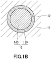
- FIG. 1B schematically shows an example of a cross-section of one of the pores 12 of the porous silica 11.
- the electrolyte 13 forms a first electrolyte layer 130 as a continuous film on the inner surfaces of the plurality of pores 12.
- ions of the electrolyte 13 are oriented regularly.
- the first electrolyte layers 130 respectively provided on the inner surfaces of the plurality of pores 12 are mutually interconnected to form a three-dimensional network.
- a conduction path through which a lithium ion moves is formed near the interface between the porous silica 11 and electrolyte 13, specifically, on the inner surface of the first electrolyte layer 130 provided along the plurality of pores 12.
- the electrolyte 13 may include a second electrolyte layer 140.
- the second electrolyte layer 140 has contact with the inner surface of the first electrolyte layer 130.
- the second electrolyte layer 140 is located in the central portion of the pore 12.
- the first electrolyte layer 130 surrounds the second electrolyte layer 140.
- the second electrolyte layer 140 is a layer in which ions derived from an ionic liquid and lithium salt are oriented irregularly.
- the electrolyte 13 includes an ionic liquid and lithium salt.
- the ionic liquid contains 1-ethyl-3-methylimidazolium bis(trifluoromethanesulfonyl)imide represented by EMI-TFSI.
- the lithium salt is dissolved in EMI-TFSI.
- lithium salt examples include lithium perchlorate (LiClO 4 ), lithium borofluoride (LiBF 4 ), lithium hexafluorophosphate (LiPF 6 ), lithium bis(fluorosulfonyl)imide (Li-FSI), lithium bis(trifluoromethanesulfonyl)imide (Li-TFSI), and lithium bis(pentafluoroethanesulfonyl)imide (Li-BETI).
- Li-FSI lithium bis(fluorosulfonyl)imide
- Li-TFSI lithium bis(trifluoromethanesulfonyl)imide
- Li-BETI lithium bis(pentafluoroethanesulfonyl)imide
- the molar ratio of EMI-TFSI to the porous silica 11 is, for example, larger than 1.5 and less than 2.0. This makes it possible to maintain the solid electrolyte 10 in gel form and achieve high ionic conductivity. If the molar ratio of EMI-TFSI to the porous silica 11 is 1.5 or less or 2.0 or more, it is difficult to achieve high ionic conductivity (for example, 2.8 mS/cm or more). If the molar ratio of EMI-TFSI to the porous silica 11 is too large, it is difficult to obtain the solid electrolyte 10 in gel form.
- the molar ratio of EMI-TFSI to the porous silica 11 may be determined, for example, by element analysis of the solid electrolyte 10. Specifically, the molar ratio of EMI-TFSI to the porous silica 11 can be calculated from the ratio between Si included in the porous silica 11 and an element (for example, N, S, or F) included in EMI-TFSI.
- the element analysis include energy dispersive X-ray (EDX) analysis, electron energy loss spectroscopy (EELS) analysis, Rutherford backscattering spectrometry (RBS) analysis, X-ray photoelectron spectroscopy (XPS) analysis, and Auger electron spectroscopy (AES) analysis.
- FIG. 2 schematically shows an example of a structure of the first electrolyte layer 130 in the vicinity of the inner surface of the pore 12 of the porous silica 11.
- a bis(trifluoromethanesulfonyl)imide ion may be described herein as "TFSI - ion”.
- a 1-ethyl-3-methylimidazolium ion may be described as "EMI + ion”.
- the first electrolyte layer 130 includes a first anion layer 131a, first cation layer 131b, and second anion layer 132a.
- the first anion layer 131a, first cation layer 131b, and second anion layer 132a are arranged on the inner surface of the pore 12 in this order.
- the first anion layer 131a is composed of, for example, a plurality of TFSI - ions. These TFSI - ions adsorb to the porous silica 11.
- the first cation layer 131b is composed of, for example, a plurality of EMI + ions.
- the second anion layer 132a is composed of, for example, anions (for example, TFSI - ions) derived from the lithium salt. These anions are bonded to the plurality of EMI + ions of the first cation layer 131b, respectively.
- the anions of the first anion layer 131a and first cation layer 131b may be anions derived from the ionic liquid or may be anions derived from the lithium salt.
- the form of the anion-cation bonding is, specifically, ionic bonding.
- the lithium ion 132L can easily move over the first electrolyte layer 130 (over the second anion layer 132a) by the following mechanism.
- a ⁇ -electron cloud of the TFSI - ion has large non-locality.
- the EMI + ion has a conjugated ⁇ bond attributed to a five-membered ring.
- a ⁇ -electron cloud of the EMI + ion has large non-locality.
- oxygen of the TFSI - ion is hydrogen-bonded to hydrogen of a silanol group of the porous silica 11 to form the first anion layer 131a.
- the ⁇ -electron cloud of the TFSI - ion is drawn toward the porous silica 11 according to the surface potential of the porous silica 11. This generates polarization charges in the TFSI - ion. Specifically, in the TFSI - ion, a negative polarization charge is generated on the side closer to the porous silica 11 and a positive polarization charge is generated on the side away from the porous silica 11.
- the state in which the TFSI - ion is adsorbed to and arranged on a surface of the porous silica 11 is defined as a first state.
- the state in which the TFSI - ion and EMI + ion are alternately adsorbed to and arranged on a surface of the porous silica 11 is defined as a second state.
- the first state is more stable than the second state. Therefore, the TFSI - ion is preferentially adsorbed to and arranged on a surface of the porous silica 11.
- the EMI + ion is bonded to the first anion layer 131a to form a first cation layer 131b.
- the conjugated ⁇ -electron cloud of the EMI + ion is drawn toward the first anion layer 131a by the positive polarization charge on the surface of the first anion layer 131a.
- This generates polarization charges in the EMI + ion.
- a negative polarization charge is generated on the side closer to the first anion layer 131a and a positive polarization charge is generated on the side away from the first anion layer 131a.
- the TFSI - ion is bonded to the first cation layer 131b to form a second anion layer 132a.
- the ⁇ -electron cloud of the TFSI - ion is drawn toward the first cation layer 131b by the positive polarization charge on the surface of the first cation layer 131b.
- This generates polarization charges in the TFSI - ion. Specifically, in the TFSI - ion, a negative polarization charge is generated on the side closer to the first cation layer 131b and a positive polarization charge is generated on the side away from the first cation layer 131b.
- the positive polarization charge on the surface of the second anion layer 132a can weaken the Coulomb interaction between the TFSI - ion of the second anion layer 132a and the lithium ion 132L. This is inferred to make it easy for the lithium ion 132L to move over the second anion layer 132a.
- the structure of the electrolyte 13 can be estimated in the following manner.
- a molecular vibration mode is examined by Fourier-transform infrared (FT-IR) spectroscopic analysis or Raman analysis. This allows to estimate that the ion of the electrolyte is bonded to silica. Additionally, observation by differential scanning calorimetry (DSC) of no peak or a small peak at a change from a liquid phase to a solid phase confirms the presence of the first electrolyte layer 130 already in the solid phase.
- FT-IR Fourier-transform infrared
- Raman analysis Raman analysis
- FIG. 3 schematically shows another example of the structure of the first electrolyte layer.
- ions respectively constituting layers of a first electrolyte layer 130a are not bonded in one-to-one correspondence.
- the ions respectively constituting the layers of the first electrolyte layer 130a may be bonded to each other depending on the molar ratio between EMI-TFSI and the lithium salt.
- FIG. 4 schematically shows yet another example of the structure of the first electrolyte layer.
- a first electrolyte layer 130b includes the structure described with reference to FIG. 2 and further includes a second cation layer 132b and third anion layer 133a.
- the second cation layer 132b and third anion layer 133a are arranged in this order on the second anion layer 132a.
- the number of layers included in the first electrolyte layer is not particularly limited.
- the first electrolyte layer includes a plurality of anion layers, at least one of these anion layers includes the TFSI - ion.
- the first electrolyte layer includes a plurality of cation layers, at least one of these cation layers includes the EMI + ion.
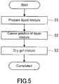
- the production method shown in FIG. 5 includes a step S1 of preparing a liquid mixture, step S2 of forming a gel mixture from the liquid mixture, and step S3 of drying the gel mixture.
- the solid electrolyte 10 described with reference to FIG. 1A can be produced efficiently by a sol-gel process.
- a silicon alkoxide, EMI-TFSI, a lithium salt, water, and an organic solvent are mixed.
- the silicon alkoxide, EMI-TFSI, the lithium salt, water, and the organic solvent are placed in a container and mixed.
- silicon alkoxide examples include tetraethyl orthosilicate (TEOS), tetramethyl orthosilicate (TMOS), and substitution products thereof.
- TEOS tetraethyl orthosilicate
- TMOS tetramethyl orthosilicate
- One silicon alkoxide or two or more silicon alkoxides selected from these silicon alkoxides can be used.
- the boiling point of TEOS is higher than the boiling point of TMOS. Since TEOS is unlikely to volatile in the preparation of the liquid mixture, the use of TEOS as a raw material makes it possible to precisely control the amount of silica obtained at the end.
- lithium salt examples include the various materials described previously.
- Water is required to hydrolyze the silicon alkoxide, and is, for example, deionized water.
- the organic solvent is required to allow the silicon alkoxide, EMI-TFSI, the lithium salt, and water to be uniformly mixed, and is, for example, an alcohol.
- the alcohol include methanol, ethanol, isopropanol, and 1-methoxy-2-propanol (PGME).
- PGME 1-methoxy-2-propanol
- the volume of the organic solvent may be, for example, 1/2 or more of and 3 times or less the sum of the volumes of the silicon alkoxide, EMI-TFSI, the lithium salt, and water. This makes it possible to mix the hydrophilic and hydrophobic materials appropriately. An increase in frequency of collision between siloxane monomers yielded from the silicon alkoxide can accelerate gelation.
- the liquid mixture may contain another material.
- a gel mixture is formed by gelation of the liquid mixture.
- the container of the liquid mixture is sealed and stored at room temperature (25°C, ambient temperature) for about 4 to 23 days, during which the liquid mixture turns into a wet gel mixture.
- the time required for the gelation can be controlled by the amount of water added, amount of the organic solvent added, and storage temperature.
- TEOS is hydrolyzed to form silanol.
- silanol undergoes dehydration polycondensation to form a siloxane monomer.
- a plurality of siloxane molecules undergo dehydration polycondensation to form a siloxane polymer.
- the siloxane polymer forms a three-dimensional network to cause gelation of the liquid mixture.
- the proportion of EMI-TFSI in the liquid mixture is too high, the formation of the siloxane network is difficult and the liquid mixture is unlikely to gelate.
- the present inventors have discovered that even when the proportion of EMI-TFSI is high, the gelation is achieved by increasing water in the liquid mixture to an amount greater than the amount of water in a conventional method.
- the gel mixture is dried.
- the solid electrolyte 10 can thus be obtained.
- the gel mixture is dried, for example, using a vacuum dryer for 48 to 72 hours under the conditions of a pressure of 0.1 to 200 Pa and a temperature of 15 to 150°C (ambient temperature).
- a pre-drying process may be carried out before the vacuum drying step to reduce occurrence of bumping and generation of air bubbles during the vacuum drying.
- the gel mixture is heated, for example, using a hot plate provided on a local exhaust system for 24 to 96 hours under the conditions of atmospheric pressure and a temperature of 15 to 90°C (surface temperature of the hot plate). Most of water and the organic solvent contained in the gel mixture can be evaporated by the pre-drying process.
- FIG. 6 schematically shows an example of a cross-sectional structure of an electrode 20 according to a second embodiment.
- the electrode 20 is disposed on a current collector 21.
- the electrode 20 includes an electrode active material, conductive agent, and solid electrolyte.
- the electrode 20 includes active material particles 22, conductive agent particles 23, and a solid electrolyte 24.
- the active material particles 22 are embedded in a matrix of the solid electrolyte 24 to be fixed.
- the conductive agent particles 23 are also embedded in the matrix of the solid electrolyte 24 to be fixed.
- the shapes of the particles 22 and 23 are not particularly limited.
- the current collector 21 is made of a conductive material.
- the conductive material include metals, conductive oxides, conductive nitrides, conductive carbides, conductive borides, and conductive resins.
- the solid electrolyte 10 described in the first embodiment can be used as the solid electrolyte 24. Since the solid electrolyte 10 of the present disclosure has high ionic conductivity, the electrode 20 having excellent electrical characteristics can be obtained by the use of the solid electrolyte 10.
- the active material particles 22 (first particles) and conductive agent particles 23 (second particles) are fixed in the matrix of the solid electrolyte 24.
- the electrode 20 can reliably exercise the excellent electrical characteristics attributable to the high ionic conductivity of the solid electrolyte 24.
- examples of the positive electrode active material include a lithium-containing transition metal oxide, vanadium oxide, chromium oxide, and lithium-containing transition metal sulfide.
- examples of the lithium-containing transition metal oxide include LiCoO 2 , LiNiO 2 , LiMnO 2 , LiMn 2 O 4 , LiNiCoMnO 2 , LiNiCoO 2 , LiCoMnO 2 , LiNiMnO 2 , LiNiCoMnO 4 , LiMnNiO 4 , LiMnCoO 4 , LiNiCoAlO 2 , LiNiPO 4 , LiCoPO 4 , LiMnPO 4 , LiFePO 4 , Li 2 NiSiO 4 , Li 2 CoSiO 4 , Li 2 MnSiO 4 , Li 2 FeSiO 4 , LiNiBO 3 , LiCoBO 3 , LiMnBO 3 , and LiFePO 4 , Li 2 NiSiO 4 , Li
- examples of the negative electrode active material include a metal, semimetal, oxide, nitride, and carbon.
- the metal and semimetal include lithium, silicon, amorphous silicon, aluminum, silver, tin, antimony, and their alloys.
- the oxide include Li 4 Ti 5 O 12 , Li 2 SrTi 6 O 14 , TiO 2 , Nb 2 O 5 , SnO 2 , Ta 2 O 5 , WO 2 , WO 3 , Fe 2 O 3 , CoO, MoO 2 , SiO, SnBPO 6 , and their mixtures.
- Examples of the nitride include LiCoN, Li 3 FeN 2 , Li 7 MnN 4 , and their mixtures.
- Examples of the carbon include graphite, graphene, hard carbon, carbon nanotube, and their mixtures.
- One negative electrode active material or two or more negative electrode active materials selected from these negative electrode active materials can be used.
- the conductive agent is, for example, a conductive carbon.
- the conductive carbon include carbon black, fibrous carbon, graphite, ketjen black, and acetylene black.
- One conductive agent or two or more conductive agents selected from these conductive agents can be used.
- the conductive agent contributes to a sufficient reduction in the internal resistance of the electrode 20.
- the electrode 20 may further include a binder.
- the binder include carboxymethyl cellulose (CMC) and styrene-butadiene rubber (SBR).
- CMC carboxymethyl cellulose
- SBR styrene-butadiene rubber
- One binder or two or more binders selected from these binders can be used.
- the binder is effective in maintaining the shape of the electrode 20.
- a liquid mixture containing the active material particles is prepared.
- the step S11 may include a sub-step S111 and sub-step S112.
- a precursor liquid is prepared by mixing, for example, EMI-TFSI, the lithium salt, water, the organic solvent, and active material particles.
- silicon alkoxide is mixed into the precursor liquid.
- a liquid mixture containing the active material particles can thus be obtained.
- silicon alkoxide is dropped into a container of the precursor liquid.
- the step S11 is the same step as the step S1 of the first embodiment, except that the active material particles are added to the liquid mixture.
- a step S12 the active material particles coated with a solid electrolyte is formed.
- the operations same as those in the step S2 and step S3 of the first embodiment are carried out. Since the liquid mixture contains the active material particles, the gelation of the liquid mixture forms a gel mixture coating at least a portion of the surface of each active material particle. The active material particles coated with the gel mixture are dried to obtain the active material particles coated with the solid electrolyte.
- a slurry containing the coated active material particles is prepared.
- the coated active material particles and conductive agent particles are added to an electrolyte solution or a solvent, which are then mixed.
- the slurry for producing the electrode can thus be obtained.
- a binder may be added to the slurry, if necessary.
- the conductive agent may be added to the liquid mixture beforehand in the step S11.
- the electrolyte solution used for the formation of the slurry include an electrolyte solution containing a lithium salt and carbonate ester.
- the carbonate ester include chain carbonates, cyclic carbonates, and their mixtures.
- the electrolyte solution can be obtained, for example, by dissolving LiPF 6 at a concentration of 1 mol/liter in a mixed solvent containing ethylene carbonate and diethyl carbonate at a volume ratio of 1:1.
- the solvent used for the preparation of the slurry include water and an organic solvent.
- the organic solvent include N-methylpyrrolidone (NMP).
- a step S14 the slurry is applied to a current collector to form a coating film.
- the method for applying the slurry is not particularly limited.
- the slurry is applied to the current collector, for example, by blade coating.
- the coating film formed on the current collector is dried.
- the dried coating film may be extended by applying pressure so as to obtain the electrode 20 having a certain volume filling rate.
- the electrode 20 can thus be obtained.
- the coating film is dried, for example, using a vacuum dryer for 4 to 12 hours under the conditions of a pressure of 0.1 to 200 Pa and a temperature of 80 to 150°C (ambient temperature).
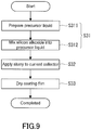
- a liquid mixture is prepared.
- the step S21 is the same step as, for example, the step S1 of the first embodiment.
- an electrode layer is formed on a current collector.
- the electrode layer can be obtained by applying a slurry containing the active material particles and conductive agent particles to the current collector and drying the resultant coating film.
- the slurry may be prepared by adding an electrolyte solution or an organic solvent to the active material particles and conductive agent particles and mixing the resultant mixture.
- the operations same as those in the step S14 and step S15 described with reference to FIG. 7 may be carried out.
- the step S21 is independent of the step S22.
- the order of the step S21 and step S22 is not particularly limited.
- the liquid mixture is impregnated into the electrode layer.
- the liquid mixture may be dropped on the electrode layer or the electrode layer may be immersed in the liquid mixture.
- the liquid mixture may partially undergo gelation before the impregnation of the electrode layer. For example, when the liquid mixture prepared is stored at room temperature for several days, the liquid mixture slightly undergoes gelation. Such a liquid mixture may be impregnated into the electrode layer.
- a step S24 the active material particles coated with a solid electrolyte is formed.
- the liquid mixture impregnated into the electrode layer undergoes gelation, and the resultant gel mixture is dried.
- the operations same as those in the step S2 and step S3 of the first embodiment are carried out.
- the electrode 20 can thus be obtained.
- a slurry containing the active material particles is prepared.
- the step S31 may include a sub-step S311 and sub-step S312.
- the sub-step S311 for example, EMI-TFSI, the lithium salt, water, the organic solvent, active material particles, conductive additive particles, and binder are mixed to prepare a precursor liquid.
- the silicon alkoxide is mixed in the precursor liquid.
- the slurry for producing the electrode can thus be obtained.
- the silicon alkoxide is, for example, dropped into a container of the precursor liquid.
- a step S32 the slurry is applied to a current collector to form a coating film.
- the method of applying the slurry is not particularly limited.
- the slurry is applied to the current collector, for example, by blade coating.
- a step S33 the coating film formed on the current collector is dried.
- the hydrolysis reaction and dehydration polycondensation reaction previously described progress by the drying of the coating film, resulting in formation of a matrix that is a solid electrolyte around the active material particles and conductive additive particles.
- the coating film may be stored at room temperature for a certain period of time (for example, 4 to 23 days) and subsequently dried under certain conditions.
- the coating film is dried, for example, using a vacuum dryer for 48 to 72 hours under the conditions of a pressure of 0.1 to 200 Pa and a temperature of 15 to 150°C (ambient temperature).
- the dried coating film may be extended by applying pressure so as to obtain the electrode 20 having a certain volume filling rate. The electrode 20 can thus be obtained.
- FIG. 10 schematically shows an example of a cross-sectional structure of a power storage device 30 according to a third embodiment.
- the power storage device 30 includes a current collector 31, positive electrode 32, solid electrolyte 33, negative electrode 34, and current collector 35.
- the current collector 21 described in the second embodiment can be used as the current collectors 31 and 35.
- the positive electrode 32 includes, for example, the positive electrode active material described in the second embodiment.
- the negative electrode 34 includes, for example, the negative electrode active material described in the second embodiment.
- the solid electrolyte 33 is disposed between the positive electrode 32 and negative electrode 34.
- the solid electrolyte 10 described in the first embodiment can be used as the solid electrolyte 33. Since the solid electrolyte 10 of the present disclosure has high ionic conductivity, the power storage device 30 having excellent electrical characteristics can be obtained with the use of the solid electrolyte 10.
- FIG. 11 shows an example of a cross-sectional structure of a power storage device 40 according to a fourth embodiment.
- the power storage device 40 includes a current collector 41, positive electrode 42, solid electrolyte 43, negative electrode 44, and current collector 45.
- the current collector 21 described in the second embodiment can be used as the current collectors 41 and 45.
- the electrode 20 described in the second embodiment can be used as the positive electrode 42.
- the negative electrode 44 includes, for example, the negative electrode active material described in the second embodiment.
- the solid electrolyte 43 is disposed between the positive electrode 42 and negative electrode 44.
- the solid electrolyte 10 described in the first embodiment can be used as the solid electrolyte 43.
- the solid electrolyte 43 may be a different solid electrolyte.
- Examples of the different solid electrolyte include an inorganic solid electrolyte and polymer electrolyte.
- Examples of the inorganic solid electrolyte include an inorganic oxide and inorganic sulfide.
- Examples of the inorganic oxide include LiPON, LiAlTi(PO 4 ) 3 , LiAlGeTi(PO 4 ) 3 , LiLaTiO, LiLaZrO, Li 3 PO 4 , Li 2 SiO 2 , Li 3 SiO 4 , Li 3 VO 4 , Li 4 SiO 4 -Zn 2 SiO 4 , Li 4 GeO 4 -Li 2 GeZnO 4 , Li 2 GeZnO 4 -Zn 2 GeO 4 , and Li 4 GeO 4 -Li 3 VO 4 .
- Examples of the inorganic sulfide include Li 2 S-P 2 S 5 , Li 2 S-P 2 S 5 -LiI, Li 2 S-P 2 S 5 -Li 2 O-LiI, Li 2 S-SiS 2 , Li 2 S-SiS 2 -LiI, Li 2 S-SiS 2 -LiBr, Li 2 S-SiS 2 -LiCl, Li 2 S-SiS 2 -B 2 S 3 -LiI, Li 2 S-SiS 2 -P 2 S 5 -LiI, Li 2 S-B 2 S 3 , Li 2 S-P 2 S 5 -GeS, Li 2 S-P 2 S 5 -ZnS, Li 2 S-P 2 S 5 -GaS, Li 2 S-GeS 2 , Li 2 S-SiS 2 -Li 3 PO 4 , Li 2 S-SiS 2 -LiPO, Li 2 S-SiS 2 -Li
- the solid electrolyte 43 may be omitted when sufficient electron insulation properties can be ensured in the power storage device 40.
- a liquid mixture is applied to a surface of the electrode 20 to form a coating film.
- a thin solid electrolyte layer can be formed on the electrode 20 by gelation and drying of the coating film. When this thin layer is sufficient to prevent a short circuit between the positive electrode and negative electrode, no solid electrolyte serving as a separator is separately needed.
- the solid electrolyte-including electrode of the present disclosure is employed only as the positive electrode 42.
- FIG. 12 shows an example of a cross-sectional structure of a power storage device 50 according to a fifth embodiment.
- the power storage device 50 includes a current collector 51, positive electrode 52, solid electrolyte 53, negative electrode 54, and current collector 55.
- the current collector 21 described in the second embodiment can be used as the current collectors 51 and 55.
- the electrode 20 described in the second embodiment can be used as the positive electrode 52 and negative electrode 54.
- the solid electrolyte 53 is disposed between the positive electrode 52 and negative electrode 54.
- the solid electrolyte 10 described in the first embodiment can be used as the solid electrolyte 53.
- the solid electrolyte 53 may be a different solid electrolyte.
- the solid electrolyte-including electrode of the present disclosure is employed as both the positive electrode 52 and negative electrode 54.
- the solid electrolyte-including electrode of the present disclosure may be employed only as the negative electrode 54.
- the electrode 20 of the present disclosure is used as at least one selected from the positive electrode and negative electrode.
- the electrode 20 includes the solid electrolyte 10 of the present disclosure. Since the solid electrolyte 10 has high ionic conductivity, a power storage device having excellent electrical characteristics can be obtained by the use of the solid electrolyte 10.
- EMI-TFSI EMI-TFSI
- Li-TFSI 0.5 ml of TEOS
- PGME 1.5 ml
- PGME 0.5 ml
- water 0.5 ml
- the samples were sealed in the respective glass containers and stored at room temperature (25°C).
- the samples turned into wet gel mixtures in 10 to 17 days.
- FIG. 13 shows a relationship between the molar ratio of EMI-TFSI to TEOS and the ionic conductivity. Assuming that all Si atoms contained in TEOS form a skeleton of porous silica, the molar ratio of EMI-TFSI to TEOS is equal to the molar ratio of EMI-TFSI to the porous silica.
- a non-aqueous electrolyte solution containing Li-TFSI and EMI-TFSI was prepared as Reference Example.
- the molar ratio of Li-TFSI to EMI-TFSI was 0.33.
- the ionic conductivity of this non-aqueous electrolyte solution was 2.8 mS/cm.
- the ionic conductivity increases with increasing molar ratio of EMI-TFSI to TEOS.
- the molar ratio of EMI-TFSI to TEOS exceeds 1.5
- the ionic conductivity of the solid electrolyte exceeds the ionic conductivity of the non-aqueous electrolyte solution and reached about 3.0 mS/cm.
- the techniques of the present disclosure are useful for power storage devices such as lithium-ion secondary batteries.
Abstract
Description
- The present disclosure relates to a solid electrolyte, electrode, power storage device, and method for producing solid electrolytes.
- All-solid-state lithium secondary batteries have recently been under development as next-generation batteries. It has been desired to improve the ionic conductivity of solid electrolytes used in power storage devices such as all-solid-state lithium secondary batteries.
-
Patent Literature 1 discloses a method for producing solid electrolytes by a sol-gel process using a liquid mixture containing an ionic liquid, lithium salt, and silica precursor. - Patent Literature 1:
JP 2012-518248 A - The present disclosure provides a new solid electrolyte with high ionic conductivity.
- The present disclosure provides a solid electrolyte including:
- porous silica having a plurality of pores interconnected mutually; and
- an electrolyte coating inner surfaces of the plurality of pores, wherein the electrolyte includes 1-ethyl-3-methylimidazolium
- The present disclosure can provide a new solid electrolyte with high ionic conductivity.
-
-
FIG. 1A schematically shows an example of a cross-sectional structure of a solid electrolyte according to a first embodiment. -
FIG. 1B schematically shows a cross-section of a pore of porous silica. -
FIG. 2 schematically shows an example of a structure of a first electrolyte layer. -
FIG. 3 schematically shows another example of the structure of the first electrolyte layer. -
FIG. 4 schematically shows yet another example of the structure of the first electrolyte layer. -
FIG. 5 is a flowchart showing an example of a method for producing the solid electrolyte according to the first embodiment. -
FIG. 6 schematically shows an example of a cross-sectional structure of an electrode according to a second embodiment. -
FIG. 7 is a flowchart showing an example of a method for producing the electrode according to the second embodiment. -
FIG. 8 is a flowchart showing another example of the method for producing the electrode according to the second embodiment. -
FIG. 9 is a flowchart showing yet another example of the method for producing the electrode according to the second embodiment. -
FIG. 10 schematically shows an example of a cross-sectional structure of a power storage device according to a third embodiment. -
FIG. 11 schematically shows an example of a cross-sectional structure of a power storage device according to a fourth embodiment. -
FIG. 12 schematically shows an example of a cross-sectional structure of a power storage device according to a fifth embodiment. -
FIG. 13 is a graph showing the relationship between the molar ratio of EMI-TFSI to TEOS and the ionic conductivity. -
FIG. 14A schematically shows a state of the inner surface of pores of porous silica in the case where the molar ratio of EMI-TFSI to TEOS is too small. -
FIG. 14B schematically shows a state of the inner surface of pores of porous silica in the case where the molar ratio of EMI-TFSI to TEOS is sufficiently large. - (Summary of one aspect according to the present disclosure)
- A solid electrolyte according to a first aspect of the present disclosure includes:
- porous silica having a plurality of pores interconnected mutually; and
- an electrolyte coating inner surfaces of the plurality of pores, wherein the electrolyte includes 1-ethyl-3-methylimidazolium
- According to the first aspect, the solid electrolyte can be maintained in gel form and high ionic conductivity can be achieved.
- According to a second aspect of the present disclosure, for example, the lithium salt of the solid electrolyte according to the first aspect may include lithium bis(trifluoromethanesulfonyl)imide. With the use of Li-TFSI, a solid electrolyte having excellent cycle characteristics, rate characteristics, and low-temperature characteristics can be obtained.
- According to a third aspect of the present disclosure, for example, the electrolyte of the solid electrolyte according to the second aspect may include a first electrolyte layer having contact with the inner surfaces of the plurality of pores, the first electrolyte layer may include a first anion layer, a first cation layer, and a second anion layer, the first anion layer may include a plurality of first bis(trifluoromethanesulfonyl)imide ions adsorbed to the inner surfaces of the plurality of pores of the porous silica, the first cation layer may include a plurality of 1-ethyl-3-methylimidazolium ions ionically bonded to the plurality of first bis(trifluoromethanesulfonyl)imide ions respectively, and the second anion layer may include a plurality of second bis(trifluoromethanesulfonyl)imide ions ionically bonded to the plurality of 1-ethyl-3-methylimidazolium ions respectively. It is inferred that according to the third aspect, a lithium ion is able to move easily over the first electrolyte layer.
- According to a fourth aspect of the present disclosure, for example, in any one of the solid electrolytes according to the first to third aspects, the molar ratio of the EMI-TFSI to the porous silica may be 1.7 or more and 1.8 or less. According to the fourth aspect, a solid electrolyte with high ionic conductivity can be reliably obtained.
- According to a fifth aspect of the present disclosure, for example, in the solid electrolyte according to any one of the first to fourth aspects, the porous silica may form a single layer, and an outer boundary of the solid electrolyte may be defined by the porous silica. Such a configuration allows easy handling of the solid electrolyte and easy application of the solid electrolyte to, for example, a power storage device.
- An electrode according to a sixth aspect of the present disclosure includes:
- the solid electrolyte according to any one of the first to fifth aspects; and
- an electrode active material.
- According to the sixth aspect, an electrode having excellent electrical characteristics can be obtained.
- In a seventh aspect of the present disclosure, for example, the electrode according to the sixth aspect may further include at least one selected from a conductive agent and a binder. The conductive agent contributes to a sufficient reduction in the internal resistance of the electrode. The binder serves to fix particles of the electrode active material to each other. When the particles of the electrode active material are fixed to each other, occurrence of a gap due to expansion and shrinkage of the particles of the electrode active material is reduced. This reduces a decrease in the discharged capacity of a battery including the electrode.
- According to an eighth aspect of the present disclosure, for example, the electrode according to the sixth or seventh aspect may further include a conductive agent, and a plurality of first particles made of the electrode active material and a plurality of second particles made of the conductive agent may be fixed in a matrix of the solid electrolyte. According to the eighth aspect, the electrode can reliably exercise the excellent electrical characteristics attributable to the high ionic conductivity of the solid electrolyte may be reliably exhibited.
- A power storage device according to a ninth aspect of the present disclosure includes:
- a positive electrode;
- a negative electrode; and
- the solid electrolyte according to any one of the first to fifth aspects.
- According to the ninth aspect, a power storage device having excellent electrical characteristics can be obtained.
- A power storage device according to a tenth aspect of the present disclosure includes:
- a positive electrode; and
- a negative electrode, wherein
- at least one selected from the positive electrode and the negative electrode is the electrode according to any one of the sixth to eighth aspects.
- According to the tenth aspect, a power storage device having excellent electrical characteristics can be obtained.
- A method for producing solid electrolytes according to an eleventh aspect of the present disclosure includes:
- mixing a silicon alkoxide, 1-ethyl-3-methylimidazolium bis(trifluoromethanesulfonyl)imide, a lithium salt, water, and an organic solvent to prepare a liquid mixture;
- causing gelation of the liquid mixture to form a gel mixture; and
- drying the gel mixture to form a solid electrolyte.
- According to the eleventh aspect, the solid electrolyte of the present disclosure can be produced efficiently.
- According to a twelfth aspect of the present disclosure, for example, in the method for producing solid electrolytes according to the eleventh aspect, the silicon alkoxide may include at least one selected from tetraethyl orthosilicate and a substituted tetraethyl orthosilicate. Since tetraethyl orthosilicate is unlikely to volatile in the preparation of the liquid mixture, the use of tetraethyl orthosilicate as a raw material makes it possible to precisely control the amount of silica obtained at the end.
- Hereinafter, an embodiment of the present invention will be described with reference to the drawings. The present invention is not limited to the following embodiment.
-
FIG. 1A schematically shows an example of a cross-sectional structure of asolid electrolyte 10 according to a first embodiment. Thesolid electrolyte 10 includesporous silica 11 and anelectrolyte 13. Theporous silica 11 has a plurality ofpores 12 interconnected mutually. The plurality ofpores 12 are what are called continuous pores. Incidentally, the plurality ofpores 12 may include an isolated pore. Theelectrolyte 13 coats the inner surfaces of thesepores 12. Theelectrolyte 13 may at least partially fill the interior of the plurality ofpores 12, or may completely fill the interior of the plurality ofpores 12. - The term "solid" as used herein refers to being in solid state as a whole system at room temperature. Partial inclusion of a liquid is not excluded. Gels, for example, are "solid".
- The
porous silica 11 is, for example, mesoporous silica. Theporous silica 11 may have a porosity in the range of 25% to 90%. The diameter of eachpore 12 of theporous silica 11 is, for example, in the range of 2 nm to 50 nm. The diameters of thepores 12 may be measured, for example, by the following method. Thesolid electrolyte 10 is immersed in an organic solvent to dissolve theelectrolyte 13 in the organic solvent. Theelectrolyte 13 is then removed by supercritical drying, followed by measurement of the specific surface area of theporous silica 11 by the BET method. From the result of the measurement, the porosity and the respective diameters of the pores 12 (micropore distribution) can be calculated. Alternatively, the porosity and the diameters of thepores 12 can be determined by preparing a thin piece of thesolid electrolyte 10 by focused ion beam (FIB) and observing the thin piece of thesolid electrolyte 10 with a transmission electron microscope (TEM). - In the present embodiment, the
porous silica 11 forms a single layer. The layer of theporous silica 11 may be self-supporting. The outer boundary of thesolid electrolyte 10 is defined by theporous silica 11. Such a configuration allows easy handling of thesolid electrolyte 10 and easy application of thesolid electrolyte 10 to, for example, a power storage device. -
FIG. 1B schematically shows an example of a cross-section of one of thepores 12 of theporous silica 11. As shown inFIG. 1B , theelectrolyte 13 forms afirst electrolyte layer 130 as a continuous film on the inner surfaces of the plurality ofpores 12. In thefirst electrolyte layer 130, ions of theelectrolyte 13 are oriented regularly. The first electrolyte layers 130 respectively provided on the inner surfaces of the plurality ofpores 12 are mutually interconnected to form a three-dimensional network. As indicated by a dotted line L inFIG. 1A , a conduction path through which a lithium ion moves is formed near the interface between theporous silica 11 andelectrolyte 13, specifically, on the inner surface of thefirst electrolyte layer 130 provided along the plurality ofpores 12. - As shown in
FIG. 1B , theelectrolyte 13 may include asecond electrolyte layer 140. Thesecond electrolyte layer 140 has contact with the inner surface of thefirst electrolyte layer 130. Thesecond electrolyte layer 140 is located in the central portion of thepore 12. Thefirst electrolyte layer 130 surrounds thesecond electrolyte layer 140. Thesecond electrolyte layer 140 is a layer in which ions derived from an ionic liquid and lithium salt are oriented irregularly. - The
electrolyte 13 includes an ionic liquid and lithium salt. The ionic liquid contains 1-ethyl-3-methylimidazolium bis(trifluoromethanesulfonyl)imide represented by EMI-TFSI. The lithium salt is dissolved in EMI-TFSI. - Examples of the lithium salt include lithium perchlorate (LiClO4), lithium borofluoride (LiBF4), lithium hexafluorophosphate (LiPF6), lithium bis(fluorosulfonyl)imide (Li-FSI), lithium bis(trifluoromethanesulfonyl)imide (Li-TFSI), and lithium bis(pentafluoroethanesulfonyl)imide (Li-BETI). One lithium salt or two or more lithium salts selected from these lithium salts can be used. The lithium salt is, for example, lithium bis(trifluoromethanesulfonyl)imide (Li-TFSI). With the use of Li-TFSI, a solid electrolyte having excellent rate characteristics can be obtained.
- The molar ratio of EMI-TFSI to the
porous silica 11 is, for example, larger than 1.5 and less than 2.0. This makes it possible to maintain thesolid electrolyte 10 in gel form and achieve high ionic conductivity. If the molar ratio of EMI-TFSI to theporous silica 11 is 1.5 or less or 2.0 or more, it is difficult to achieve high ionic conductivity (for example, 2.8 mS/cm or more). If the molar ratio of EMI-TFSI to theporous silica 11 is too large, it is difficult to obtain thesolid electrolyte 10 in gel form. - The molar ratio of EMI-TFSI to the
porous silica 11 may be determined, for example, by element analysis of thesolid electrolyte 10. Specifically, the molar ratio of EMI-TFSI to theporous silica 11 can be calculated from the ratio between Si included in theporous silica 11 and an element (for example, N, S, or F) included in EMI-TFSI. Examples of the element analysis include energy dispersive X-ray (EDX) analysis, electron energy loss spectroscopy (EELS) analysis, Rutherford backscattering spectrometry (RBS) analysis, X-ray photoelectron spectroscopy (XPS) analysis, and Auger electron spectroscopy (AES) analysis. -
FIG. 2 schematically shows an example of a structure of thefirst electrolyte layer 130 in the vicinity of the inner surface of thepore 12 of theporous silica 11. A bis(trifluoromethanesulfonyl)imide ion may be described herein as "TFSI- ion". A 1-ethyl-3-methylimidazolium ion may be described as "EMI+ ion". - In the example shown in
FIG. 2 , thefirst electrolyte layer 130 includes afirst anion layer 131a,first cation layer 131b, andsecond anion layer 132a. Thefirst anion layer 131a,first cation layer 131b, andsecond anion layer 132a are arranged on the inner surface of thepore 12 in this order. There is alithium ion 132L over thefirst electrolyte layer 130. Thefirst anion layer 131a is composed of, for example, a plurality of TFSI- ions. These TFSI- ions adsorb to theporous silica 11. Thefirst cation layer 131b is composed of, for example, a plurality of EMI+ ions. These EMI+ ions are bonded to the plurality of TFSI- ions of thefirst anion layer 131a, respectively. Thesecond anion layer 132a is composed of, for example, anions (for example, TFSI- ions) derived from the lithium salt. These anions are bonded to the plurality of EMI+ ions of thefirst cation layer 131b, respectively. The anions of thefirst anion layer 131a andfirst cation layer 131b may be anions derived from the ionic liquid or may be anions derived from the lithium salt. The form of the anion-cation bonding is, specifically, ionic bonding. - It is inferred that in the
solid electrolyte 10, thelithium ion 132L can easily move over the first electrolyte layer 130 (over thesecond anion layer 132a) by the following mechanism. - The TFSI- ion has a π bond attributed to an S=O bond. A π-electron cloud of the TFSI- ion has large non-locality. The EMI+ ion has a conjugated π bond attributed to a five-membered ring. A π-electron cloud of the EMI+ ion has large non-locality.
- First, oxygen of the TFSI- ion is hydrogen-bonded to hydrogen of a silanol group of the
porous silica 11 to form thefirst anion layer 131a. At this moment, the π-electron cloud of the TFSI- ion is drawn toward theporous silica 11 according to the surface potential of theporous silica 11. This generates polarization charges in the TFSI- ion. Specifically, in the TFSI- ion, a negative polarization charge is generated on the side closer to theporous silica 11 and a positive polarization charge is generated on the side away from theporous silica 11. - As shown in
FIG. 2 , the state in which the TFSI- ion is adsorbed to and arranged on a surface of theporous silica 11 is defined as a first state. The state in which the TFSI- ion and EMI+ ion are alternately adsorbed to and arranged on a surface of theporous silica 11 is defined as a second state. According to calculation, the first state is more stable than the second state. Therefore, the TFSI- ion is preferentially adsorbed to and arranged on a surface of theporous silica 11. - Next, the EMI+ ion is bonded to the
first anion layer 131a to form afirst cation layer 131b. At this moment, the conjugated π-electron cloud of the EMI+ ion is drawn toward thefirst anion layer 131a by the positive polarization charge on the surface of thefirst anion layer 131a. This generates polarization charges in the EMI+ ion. Specifically, in the EMI+ ion, a negative polarization charge is generated on the side closer to thefirst anion layer 131a and a positive polarization charge is generated on the side away from thefirst anion layer 131a. - Next, the TFSI- ion is bonded to the
first cation layer 131b to form asecond anion layer 132a. At this moment, the π-electron cloud of the TFSI- ion is drawn toward thefirst cation layer 131b by the positive polarization charge on the surface of thefirst cation layer 131b. This generates polarization charges in the TFSI- ion. Specifically, in the TFSI- ion, a negative polarization charge is generated on the side closer to thefirst cation layer 131b and a positive polarization charge is generated on the side away from thefirst cation layer 131b. - The positive polarization charge on the surface of the
second anion layer 132a can weaken the Coulomb interaction between the TFSI- ion of thesecond anion layer 132a and thelithium ion 132L. This is inferred to make it easy for thelithium ion 132L to move over thesecond anion layer 132a. - The structure of the
electrolyte 13 can be estimated in the following manner. A molecular vibration mode is examined by Fourier-transform infrared (FT-IR) spectroscopic analysis or Raman analysis. This allows to estimate that the ion of the electrolyte is bonded to silica. Additionally, observation by differential scanning calorimetry (DSC) of no peak or a small peak at a change from a liquid phase to a solid phase confirms the presence of thefirst electrolyte layer 130 already in the solid phase. -
FIG. 3 schematically shows another example of the structure of the first electrolyte layer. As shown inFIG. 3 , ions respectively constituting layers of afirst electrolyte layer 130a are not bonded in one-to-one correspondence. The ions respectively constituting the layers of thefirst electrolyte layer 130a may be bonded to each other depending on the molar ratio between EMI-TFSI and the lithium salt. -
FIG. 4 schematically shows yet another example of the structure of the first electrolyte layer. As shown inFIG. 4 , afirst electrolyte layer 130b includes the structure described with reference toFIG. 2 and further includes asecond cation layer 132b andthird anion layer 133a. Thesecond cation layer 132b andthird anion layer 133a are arranged in this order on thesecond anion layer 132a. There is thelithium ion 132L over thethird anion layer 133a. - As can be understood from
FIG. 2 andFIG. 4 , the number of layers included in the first electrolyte layer is not particularly limited. When the first electrolyte layer includes a plurality of anion layers, at least one of these anion layers includes the TFSI- ion. When the first electrolyte layer includes a plurality of cation layers, at least one of these cation layers includes the EMI+ ion. - Next, an example of a method for producing the
solid electrolyte 10 will be described with reference toFIG. 5 . - The production method shown in
FIG. 5 includes a step S1 of preparing a liquid mixture, step S2 of forming a gel mixture from the liquid mixture, and step S3 of drying the gel mixture. Thesolid electrolyte 10 described with reference toFIG. 1A can be produced efficiently by a sol-gel process. - In the step S1, a silicon alkoxide, EMI-TFSI, a lithium salt, water, and an organic solvent are mixed. For example, the silicon alkoxide, EMI-TFSI, the lithium salt, water, and the organic solvent are placed in a container and mixed.
- Examples of the silicon alkoxide include tetraethyl orthosilicate (TEOS), tetramethyl orthosilicate (TMOS), and substitution products thereof. One silicon alkoxide or two or more silicon alkoxides selected from these silicon alkoxides can be used. The boiling point of TEOS is higher than the boiling point of TMOS. Since TEOS is unlikely to volatile in the preparation of the liquid mixture, the use of TEOS as a raw material makes it possible to precisely control the amount of silica obtained at the end.
- Examples of the lithium salt include the various materials described previously.
- Water is required to hydrolyze the silicon alkoxide, and is, for example, deionized water.
- The organic solvent is required to allow the silicon alkoxide, EMI-TFSI, the lithium salt, and water to be uniformly mixed, and is, for example, an alcohol. Examples of the alcohol include methanol, ethanol, isopropanol, and 1-methoxy-2-propanol (PGME). One alcohol or two or more alcohols selected from these alcohols can be used.
- The volume of the organic solvent may be, for example, 1/2 or more of and 3 times or less the sum of the volumes of the silicon alkoxide, EMI-TFSI, the lithium salt, and water. This makes it possible to mix the hydrophilic and hydrophobic materials appropriately. An increase in frequency of collision between siloxane monomers yielded from the silicon alkoxide can accelerate gelation.
- The liquid mixture may contain another material.
- In the step S2, a gel mixture is formed by gelation of the liquid mixture. For example, the container of the liquid mixture is sealed and stored at room temperature (25°C, ambient temperature) for about 4 to 23 days, during which the liquid mixture turns into a wet gel mixture. The time required for the gelation can be controlled by the amount of water added, amount of the organic solvent added, and storage temperature.
- Specifically, the following reactions occur. First, TEOS is hydrolyzed to form silanol. Next, two silanol molecules undergo dehydration polycondensation to form a siloxane monomer. Then, a plurality of siloxane molecules undergo dehydration polycondensation to form a siloxane polymer. In this manner, the siloxane polymer forms a three-dimensional network to cause gelation of the liquid mixture.
- When the proportion of EMI-TFSI in the liquid mixture is too high, the formation of the siloxane network is difficult and the liquid mixture is unlikely to gelate. The present inventors have discovered that even when the proportion of EMI-TFSI is high, the gelation is achieved by increasing water in the liquid mixture to an amount greater than the amount of water in a conventional method.
- In the step S3, the gel mixture is dried. The
solid electrolyte 10 can thus be obtained. The gel mixture is dried, for example, using a vacuum dryer for 48 to 72 hours under the conditions of a pressure of 0.1 to 200 Pa and a temperature of 15 to 150°C (ambient temperature). A pre-drying process may be carried out before the vacuum drying step to reduce occurrence of bumping and generation of air bubbles during the vacuum drying. In the pre-drying process, the gel mixture is heated, for example, using a hot plate provided on a local exhaust system for 24 to 96 hours under the conditions of atmospheric pressure and a temperature of 15 to 90°C (surface temperature of the hot plate). Most of water and the organic solvent contained in the gel mixture can be evaporated by the pre-drying process. -
FIG. 6 schematically shows an example of a cross-sectional structure of an electrode 20 according to a second embodiment. InFIG. 6 , the electrode 20 is disposed on acurrent collector 21. The electrode 20 includes an electrode active material, conductive agent, and solid electrolyte. Specifically, the electrode 20 includes active material particles 22,conductive agent particles 23, and asolid electrolyte 24. The active material particles 22 are embedded in a matrix of thesolid electrolyte 24 to be fixed. Theconductive agent particles 23 are also embedded in the matrix of thesolid electrolyte 24 to be fixed. The shapes of theparticles 22 and 23 are not particularly limited. - The
current collector 21 is made of a conductive material. Examples of the conductive material include metals, conductive oxides, conductive nitrides, conductive carbides, conductive borides, and conductive resins. - The
solid electrolyte 10 described in the first embodiment can be used as thesolid electrolyte 24. Since thesolid electrolyte 10 of the present disclosure has high ionic conductivity, the electrode 20 having excellent electrical characteristics can be obtained by the use of thesolid electrolyte 10. - According to the present embodiment, the active material particles 22 (first particles) and conductive agent particles 23 (second particles) are fixed in the matrix of the
solid electrolyte 24. With such a configuration, the electrode 20 can reliably exercise the excellent electrical characteristics attributable to the high ionic conductivity of thesolid electrolyte 24. - When the electrode active material used in the electrode 20 is a positive electrode active material, examples of the positive electrode active material include a lithium-containing transition metal oxide, vanadium oxide, chromium oxide, and lithium-containing transition metal sulfide. Examples of the lithium-containing transition metal oxide include LiCoO2, LiNiO2, LiMnO2, LiMn2O4, LiNiCoMnO2, LiNiCoO2, LiCoMnO2, LiNiMnO2, LiNiCoMnO4, LiMnNiO4, LiMnCoO4, LiNiCoAlO2, LiNiPO4, LiCoPO4, LiMnPO4, LiFePO4, Li2NiSiO4, Li2CoSiO4, Li2MnSiO4, Li2FeSiO4, LiNiBO3, LiCoBO3, LiMnBO3, and LiFeBO3. Examples of the lithium-containing transition metal sulfide include LiTiS2, Li2TiS3, and Li3NbS4. One positive electrode active material or two or more positive electrode active materials selected from these positive electrode active materials can be used.
- When the electrode active material used in the electrode 20 is a negative electrode active material, examples of the negative electrode active material include a metal, semimetal, oxide, nitride, and carbon. Examples of the metal and semimetal include lithium, silicon, amorphous silicon, aluminum, silver, tin, antimony, and their alloys. Examples of the oxide include Li4Ti5O12, Li2SrTi6O14, TiO2, Nb2O5, SnO2, Ta2O5, WO2, WO3, Fe2O3, CoO, MoO2, SiO, SnBPO6, and their mixtures. Examples of the nitride include LiCoN, Li3FeN2, Li7MnN4, and their mixtures. Examples of the carbon include graphite, graphene, hard carbon, carbon nanotube, and their mixtures. One negative electrode active material or two or more negative electrode active materials selected from these negative electrode active materials can be used.
- The conductive agent is, for example, a conductive carbon. Examples of the conductive carbon include carbon black, fibrous carbon, graphite, ketjen black, and acetylene black. One conductive agent or two or more conductive agents selected from these conductive agents can be used. The conductive agent contributes to a sufficient reduction in the internal resistance of the electrode 20.
- The electrode 20 may further include a binder. Examples of the binder include carboxymethyl cellulose (CMC) and styrene-butadiene rubber (SBR). One binder or two or more binders selected from these binders can be used. The binder is effective in maintaining the shape of the electrode 20.
- Next, an example of a method for producing the electrode 20 will be described with reference to
FIG. 7 . - In a step S11, a liquid mixture containing the active material particles is prepared. The step S11 may include a sub-step S111 and sub-step S112. In the sub-step S111, a precursor liquid is prepared by mixing, for example, EMI-TFSI, the lithium salt, water, the organic solvent, and active material particles. In the sub-step S112, silicon alkoxide is mixed into the precursor liquid. A liquid mixture containing the active material particles can thus be obtained. In the sub-step S112, for example, silicon alkoxide is dropped into a container of the precursor liquid. The step S11 is the same step as the step S1 of the first embodiment, except that the active material particles are added to the liquid mixture.
- In a step S12, the active material particles coated with a solid electrolyte is formed. In the step S12, for example, the operations same as those in the step S2 and step S3 of the first embodiment are carried out. Since the liquid mixture contains the active material particles, the gelation of the liquid mixture forms a gel mixture coating at least a portion of the surface of each active material particle. The active material particles coated with the gel mixture are dried to obtain the active material particles coated with the solid electrolyte.
- In a step S13, a slurry containing the coated active material particles is prepared. The coated active material particles and conductive agent particles are added to an electrolyte solution or a solvent, which are then mixed. The slurry for producing the electrode can thus be obtained. A binder may be added to the slurry, if necessary. The conductive agent may be added to the liquid mixture beforehand in the step S11. Examples of the electrolyte solution used for the formation of the slurry include an electrolyte solution containing a lithium salt and carbonate ester. Examples of the carbonate ester include chain carbonates, cyclic carbonates, and their mixtures. The electrolyte solution can be obtained, for example, by dissolving LiPF6 at a concentration of 1 mol/liter in a mixed solvent containing ethylene carbonate and diethyl carbonate at a volume ratio of 1:1. Examples of the solvent used for the preparation of the slurry include water and an organic solvent. Examples of the organic solvent include N-methylpyrrolidone (NMP).
- In a step S14, the slurry is applied to a current collector to form a coating film. The method for applying the slurry is not particularly limited. The slurry is applied to the current collector, for example, by blade coating.
- In a step S15, the coating film formed on the current collector is dried. The dried coating film may be extended by applying pressure so as to obtain the electrode 20 having a certain volume filling rate. The electrode 20 can thus be obtained. The coating film is dried, for example, using a vacuum dryer for 4 to 12 hours under the conditions of a pressure of 0.1 to 200 Pa and a temperature of 80 to 150°C (ambient temperature).
- Next, another example of the method for producing the electrode 20 will be described with reference to
FIG. 8 . - In a step S21, a liquid mixture is prepared. The step S21 is the same step as, for example, the step S1 of the first embodiment.
- In a step S22, an electrode layer is formed on a current collector. The electrode layer can be obtained by applying a slurry containing the active material particles and conductive agent particles to the current collector and drying the resultant coating film. The slurry may be prepared by adding an electrolyte solution or an organic solvent to the active material particles and conductive agent particles and mixing the resultant mixture. In the step S22, the operations same as those in the step S14 and step S15 described with reference to
FIG. 7 may be carried out. - The step S21 is independent of the step S22. The order of the step S21 and step S22 is not particularly limited.
- In a step S23, the liquid mixture is impregnated into the electrode layer. To impregnate the liquid mixture into the electrode layer, the liquid mixture may be dropped on the electrode layer or the electrode layer may be immersed in the liquid mixture. The liquid mixture may partially undergo gelation before the impregnation of the electrode layer. For example, when the liquid mixture prepared is stored at room temperature for several days, the liquid mixture slightly undergoes gelation. Such a liquid mixture may be impregnated into the electrode layer.
- In a step S24, the active material particles coated with a solid electrolyte is formed. The liquid mixture impregnated into the electrode layer undergoes gelation, and the resultant gel mixture is dried. In the step S24, the operations same as those in the step S2 and step S3 of the first embodiment are carried out. The electrode 20 can thus be obtained.
- Next, yet another example of the method for producing the electrode 20 will be described with reference to
FIG. 9 . - In a step S31, a slurry containing the active material particles is prepared. The step S31 may include a sub-step S311 and sub-step S312. In the sub-step S311, for example, EMI-TFSI, the lithium salt, water, the organic solvent, active material particles, conductive additive particles, and binder are mixed to prepare a precursor liquid. In the sub-step S312, the silicon alkoxide is mixed in the precursor liquid. The slurry for producing the electrode can thus be obtained. In the sub-step S312, the silicon alkoxide is, for example, dropped into a container of the precursor liquid.
- In a step S32, the slurry is applied to a current collector to form a coating film. The method of applying the slurry is not particularly limited. The slurry is applied to the current collector, for example, by blade coating.
- In a step S33, the coating film formed on the current collector is dried. The hydrolysis reaction and dehydration polycondensation reaction previously described progress by the drying of the coating film, resulting in formation of a matrix that is a solid electrolyte around the active material particles and conductive additive particles. The coating film may be stored at room temperature for a certain period of time (for example, 4 to 23 days) and subsequently dried under certain conditions. The coating film is dried, for example, using a vacuum dryer for 48 to 72 hours under the conditions of a pressure of 0.1 to 200 Pa and a temperature of 15 to 150°C (ambient temperature). The dried coating film may be extended by applying pressure so as to obtain the electrode 20 having a certain volume filling rate. The electrode 20 can thus be obtained.
-
FIG. 10 schematically shows an example of a cross-sectional structure of apower storage device 30 according to a third embodiment. InFIG. 10 , thepower storage device 30 includes acurrent collector 31,positive electrode 32,solid electrolyte 33,negative electrode 34, andcurrent collector 35. Thecurrent collector 21 described in the second embodiment can be used as thecurrent collectors positive electrode 32 includes, for example, the positive electrode active material described in the second embodiment. Thenegative electrode 34 includes, for example, the negative electrode active material described in the second embodiment. - The
solid electrolyte 33 is disposed between thepositive electrode 32 andnegative electrode 34. Thesolid electrolyte 10 described in the first embodiment can be used as thesolid electrolyte 33. Since thesolid electrolyte 10 of the present disclosure has high ionic conductivity, thepower storage device 30 having excellent electrical characteristics can be obtained with the use of thesolid electrolyte 10. -
FIG. 11 shows an example of a cross-sectional structure of apower storage device 40 according to a fourth embodiment. InFIG. 11 , thepower storage device 40 includes acurrent collector 41,positive electrode 42,solid electrolyte 43,negative electrode 44, andcurrent collector 45. Thecurrent collector 21 described in the second embodiment can be used as thecurrent collectors positive electrode 42. Thenegative electrode 44 includes, for example, the negative electrode active material described in the second embodiment. - The
solid electrolyte 43 is disposed between thepositive electrode 42 andnegative electrode 44. Thesolid electrolyte 10 described in the first embodiment can be used as thesolid electrolyte 43. Alternatively, thesolid electrolyte 43 may be a different solid electrolyte. Examples of the different solid electrolyte include an inorganic solid electrolyte and polymer electrolyte. Examples of the inorganic solid electrolyte include an inorganic oxide and inorganic sulfide. Examples of the inorganic oxide include LiPON, LiAlTi(PO4)3, LiAlGeTi(PO4)3, LiLaTiO, LiLaZrO, Li3PO4, Li2SiO2, Li3SiO4, Li3VO4, Li4SiO4-Zn2SiO4, Li4GeO4-Li2GeZnO4, Li2GeZnO4-Zn2GeO4, and Li4GeO4-Li3VO4. Examples of the inorganic sulfide include Li2S-P2S5, Li2S-P2S5-LiI, Li2S-P2S5-Li2O-LiI, Li2S-SiS2, Li2S-SiS2-LiI, Li2S-SiS2-LiBr, Li2S-SiS2-LiCl, Li2S-SiS2-B2S3-LiI, Li2S-SiS2-P2S5-LiI, Li2S-B2S3, Li2S-P2S5-GeS, Li2S-P2S5-ZnS, Li2S-P2S5-GaS, Li2S-GeS2, Li2S-SiS2-Li3PO4, Li2S-SiS2-LiPO, Li2S-SiS2-LiSiO, Li2S-SiS2-LiGeO, Li2S-SiS2-LiBO, Li2S-SiS2-LiAlO, Li2S-SiS2-LiGaO, Li2S-SiS2-LiInO, Li4GeS4-Li3PS3, Li4SiS4-Li3PS4, and Li3PS4-Li2S. Examples of the polymer electrolyte include fluorine resins, polyethylene oxide, polyacrylonitrile, polyacrylates, their derivatives, and their copolymers. - The
solid electrolyte 43 may be omitted when sufficient electron insulation properties can be ensured in thepower storage device 40. For example, after the electrode 20 described with reference toFIG. 6 is prepared, a liquid mixture is applied to a surface of the electrode 20 to form a coating film. A thin solid electrolyte layer can be formed on the electrode 20 by gelation and drying of the coating film. When this thin layer is sufficient to prevent a short circuit between the positive electrode and negative electrode, no solid electrolyte serving as a separator is separately needed. - In the
power storage device 40 shown inFIG. 11 , the solid electrolyte-including electrode of the present disclosure is employed only as thepositive electrode 42. -
FIG. 12 shows an example of a cross-sectional structure of apower storage device 50 according to a fifth embodiment. InFIG. 12 , thepower storage device 50 includes acurrent collector 51,positive electrode 52,solid electrolyte 53,negative electrode 54, andcurrent collector 55. Thecurrent collector 21 described in the second embodiment can be used as thecurrent collectors positive electrode 52 andnegative electrode 54. Thesolid electrolyte 53 is disposed between thepositive electrode 52 andnegative electrode 54. Thesolid electrolyte 10 described in the first embodiment can be used as thesolid electrolyte 53. Alternatively, thesolid electrolyte 53 may be a different solid electrolyte. In the present embodiment, the solid electrolyte-including electrode of the present disclosure is employed as both thepositive electrode 52 andnegative electrode 54. The solid electrolyte-including electrode of the present disclosure may be employed only as thenegative electrode 54. - According to the fourth and fifth embodiments, the electrode 20 of the present disclosure is used as at least one selected from the positive electrode and negative electrode. The electrode 20 includes the
solid electrolyte 10 of the present disclosure. Since thesolid electrolyte 10 has high ionic conductivity, a power storage device having excellent electrical characteristics can be obtained by the use of thesolid electrolyte 10. - EMI-TFSI, Li-TFSI, 0.5 ml of TEOS, 1.5 ml of PGME, and 0.5 ml of water were added to a glass container and mixed to obtain a liquid mixture. Five liquid mixture samples having different composition ratios from each other were obtained by changing the amounts of EMI-TFSI and Li-TFSI to satisfy the molar ratio relationship of TEOS:EMI-TFSI:Li-TFSI = 1:x:0.33x (x = 1.0, 1.25, 1.5, 1.75, or 2.0).
- The samples were sealed in the respective glass containers and stored at room temperature (25°C). The samples turned into wet gel mixtures in 10 to 17 days.
- Each sample was placed in a vacuum dryer and sintered at 90°C and 0.1 Pa or less for 72 hours. A solid electrolyte was thus obtained. The solid electrolyte thus obtained was measured for the ionic conductivity by an AC impedance method. The measurement was carried out in a glove box maintained at 25°C. The results are shown in
FIG. 13 . -
FIG. 13 shows a relationship between the molar ratio of EMI-TFSI to TEOS and the ionic conductivity. Assuming that all Si atoms contained in TEOS form a skeleton of porous silica, the molar ratio of EMI-TFSI to TEOS is equal to the molar ratio of EMI-TFSI to the porous silica. - A non-aqueous electrolyte solution containing Li-TFSI and EMI-TFSI was prepared as Reference Example. The molar ratio of Li-TFSI to EMI-TFSI was 0.33. The ionic conductivity of this non-aqueous electrolyte solution was 2.8 mS/cm.
- As shown in
FIG. 13 , the ionic conductivity increases with increasing molar ratio of EMI-TFSI to TEOS. When the molar ratio of EMI-TFSI to TEOS exceeds 1.5, the ionic conductivity of the solid electrolyte exceeds the ionic conductivity of the non-aqueous electrolyte solution and reached about 3.0 mS/cm. - It is thought that when the molar ratio of EMI-TFSI to TEOS is too small, the
first electrolyte layer 130 is not formed continuously on the inner surface of the pores of the porous silica and a continuous ion conduction path is not formed, as shown inFIG. 14A . It is thought that with increasing molar ratio of EMI-TFSI to TEOS, the inner surface of thepores 12 of theporous silica 11 is sufficiently coated by thefirst electrolyte layer 130 including polarization charges and a continuous conduction path is formed, as shown inFIG. 14B . - The above results indicate that a solid electrolyte with high ionic conductivity can be obtained when the molar ratio of EMI-TFSI to porous silica is larger than 1.5 and less than 2.0. It can be said from the graph of
FIG. 13 that a solid electrolyte with high ionic conductivity can be reliably obtained when the molar ratio of EMI-TFSI to porous silica is 1.7 or more and 1.8 or less. - The techniques of the present disclosure are useful for power storage devices such as lithium-ion secondary batteries.
a molar ratio of the EMI-TFSI to silica is larger than 1.5 and less than 2.0.
a molar ratio of the EMI-TFSI to the porous silica is larger than 1.5 and less than 2.0.
Claims (12)
- A solid electrolyte comprising:porous silica having a plurality of pores interconnected mutually; andan electrolyte coating inner surfaces of the plurality of pores, whereinthe electrolyte comprises 1-ethyl-3-methylimidazolium bis(trifluoromethanesulfonyl)imide represented by EMI-TFSI and a lithium salt dissolved in the EMI-TFSI, anda molar ratio of the EMI-TFSI to silica is larger than 1.5 and less than 2.0.
- The solid electrolyte according to claim 1, wherein the lithium salt comprises lithium bis(trifluoromethanesulfonyl)imide.
- The solid electrolyte according to claim 2, wherein
the electrolyte comprises a first electrolyte layer having contact with the inner surfaces of the plurality of pores,
the first electrolyte layer comprises a first anion layer, a first cation layer, and a second anion layer,
the first anion layer comprises a plurality of first bis(trifluoromethanesulfonyl)imide ions adsorbed to the inner surfaces of the plurality of pores of the porous silica,
the first cation layer comprises a plurality of 1-ethyl-3-methylimidazolium ions ionically bonded to the plurality of first bis(trifluoromethanesulfonyl)imide ions respectively, and
the second anion layer comprises a plurality of second bis(trifluoromethanesulfonyl)imide ions ionically bonded to the plurality of 1-ethyl-3-methylimidazolium ions respectively. - The solid electrolyte according to any one of claims 1 to 3, wherein the molar ratio of the EMI-TFSI to silica is 1.7 or more and 1.8 or less.
- The solid electrolyte according to any one of claims 1 to 4, wherein
the porous silica forms a single layer, and
an outer boundary of the solid electrolyte is defined by the porous silica. - An electrode, comprising:the solid electrolyte according to any one of claims 1 to 5; andan electrode active material.
- The electrode according to claim 6, further comprising at least one selected from a conductive agent and a binder.
- The electrode according to claim 6 or 7, further comprising a conductive agent, wherein
a plurality of first particles made of the electrode active material and a plurality of second particles made of the conductive agent are fixed in a matrix of the solid electrolyte. - A power storage device, comprising:a positive electrode;a negative electrode; andthe solid electrolyte according to any one of claims 1 to 5.
- A power storage device, comprising:a positive electrode; anda negative electrode, whereinat least one selected from the positive electrode and the negative electrode is the electrode according to any one of claims 6 to 8.
- A method for producing solid electrolytes, comprising:mixing a silicon alkoxide, 1-ethyl-3-methylimidazolium bis(trifluoromethanesulfonyl)imide, a lithium salt, water, and an organic solvent to prepare a liquid mixture;causing gelation of the liquid mixture to form a gel mixture; anddrying the gel mixture to form a solid electrolyte.
- The method for producing solid electrolytes according to claim 11, wherein the silicon alkoxide comprises at least one selected from tetraethyl orthosilicate and a substituted tetraethyl orthosilicate.
Applications Claiming Priority (2)
| Application Number | Priority Date | Filing Date | Title |
|---|---|---|---|
| JP2017212742 | 2017-11-02 | ||
| PCT/JP2018/040579 WO2019088197A1 (en) | 2017-11-02 | 2018-10-31 | Solid electrolyte, electrode, electricity storage element and method for producing solid electrolyte |
Publications (3)
| Publication Number | Publication Date |
|---|---|
| EP3706143A1 true EP3706143A1 (en) | 2020-09-09 |
| EP3706143A4 EP3706143A4 (en) | 2020-11-18 |
| EP3706143B1 EP3706143B1 (en) | 2023-11-29 |
Family
ID=66331499
Family Applications (1)
| Application Number | Title | Priority Date | Filing Date |
|---|---|---|---|
| EP18872697.0A Active EP3706143B1 (en) | 2017-11-02 | 2018-10-31 | Solid electrolyte, electrode, electricity storage element and method for producing solid electrolyte |
Country Status (4)
| Country | Link |
|---|---|
| US (1) | US11710850B2 (en) |
| EP (1) | EP3706143B1 (en) |
| JP (1) | JP7177044B2 (en) |
| WO (1) | WO2019088197A1 (en) |
Cited By (1)
| Publication number | Priority date | Publication date | Assignee | Title |
|---|---|---|---|---|
| EP3974562A1 (en) * | 2020-09-28 | 2022-03-30 | Imec VZW | Electrochemical process for forming a solid electrolyte |
Families Citing this family (2)
| Publication number | Priority date | Publication date | Assignee | Title |
|---|---|---|---|---|
| JP7153713B2 (en) | 2017-04-24 | 2022-10-14 | アイメック・ヴェーゼットウェー | Solid nanocomposite electrolyte materials |
| WO2019088196A1 (en) | 2017-11-02 | 2019-05-09 | アイメック・ヴェーゼットウェー | Solid electrolyte, electrode, electric power storage element, and method for manufacturing solid electrolyte |
Family Cites Families (28)
| Publication number | Priority date | Publication date | Assignee | Title |
|---|---|---|---|---|
| US6275317B1 (en) | 1998-03-10 | 2001-08-14 | Agere Systems Optoelectronics Guardian Corp. | Hybrid integration of a wavelength selectable laser source and optical amplifier/modulator |
| JP2001228372A (en) | 2000-02-15 | 2001-08-24 | Nec Corp | Semiconductor laser module |
| JP2002040350A (en) | 2000-07-28 | 2002-02-06 | Fuji Xerox Co Ltd | Optical scanner |
| US8119273B1 (en) | 2004-01-07 | 2012-02-21 | The United States Of America As Represented By The Department Of Energy | Unique battery with an active membrane separator having uniform physico-chemically functionalized ion channels and a method making the same |
| PL1782489T3 (en) | 2004-07-07 | 2021-05-31 | Lg Chem, Ltd. | Organic/inorganic composite porous separator and electrochemical device comprasing the same. |
| JP2008060272A (en) | 2006-08-30 | 2008-03-13 | Matsushita Electric Ind Co Ltd | Method for manufacturing semiconductor laser device, and semiconductor laser device |
| JP4885688B2 (en) | 2006-11-16 | 2012-02-29 | ルネサスエレクトロニクス株式会社 | Semiconductor laser device |
| JP2008130229A (en) * | 2006-11-16 | 2008-06-05 | National Institute Of Advanced Industrial & Technology | Lithium secondary battery |
| JP2010113939A (en) | 2008-11-06 | 2010-05-20 | Nissan Motor Co Ltd | Bipolar secondary battery and method of manufacturing the same |
| FR2942235B1 (en) | 2009-02-13 | 2011-07-22 | Centre Nat Rech Scient | IONIC CONDUCTIVE GELS, PROCESS FOR THEIR PREPARATION AND THEIR USE AS ELECTROLYTE |
| JP5359440B2 (en) | 2009-03-25 | 2013-12-04 | コニカミノルタ株式会社 | Electrolyte and secondary battery |
| JP5533875B2 (en) | 2009-08-28 | 2014-06-25 | コニカミノルタ株式会社 | Method for producing solid electrolyte and secondary battery |
| JP2011113906A (en) | 2009-11-30 | 2011-06-09 | Konica Minolta Holdings Inc | Solid electrolyte, method of manufacturing the same, and secondary battery using the same |
| WO2013009731A2 (en) | 2011-07-11 | 2013-01-17 | Cornell University | Ionic-liquid nanoscale ionic material (il-nim) compositions, methods and applications |
| WO2013051302A1 (en) | 2011-10-05 | 2013-04-11 | 国立大学法人東北大学 | Secondary battery |
| KR101994261B1 (en) | 2012-12-12 | 2019-06-28 | 삼성에스디아이 주식회사 | Solid electrolyte containing ionic liquid |
| EP2814091B1 (en) | 2013-06-11 | 2020-08-26 | IMEC vzw | Solid state battery with surface ion-diffusion enhancement coating and method for manufacturing thereof. |
| JP6220973B2 (en) * | 2013-07-29 | 2017-10-25 | ハチンソン | Monolithic ionogel containing biopolymer matrix and method for producing the same |
| US9742028B2 (en) | 2013-08-21 | 2017-08-22 | GM Global Technology Operations LLC | Flexible membranes and coated electrodes for lithium based batteries |
| WO2015089498A1 (en) * | 2013-12-13 | 2015-06-18 | Tufts University | Silicone-containing ionic materials |
| JP6413675B2 (en) | 2014-11-13 | 2018-10-31 | 住友電気工業株式会社 | Optical module |
| KR20170123641A (en) | 2015-02-26 | 2017-11-08 | 내셔날 인스티튜트 오브 어드밴스드 인더스트리얼 사이언스 앤드 테크놀로지 | Molten salt composition, electrolyte and storage device and thickening method of liquefied molten salt |
| FR3043404B1 (en) | 2015-11-05 | 2017-11-24 | Hutchinson | IONOGEL FORMING A SELF-SUPPORTED SOLOH ELECTROLYTE FILM, ELECTROCHEMICAL DEVICE INCORPORATING SAME, AND IONOGEL MANUFACTURING METHOD. |
| JP6954583B2 (en) | 2016-01-18 | 2021-10-27 | 国立研究開発法人産業技術総合研究所 | Storage device using electrolyte containing molten salt |
| EP3531492A4 (en) * | 2016-10-20 | 2020-06-17 | Hitachi, Ltd. | Lithium secondary battery |
| JP2020024779A (en) * | 2016-11-08 | 2020-02-13 | 株式会社日立製作所 | Electrode for secondary battery, secondary battery, and manufacturing method thereof |
| DE112017006331T5 (en) | 2016-12-16 | 2019-09-19 | Sumitomo Electric Industries, Ltd. | OPTICAL MODULE |
| WO2019088196A1 (en) | 2017-11-02 | 2019-05-09 | アイメック・ヴェーゼットウェー | Solid electrolyte, electrode, electric power storage element, and method for manufacturing solid electrolyte |
-
2018
- 2018-10-31 US US16/481,814 patent/US11710850B2/en active Active
- 2018-10-31 WO PCT/JP2018/040579 patent/WO2019088197A1/en unknown
- 2018-10-31 EP EP18872697.0A patent/EP3706143B1/en active Active
- 2018-10-31 JP JP2019514841A patent/JP7177044B2/en active Active
Cited By (2)
| Publication number | Priority date | Publication date | Assignee | Title |
|---|---|---|---|---|
| EP3974562A1 (en) * | 2020-09-28 | 2022-03-30 | Imec VZW | Electrochemical process for forming a solid electrolyte |
| WO2022063531A1 (en) * | 2020-09-28 | 2022-03-31 | Imec Vzw | Electrochemical process for forming a solid electrolyte |
Also Published As
| Publication number | Publication date |
|---|---|
| JPWO2019088197A1 (en) | 2020-09-24 |
| WO2019088197A1 (en) | 2019-05-09 |
| EP3706143B1 (en) | 2023-11-29 |
| US11710850B2 (en) | 2023-07-25 |
| EP3706143A4 (en) | 2020-11-18 |
| JP7177044B2 (en) | 2022-11-22 |
| US20190393548A1 (en) | 2019-12-26 |
Similar Documents
| Publication | Publication Date | Title |
|---|---|---|
| US11557789B2 (en) | Solid electrolyte, electrode, power storage device, and method for producing solid electrolytes | |
| Zhou et al. | Electrolyte engineering enables high stability and capacity alloying anodes for sodium and potassium ion batteries | |
| Chen et al. | Cross-linking hollow carbon sheet encapsulated CuP2 nanocomposites for high energy density sodium-ion batteries | |
| Manthiram et al. | Rechargeable lithium–sulfur batteries | |
| JP5472492B2 (en) | Solid battery | |
| JP5821857B2 (en) | Composite active material, method for producing composite active material, and battery | |
| EP3706143B1 (en) | Solid electrolyte, electrode, electricity storage element and method for producing solid electrolyte | |
| TWI636607B (en) | Carbon-coated lithium sulfide | |
| JP2014530473A (en) | Battery active material | |
| Akimoto et al. | Synthesis and characterization of LiCo1/3Mn1/3Fe1/3PO4/C nanocomposite cathode of lithium batteries with high rate performance | |
| Nara et al. | Techniques for realizing practical application of sulfur cathodes in future Li-ion batteries | |
| Heng et al. | In situ development of elastic solid electrolyte interphase via nanoregulation and self-polymerization of sodium itaconate on graphite surface | |
| JP6843966B2 (en) | Semi-solid electrolyte, semi-solid electrolyte, semi-solid electrolyte layer, electrodes, secondary battery | |
| US11777143B2 (en) | Solid electrolyte, electrode, power storage device, and method for producing solid electrolytes | |
| US11081685B2 (en) | Solid electrolyte, electrode, and power storage device | |
| Hong et al. | Deciphering Enhanced Solid-State Kinetics of Li–S Batteries via Te Doping | |
| Han et al. | Monothetic and conductive network and mechanical stress releasing layer on micron-silicon anode enabling high-energy solid-state battery | |
| WO2021241002A1 (en) | Solid electrolyte, electrode, power storage element, and method for producing solid electrolyte | |
| White | Observing Conductive Properties of Ionogel Electrolytes for Solid State Batteries | |
| JP2021153010A (en) | Lithium secondary battery |
Legal Events
| Date | Code | Title | Description |
|---|---|---|---|
| STAA | Information on the status of an ep patent application or granted ep patent |
Free format text: STATUS: THE INTERNATIONAL PUBLICATION HAS BEEN MADE |
|
| PUAI | Public reference made under article 153(3) epc to a published international application that has entered the european phase |
Free format text: ORIGINAL CODE: 0009012 |
|
| STAA | Information on the status of an ep patent application or granted ep patent |
Free format text: STATUS: REQUEST FOR EXAMINATION WAS MADE |
|
| 17P | Request for examination filed |
Effective date: 20190702 |
|
| AK | Designated contracting states |
Kind code of ref document: A1 Designated state(s): AL AT BE BG CH CY CZ DE DK EE ES FI FR GB GR HR HU IE IS IT LI LT LU LV MC MK MT NL NO PL PT RO RS SE SI SK SM TR |
|
| AX | Request for extension of the european patent |
Extension state: BA ME |
|
| A4 | Supplementary search report drawn up and despatched |
Effective date: 20201019 |
|
| RIC1 | Information provided on ipc code assigned before grant |
Ipc: H01M 4/13 20100101ALI20201013BHEP Ipc: H01M 4/62 20060101ALI20201013BHEP Ipc: H01B 1/12 20060101ALI20201013BHEP Ipc: H01M 10/052 20100101ALI20201013BHEP Ipc: H01M 10/0569 20100101ALI20201013BHEP Ipc: H01M 10/0562 20100101ALI20201013BHEP Ipc: H01B 1/06 20060101AFI20201013BHEP Ipc: H01M 10/0568 20100101ALI20201013BHEP Ipc: H01M 10/0565 20100101ALI20201013BHEP |
|
| DAV | Request for validation of the european patent (deleted) | ||
| DAX | Request for extension of the european patent (deleted) | ||
| RAP1 | Party data changed (applicant data changed or rights of an application transferred) |
Owner name: IMEC VZW |
|
| GRAP | Despatch of communication of intention to grant a patent |
Free format text: ORIGINAL CODE: EPIDOSNIGR1 |
|
| STAA | Information on the status of an ep patent application or granted ep patent |
Free format text: STATUS: GRANT OF PATENT IS INTENDED |
|
| INTG | Intention to grant announced |
Effective date: 20230904 |
|
| GRAS | Grant fee paid |
Free format text: ORIGINAL CODE: EPIDOSNIGR3 |
|
| GRAA | (expected) grant |
Free format text: ORIGINAL CODE: 0009210 |
|
| STAA | Information on the status of an ep patent application or granted ep patent |
Free format text: STATUS: THE PATENT HAS BEEN GRANTED |
|
| AK | Designated contracting states |
Kind code of ref document: B1 Designated state(s): AL AT BE BG CH CY CZ DE DK EE ES FI FR GB GR HR HU IE IS IT LI LT LU LV MC MK MT NL NO PL PT RO RS SE SI SK SM TR |
|
| REG | Reference to a national code |
Ref country code: GB Ref legal event code: FG4D |
|
| REG | Reference to a national code |
Ref country code: CH Ref legal event code: EP |
|
| P01 | Opt-out of the competence of the unified patent court (upc) registered |
Effective date: 20231031 |
|
| REG | Reference to a national code |
Ref country code: DE Ref legal event code: R096 Ref document number: 602018062003 Country of ref document: DE |
|
| REG | Reference to a national code |
Ref country code: IE Ref legal event code: FG4D |
|
| REG | Reference to a national code |
Ref country code: LT Ref legal event code: MG9D |
|
| REG | Reference to a national code |
Ref country code: NL Ref legal event code: MP Effective date: 20231129 |
|
| PG25 | Lapsed in a contracting state [announced via postgrant information from national office to epo] |
Ref country code: GR Free format text: LAPSE BECAUSE OF FAILURE TO SUBMIT A TRANSLATION OF THE DESCRIPTION OR TO PAY THE FEE WITHIN THE PRESCRIBED TIME-LIMIT Effective date: 20240301 |
|
| PG25 | Lapsed in a contracting state [announced via postgrant information from national office to epo] |
Ref country code: IS Free format text: LAPSE BECAUSE OF FAILURE TO SUBMIT A TRANSLATION OF THE DESCRIPTION OR TO PAY THE FEE WITHIN THE PRESCRIBED TIME-LIMIT Effective date: 20240329 |
|
| PG25 | Lapsed in a contracting state [announced via postgrant information from national office to epo] |
Ref country code: LT Free format text: LAPSE BECAUSE OF FAILURE TO SUBMIT A TRANSLATION OF THE DESCRIPTION OR TO PAY THE FEE WITHIN THE PRESCRIBED TIME-LIMIT Effective date: 20231129 |