EP3705978A1 - Heat dissipation structure - Google Patents
Heat dissipation structure Download PDFInfo
- Publication number
- EP3705978A1 EP3705978A1 EP20160941.9A EP20160941A EP3705978A1 EP 3705978 A1 EP3705978 A1 EP 3705978A1 EP 20160941 A EP20160941 A EP 20160941A EP 3705978 A1 EP3705978 A1 EP 3705978A1
- Authority
- EP
- European Patent Office
- Prior art keywords
- heat dissipation
- heat
- generating element
- heat generating
- dissipation structure
- Prior art date
- Legal status (The legal status is an assumption and is not a legal conclusion. Google has not performed a legal analysis and makes no representation as to the accuracy of the status listed.)
- Granted
Links
Images



Classifications
-
- H—ELECTRICITY
- H05—ELECTRIC TECHNIQUES NOT OTHERWISE PROVIDED FOR
- H05K—PRINTED CIRCUITS; CASINGS OR CONSTRUCTIONAL DETAILS OF ELECTRIC APPARATUS; MANUFACTURE OF ASSEMBLAGES OF ELECTRICAL COMPONENTS
- H05K7/00—Constructional details common to different types of electric apparatus
- H05K7/20—Modifications to facilitate cooling, ventilating, or heating
- H05K7/2039—Modifications to facilitate cooling, ventilating, or heating characterised by the heat transfer by conduction from the heat generating element to a dissipating body
- H05K7/20436—Inner thermal coupling elements in heat dissipating housings, e.g. protrusions or depressions integrally formed in the housing
- H05K7/20445—Inner thermal coupling elements in heat dissipating housings, e.g. protrusions or depressions integrally formed in the housing the coupling element being an additional piece, e.g. thermal standoff
- H05K7/20454—Inner thermal coupling elements in heat dissipating housings, e.g. protrusions or depressions integrally formed in the housing the coupling element being an additional piece, e.g. thermal standoff with a conformable or flexible structure compensating for irregularities, e.g. cushion bags, thermal paste
-
- H—ELECTRICITY
- H05—ELECTRIC TECHNIQUES NOT OTHERWISE PROVIDED FOR
- H05K—PRINTED CIRCUITS; CASINGS OR CONSTRUCTIONAL DETAILS OF ELECTRIC APPARATUS; MANUFACTURE OF ASSEMBLAGES OF ELECTRICAL COMPONENTS
- H05K7/00—Constructional details common to different types of electric apparatus
- H05K7/20—Modifications to facilitate cooling, ventilating, or heating
- H05K7/2029—Modifications to facilitate cooling, ventilating, or heating using a liquid coolant with phase change in electronic enclosures
- H05K7/20336—Heat pipes, e.g. wicks or capillary pumps
-
- H—ELECTRICITY
- H10—SEMICONDUCTOR DEVICES; ELECTRIC SOLID-STATE DEVICES NOT OTHERWISE PROVIDED FOR
- H10W—GENERIC PACKAGES, INTERCONNECTIONS, CONNECTORS OR OTHER CONSTRUCTIONAL DETAILS OF DEVICES COVERED BY CLASS H10
- H10W40/00—Arrangements for thermal protection or thermal control
- H10W40/20—Arrangements for cooling
- H10W40/22—Arrangements for cooling characterised by their shape, e.g. having conical or cylindrical projections
-
- H—ELECTRICITY
- H10—SEMICONDUCTOR DEVICES; ELECTRIC SOLID-STATE DEVICES NOT OTHERWISE PROVIDED FOR
- H10W—GENERIC PACKAGES, INTERCONNECTIONS, CONNECTORS OR OTHER CONSTRUCTIONAL DETAILS OF DEVICES COVERED BY CLASS H10
- H10W40/00—Arrangements for thermal protection or thermal control
- H10W40/70—Fillings or auxiliary members in containers or in encapsulations for thermal protection or control
-
- H—ELECTRICITY
- H10—SEMICONDUCTOR DEVICES; ELECTRIC SOLID-STATE DEVICES NOT OTHERWISE PROVIDED FOR
- H10W—GENERIC PACKAGES, INTERCONNECTIONS, CONNECTORS OR OTHER CONSTRUCTIONAL DETAILS OF DEVICES COVERED BY CLASS H10
- H10W40/00—Arrangements for thermal protection or thermal control
- H10W40/70—Fillings or auxiliary members in containers or in encapsulations for thermal protection or control
- H10W40/73—Fillings or auxiliary members in containers or in encapsulations for thermal protection or control for cooling by change of state
-
- G—PHYSICS
- G06—COMPUTING OR CALCULATING; COUNTING
- G06F—ELECTRIC DIGITAL DATA PROCESSING
- G06F1/00—Details not covered by groups G06F3/00 - G06F13/00 and G06F21/00
- G06F1/16—Constructional details or arrangements
- G06F1/20—Cooling means
-
- H—ELECTRICITY
- H10—SEMICONDUCTOR DEVICES; ELECTRIC SOLID-STATE DEVICES NOT OTHERWISE PROVIDED FOR
- H10W—GENERIC PACKAGES, INTERCONNECTIONS, CONNECTORS OR OTHER CONSTRUCTIONAL DETAILS OF DEVICES COVERED BY CLASS H10
- H10W40/00—Arrangements for thermal protection or thermal control
- H10W40/60—Securing means for detachable heating or cooling arrangements, e.g. clamps
- H10W40/611—Bolts or screws
Definitions
- the disclosure relates to a heat dissipation structure.
- An electronic device is equipped with a central processing unit (CPU), a graphics processing unit (GPU), or other electronic elements that generate heat during operation.
- CPU central processing unit
- GPU graphics processing unit
- a common heat dissipation manner is to apply thermal dissipation grease between a heat dissipation component and a heat generating element. The thermal grease fills up a gap between the heat dissipation component and the heat generating element, and conduct heat generated from the heat generating element to the heat dissipation component, to achieve heat dissipation.
- conventional thermal grease is doped with a metal material having a high thermal conductivity to further enhance a thermal conductivity of the conventional thermal grease.
- the liquid metal thermal grease may overflow during movement of an electronic product, resulting in the following disadvantage such as a short circuit or a burned part while using.
- the disclosure provides a heat dissipation structure applied to a substrate with a heat generating element.
- the heat dissipation structure includes a heat dissipation body and an elastomer.
- the heat dissipation body includes a connecting portion, where the connecting portion includes a central area and a peripheral area, and the central area is configured to contact with the heat generating element.
- the elastomer is disposed between the peripheral area and the heat generating element to form a sealed space, and the sealed space is configured to accommodate a heat-conducting medium.
- the elastomer when the heat dissipation structure is disposed on the heat generating element, the elastomer is located between the heat dissipation body and the heat generating element and presses against the heat generating element, so that the heat dissipation body, the elastomer, and the heat generating element form the sealed space together.
- the heat-conducting medium coated on the heat generating element is squeezed by the central area of the heat dissipation body, so that a portion of the heat-conducting medium is suitable to overflow into the sealed space.
- the sealed space of the heat dissipation structure of the disclosure accommodates redundant heat-conducting medium, so that the heat-conducting medium does not overflow outside and does not cause a short circuit or a burned part.
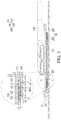
- FIG. 1 is a schematic exploded view of application of a heat dissipation structure to a heat generating element according to a first embodiment of the disclosure.
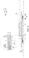
- FIG. 2 is a schematic three-dimensional upward view of a heat dissipation body and an elastomer in FIG. 1 .
- FIG. 3 is a schematic view of an enlarged local profile of FIG. 1 .
- a heat dissipation structure 100 of the disclosure includes a heat dissipation body 110 and an elastomer 120.
- the heat dissipation structure 100 is disposed on a heat generating element 200.
- the heat generating element 200 is disposed on a substrate 220, and the heat generating element 200 and the substrate 220 are combined and taken as a functional module 20.
- the functional module 20 is, for example, a central processing unit (CPU) is disposed on a main board 30.
- the functional module 20 is also a graphics processing unit (GPU) or other electronic elements, and is not limited herein.
- the heat dissipation body 110 includes a connecting portion 111, and the connecting portion 111 includes a central area 112 and a peripheral area 113.
- the peripheral area 113 surrounds the central area 112 and a thickness H1 of the central area 112 is greater than a thickness H2 of the peripheral area 113.
- the elastomer 120 is disposed annularly in the peripheral area 113 of the connecting portion 111 of the heat dissipation body 110, but in other embodiments, the elastomer is not limited thereto.
- a heat-conducting medium C is coated between the heat generating element 200 and the heat dissipation structure 100.
- the elastomer 120 is located between the connecting portion 111 and the heat generating element 200 and presses against the heat generating element 200, so that the connecting portion 111, the elastomer 120, and the heat generating element 200 form a sealed space S together.
- the heat-conducting medium C is, for example, liquid metal thermal grease, but in other embodiments, the heat-conducting medium is not limited thereto.
- the elastomer 120 is, for example, foam (such as high-density foam), but in other embodiments, the elastomer 120 is also rubber, silica gel, or other materials that are compressed and prevents the heat-conducting medium C from overflowing, and the elastomer is not limited to the above.
- the central area 112 of the connecting portion 111 squeezes the heat-conducting medium C coated on the heat generating element 200. At this time, a portion of the heat-conducting medium C overflows into the sealed space S. Therefore, a short circuit or a burned part caused by an overflow of the heat-conducting medium C to a circuit structure is avoid.
- the elastomer 120 is made of a compressible material. Therefore, when the elastomer 120 is located between the connecting portion 111 and the heat generating element 200 and presses against the heat generating element 200, the elastomer 120 is in close contact with the connecting portion 111 and the heat generating element 200, so that the sealed space S formed by the connecting portion 111, the elastomer 120, and the heat generating element 200 prevents the heat-conducting medium C from overflowing effectively.
- the central area 112 of the connecting portion 111 protrudes from the peripheral area 113.
- the heat generating element 200 includes a protrusion 210 facing the central area 112, and when the connecting portion 111 is disposed on the heat generating element 200, the central area 112 is corresponding to the protrusion 210.
- the connecting portion 111 includes the protruded central area 112 raises a distance between the peripheral area 113 of the connecting portion 111 and an edge of the heat generating element 200, and the distance is greater than or equal to 1 millimeter (for example, 1 millimeter to 1.5 millimeters). The disclosure is not limited thereto.
- a thickness T of the elastomer 120 is 1 millimeter, but in other embodiments, the thickness T of the elastomer 120 is between 0.5 millimeter and 1.5 millimeters.
- the elastomer 120 includes a first side wall 121 facing the central area 112, and the central area 112 includes a second side wall 1121 opposite to the first side wall 121.
- a distance D between the first side wall 121 of the elastomer 120 and the second side wall 1121 of the central area 112 is between 1 millimeter and 3 millimeters, so that the sealed space S formed by the connecting portion 111, the elastomer 120, and the heat generating element 200 is sufficient to accommodate the heat-conducting medium C.
- the heat dissipation body 110 further includes a heat pipe 130.
- a heat pipe 130 In FIG. 1 to FIG. 3 , only a part of the heat pipe 130 is depicted. Heat energy of the heat dissipation body 110 is thermally coupled to a fin or other places via the heat pipe 130.
- the heat dissipation body 110 does not include the heat pipe 130, and a form of the heat dissipation body 110 is not limited thereto.
- FIG. 4 to FIG. 6 are schematic views of enlarged local profiles of application of a heat dissipation structure to a heat generating element according to a plurality of embodiments of the disclosure.
- the heat generating element 200 is disposed on the substrate 220.
- An elastomer 120A of a heat dissipation structure 100A in this embodiment is slightly different from the elastomer 120 of the heat dissipation structure 100 in FIG. 3 .
- the elastomer 120 in FIG. 3 includes the first portion 122 contacting with the heat generating element 200 and the second portion 123 extending beyond the edge E of the heat generating element 200.
- the second portion 123 is suspended over the substrate 220.
- a second portion 123A of the elastomer 120A extends along an outer surface W of the heat generating element 200 to the substrate 220. That is, the second portion 123A is closely attached to the outer surface W and the substrate 220.
- an elastomer 120B of a heat dissipation structure 100B in this embodiment is slightly different from the elastomer 120 of the heat dissipation structure 100 in FIG. 3 .
- the elastomer 120B in FIG. 3 does not include the second portion 123 extending beyond the edge E of the heat generating element 200 in FIG. 3 .
- the elastomer 120B is aligned with the edge E of the heat generating element 200, but in other embodiments, the elastomer 120B extends to the edge E of the heat generating element 200.
- a heat dissipation body 110C of a heat dissipation structure 100C in this embodiment is slightly different from the heat dissipation body 110 of the heat dissipation structure 100 in FIG. 3 .
- a central area 112A and a peripheral area 113A of a connecting portion 111C are equal in height, and a thickness of an elastomer 120C is less than that of the elastomer 120.
- the disclosure is not limited thereto, and the central area 112A of the connecting portion 111C does not protrude from the peripheral area 113A.
- the central area 112A is actually flush with the peripheral area 113A.
- the central area 112A and the peripheral area 113A are planar, but in other embodiments, the central area 112A and the peripheral area 113A may also be non-planar, which is not limited herein.
- the heat dissipation body includes a central area and a peripheral area located on the connecting portion.
- the elastomer is disposed annularly in the peripheral area of the connecting portion of the heat dissipation body.
- the elastomer is located between the heat dissipation body and the heat generating element and presses against the heat generating element, so that the heat dissipation body, the elastomer, and the heat generating element form a sealed space together.
- the heat-conducting medium coated on the heat generating element is squeezed by the central area of the heat dissipation body, so that a portion of the heat-conducting medium is suitable to overflow into the sealed space.
- the sealed space of the heat dissipation structure of the disclosure accommodates the heat-conducting medium, so that the heat-conducting medium does not overflow outside, thereby cause a short circuit or a burned part.
Landscapes
- Engineering & Computer Science (AREA)
- Microelectronics & Electronic Packaging (AREA)
- Physics & Mathematics (AREA)
- Thermal Sciences (AREA)
- Theoretical Computer Science (AREA)
- Human Computer Interaction (AREA)
- General Engineering & Computer Science (AREA)
- General Physics & Mathematics (AREA)
- Cooling Or The Like Of Semiconductors Or Solid State Devices (AREA)
- Cooling Or The Like Of Electrical Apparatus (AREA)
Abstract
Description
- This application claims the priority benefit of Taiwan Application Serial No.
108202567, filed on March 4, 2019 - The disclosure relates to a heat dissipation structure.
- In recent years, with the development of science and technology, electronic products such as a desktop computer, a notebook computer, and a tablet computer have been widely used in daily life. An electronic device is equipped with a central processing unit (CPU), a graphics processing unit (GPU), or other electronic elements that generate heat during operation. A common heat dissipation manner is to apply thermal dissipation grease between a heat dissipation component and a heat generating element. The thermal grease fills up a gap between the heat dissipation component and the heat generating element, and conduct heat generated from the heat generating element to the heat dissipation component, to achieve heat dissipation.
- As for existing liquid metal thermal grease, conventional thermal grease is doped with a metal material having a high thermal conductivity to further enhance a thermal conductivity of the conventional thermal grease. However, because of the properties of conductivity and fluidity, the liquid metal thermal grease may overflow during movement of an electronic product, resulting in the following disadvantage such as a short circuit or a burned part while using.
- The disclosure provides a heat dissipation structure applied to a substrate with a heat generating element. The heat dissipation structure includes a heat dissipation body and an elastomer. The heat dissipation body includes a connecting portion, where the connecting portion includes a central area and a peripheral area, and the central area is configured to contact with the heat generating element. The elastomer is disposed between the peripheral area and the heat generating element to form a sealed space, and the sealed space is configured to accommodate a heat-conducting medium.
- In the heat dissipation structure of the disclosure, when the heat dissipation structure is disposed on the heat generating element, the elastomer is located between the heat dissipation body and the heat generating element and presses against the heat generating element, so that the heat dissipation body, the elastomer, and the heat generating element form the sealed space together. At this time, the heat-conducting medium coated on the heat generating element is squeezed by the central area of the heat dissipation body, so that a portion of the heat-conducting medium is suitable to overflow into the sealed space. In other words, the sealed space of the heat dissipation structure of the disclosure accommodates redundant heat-conducting medium, so that the heat-conducting medium does not overflow outside and does not cause a short circuit or a burned part.
-
-
FIG. 1 is a schematic exploded view of application of a heat dissipation structure to a heat generating element according to a first embodiment of the disclosure. -
FIG. 2 is a schematic three-dimensional upward view of a heat dissipation body and an elastomer inFIG. 1 . -
FIG. 3 is a schematic view of an enlarged local profile ofFIG. 1 . -
FIG. 4 to FIG. 6 are schematic views of enlarged local profiles of application of a heat dissipation structure to a heat generating element according to a plurality of embodiments of the disclosure. -
FIG. 1 is a schematic exploded view of application of a heat dissipation structure to a heat generating element according to a first embodiment of the disclosure.FIG. 2 is a schematic three-dimensional upward view of a heat dissipation body and an elastomer inFIG. 1 .FIG. 3 is a schematic view of an enlarged local profile ofFIG. 1 . Referring toFIG. 1 ,FIG. 2 , andFIG. 3 , aheat dissipation structure 100 of the disclosure includes aheat dissipation body 110 and anelastomer 120. Theheat dissipation structure 100 is disposed on a heat generatingelement 200. - In this embodiment, the heat generating
element 200 is disposed on asubstrate 220, and the heat generatingelement 200 and thesubstrate 220 are combined and taken as afunctional module 20. In this embodiment, thefunctional module 20 is, for example, a central processing unit (CPU) is disposed on amain board 30. However, in other embodiments, thefunctional module 20 is also a graphics processing unit (GPU) or other electronic elements, and is not limited herein. - Referring to
FIG. 2 , theheat dissipation body 110 includes a connectingportion 111, and the connectingportion 111 includes acentral area 112 and aperipheral area 113. Theperipheral area 113 surrounds thecentral area 112 and a thickness H1 of thecentral area 112 is greater than a thickness H2 of theperipheral area 113. In this embodiment, theelastomer 120 is disposed annularly in theperipheral area 113 of the connectingportion 111 of theheat dissipation body 110, but in other embodiments, the elastomer is not limited thereto. - Referring to
FIG. 3 , a heat-conducting medium C is coated between the heat generatingelement 200 and theheat dissipation structure 100. When theheat dissipation structure 100 is disposed on the heat generatingelement 200, theelastomer 120 is located between the connectingportion 111 and the heat generatingelement 200 and presses against the heat generatingelement 200, so that the connectingportion 111, theelastomer 120, and the heat generatingelement 200 form a sealed space S together. - In this embodiment, the heat-conducting medium C is, for example, liquid metal thermal grease, but in other embodiments, the heat-conducting medium is not limited thereto. In this embodiment, the
elastomer 120 is, for example, foam (such as high-density foam), but in other embodiments, theelastomer 120 is also rubber, silica gel, or other materials that are compressed and prevents the heat-conducting medium C from overflowing, and the elastomer is not limited to the above. - As such, when the
heat dissipation structure 100 is disposed on the heat generatingelement 200, thecentral area 112 of the connectingportion 111 squeezes the heat-conducting medium C coated on the heat generatingelement 200. At this time, a portion of the heat-conducting medium C overflows into the sealed space S. Therefore, a short circuit or a burned part caused by an overflow of the heat-conducting medium C to a circuit structure is avoid. - In an embodiment, the
elastomer 120 is made of a compressible material. Therefore, when theelastomer 120 is located between the connectingportion 111 and the heat generatingelement 200 and presses against the heat generatingelement 200, theelastomer 120 is in close contact with the connectingportion 111 and the heat generatingelement 200, so that the sealed space S formed by the connectingportion 111, theelastomer 120, and the heat generatingelement 200 prevents the heat-conducting medium C from overflowing effectively. - In an embodiment, the
central area 112 of the connectingportion 111 protrudes from theperipheral area 113. The heat generatingelement 200 includes aprotrusion 210 facing thecentral area 112, and when the connectingportion 111 is disposed on the heat generatingelement 200, thecentral area 112 is corresponding to theprotrusion 210. In this embodiment, the connectingportion 111 includes the protrudedcentral area 112 raises a distance between theperipheral area 113 of the connectingportion 111 and an edge of the heat generatingelement 200, and the distance is greater than or equal to 1 millimeter (for example, 1 millimeter to 1.5 millimeters). The disclosure is not limited thereto. - In an embodiment, a thickness T of the
elastomer 120 is 1 millimeter, but in other embodiments, the thickness T of theelastomer 120 is between 0.5 millimeter and 1.5 millimeters. Theelastomer 120 includes afirst side wall 121 facing thecentral area 112, and thecentral area 112 includes asecond side wall 1121 opposite to thefirst side wall 121. A distance D between thefirst side wall 121 of theelastomer 120 and thesecond side wall 1121 of thecentral area 112 is between 1 millimeter and 3 millimeters, so that the sealed space S formed by the connectingportion 111, theelastomer 120, and the heat generatingelement 200 is sufficient to accommodate the heat-conducting medium C. - In this embodiment, the
heat dissipation body 110 further includes aheat pipe 130. InFIG. 1 to FIG. 3 , only a part of theheat pipe 130 is depicted. Heat energy of theheat dissipation body 110 is thermally coupled to a fin or other places via theheat pipe 130. Definitely, in other embodiments, theheat dissipation body 110 does not include theheat pipe 130, and a form of theheat dissipation body 110 is not limited thereto. - Other embodiments are listed below for description. It needs to be noted herein that in the following embodiments, reference numerals and a portion of the foregoing embodiments are used, and same reference numerals are used to represent same or similar elements, and descriptions about same technical contents are omitted. For the omitted descriptions, reference is made to the foregoing embodiments, and details are not repeated again in the following embodiments.
-
FIG. 4 to FIG. 6 are schematic views of enlarged local profiles of application of a heat dissipation structure to a heat generating element according to a plurality of embodiments of the disclosure. Referring first toFIG. 4 , the heat generatingelement 200 is disposed on thesubstrate 220. Anelastomer 120A of aheat dissipation structure 100A in this embodiment is slightly different from theelastomer 120 of theheat dissipation structure 100 inFIG. 3 . Theelastomer 120 inFIG. 3 includes thefirst portion 122 contacting with the heat generatingelement 200 and thesecond portion 123 extending beyond the edge E of theheat generating element 200. - The
second portion 123 is suspended over thesubstrate 220. In this embodiment, asecond portion 123A of theelastomer 120A extends along an outer surface W of the heat generatingelement 200 to thesubstrate 220. That is, thesecond portion 123A is closely attached to the outer surface W and thesubstrate 220. An advantage of this method is that a sealing area and a sealing effect are further enhanced, thereby preventing the heat-conducting medium C from overflowing from the sealed space S more effectively. - Next, referring to
FIG. 5 , anelastomer 120B of aheat dissipation structure 100B in this embodiment is slightly different from theelastomer 120 of theheat dissipation structure 100 inFIG. 3 . Theelastomer 120B inFIG. 3 does not include thesecond portion 123 extending beyond the edge E of theheat generating element 200 inFIG. 3 . In this embodiment, theelastomer 120B is aligned with the edge E of theheat generating element 200, but in other embodiments, theelastomer 120B extends to the edge E of theheat generating element 200. - Referring to
FIG. 6 , aheat dissipation body 110C of aheat dissipation structure 100C in this embodiment is slightly different from theheat dissipation body 110 of theheat dissipation structure 100 inFIG. 3 . In this embodiment inFIG. 3 , acentral area 112A and aperipheral area 113A of a connectingportion 111C are equal in height, and a thickness of anelastomer 120C is less than that of theelastomer 120. However, the disclosure is not limited thereto, and thecentral area 112A of the connectingportion 111C does not protrude from theperipheral area 113A. Thecentral area 112A is actually flush with theperipheral area 113A. Definitely, in this embodiment, thecentral area 112A and theperipheral area 113A are planar, but in other embodiments, thecentral area 112A and theperipheral area 113A may also be non-planar, which is not limited herein. - In summary, in the heat dissipation structure of the disclosure, the heat dissipation body includes a central area and a peripheral area located on the connecting portion. The elastomer is disposed annularly in the peripheral area of the connecting portion of the heat dissipation body. When the heat dissipation structure is disposed on the heat generating element, the elastomer is located between the heat dissipation body and the heat generating element and presses against the heat generating element, so that the heat dissipation body, the elastomer, and the heat generating element form a sealed space together. At this time, the heat-conducting medium coated on the heat generating element is squeezed by the central area of the heat dissipation body, so that a portion of the heat-conducting medium is suitable to overflow into the sealed space. In other words, the sealed space of the heat dissipation structure of the disclosure accommodates the heat-conducting medium, so that the heat-conducting medium does not overflow outside, thereby cause a short circuit or a burned part.
- Although the disclosure is described with reference to the above embodiments, the embodiments are not intended to limit the disclosure. A person of ordinary skill in the art may make variations and modifications without departing from the spirit and scope of the disclosure. Therefore, the protection scope of the disclosure should be subject to the appended claims.
Claims (8)
- A heat dissipation structure, applied to a substrate with a heat generating element, comprising:a heat dissipation body, having a connecting portion, wherein the connecting portion comprises a central area and a peripheral area, and the central area is configured to contact with the heat generating element;an elastomer, disposed between the peripheral area and the heat generating element, to form a sealed space, wherein the sealed space is configured to accommodate a heat-conducting medium.
- The heat dissipation structure according to claim 1, wherein the heat generating element comprises a protrusion, and the central area is corresponding to the protrusion.
- The heat dissipation structure according to claim 1, wherein a thickness of the central area is greater than a thickness of the peripheral area.
- The heat dissipation structure according to claim 1, wherein a thickness of the central area is equal to a thickness of the peripheral area.
- The heat dissipation structure according to claim 1, wherein the elastomer comprises a first portion contacting with the heat generating element and a second portion extending beyond an edge of the heat generating element.
- The heat dissipation structure according to claim 5, wherein the second portion extends along an outer surface of the heat generating element to the substrate.
- The heat dissipation structure according to claim 1, wherein the heat dissipation body further comprises a heat pipe.
- The heat dissipation structure according to claim 1, wherein the elastomer comprises foam, rubber, silica gel or the combination of thereof.
Applications Claiming Priority (1)
| Application Number | Priority Date | Filing Date | Title |
|---|---|---|---|
| TW108202567U TWM579819U (en) | 2019-03-04 | 2019-03-04 | Heat dissipation structure |
Publications (2)
| Publication Number | Publication Date |
|---|---|
| EP3705978A1 true EP3705978A1 (en) | 2020-09-09 |
| EP3705978B1 EP3705978B1 (en) | 2023-04-05 |
Family
ID=67703454
Family Applications (1)
| Application Number | Title | Priority Date | Filing Date |
|---|---|---|---|
| EP20160941.9A Active EP3705978B1 (en) | 2019-03-04 | 2020-03-04 | Heat dissipation structure |
Country Status (4)
| Country | Link |
|---|---|
| US (1) | US11172594B2 (en) |
| EP (1) | EP3705978B1 (en) |
| PL (1) | PL3705978T3 (en) |
| TW (1) | TWM579819U (en) |
Cited By (1)
| Publication number | Priority date | Publication date | Assignee | Title |
|---|---|---|---|---|
| EP4113247A1 (en) * | 2021-06-30 | 2023-01-04 | Micro-Star Int'l Co., Limited | Heat dissipation structure assembly |
Families Citing this family (4)
| Publication number | Priority date | Publication date | Assignee | Title |
|---|---|---|---|---|
| JP7273116B2 (en) * | 2021-08-27 | 2023-05-12 | レノボ・シンガポール・プライベート・リミテッド | Electronics and cooling modules |
| CN114501961A (en) * | 2022-03-21 | 2022-05-13 | 联想(北京)有限公司 | Electronic device and method for manufacturing the same |
| WO2024073430A1 (en) * | 2022-09-28 | 2024-04-04 | Cisco Technology, Inc. | Heatsink for ring type integrated circuits |
| TWI850991B (en) * | 2023-01-30 | 2024-08-01 | 宏碁股份有限公司 | Electronic package module |
Citations (3)
| Publication number | Priority date | Publication date | Assignee | Title |
|---|---|---|---|---|
| US5561590A (en) * | 1995-09-21 | 1996-10-01 | Unisys Corporation | Heat transfer sub-assembly incorporating liquid metal surrounded by a seal ring |
| US20070045819A1 (en) * | 2005-07-19 | 2007-03-01 | International Business Machines Corporation | Thermal paste containment for semiconductor modules |
| US20160021781A1 (en) * | 2014-07-18 | 2016-01-21 | Thales | Thermal interface device with microporous seal capable of preventing the migration of thermal grease |
Family Cites Families (14)
| Publication number | Priority date | Publication date | Assignee | Title |
|---|---|---|---|---|
| US6016006A (en) * | 1996-06-24 | 2000-01-18 | Intel Corporation | Thermal grease insertion and retention |
| KR100446290B1 (en) * | 2001-11-03 | 2004-09-01 | 삼성전자주식회사 | Semiconductor package having dam and fabricating method the same |
| US7218000B2 (en) * | 2003-06-27 | 2007-05-15 | Intel Corporation | Liquid solder thermal interface material contained within a cold-formed barrier and methods of making same |
| US7063127B2 (en) * | 2003-09-18 | 2006-06-20 | International Business Machines Corporation | Method and apparatus for chip-cooling |
| US7215551B2 (en) * | 2004-09-29 | 2007-05-08 | Super Talent Electronics, Inc. | Memory module assembly including heat sink attached to integrated circuits by adhesive |
| US7961469B2 (en) * | 2009-03-31 | 2011-06-14 | Apple Inc. | Method and apparatus for distributing a thermal interface material |
| CA2676495C (en) * | 2009-08-24 | 2014-04-08 | Ibm Canada Limited - Ibm Canada Limitee | Mechanical barrier element for improved thermal reliability of electronic components |
| US9210832B2 (en) * | 2012-08-13 | 2015-12-08 | Asustek Computer Inc. | Thermal buffering element |
| US8934250B2 (en) | 2012-09-26 | 2015-01-13 | International Business Machines Corporation | Immersion-cooling of selected electronic component(s) mounted to printed circuit board |
| US10399190B2 (en) * | 2014-08-08 | 2019-09-03 | Dell Products, L.P. | Liquid-vapor phase change thermal interface material |
| JP6320332B2 (en) * | 2015-03-10 | 2018-05-09 | 東芝メモリ株式会社 | Electronics |
| US10049896B2 (en) * | 2015-12-09 | 2018-08-14 | International Business Machines Corporation | Lid attach optimization to limit electronic package warpage |
| CN106455427B (en) | 2016-09-29 | 2019-03-05 | 努比亚技术有限公司 | A kind of mobile terminal |
| CN106413371A (en) | 2016-11-30 | 2017-02-15 | 依偎科技(南昌)有限公司 | Mobile terminal and preparation method thereof |
-
2019
- 2019-03-04 TW TW108202567U patent/TWM579819U/en unknown
-
2020
- 2020-02-18 US US16/792,947 patent/US11172594B2/en active Active
- 2020-03-04 EP EP20160941.9A patent/EP3705978B1/en active Active
- 2020-03-04 PL PL20160941.9T patent/PL3705978T3/en unknown
Patent Citations (3)
| Publication number | Priority date | Publication date | Assignee | Title |
|---|---|---|---|---|
| US5561590A (en) * | 1995-09-21 | 1996-10-01 | Unisys Corporation | Heat transfer sub-assembly incorporating liquid metal surrounded by a seal ring |
| US20070045819A1 (en) * | 2005-07-19 | 2007-03-01 | International Business Machines Corporation | Thermal paste containment for semiconductor modules |
| US20160021781A1 (en) * | 2014-07-18 | 2016-01-21 | Thales | Thermal interface device with microporous seal capable of preventing the migration of thermal grease |
Cited By (1)
| Publication number | Priority date | Publication date | Assignee | Title |
|---|---|---|---|---|
| EP4113247A1 (en) * | 2021-06-30 | 2023-01-04 | Micro-Star Int'l Co., Limited | Heat dissipation structure assembly |
Also Published As
| Publication number | Publication date |
|---|---|
| TWM579819U (en) | 2019-06-21 |
| US11172594B2 (en) | 2021-11-09 |
| PL3705978T3 (en) | 2023-08-07 |
| US20200288604A1 (en) | 2020-09-10 |
| EP3705978B1 (en) | 2023-04-05 |
Similar Documents
| Publication | Publication Date | Title |
|---|---|---|
| US11172594B2 (en) | Heat dissipation structure | |
| JP4144983B2 (en) | Thin electromagnetic interference shield with heat spreading plate | |
| US20140311713A1 (en) | Heat dissipation component | |
| US20190045666A1 (en) | Electronic device heat transfer system and related methods | |
| US20170188448A1 (en) | Electronic device heat transfer system and related methods | |
| US10796978B2 (en) | TIM strain mitigation in electronic modules | |
| JP2019032134A (en) | Plate type heat transport device and electronic apparatus | |
| US7081669B2 (en) | Device and system for heat spreader with controlled thermal expansion | |
| JP2011035397A (en) | Sealing for pattern-formed metal thermal interface | |
| US11792912B2 (en) | Heat dissipation structure with stacked thermal interface materials | |
| US12002733B2 (en) | Heat dissipation structure, manufacturing method for heat dissipation structure, and electronic apparatus | |
| US8649178B2 (en) | Heat dissipation module for electronic apparatus | |
| JP2020088273A (en) | Electronics | |
| US20240243114A1 (en) | Electronic package structure | |
| WO2018184595A1 (en) | Heat dissipation devices | |
| CN116367489A (en) | The structure of the uniform temperature cooling device | |
| CN209543257U (en) | Heat radiation structure | |
| US20060238981A1 (en) | Heat-dissipation device with elastic member and heat-dissipation method thereof | |
| US9335801B2 (en) | Frame and electronic device having the same | |
| CN217445693U (en) | Heat radiation structure | |
| CN209964509U (en) | heat dissipation structure | |
| US20050133907A1 (en) | Mechanism for maintaining consistent thermal interface layer in an integrated circuit assembly | |
| US20080106868A1 (en) | Thermal interface material volume between thermal conducting members | |
| CN115551174A (en) | Heat dissipation structure assembly | |
| JP7554303B1 (en) | Heat dissipation structure and portable information device |
Legal Events
| Date | Code | Title | Description |
|---|---|---|---|
| PUAI | Public reference made under article 153(3) epc to a published international application that has entered the european phase |
Free format text: ORIGINAL CODE: 0009012 |
|
| STAA | Information on the status of an ep patent application or granted ep patent |
Free format text: STATUS: THE APPLICATION HAS BEEN PUBLISHED |
|
| AK | Designated contracting states |
Kind code of ref document: A1 Designated state(s): AL AT BE BG CH CY CZ DE DK EE ES FI FR GB GR HR HU IE IS IT LI LT LU LV MC MK MT NL NO PL PT RO RS SE SI SK SM TR |
|
| AX | Request for extension of the european patent |
Extension state: BA ME |
|
| STAA | Information on the status of an ep patent application or granted ep patent |
Free format text: STATUS: REQUEST FOR EXAMINATION WAS MADE |
|
| 17P | Request for examination filed |
Effective date: 20201130 |
|
| RBV | Designated contracting states (corrected) |
Designated state(s): AL AT BE BG CH CY CZ DE DK EE ES FI FR GB GR HR HU IE IS IT LI LT LU LV MC MK MT NL NO PL PT RO RS SE SI SK SM TR |
|
| STAA | Information on the status of an ep patent application or granted ep patent |
Free format text: STATUS: EXAMINATION IS IN PROGRESS |
|
| 17Q | First examination report despatched |
Effective date: 20211112 |
|
| RIC1 | Information provided on ipc code assigned before grant |
Ipc: H01L 23/427 20060101ALI20221028BHEP Ipc: H01L 23/42 20060101ALI20221028BHEP Ipc: H01L 23/40 20060101ALI20221028BHEP Ipc: H01L 23/367 20060101ALI20221028BHEP Ipc: H05K 7/20 20060101ALI20221028BHEP Ipc: G06F 1/20 20060101AFI20221028BHEP |
|
| INTG | Intention to grant announced |
Effective date: 20221125 |
|
| INTG | Intention to grant announced |
Effective date: 20221130 |
|
| GRAS | Grant fee paid |
Free format text: ORIGINAL CODE: EPIDOSNIGR3 |
|
| STAA | Information on the status of an ep patent application or granted ep patent |
Free format text: STATUS: GRANT OF PATENT IS INTENDED |
|
| GRAA | (expected) grant |
Free format text: ORIGINAL CODE: 0009210 |
|
| STAA | Information on the status of an ep patent application or granted ep patent |
Free format text: STATUS: THE PATENT HAS BEEN GRANTED |
|
| AK | Designated contracting states |
Kind code of ref document: B1 Designated state(s): AL AT BE BG CH CY CZ DE DK EE ES FI FR GB GR HR HU IE IS IT LI LT LU LV MC MK MT NL NO PL PT RO RS SE SI SK SM TR |
|
| REG | Reference to a national code |
Ref country code: GB Ref legal event code: FG4D |
|
| REG | Reference to a national code |
Ref country code: DE Ref legal event code: R096 Ref document number: 602020009357 Country of ref document: DE |
|
| REG | Reference to a national code |
Ref country code: CH Ref legal event code: EP |
|
| REG | Reference to a national code |
Ref country code: AT Ref legal event code: REF Ref document number: 1558721 Country of ref document: AT Kind code of ref document: T Effective date: 20230415 |
|
| REG | Reference to a national code |
Ref country code: IE Ref legal event code: FG4D |
|
| P01 | Opt-out of the competence of the unified patent court (upc) registered |
Effective date: 20230530 |
|
| REG | Reference to a national code |
Ref country code: LT Ref legal event code: MG9D |
|
| REG | Reference to a national code |
Ref country code: NL Ref legal event code: MP Effective date: 20230405 |
|
| REG | Reference to a national code |
Ref country code: AT Ref legal event code: MK05 Ref document number: 1558721 Country of ref document: AT Kind code of ref document: T Effective date: 20230405 |
|
| PG25 | Lapsed in a contracting state [announced via postgrant information from national office to epo] |
Ref country code: NL Free format text: LAPSE BECAUSE OF FAILURE TO SUBMIT A TRANSLATION OF THE DESCRIPTION OR TO PAY THE FEE WITHIN THE PRESCRIBED TIME-LIMIT Effective date: 20230405 |
|
| PG25 | Lapsed in a contracting state [announced via postgrant information from national office to epo] |
Ref country code: SE Free format text: LAPSE BECAUSE OF FAILURE TO SUBMIT A TRANSLATION OF THE DESCRIPTION OR TO PAY THE FEE WITHIN THE PRESCRIBED TIME-LIMIT Effective date: 20230405 Ref country code: PT Free format text: LAPSE BECAUSE OF FAILURE TO SUBMIT A TRANSLATION OF THE DESCRIPTION OR TO PAY THE FEE WITHIN THE PRESCRIBED TIME-LIMIT Effective date: 20230807 Ref country code: NO Free format text: LAPSE BECAUSE OF FAILURE TO SUBMIT A TRANSLATION OF THE DESCRIPTION OR TO PAY THE FEE WITHIN THE PRESCRIBED TIME-LIMIT Effective date: 20230705 Ref country code: ES Free format text: LAPSE BECAUSE OF FAILURE TO SUBMIT A TRANSLATION OF THE DESCRIPTION OR TO PAY THE FEE WITHIN THE PRESCRIBED TIME-LIMIT Effective date: 20230405 Ref country code: AT Free format text: LAPSE BECAUSE OF FAILURE TO SUBMIT A TRANSLATION OF THE DESCRIPTION OR TO PAY THE FEE WITHIN THE PRESCRIBED TIME-LIMIT Effective date: 20230405 |
|
| PG25 | Lapsed in a contracting state [announced via postgrant information from national office to epo] |
Ref country code: RS Free format text: LAPSE BECAUSE OF FAILURE TO SUBMIT A TRANSLATION OF THE DESCRIPTION OR TO PAY THE FEE WITHIN THE PRESCRIBED TIME-LIMIT Effective date: 20230405 Ref country code: LV Free format text: LAPSE BECAUSE OF FAILURE TO SUBMIT A TRANSLATION OF THE DESCRIPTION OR TO PAY THE FEE WITHIN THE PRESCRIBED TIME-LIMIT Effective date: 20230405 Ref country code: LT Free format text: LAPSE BECAUSE OF FAILURE TO SUBMIT A TRANSLATION OF THE DESCRIPTION OR TO PAY THE FEE WITHIN THE PRESCRIBED TIME-LIMIT Effective date: 20230405 Ref country code: IS Free format text: LAPSE BECAUSE OF FAILURE TO SUBMIT A TRANSLATION OF THE DESCRIPTION OR TO PAY THE FEE WITHIN THE PRESCRIBED TIME-LIMIT Effective date: 20230805 Ref country code: HR Free format text: LAPSE BECAUSE OF FAILURE TO SUBMIT A TRANSLATION OF THE DESCRIPTION OR TO PAY THE FEE WITHIN THE PRESCRIBED TIME-LIMIT Effective date: 20230405 Ref country code: GR Free format text: LAPSE BECAUSE OF FAILURE TO SUBMIT A TRANSLATION OF THE DESCRIPTION OR TO PAY THE FEE WITHIN THE PRESCRIBED TIME-LIMIT Effective date: 20230706 Ref country code: AL Free format text: LAPSE BECAUSE OF FAILURE TO SUBMIT A TRANSLATION OF THE DESCRIPTION OR TO PAY THE FEE WITHIN THE PRESCRIBED TIME-LIMIT Effective date: 20230405 |
|
| PG25 | Lapsed in a contracting state [announced via postgrant information from national office to epo] |
Ref country code: FI Free format text: LAPSE BECAUSE OF FAILURE TO SUBMIT A TRANSLATION OF THE DESCRIPTION OR TO PAY THE FEE WITHIN THE PRESCRIBED TIME-LIMIT Effective date: 20230405 |
|
| REG | Reference to a national code |
Ref country code: DE Ref legal event code: R097 Ref document number: 602020009357 Country of ref document: DE |
|
| PG25 | Lapsed in a contracting state [announced via postgrant information from national office to epo] |
Ref country code: SK Free format text: LAPSE BECAUSE OF FAILURE TO SUBMIT A TRANSLATION OF THE DESCRIPTION OR TO PAY THE FEE WITHIN THE PRESCRIBED TIME-LIMIT Effective date: 20230405 |
|
| PG25 | Lapsed in a contracting state [announced via postgrant information from national office to epo] |
Ref country code: SM Free format text: LAPSE BECAUSE OF FAILURE TO SUBMIT A TRANSLATION OF THE DESCRIPTION OR TO PAY THE FEE WITHIN THE PRESCRIBED TIME-LIMIT Effective date: 20230405 Ref country code: SK Free format text: LAPSE BECAUSE OF FAILURE TO SUBMIT A TRANSLATION OF THE DESCRIPTION OR TO PAY THE FEE WITHIN THE PRESCRIBED TIME-LIMIT Effective date: 20230405 Ref country code: RO Free format text: LAPSE BECAUSE OF FAILURE TO SUBMIT A TRANSLATION OF THE DESCRIPTION OR TO PAY THE FEE WITHIN THE PRESCRIBED TIME-LIMIT Effective date: 20230405 Ref country code: EE Free format text: LAPSE BECAUSE OF FAILURE TO SUBMIT A TRANSLATION OF THE DESCRIPTION OR TO PAY THE FEE WITHIN THE PRESCRIBED TIME-LIMIT Effective date: 20230405 Ref country code: DK Free format text: LAPSE BECAUSE OF FAILURE TO SUBMIT A TRANSLATION OF THE DESCRIPTION OR TO PAY THE FEE WITHIN THE PRESCRIBED TIME-LIMIT Effective date: 20230405 Ref country code: CZ Free format text: LAPSE BECAUSE OF FAILURE TO SUBMIT A TRANSLATION OF THE DESCRIPTION OR TO PAY THE FEE WITHIN THE PRESCRIBED TIME-LIMIT Effective date: 20230405 |
|
| PLBE | No opposition filed within time limit |
Free format text: ORIGINAL CODE: 0009261 |
|
| STAA | Information on the status of an ep patent application or granted ep patent |
Free format text: STATUS: NO OPPOSITION FILED WITHIN TIME LIMIT |
|
| 26N | No opposition filed |
Effective date: 20240108 |
|
| PG25 | Lapsed in a contracting state [announced via postgrant information from national office to epo] |
Ref country code: SI Free format text: LAPSE BECAUSE OF FAILURE TO SUBMIT A TRANSLATION OF THE DESCRIPTION OR TO PAY THE FEE WITHIN THE PRESCRIBED TIME-LIMIT Effective date: 20230405 |
|
| PG25 | Lapsed in a contracting state [announced via postgrant information from national office to epo] |
Ref country code: SI Free format text: LAPSE BECAUSE OF FAILURE TO SUBMIT A TRANSLATION OF THE DESCRIPTION OR TO PAY THE FEE WITHIN THE PRESCRIBED TIME-LIMIT Effective date: 20230405 Ref country code: IT Free format text: LAPSE BECAUSE OF FAILURE TO SUBMIT A TRANSLATION OF THE DESCRIPTION OR TO PAY THE FEE WITHIN THE PRESCRIBED TIME-LIMIT Effective date: 20230405 |
|
| REG | Reference to a national code |
Ref country code: CH Ref legal event code: PL |
|
| PG25 | Lapsed in a contracting state [announced via postgrant information from national office to epo] |
Ref country code: BG Free format text: LAPSE BECAUSE OF FAILURE TO SUBMIT A TRANSLATION OF THE DESCRIPTION OR TO PAY THE FEE WITHIN THE PRESCRIBED TIME-LIMIT Effective date: 20230405 |
|
| PG25 | Lapsed in a contracting state [announced via postgrant information from national office to epo] |
Ref country code: LU Free format text: LAPSE BECAUSE OF NON-PAYMENT OF DUE FEES Effective date: 20240304 |
|
| PG25 | Lapsed in a contracting state [announced via postgrant information from national office to epo] |
Ref country code: MC Free format text: LAPSE BECAUSE OF FAILURE TO SUBMIT A TRANSLATION OF THE DESCRIPTION OR TO PAY THE FEE WITHIN THE PRESCRIBED TIME-LIMIT Effective date: 20230405 |
|
| GBPC | Gb: european patent ceased through non-payment of renewal fee |
Effective date: 20240304 |
|
| PG25 | Lapsed in a contracting state [announced via postgrant information from national office to epo] |
Ref country code: MC Free format text: LAPSE BECAUSE OF FAILURE TO SUBMIT A TRANSLATION OF THE DESCRIPTION OR TO PAY THE FEE WITHIN THE PRESCRIBED TIME-LIMIT Effective date: 20230405 Ref country code: BG Free format text: LAPSE BECAUSE OF FAILURE TO SUBMIT A TRANSLATION OF THE DESCRIPTION OR TO PAY THE FEE WITHIN THE PRESCRIBED TIME-LIMIT Effective date: 20230405 Ref country code: LU Free format text: LAPSE BECAUSE OF NON-PAYMENT OF DUE FEES Effective date: 20240304 |
|
| REG | Reference to a national code |
Ref country code: BE Ref legal event code: MM Effective date: 20240331 |
|
| PG25 | Lapsed in a contracting state [announced via postgrant information from national office to epo] |
Ref country code: BE Free format text: LAPSE BECAUSE OF NON-PAYMENT OF DUE FEES Effective date: 20240331 |
|
| PG25 | Lapsed in a contracting state [announced via postgrant information from national office to epo] |
Ref country code: GB Free format text: LAPSE BECAUSE OF NON-PAYMENT OF DUE FEES Effective date: 20240304 |
|
| PG25 | Lapsed in a contracting state [announced via postgrant information from national office to epo] |
Ref country code: IE Free format text: LAPSE BECAUSE OF NON-PAYMENT OF DUE FEES Effective date: 20240304 |
|
| PG25 | Lapsed in a contracting state [announced via postgrant information from national office to epo] |
Ref country code: IE Free format text: LAPSE BECAUSE OF NON-PAYMENT OF DUE FEES Effective date: 20240304 Ref country code: GB Free format text: LAPSE BECAUSE OF NON-PAYMENT OF DUE FEES Effective date: 20240304 Ref country code: BE Free format text: LAPSE BECAUSE OF NON-PAYMENT OF DUE FEES Effective date: 20240331 Ref country code: CH Free format text: LAPSE BECAUSE OF NON-PAYMENT OF DUE FEES Effective date: 20240331 |
|
| PG25 | Lapsed in a contracting state [announced via postgrant information from national office to epo] |
Ref country code: CY Free format text: LAPSE BECAUSE OF FAILURE TO SUBMIT A TRANSLATION OF THE DESCRIPTION OR TO PAY THE FEE WITHIN THE PRESCRIBED TIME-LIMIT; INVALID AB INITIO Effective date: 20200304 |
|
| PG25 | Lapsed in a contracting state [announced via postgrant information from national office to epo] |
Ref country code: HU Free format text: LAPSE BECAUSE OF FAILURE TO SUBMIT A TRANSLATION OF THE DESCRIPTION OR TO PAY THE FEE WITHIN THE PRESCRIBED TIME-LIMIT; INVALID AB INITIO Effective date: 20200304 |
|
| PG25 | Lapsed in a contracting state [announced via postgrant information from national office to epo] |
Ref country code: TR Free format text: LAPSE BECAUSE OF FAILURE TO SUBMIT A TRANSLATION OF THE DESCRIPTION OR TO PAY THE FEE WITHIN THE PRESCRIBED TIME-LIMIT Effective date: 20230405 |
|
| PGFP | Annual fee paid to national office [announced via postgrant information from national office to epo] |
Ref country code: FR Payment date: 20251120 Year of fee payment: 7 |
|
| PGFP | Annual fee paid to national office [announced via postgrant information from national office to epo] |
Ref country code: DE Payment date: 20251120 Year of fee payment: 7 |
|
| PGFP | Annual fee paid to national office [announced via postgrant information from national office to epo] |
Ref country code: PL Payment date: 20260107 Year of fee payment: 7 |