EP3705740B1 - Schraubverbindung und verfahren zur losdrehsicherung der schraubverbindung - Google Patents
Schraubverbindung und verfahren zur losdrehsicherung der schraubverbindung Download PDFInfo
- Publication number
- EP3705740B1 EP3705740B1 EP20160365.1A EP20160365A EP3705740B1 EP 3705740 B1 EP3705740 B1 EP 3705740B1 EP 20160365 A EP20160365 A EP 20160365A EP 3705740 B1 EP3705740 B1 EP 3705740B1
- Authority
- EP
- European Patent Office
- Prior art keywords
- front side
- rear side
- shaped body
- disc
- screw connection
- Prior art date
- Legal status (The legal status is an assumption and is not a legal conclusion. Google has not performed a legal analysis and makes no representation as to the accuracy of the status listed.)
- Active
Links
Images


Classifications
-
- F—MECHANICAL ENGINEERING; LIGHTING; HEATING; WEAPONS; BLASTING
- F16—ENGINEERING ELEMENTS AND UNITS; GENERAL MEASURES FOR PRODUCING AND MAINTAINING EFFECTIVE FUNCTIONING OF MACHINES OR INSTALLATIONS; THERMAL INSULATION IN GENERAL
- F16B—DEVICES FOR FASTENING OR SECURING CONSTRUCTIONAL ELEMENTS OR MACHINE PARTS TOGETHER, e.g. NAILS, BOLTS, CIRCLIPS, CLAMPS, CLIPS OR WEDGES; JOINTS OR JOINTING
- F16B39/00—Locking of screws, bolts or nuts
- F16B39/22—Locking of screws, bolts or nuts in which the locking takes place during screwing down or tightening
- F16B39/24—Locking of screws, bolts or nuts in which the locking takes place during screwing down or tightening by means of washers, spring washers, or resilient plates that lock against the object
Definitions
- the invention relates to a screw connection and a method for securing a screw connection against loosening.
- Lock washers can be used to prevent screw connections from loosening.
- the lock washers can have specially designed radial ribs, for example.
- the radial ribs can be located, for example, over the entire area on only one side of the locking washer or over the entire area on both sides of the locking washer.
- the radial ribs of the locking washer can be impressed into the respective counter-position due to the applied preload force.
- the resulting form fit can reliably prevent the screw connection from loosening itself, even under strong vibrations and dynamic loads, such as in a motor vehicle. Lock washers with radial ribs have been used essentially unchanged for a long time.
- the DE 44 29 312 A1 relates to a washer which is designed as a screw lock and is provided with tooth-like profiles on both sides.
- the DE 32 12 811 A1 relates to a threaded fastener washer having a cam formation, one face of the disc having an inner cam ring portion cooperating with said cam formation and the other face of the disc having a work-side, friction-enhancing working ring portion.
- the DE 20 2011 103330 U1 discloses a locking washer for screw connections with a receiving bore and an annular surface, the annular surface being provided with ribs on both sides.
- the invention is based on the object of creating an alternative and/or improved technique for securing a screw connection against loosening.
- the invention provides a device for securing a screw connection against loosening.
- the device has a disc-shaped body with a front side, a back side and a, preferably central, through hole that connects the front side with the back side.
- the front and the rear each have an inner annular surface that is flat (expediently in the unassembled state of the device), and an external annular surface that (expediently in the unassembled state of the device) is (for example partially or completely) profiled (/a profiled has surface), on.
- the device is used together with a screw with a profiled (e.g. ribbed) screw head underside or a nut with a profiled (e.g. ribbed) underside.
- a profiled (e.g. ribbed) screw head underside or a nut with a profiled (e.g. ribbed) underside When tightening the screw or the nut, the profiled underside of the screw head or the nut can emboss into the internal, planar annular surface of the front or the back of the disc-shaped body. Meanwhile the external, profiled annular surface of the disc-shaped body can impress itself in a contact surface of a component to be connected with the screw connection. There is a form fit between the component and the disk-shaped body and between the disk-shaped body and the screw or the nut. This results in a very effective anti-rotation device.
- the device can preferably be used on both sides in order to rule out incorrect assembly due to incorrect orientation of the disc-shaped body.
- the profiling of the outer annular surfaces is embossed, for example, in the disc-shaped body, e.g. B. in its production.
- the inner annular surface and the outer annular surface of the front and/or the rear adjoin each other. This can have the advantage that the internal, flat annular surface merges directly into the external, profiled annular surface.
- the disk-shaped body has an inner diameter which is adjacent to the inner annular surface of the front side and/or the rear side. It is possible for the disc-shaped body to have an outer diameter which is adjacent to the outer annular surface of the front side and/or the rear side.
- the inner annular surfaces and the outer annular surfaces can thus expediently completely form the front and the rear of the disc-shaped body.
- the inner annular surfaces of the front and rear are mirror-symmetrical to one another with respect to a center plane of the disc-shaped body. It is possible for the outer annular surfaces of the front and rear to be mirror-symmetrical to one another with respect to a center plane of the disc-shaped body.
- the front side and the back side can expediently be essentially mirror-symmetrical to one another in relation to a central plane of the disc-shaped body. Incorrect assembly of the disc-shaped body due to incorrect orientation can thus be ruled out.
- a surface area of the outer annular surface of the front and/or the rear is in a range between 25% and 200%, preferably in a range between 50% and 100%, particularly preferably in a range between 50% and 75%, an area of the inner annular surface of the front side and/or Back.
- An annular width of the inner annular surface of the front and/or rear can be smaller, equal to or greater than an annular width of the outer annular surface of the front and/or rear.
- the inner ring surface of the front and/or the back can be smaller, the same as or larger than the outer ring surface of the front and/or the back.
- the disc-shaped body is designed as a washer.
- the disc-shaped body can be used as a washer between a bolt head or nut and a holed member.
- the outer annular surface of the front and/or rear is designed to be pressed into a contact surface of a component to be connected by means of the screw connection. In this way, a positive connection can be produced between the disc-shaped body and the component for securing against loosening.
- the outer annular surface of the front and/or rear is raised (for example by less than 2 mm or by less than 1 mm) compared to the inner annular surface of the front and/or rear. It can thus be ensured that the external, profiled annular surface is impressed into the contact surface of the component to be connected with the screw connection before the internal, profiled annular surface comes into contact with the contact surface.
- the outer annular surface of the front and/or the back is ribbed.
- the outer annular surface of the front and/or the rear has a plurality of ribs, preferably radial ribs.
- a length of the ribs can preferably be greater than a width and/or a height of the ribs.
- a height of the ribs can preferably be constant along a length of the ribs.
- the ribs can expediently be embossed into the outer annular surface before the assembly of the disc-shaped body, preferably during production of the disc-shaped body.
- the outer annular surface of the front side and/or the rear side is toothed and/or has a plurality of spaced-apart projections, preferably nubs or teeth.
- the invention relates to a screw connection with a device for securing against loosening as disclosed herein.
- the screw connection also has a screw with a Screw head having a (e.g. partially or fully) profiled (e.g. ribbed or toothed) underside (e.g. already before assembly/tightening of the screw) which is designed to blend into the internal annular surface of the front or rear of the disk-shaped body.
- the profiled underside for example after assembly/tightening of the screw
- the screw connection can also have, for example, a nut with a (for example partially or completely) profiled (for example ribbed or toothed) underside (for example already profiled before assembly/tightening of the nut).
- the profiled underside can expediently be designed to emboss itself in the inner annular surface of the front side or the back side of the disc-shaped body.
- the profiled underside can be expediently embossed after the assembly/tightening of the nut in the inner annular surface of the front side or the back side of the disc-shaped body.
- the screw head or the nut can have an outer diameter that is equal to or smaller than an outer diameter of the inner annular surface of the front and/or the back of the disc-shaped body.
- the outer diameter of the screw head or the nut can be the same as or smaller than an inner diameter of the outer annular surface of the front and/or the rear of the disc-shaped body. This can prevent the profiled underside of the screw head or the nut from coming into contact with the external, profiled annular surface of the front side or the rear side of the disc-shaped body. This ensures that the profiled underside of the screw head or the nut can be stamped into the internal, planar annular surface of the front side or the back side of the disk-shaped body.
- the screw connection also has a component with a hole (e.g. blind hole, through hole, unthreaded hole, threaded hole, etc.) and a flat contact surface (e.g. before assembly/tightening of the screw or nut) that covers the hole surrounds, on.
- a hole e.g. blind hole, through hole, unthreaded hole, threaded hole, etc.
- a flat contact surface e.g. before assembly/tightening of the screw or nut
- the outer ring surface of the front side or the back side of the disc-shaped body is designed to emboss into the planar contact surface.
- the outer annular surface of the front or the back e.g. after assembly / tightening of the screw or nut
- a hardness of the outer annular surfaces can expediently be greater than a hardness of the flat contact surface, preferably with a hardness difference of greater than or equal to 40 HV.
- the invention also relates to a method for securing a screw connection against loosening by means of a device as disclosed herein.
- the method comprises using the disk-shaped body as a washer for a screw with a screw head having a (e.g. partially or fully) profiled (e.g. ribbed or serrated) underside, or for a nut having (e.g. partially or full) profiled (e.g. ribbed or serrated) underside (washer contact side).
- the underside can expediently be profiled before the screw or nut is tightened.
- the method further includes tightening the bolt or nut.
- the profiled underside of the screw or nut embosses into the inner ring section of one of the front and rear of the disc-shaped body, preferably to produce a form fit between the screw or nut and the disc-shaped body.
- the ring section on the outside of the other front and back of the disc-shaped body is impressed into a flat contact surface of a component, preferably to produce a form fit between the disc-shaped body and the component.
- the disk-shaped body can be used on both sides, with either the front or the rear in contact with the component.
- incorrect assembly can be prevented expediently.
- the device, thread connection and/or method as disclosed herein for any thread connection where anti-loosening is required or desired.
- the device, the screw connection and/or the method can be used in a motor vehicle, preferably a commercial vehicle (for example a truck or bus).
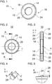
- the Figures 1 to 3 show different views of a device 10 for securing a screw connection or a screw connection against loosening.
- the device 10 can be used with any screw connection for connecting multiple components.
- the device 10 can be used to prevent a screw connection from loosening in a motor vehicle, preferably a commercial vehicle (for example a truck or bus).
- the device 10 has a preferably circular, disc-shaped body 12 .
- the disk-shaped body 12 has a front side 14 and a back side 16 .
- the front 14 and back 16 are directed in opposite directions.
- the disk-shaped body 12 has a through hole 18 .
- the through hole 18 connects the front 14 to the back 16.
- the through hole 18 in the middle disc-shaped body 12 may be arranged.
- the through hole 18 can be designed for the passage of a screw shank or a threaded rod through the disk-shaped body 12 .
- the device 10 is designed as a washer for a screw or nut.
- the front side 14 and the back side 16 each have a (radially) inner annular surface 20, 22 and a (radially) outer annular surface 24, 26.
- the inner ring surfaces 20, 22 have a substantially flat surface, that is, they are flat.
- the outer annular surfaces 24, 26 have a profiled surface, that is, they are profiled. The profiling can be over the entire surface with respect to the outer annular surfaces 24, 26, as shown. It is also possible that the outer annular surfaces 24, 26 are only partially profiled.
- the inner annular surfaces 20, 22 can delimit the through hole 18.
- an inner diameter of the disc-shaped body 12 borders on the inner annular surfaces 20, 22.
- An outer diameter of the disc-shaped body 12 can border on the outer annular surfaces 24, 26.
- On the front side 14 the inner annular surface 20 can adjoin the outer annular surface 24 .
- On the rear side 16, the annular surface 22 lying on the inside can adjoin the annular surface 26 lying on the outside.
- the through hole 18, the inner annular surfaces 20, 22, the outer annular surfaces 24, 26 and thus also the disc-shaped body 12 are circular.
- geometries can also be implemented in which at least one of the through hole 18, the inner annular surfaces 20, 22 and the outer annular surfaces 24, 26 deviates from a circular shape.
- an outer circumference of the disc-shaped body 12, an outer circumference of the outer annular surfaces 24 and 26, an outer circumference of the inner annular surfaces 20 and 22 and/or a limit curve between the inner annular surfaces 20 or 22 and the outer annular surface 24 or 26 can also be elliptical, polygonal, wavy or a combination thereof.
- the inner ring surface 20 of the front side 14 can be smaller, the same as or preferably larger than the outer ring surface 24 of the front side 14 in terms of surface area. It is possible for an annular width of the inner annular surface 20 to be smaller than, equal to or preferably greater than an annular width of the outer annular surface 24 . Preferably, an area of the outer annular surface 24 in a range between 25% and 200%, preferably in a range between 50% and 100%, particularly preferably in a range between 50% and 75% of a surface area of the inner annular surface 20 are.
- the inner annular surface 22 of the back 16 and the outer annular surface 26 of the back 16 may have the same relative relationships to one another.
- the outer ring surface 24 of the front side 14 is raised compared to the inner ring surface 20 of the front side 14.
- the outer ring surface 26 of the back side 16 is also raised compared to the inner ring surface 22 of the back side 16.
- the disk-shaped body 12 is expediently constructed with mirror symmetry.
- the front side 14 and the back side 16, the inner annular surfaces 20, 22 and the outer annular surfaces 24, 26 can be mirror-symmetrical with respect to an imaginary center plane.
- the median plane may intersect disc-shaped body 12 midway between front 14 and back 16 .
- the disk-shaped body 12 can thus be used to provide anti-rotation protection between the component on one side of the disk-shaped body 12 and the screw or nut on the other side of the disk-shaped body 12 .
- both the front side 14 and the rear side 16 have the inner annular surfaces 20, 22 and the outer annular surfaces 24, 26, the device 10 can be used on both sides. That is, one side of the front 14 and back 16 can be in contact with the bolt head or nut and the other side of the front 14 and back 16 can be in contact with the component to be secured/bolted.
- the Figures 4 and 5 show an exemplary profiling element of the profiling of the outer annular surfaces 24, 26.
- the profiling of the outer annular surfaces 24, 26 can be done, for example, by ribs 28.
- radial ribs extending radially toward a central axis of disc-shaped body 12 may be used.
- the ribs 28 can, for example, have a rounded cross section (see FIG figure 5 ).
- a length L of the ribs 28 can be greater than a width B of the ribs 28 .
- a height H of the ribs 28 may be constant along the length L.
- the height H can, for example, be less than 2 mm, preferably less than 1 mm.
- the width B of the ribs 28 can be greater than the height H of the ribs 28 .
- An arrangement, number and shape of the ribs 28 can depend on the tightening torque required for the respective application. A maximum permissible stress per rib area must not be exceeded. A release moment for an independent loosening is smaller than a supporting moment by the ribs 28.
- the ribs 28 can have any shape as long as a form fit with the respective contact surface is ensured. For example, the ribs 28 can be straight, tapered, or wavy.
- the outer annular surfaces 24, 26 can be toothed.
- the toothing can have, for example, a large number of projections (teeth, nubs) which are distributed over the outer annular surfaces 24, 26.
- the profiling of the outer annular surfaces 24, 26 can be embossed, for example.
- the device 10 can thus be manufactured simply and inexpensively.
- FIG. 6 12 shows a screw 30 that can be used with the device 10.
- the screw 30 has a screw head 32 and a screw shank 34 .
- the screw head 32 has a profiled underside 36 .
- the underside 36 is profiled with radial ribs.
- the screw 30 is therefore a so-called ribbed screw.
- additional or alternative profiles on the underside 36 are also possible, for example teeth, as has already been described with reference to the outer annular surfaces 24, 26.
- the underside 36 of the screw head 32 has an outside diameter which is the same as or preferably smaller than an outside diameter of the inner annular surfaces 20 , 22 of the disc-shaped body 12 .
- the figure 7 shows two views of a nut 38, for example, as an alternative to the screw 30 of figure 6 may be used with the device 10.
- the nut 38 has a profiled underside 40 .
- the underside 40 is profiled with radial ribs.
- the nut 38 is therefore a so-called rib nut.
- additional or alternative profiles on the underside 40 are also possible, for example teeth, as has already been described with reference to the outer annular surfaces 24, 26.
- the underside 40 of the nut 38 has an outer diameter which is equal to or preferably smaller than an outer diameter of the inner annular surfaces 20, 22 of the disc-shaped body 12.
- the figure 8 shows using the example of the screw 30 of figure 6 , how the device 10 can be used to prevent loosening with a screw connection 48.
- the device 10 is used as a washer for the screw 30.
- the device 10 is positioned between the underside 36 of the screw head 32 and a contact surface 42 of a component 44 (for example a support arm) to be secured by the screw connection.
- the screw shank 34 is positioned in a hole 46 of the component 44 .
- the profiling of the outer annular surface 26 of the rear side 16 of the disk-shaped body 12 is also shaped into the contact surface 42 of the component 44.
- a form fit between the disk-shaped body 12 and the component 44 can thus be produced.
- the form fit serves as an anti-rotation lock between the disc-shaped body 12 and the component 44.
- the screw 30 is held in a form-fitting manner on the disc-shaped body 12 and the disc-shaped body 12 is held in a form-fitting manner on the component 44 , the screw 30 is also held in a form-fitting manner on the component 44 .
- the disk-shaped body 12 can be used on both sides. This means that the rear side 16 could also be in contact with the underside 36 of the screw head 32 and the front side 14 could be in contact with the contact surface 42 of the component 44 . This can incorrect assembly due to incorrect alignment of the device 10 can be excluded.
- the device 10 When using the device 10, there is also no damage to the contact surface 42, even with softer materials and painted or powder-coated surfaces.
- the device 10 can also be used for elongated holes or large bores.
- the device 10 can also be reusable.
- An anti-rotation lock can expediently result with a hardness difference of at least 40 HV compared to the contact surface 42 in favor of the outer annular surfaces 24, 26 and/or the disk-shaped body 12.
- a ratio of the difference in hardness can be specifically set for optimum self-locking.
- the nut 38 of figure 7 be used.
- the profiled underside 40 of the nut 38 can emboss into the inner ring surface 20 of the front side 14 or into the inner ring surface 22 of the back side 16 , depending on the orientation of the disc-shaped body 12 .
- a form fit between the nut 38 and the disc-shaped body 12 can be produced.
- the device 10 thus enables a permissible assembly together with a serrated screw (see figures 6 and 8th ) or a rib nut (see figure 7 ).
- a serrated screw see figures 6 and 8th
- a rib nut see figure 7
- a screw connection in which the profiled surfaces touch one another would not be permissible as a form-locking anti-rotation lock.
Landscapes
- Engineering & Computer Science (AREA)
- General Engineering & Computer Science (AREA)
- Mechanical Engineering (AREA)
- Bolts, Nuts, And Washers (AREA)
Priority Applications (1)
| Application Number | Priority Date | Filing Date | Title |
|---|---|---|---|
| PL20160365T PL3705740T3 (pl) | 2019-03-07 | 2020-03-02 | Połączenie śrubowe i sposób zabezpieczenia przed luzowaniem się tego połączenia śrubowego |
Applications Claiming Priority (1)
| Application Number | Priority Date | Filing Date | Title |
|---|---|---|---|
| DE102019105759.0A DE102019105759A1 (de) | 2019-03-07 | 2019-03-07 | Vorrichtung und Verfahren zur Losdrehsicherung einer Schraubverbindung |
Publications (2)
| Publication Number | Publication Date |
|---|---|
| EP3705740A1 EP3705740A1 (de) | 2020-09-09 |
| EP3705740B1 true EP3705740B1 (de) | 2022-02-23 |
Family
ID=69902989
Family Applications (1)
| Application Number | Title | Priority Date | Filing Date |
|---|---|---|---|
| EP20160365.1A Active EP3705740B1 (de) | 2019-03-07 | 2020-03-02 | Schraubverbindung und verfahren zur losdrehsicherung der schraubverbindung |
Country Status (3)
| Country | Link |
|---|---|
| EP (1) | EP3705740B1 (pl) |
| DE (1) | DE102019105759A1 (pl) |
| PL (1) | PL3705740T3 (pl) |
Families Citing this family (2)
| Publication number | Priority date | Publication date | Assignee | Title |
|---|---|---|---|---|
| DE102020209858A1 (de) | 2020-08-05 | 2022-02-10 | Robert Bosch Gesellschaft mit beschränkter Haftung | Zündkerze mit Dichtscheibe und Dichtscheibe für eine Zündkerze |
| DE102020126247A1 (de) * | 2020-10-07 | 2022-04-07 | Adolf Schnorr Gmbh & Co. Kg | Sicherungsscheibe für eine Schraubverbindung sowie Schraubverbindung |
Family Cites Families (6)
| Publication number | Priority date | Publication date | Assignee | Title |
|---|---|---|---|---|
| US853005A (en) * | 1906-05-28 | 1907-05-07 | James Dawkins | Nut-lock. |
| US4377361A (en) * | 1980-08-22 | 1983-03-22 | Frieberg Bengt O | Reversible lock washer |
| DE4406270C1 (de) * | 1994-02-25 | 1995-08-31 | Teckentrup Gmbh & Co Kg | Federnde Scheibe zum Sichern von Schrauben, Muttern oder dergleichen |
| DE4429312C2 (de) * | 1994-08-18 | 1998-11-05 | Daimler Benz Ag | Unterlegscheibe als Schraubsicherung für Schraubverbindungen |
| DE19831939A1 (de) * | 1998-07-16 | 2000-01-20 | Baier & Michels Gmbh & Co Kg | Schraube mit Unterlegscheibe |
| DE202011103330U1 (de) * | 2011-07-13 | 2011-09-14 | E. Winkemann Gmbh & Co. Kg | Sicherungssscheibe |
-
2019
- 2019-03-07 DE DE102019105759.0A patent/DE102019105759A1/de not_active Withdrawn
-
2020
- 2020-03-02 PL PL20160365T patent/PL3705740T3/pl unknown
- 2020-03-02 EP EP20160365.1A patent/EP3705740B1/de active Active
Also Published As
| Publication number | Publication date |
|---|---|
| EP3705740A1 (de) | 2020-09-09 |
| DE102019105759A1 (de) | 2020-09-10 |
| PL3705740T3 (pl) | 2022-04-19 |
Similar Documents
| Publication | Publication Date | Title |
|---|---|---|
| DE2452825C2 (de) | Schraube | |
| EP3981993B1 (de) | Sicherungsscheibe für eine schraubverbindung sowie schraubverbindung | |
| DE2901137C2 (de) | Selbstsicherndes Befestigungselement | |
| EP2147221B1 (de) | Diebstahlgesichertes schraubteil | |
| EP3176445B1 (de) | Vorrichtung zur anbringung eines ersten bauteils an einem zweiten bauteil | |
| EP1557574B1 (de) | Blindnietmutter | |
| EP2634437B1 (de) | Einstanzelement, Vormontagebauteil, Zusammenbauteil und Verfahren | |
| DE10048913B4 (de) | Lösbares Verbindungselement für ein Bauteil, mit einem Schraubteil und einem Sicherungsring | |
| EP3597943A1 (de) | Verfahren zum verbinden von bauteilen sowie baugruppe | |
| EP3509872B1 (de) | Mehrteiliges, gefedertes schienenrad | |
| DE69607462T2 (de) | Selbstsichernde Mutter | |
| DE3538675C2 (pl) | ||
| EP2569550B1 (de) | Selbstsichernde befestigungsmittel sowie befestigungsanordnung | |
| EP3705740B1 (de) | Schraubverbindung und verfahren zur losdrehsicherung der schraubverbindung | |
| DE2905297A1 (de) | Schraubenmutter zum befestigen thermoplastischer werkstuecke | |
| WO2017076529A1 (de) | Scheibenbremse für ein nutzfahrzeug | |
| EP2224143B1 (de) | Mutter, Schraubverbindung, Profilverbindung sowie Verfahren zum Herstellen einer Mutter | |
| EP3132146A1 (de) | Befestigungsvorrichtung | |
| DE10133063A1 (de) | Befestigungsvorrichtung | |
| DE2020782A1 (de) | Sicherungsmutter | |
| EP3569879A1 (de) | Schwimmende, verliergesicherte anordnung eines verbindungselementes an einem bauteil | |
| EP1706652A1 (de) | Verbindungsvorrichtung für zwei strangartige hohlprofile und verfahren zu deren herstellung | |
| EP3477127B1 (de) | Schraube zum einschrauben in ein bohrloch | |
| DE3329967A1 (de) | Schraub- oder nietverbindung | |
| DE102016209395A1 (de) | Befestigungselement für den Toleranzausgleich |
Legal Events
| Date | Code | Title | Description |
|---|---|---|---|
| PUAI | Public reference made under article 153(3) epc to a published international application that has entered the european phase |
Free format text: ORIGINAL CODE: 0009012 |
|
| STAA | Information on the status of an ep patent application or granted ep patent |
Free format text: STATUS: THE APPLICATION HAS BEEN PUBLISHED |
|
| AK | Designated contracting states |
Kind code of ref document: A1 Designated state(s): AL AT BE BG CH CY CZ DE DK EE ES FI FR GB GR HR HU IE IS IT LI LT LU LV MC MK MT NL NO PL PT RO RS SE SI SK SM TR |
|
| AX | Request for extension of the european patent |
Extension state: BA ME |
|
| STAA | Information on the status of an ep patent application or granted ep patent |
Free format text: STATUS: REQUEST FOR EXAMINATION WAS MADE |
|
| 17P | Request for examination filed |
Effective date: 20210308 |
|
| RBV | Designated contracting states (corrected) |
Designated state(s): AL AT BE BG CH CY CZ DE DK EE ES FI FR GB GR HR HU IE IS IT LI LT LU LV MC MK MT NL NO PL PT RO RS SE SI SK SM TR |
|
| GRAP | Despatch of communication of intention to grant a patent |
Free format text: ORIGINAL CODE: EPIDOSNIGR1 |
|
| STAA | Information on the status of an ep patent application or granted ep patent |
Free format text: STATUS: GRANT OF PATENT IS INTENDED |
|
| RIC1 | Information provided on ipc code assigned before grant |
Ipc: F16B 39/24 20060101AFI20211005BHEP |
|
| INTG | Intention to grant announced |
Effective date: 20211028 |
|
| GRAS | Grant fee paid |
Free format text: ORIGINAL CODE: EPIDOSNIGR3 |
|
| GRAA | (expected) grant |
Free format text: ORIGINAL CODE: 0009210 |
|
| STAA | Information on the status of an ep patent application or granted ep patent |
Free format text: STATUS: THE PATENT HAS BEEN GRANTED |
|
| AK | Designated contracting states |
Kind code of ref document: B1 Designated state(s): AL AT BE BG CH CY CZ DE DK EE ES FI FR GB GR HR HU IE IS IT LI LT LU LV MC MK MT NL NO PL PT RO RS SE SI SK SM TR |
|
| REG | Reference to a national code |
Ref country code: GB Ref legal event code: FG4D Free format text: NOT ENGLISH |
|
| REG | Reference to a national code |
Ref country code: CH Ref legal event code: EP |
|
| REG | Reference to a national code |
Ref country code: DE Ref legal event code: R096 Ref document number: 502020000662 Country of ref document: DE |
|
| REG | Reference to a national code |
Ref country code: AT Ref legal event code: REF Ref document number: 1470685 Country of ref document: AT Kind code of ref document: T Effective date: 20220315 |
|
| REG | Reference to a national code |
Ref country code: IE Ref legal event code: FG4D Free format text: LANGUAGE OF EP DOCUMENT: GERMAN |
|
| REG | Reference to a national code |
Ref country code: SE Ref legal event code: TRGR |
|
| REG | Reference to a national code |
Ref country code: NL Ref legal event code: FP |
|
| REG | Reference to a national code |
Ref country code: LT Ref legal event code: MG9D |
|
| PG25 | Lapsed in a contracting state [announced via postgrant information from national office to epo] |
Ref country code: RS Free format text: LAPSE BECAUSE OF FAILURE TO SUBMIT A TRANSLATION OF THE DESCRIPTION OR TO PAY THE FEE WITHIN THE PRESCRIBED TIME-LIMIT Effective date: 20220223 Ref country code: PT Free format text: LAPSE BECAUSE OF FAILURE TO SUBMIT A TRANSLATION OF THE DESCRIPTION OR TO PAY THE FEE WITHIN THE PRESCRIBED TIME-LIMIT Effective date: 20220623 Ref country code: NO Free format text: LAPSE BECAUSE OF FAILURE TO SUBMIT A TRANSLATION OF THE DESCRIPTION OR TO PAY THE FEE WITHIN THE PRESCRIBED TIME-LIMIT Effective date: 20220523 Ref country code: LT Free format text: LAPSE BECAUSE OF FAILURE TO SUBMIT A TRANSLATION OF THE DESCRIPTION OR TO PAY THE FEE WITHIN THE PRESCRIBED TIME-LIMIT Effective date: 20220223 Ref country code: HR Free format text: LAPSE BECAUSE OF FAILURE TO SUBMIT A TRANSLATION OF THE DESCRIPTION OR TO PAY THE FEE WITHIN THE PRESCRIBED TIME-LIMIT Effective date: 20220223 Ref country code: ES Free format text: LAPSE BECAUSE OF FAILURE TO SUBMIT A TRANSLATION OF THE DESCRIPTION OR TO PAY THE FEE WITHIN THE PRESCRIBED TIME-LIMIT Effective date: 20220223 Ref country code: BG Free format text: LAPSE BECAUSE OF FAILURE TO SUBMIT A TRANSLATION OF THE DESCRIPTION OR TO PAY THE FEE WITHIN THE PRESCRIBED TIME-LIMIT Effective date: 20220523 |
|
| PG25 | Lapsed in a contracting state [announced via postgrant information from national office to epo] |
Ref country code: LV Free format text: LAPSE BECAUSE OF FAILURE TO SUBMIT A TRANSLATION OF THE DESCRIPTION OR TO PAY THE FEE WITHIN THE PRESCRIBED TIME-LIMIT Effective date: 20220223 Ref country code: GR Free format text: LAPSE BECAUSE OF FAILURE TO SUBMIT A TRANSLATION OF THE DESCRIPTION OR TO PAY THE FEE WITHIN THE PRESCRIBED TIME-LIMIT Effective date: 20220524 Ref country code: FI Free format text: LAPSE BECAUSE OF FAILURE TO SUBMIT A TRANSLATION OF THE DESCRIPTION OR TO PAY THE FEE WITHIN THE PRESCRIBED TIME-LIMIT Effective date: 20220223 |
|
| PG25 | Lapsed in a contracting state [announced via postgrant information from national office to epo] |
Ref country code: IS Free format text: LAPSE BECAUSE OF FAILURE TO SUBMIT A TRANSLATION OF THE DESCRIPTION OR TO PAY THE FEE WITHIN THE PRESCRIBED TIME-LIMIT Effective date: 20220623 |
|
| PG25 | Lapsed in a contracting state [announced via postgrant information from national office to epo] |
Ref country code: SM Free format text: LAPSE BECAUSE OF FAILURE TO SUBMIT A TRANSLATION OF THE DESCRIPTION OR TO PAY THE FEE WITHIN THE PRESCRIBED TIME-LIMIT Effective date: 20220223 Ref country code: SK Free format text: LAPSE BECAUSE OF FAILURE TO SUBMIT A TRANSLATION OF THE DESCRIPTION OR TO PAY THE FEE WITHIN THE PRESCRIBED TIME-LIMIT Effective date: 20220223 Ref country code: RO Free format text: LAPSE BECAUSE OF FAILURE TO SUBMIT A TRANSLATION OF THE DESCRIPTION OR TO PAY THE FEE WITHIN THE PRESCRIBED TIME-LIMIT Effective date: 20220223 Ref country code: EE Free format text: LAPSE BECAUSE OF FAILURE TO SUBMIT A TRANSLATION OF THE DESCRIPTION OR TO PAY THE FEE WITHIN THE PRESCRIBED TIME-LIMIT Effective date: 20220223 Ref country code: DK Free format text: LAPSE BECAUSE OF FAILURE TO SUBMIT A TRANSLATION OF THE DESCRIPTION OR TO PAY THE FEE WITHIN THE PRESCRIBED TIME-LIMIT Effective date: 20220223 Ref country code: CZ Free format text: LAPSE BECAUSE OF FAILURE TO SUBMIT A TRANSLATION OF THE DESCRIPTION OR TO PAY THE FEE WITHIN THE PRESCRIBED TIME-LIMIT Effective date: 20220223 |
|
| REG | Reference to a national code |
Ref country code: DE Ref legal event code: R097 Ref document number: 502020000662 Country of ref document: DE |
|
| PG25 | Lapsed in a contracting state [announced via postgrant information from national office to epo] |
Ref country code: MC Free format text: LAPSE BECAUSE OF FAILURE TO SUBMIT A TRANSLATION OF THE DESCRIPTION OR TO PAY THE FEE WITHIN THE PRESCRIBED TIME-LIMIT Effective date: 20220223 Ref country code: AL Free format text: LAPSE BECAUSE OF FAILURE TO SUBMIT A TRANSLATION OF THE DESCRIPTION OR TO PAY THE FEE WITHIN THE PRESCRIBED TIME-LIMIT Effective date: 20220223 |
|
| REG | Reference to a national code |
Ref country code: BE Ref legal event code: MM Effective date: 20220331 |
|
| PLBE | No opposition filed within time limit |
Free format text: ORIGINAL CODE: 0009261 |
|
| STAA | Information on the status of an ep patent application or granted ep patent |
Free format text: STATUS: NO OPPOSITION FILED WITHIN TIME LIMIT |
|
| PG25 | Lapsed in a contracting state [announced via postgrant information from national office to epo] |
Ref country code: LU Free format text: LAPSE BECAUSE OF NON-PAYMENT OF DUE FEES Effective date: 20220302 Ref country code: IE Free format text: LAPSE BECAUSE OF NON-PAYMENT OF DUE FEES Effective date: 20220302 |
|
| 26N | No opposition filed |
Effective date: 20221124 |
|
| PG25 | Lapsed in a contracting state [announced via postgrant information from national office to epo] |
Ref country code: SI Free format text: LAPSE BECAUSE OF FAILURE TO SUBMIT A TRANSLATION OF THE DESCRIPTION OR TO PAY THE FEE WITHIN THE PRESCRIBED TIME-LIMIT Effective date: 20220223 Ref country code: BE Free format text: LAPSE BECAUSE OF NON-PAYMENT OF DUE FEES Effective date: 20220331 |
|
| REG | Reference to a national code |
Ref country code: CH Ref legal event code: PL |
|
| PG25 | Lapsed in a contracting state [announced via postgrant information from national office to epo] |
Ref country code: CH Free format text: LAPSE BECAUSE OF NON-PAYMENT OF DUE FEES Effective date: 20230331 Ref country code: LI Free format text: LAPSE BECAUSE OF NON-PAYMENT OF DUE FEES Effective date: 20230331 |
|
| PG25 | Lapsed in a contracting state [announced via postgrant information from national office to epo] |
Ref country code: MK Free format text: LAPSE BECAUSE OF FAILURE TO SUBMIT A TRANSLATION OF THE DESCRIPTION OR TO PAY THE FEE WITHIN THE PRESCRIBED TIME-LIMIT Effective date: 20220223 Ref country code: CY Free format text: LAPSE BECAUSE OF FAILURE TO SUBMIT A TRANSLATION OF THE DESCRIPTION OR TO PAY THE FEE WITHIN THE PRESCRIBED TIME-LIMIT Effective date: 20220223 |
|
| PG25 | Lapsed in a contracting state [announced via postgrant information from national office to epo] |
Ref country code: HU Free format text: LAPSE BECAUSE OF FAILURE TO SUBMIT A TRANSLATION OF THE DESCRIPTION OR TO PAY THE FEE WITHIN THE PRESCRIBED TIME-LIMIT; INVALID AB INITIO Effective date: 20200302 |
|
| PG25 | Lapsed in a contracting state [announced via postgrant information from national office to epo] |
Ref country code: MT Free format text: LAPSE BECAUSE OF FAILURE TO SUBMIT A TRANSLATION OF THE DESCRIPTION OR TO PAY THE FEE WITHIN THE PRESCRIBED TIME-LIMIT Effective date: 20220223 |
|
| PGFP | Annual fee paid to national office [announced via postgrant information from national office to epo] |
Ref country code: AT Payment date: 20250417 Year of fee payment: 5 |
|
| PGFP | Annual fee paid to national office [announced via postgrant information from national office to epo] |
Ref country code: PL Payment date: 20250220 Year of fee payment: 6 |
|
| PGFP | Annual fee paid to national office [announced via postgrant information from national office to epo] |
Ref country code: SE Payment date: 20260323 Year of fee payment: 7 |
|
| PGFP | Annual fee paid to national office [announced via postgrant information from national office to epo] |
Ref country code: GB Payment date: 20260319 Year of fee payment: 7 |
|
| PGFP | Annual fee paid to national office [announced via postgrant information from national office to epo] |
Ref country code: DE Payment date: 20260320 Year of fee payment: 7 |
|
| PGFP | Annual fee paid to national office [announced via postgrant information from national office to epo] |
Ref country code: IT Payment date: 20260320 Year of fee payment: 7 |
|
| PGFP | Annual fee paid to national office [announced via postgrant information from national office to epo] |
Ref country code: NL Payment date: 20260323 Year of fee payment: 7 |
|
| PGFP | Annual fee paid to national office [announced via postgrant information from national office to epo] |
Ref country code: FR Payment date: 20260323 Year of fee payment: 7 |
|
| PGFP | Annual fee paid to national office [announced via postgrant information from national office to epo] |
Ref country code: TR Payment date: 20260218 Year of fee payment: 7 |