EP3705600A1 - Vapor deposition mask device - Google Patents
Vapor deposition mask device Download PDFInfo
- Publication number
- EP3705600A1 EP3705600A1 EP18872879.4A EP18872879A EP3705600A1 EP 3705600 A1 EP3705600 A1 EP 3705600A1 EP 18872879 A EP18872879 A EP 18872879A EP 3705600 A1 EP3705600 A1 EP 3705600A1
- Authority
- EP
- European Patent Office
- Prior art keywords
- deposition mask
- frame
- substrate
- deposition
- organic
- Prior art date
- Legal status (The legal status is an assumption and is not a legal conclusion. Google has not performed a legal analysis and makes no representation as to the accuracy of the status listed.)
- Withdrawn
Links
- 238000007740 vapor deposition Methods 0.000 title 1
- 230000008021 deposition Effects 0.000 claims abstract description 375
- 239000000758 substrate Substances 0.000 claims abstract description 130
- 230000004308 accommodation Effects 0.000 claims description 145
- 238000003892 spreading Methods 0.000 claims description 8
- 238000000151 deposition Methods 0.000 description 360
- 238000003466 welding Methods 0.000 description 65
- 230000004048 modification Effects 0.000 description 58
- 238000012986 modification Methods 0.000 description 58
- 239000000463 material Substances 0.000 description 52
- 229910052751 metal Inorganic materials 0.000 description 30
- 239000002184 metal Substances 0.000 description 30
- PXHVJJICTQNCMI-UHFFFAOYSA-N Nickel Chemical compound [Ni] PXHVJJICTQNCMI-UHFFFAOYSA-N 0.000 description 18
- 238000004519 manufacturing process Methods 0.000 description 17
- 229910000640 Fe alloy Inorganic materials 0.000 description 11
- 238000005530 etching Methods 0.000 description 10
- 229910052759 nickel Inorganic materials 0.000 description 9
- 230000002452 interceptive effect Effects 0.000 description 8
- JNDMLEXHDPKVFC-UHFFFAOYSA-N aluminum;oxygen(2-);yttrium(3+) Chemical compound [O-2].[O-2].[O-2].[Al+3].[Y+3] JNDMLEXHDPKVFC-UHFFFAOYSA-N 0.000 description 7
- 239000011347 resin Substances 0.000 description 7
- 229920005989 resin Polymers 0.000 description 7
- 229910019901 yttrium aluminum garnet Inorganic materials 0.000 description 7
- 238000005452 bending Methods 0.000 description 6
- VEXZGXHMUGYJMC-UHFFFAOYSA-N Hydrochloric acid Chemical compound Cl VEXZGXHMUGYJMC-UHFFFAOYSA-N 0.000 description 4
- 239000013078 crystal Substances 0.000 description 4
- 238000005137 deposition process Methods 0.000 description 4
- 238000000034 method Methods 0.000 description 4
- 238000005520 cutting process Methods 0.000 description 3
- 238000004020 luminiscence type Methods 0.000 description 3
- 239000011368 organic material Substances 0.000 description 3
- 230000002093 peripheral effect Effects 0.000 description 3
- VYZAMTAEIAYCRO-UHFFFAOYSA-N Chromium Chemical compound [Cr] VYZAMTAEIAYCRO-UHFFFAOYSA-N 0.000 description 2
- 229910001374 Invar Inorganic materials 0.000 description 2
- 229910021578 Iron(III) chloride Inorganic materials 0.000 description 2
- 239000003513 alkali Substances 0.000 description 2
- 229910045601 alloy Inorganic materials 0.000 description 2
- 239000000956 alloy Substances 0.000 description 2
- 239000003086 colorant Substances 0.000 description 2
- 230000002950 deficient Effects 0.000 description 2
- RBTARNINKXHZNM-UHFFFAOYSA-K iron trichloride Chemical compound Cl[Fe](Cl)Cl RBTARNINKXHZNM-UHFFFAOYSA-K 0.000 description 2
- 239000007788 liquid Substances 0.000 description 2
- 238000003754 machining Methods 0.000 description 2
- 239000000155 melt Substances 0.000 description 2
- 230000003287 optical effect Effects 0.000 description 2
- 239000011295 pitch Substances 0.000 description 2
- 238000007747 plating Methods 0.000 description 2
- 229910000531 Co alloy Inorganic materials 0.000 description 1
- 229910001030 Iron–nickel alloy Inorganic materials 0.000 description 1
- 229910052779 Neodymium Inorganic materials 0.000 description 1
- QXZUUHYBWMWJHK-UHFFFAOYSA-N [Co].[Ni] Chemical compound [Co].[Ni] QXZUUHYBWMWJHK-UHFFFAOYSA-N 0.000 description 1
- 239000000853 adhesive Substances 0.000 description 1
- 230000001070 adhesive effect Effects 0.000 description 1
- 230000006399 behavior Effects 0.000 description 1
- 229910017052 cobalt Inorganic materials 0.000 description 1
- 239000010941 cobalt Substances 0.000 description 1
- GUTLYIVDDKVIGB-UHFFFAOYSA-N cobalt atom Chemical compound [Co] GUTLYIVDDKVIGB-UHFFFAOYSA-N 0.000 description 1
- 238000002788 crimping Methods 0.000 description 1
- 230000007423 decrease Effects 0.000 description 1
- 230000003247 decreasing effect Effects 0.000 description 1
- 238000006073 displacement reaction Methods 0.000 description 1
- 230000000694 effects Effects 0.000 description 1
- 239000011521 glass Substances 0.000 description 1
- QEFYFXOXNSNQGX-UHFFFAOYSA-N neodymium atom Chemical compound [Nd] QEFYFXOXNSNQGX-UHFFFAOYSA-N 0.000 description 1
- 230000010355 oscillation Effects 0.000 description 1
- 238000000059 patterning Methods 0.000 description 1
- 230000000704 physical effect Effects 0.000 description 1
- 238000005476 soldering Methods 0.000 description 1
Images








Classifications
-
- C—CHEMISTRY; METALLURGY
- C23—COATING METALLIC MATERIAL; COATING MATERIAL WITH METALLIC MATERIAL; CHEMICAL SURFACE TREATMENT; DIFFUSION TREATMENT OF METALLIC MATERIAL; COATING BY VACUUM EVAPORATION, BY SPUTTERING, BY ION IMPLANTATION OR BY CHEMICAL VAPOUR DEPOSITION, IN GENERAL; INHIBITING CORROSION OF METALLIC MATERIAL OR INCRUSTATION IN GENERAL
- C23C—COATING METALLIC MATERIAL; COATING MATERIAL WITH METALLIC MATERIAL; SURFACE TREATMENT OF METALLIC MATERIAL BY DIFFUSION INTO THE SURFACE, BY CHEMICAL CONVERSION OR SUBSTITUTION; COATING BY VACUUM EVAPORATION, BY SPUTTERING, BY ION IMPLANTATION OR BY CHEMICAL VAPOUR DEPOSITION, IN GENERAL
- C23C14/00—Coating by vacuum evaporation, by sputtering or by ion implantation of the coating forming material
- C23C14/04—Coating on selected surface areas, e.g. using masks
- C23C14/042—Coating on selected surface areas, e.g. using masks using masks
-
- C—CHEMISTRY; METALLURGY
- C23—COATING METALLIC MATERIAL; COATING MATERIAL WITH METALLIC MATERIAL; CHEMICAL SURFACE TREATMENT; DIFFUSION TREATMENT OF METALLIC MATERIAL; COATING BY VACUUM EVAPORATION, BY SPUTTERING, BY ION IMPLANTATION OR BY CHEMICAL VAPOUR DEPOSITION, IN GENERAL; INHIBITING CORROSION OF METALLIC MATERIAL OR INCRUSTATION IN GENERAL
- C23C—COATING METALLIC MATERIAL; COATING MATERIAL WITH METALLIC MATERIAL; SURFACE TREATMENT OF METALLIC MATERIAL BY DIFFUSION INTO THE SURFACE, BY CHEMICAL CONVERSION OR SUBSTITUTION; COATING BY VACUUM EVAPORATION, BY SPUTTERING, BY ION IMPLANTATION OR BY CHEMICAL VAPOUR DEPOSITION, IN GENERAL
- C23C14/00—Coating by vacuum evaporation, by sputtering or by ion implantation of the coating forming material
- C23C14/04—Coating on selected surface areas, e.g. using masks
-
- C—CHEMISTRY; METALLURGY
- C23—COATING METALLIC MATERIAL; COATING MATERIAL WITH METALLIC MATERIAL; CHEMICAL SURFACE TREATMENT; DIFFUSION TREATMENT OF METALLIC MATERIAL; COATING BY VACUUM EVAPORATION, BY SPUTTERING, BY ION IMPLANTATION OR BY CHEMICAL VAPOUR DEPOSITION, IN GENERAL; INHIBITING CORROSION OF METALLIC MATERIAL OR INCRUSTATION IN GENERAL
- C23C—COATING METALLIC MATERIAL; COATING MATERIAL WITH METALLIC MATERIAL; SURFACE TREATMENT OF METALLIC MATERIAL BY DIFFUSION INTO THE SURFACE, BY CHEMICAL CONVERSION OR SUBSTITUTION; COATING BY VACUUM EVAPORATION, BY SPUTTERING, BY ION IMPLANTATION OR BY CHEMICAL VAPOUR DEPOSITION, IN GENERAL
- C23C14/00—Coating by vacuum evaporation, by sputtering or by ion implantation of the coating forming material
- C23C14/22—Coating by vacuum evaporation, by sputtering or by ion implantation of the coating forming material characterised by the process of coating
- C23C14/24—Vacuum evaporation
-
- H—ELECTRICITY
- H05—ELECTRIC TECHNIQUES NOT OTHERWISE PROVIDED FOR
- H05B—ELECTRIC HEATING; ELECTRIC LIGHT SOURCES NOT OTHERWISE PROVIDED FOR; CIRCUIT ARRANGEMENTS FOR ELECTRIC LIGHT SOURCES, IN GENERAL
- H05B33/00—Electroluminescent light sources
- H05B33/10—Apparatus or processes specially adapted to the manufacture of electroluminescent light sources
-
- H—ELECTRICITY
- H10—SEMICONDUCTOR DEVICES; ELECTRIC SOLID-STATE DEVICES NOT OTHERWISE PROVIDED FOR
- H10K—ORGANIC ELECTRIC SOLID-STATE DEVICES
- H10K71/00—Manufacture or treatment specially adapted for the organic devices covered by this subclass
- H10K71/10—Deposition of organic active material
- H10K71/16—Deposition of organic active material using physical vapour deposition [PVD], e.g. vacuum deposition or sputtering
- H10K71/166—Deposition of organic active material using physical vapour deposition [PVD], e.g. vacuum deposition or sputtering using selective deposition, e.g. using a mask
-
- H—ELECTRICITY
- H10—SEMICONDUCTOR DEVICES; ELECTRIC SOLID-STATE DEVICES NOT OTHERWISE PROVIDED FOR
- H10K—ORGANIC ELECTRIC SOLID-STATE DEVICES
- H10K71/00—Manufacture or treatment specially adapted for the organic devices covered by this subclass
Definitions
- An embodiment of the present disclosure relates to a deposition mask device comprising a deposition mask having a plurality of through-holes formed therein, a frame that supports the deposition mask.
- a display device used in a portable device such as a smart phone and a tablet PC is required to have high fineness, e.g., a pixel density of 400 ppi or more.
- the portable device is applicable to ultra-high definition (UHD).
- the pixel density of a display device is preferably 800 ppi or more.
- a known method for forming pixels of an organic EL display device is a method which uses a deposition mask in which through-holes are formed and arranged in a desired pattern, and forms pixels in the desired pattern.
- a deposition mask is firstly brought into tight contact with a substrate for an organic EL display device, and then the substrate and the deposition mask in tight contact therewith are put into a deposition apparatus so as to conduct a deposition step of depositing an organic material on the substrate.
- positions and shapes of the through-holes in the deposition mask are required to be precisely recreated in accordance with a design.
- a deposition apparatus that deposits a deposition material such as an organic material onto a substrate comprises a deposition mask apparatus including a deposition mask and a frame that supports the deposition mask.
- the frame supports the deposition mask in a taut state so that the deposition mask is not bent.
- the deposition mask is fixed onto the frame by welding, adhering, plating, soldering or crimping.
- a substrate is placed in such a deposition mask apparatus, and a deposition step is performed.
- the object of the disclosure is to provide a deposition mask apparatus that can effectively solve such a problem.
- One embodiment of the present disclosure is a deposition mask apparatus to be at least temporarily combined with a substrate held by a holding member, the deposition mask apparatus comprising: a deposition mask having a plurality of mask through-holes extending from a first surface which is positioned closer to the substrate, to reach a second surface which is positioned opposite to the first surface; and a frame provided with an opening which is overlapped with a part of the deposition mask, the frame supporting the deposition mask; wherein: the frame has a front surface facing the second surface of the deposition mask, a rear surface opposed to the front surface, an outside surface spreading between the front surface and the rear surface, and an inside surface spreading inside the outside surface between the front surface and the rear surface to face the opening; and a plurality of accommodation parts capable of accommodating at least a part of the holding member are formed in the front surface of the frame at positions apart from the opening.
- the plurality of accommodation parts may be formed between the opening and the outside surface.
- the plurality of accommodation parts may be formed between the opening and the outside surface.
- the plurality of accommodation parts may extend to reach the outside surface.
- the front surface of the frame may include a first front surface positioned closer to the inside surface, and a second front surface positioned closer to the outside surface and positioned closer to the rear surface than the first front surface ; the first front surface and the second front surface may be connected to each other through an intermediate surface; and the accommodation parts may be formed in the first front surface to extend to reach the intermediate surface.
- the plurality of accommodation parts may be formed to surround the opening.
- the deposition mask may include a joint portion welded to the front surface of the frame; and at least a part of the joint portion may be positioned between the opening and the accommodation parts.
- At least some of the respective accommodation parts may be formed inside a pair of ends in a longitudinal direction of the deposition mask.
- One embodiment of the present disclosure is a deposition mask apparatus comprising: a deposition mask having a first surface, and a second surface positioned opposite to the first surface; and a frame having a third surface positioned closer to the deposition mask, and a fourth surface positioned opposite to the third surface; wherein: the deposition mask and the frame are joined to each other through a joint portion; the frame further has a fifth surface positioned outside the joint portion; and at least a part of the fifth surface is positioned closer to the fourth surface than the third surface.
- the present disclosure enables that a substrate is placed at desired position, and that a deposition material is deposited at a desired position on the substrate.
- Figs. 1A to 14B are views for describing an embodiment of the present disclosure.
- a manufacturing method of a deposition mask which is used for patterning an organic material on a substrate in a desired pattern when an organic EL display device is manufactured, is described by way of example.
- the present disclosure can be applied to a manufacturing method for a deposition mask for various uses.
- a deposition mask apparatus 10 may be used when a transparent electrode for color filter is formed.
- plate is not differentiated from one another based only on the difference of terms.
- the "plate” is a concept including a member that can be referred to as sheet or film.
- plate plane sheet plane, film plane
- a normal direction used to the plate-like (sheet-like, film-like) member means a normal direction with respect to a plate plane (sheet surface, film surface) of the member.
- the deposition apparatus 90 that performs a deposition process in which a deposition material is deposited on an object is described with reference to Fig. 1A .
- the deposition apparatus 90 comprises therein a deposition source (e.g., crucible 94), a heater 96, and a deposition mask apparatus 10.
- the crucible 94 accommodates a deposition material 98 such as an organic luminescent material.
- the heater 96 heats the crucible 94 so as to evaporate the deposition material 98.
- the deposition mask apparatus 10 is disposed to be opposed to the crucible 94.
- a substrate which is an object onto which the deposition material 98 is deposited, e.g., an organic EL substrate 92 is placed on the deposition mask apparatus 10 b a holding member 92A that holds the organic EL substrate 92.
- the holding member 92A may be a clamp that clamps the organic EL substrate 92.
- the deposition mask apparatus 10 is described herebelow.
- the deposition mask apparatus comprises a deposition mask 20 and a frame 15 that supports the deposition mask 20.
- the frame 15 has an opening 15a that overlaps with a part of the deposition mask 20.
- the frame 15 supports the deposition mask 20 in a taut state so that the deposition mask is not bent.
- the deposition mask apparatus 10 is disposed in the deposition apparatus 90 such that the deposition mask 20 faces a substrate which is an object onto which the deposition material 98 is deposited, such as an organic EL substrate 92.
- the organic EL substrate 92 is placed on the deposition mask apparatus 10 by the holding member 92A holding the organic EL substrate 92.
- a surface of the deposition mask 20, which is closer to the organic EL substrate 92 is referred to as first make 20a
- a surface positioned opposite to the first surface 20a is referred to as second surface 20b.
- the deposition mask apparatus 10 may comprise a magnet 93 disposed on a surface of the organic EL substrate 92, which is opposed to the deposition mask 20. Due to the provision of the magnet 93, the deposition mask 20 can be attracted toward the magnet 93 so that the deposition mask 20 can be tightly in contact with the organic EL substrate 92.
- Fig. 2A is a plane view of the deposition mask 10, the organic EL substrate 92 and the holding member 92A shown in Fig. 1A , which are seen from the side of the first surface 20a of the deposition mask 20.
- the deposition mask apparatus 10 comprises a plurality of deposition masks 20 having a substantially rectangular shape in plan view. Each deposition mask 20 is fixed on the frame 15 by welding, at below-described joint portions 19 which are positioned near a pair of ends 20e in a longitudinal direction of the deposition mask 20.
- the deposition mask 20 includes a plurality of through-holes 25 passing through the deposition mask 20.
- the deposition material which has evaporated from the crucible 94 to reach the deposition mask apparatus 10, adheres to the organic EL substrate 92 through the through-holes 25 of the deposition mask 20.
- the deposition material 98 can be deposited on the surface of the organic EL substrate 92 in a desired pattern corresponding to the positions of the through-holes 25 of the deposition mask 20.
- Fig. 1B is a sectional view showing an organic EL display device 10 manufactured with the use of the deposition apparatus 90 shown in Fig. 1A .
- the organic EL display device 100 comprises the organic EL substrate 92 and patterned pixels containing the deposition material 98.
- the deposition apparatuses 90 provided with deposition masks 20 corresponding to respective colors are respectively prepared, and the organic EL substrate 92 is put into the respective deposition apparatuses 90 in sequence.
- an organic luminescence material for red color an organic luminescence material for green color, and an organic luminescence material for blue color can be deposited onto the organic EL substrate 92 in sequence.
- the deposition process is sometimes performed inside the deposition apparatus 90 in a high-temperature atmosphere.
- the deposition masks 20, the frame 15 and the organic EL substrate 92 which are held inside the deposition apparatus 90, are also heated.
- each of deposition mask 20, the frame 15 and the organic EL substrate 92 develop dimensional change behaviors based on their respective thermal expansion coefficients.
- the thermal expansion coefficients of the deposition mask 20, the frame 15 and the organic EL substrate 92 largely differ from one another, positioning displacement occurs because of the difference in dimensional change.
- the dimensional precision and the positional precision of the deposition material to be adhered to the organic EL substrate 92 lower.
- the thermal expansion coefficients of the deposition mask 20 and the frame 15 are preferably equivalent to the thermal expansion coefficient of the organic EL substrate 92.
- an iron alloy containing nickel can be used as a main material of the deposition mask 20 and the frame 15.
- an iron alloy containing not less than 30% by mass and not more than 50% by mass of nickel can be used as a material of the metal plate constituting the deposition masks 20.
- an iron alloy containing nickel may be an invar material containing not less than 34% by mass and not more than 38% by mass of nickel, a super invar material containing cobalt in addition to not less than 30% by mass and not more than 34% by mass of nickel, or a low thermal expansion Fe-Ni based plated alloy containing not less than 48% by mass and not more than 54% by mass of nickel.
- the thermal expansion coefficients of the deposition mask 20 and the frame 15 are equivalent to the thermal expansion coefficient of the organic EL substrate 92.
- a material other than the aforementioned iron alloy can be used as a material for forming the deposition mask 20.
- an iron alloy other than the iron alloy containing nickel such as an iron alloy containing chrome.
- an iron alloy that is so-called stainless can be used, for example.
- alloy other than an iron alloy, such as nickel, or nickel-cobalt alloy can be used, for example.
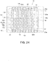
- Fig. 2B is a plan view showing the frame 15.
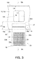
- Fig. 3 is a plan view showing in enlargement a part of the deposition mask 10 shown in Fig. 2A .
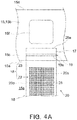
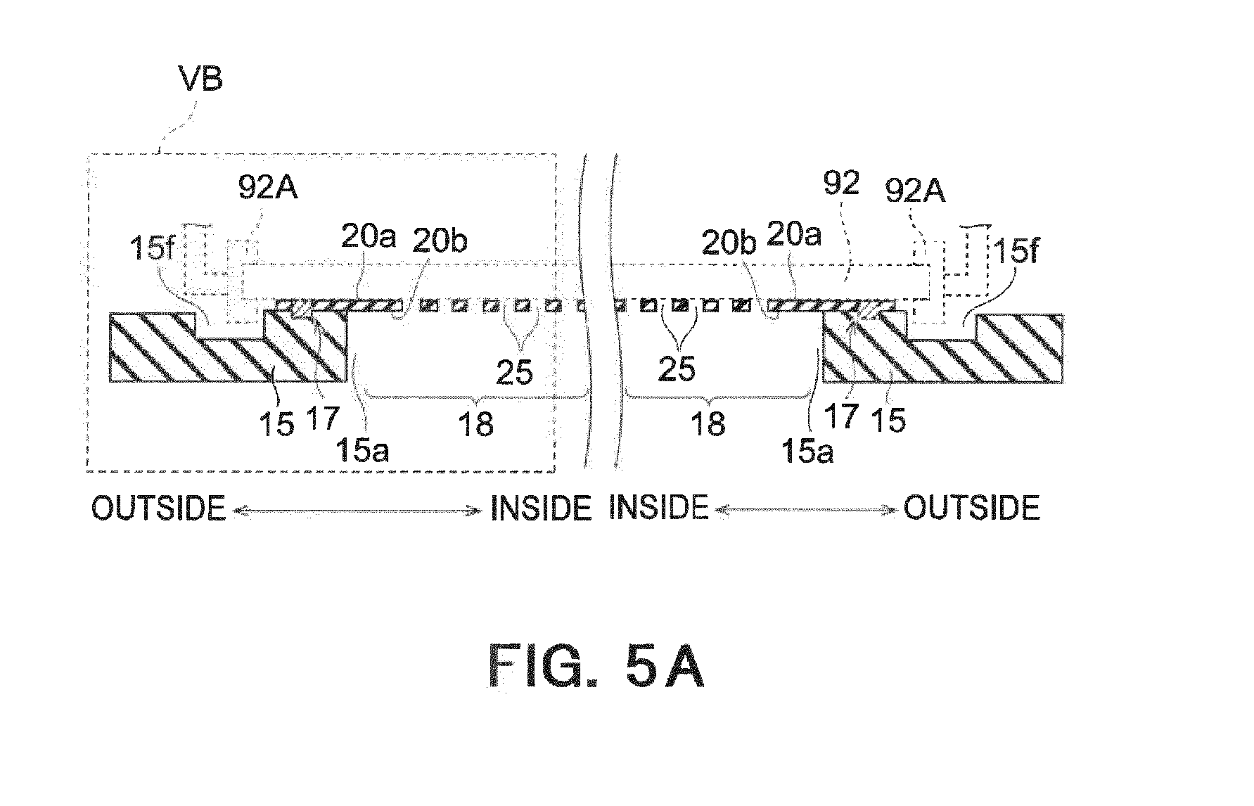
- Fig. 5A is a sectional view of the deposition mask apparatus 10 of Fig. 3 seen from a VA-VA direction.
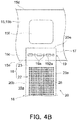
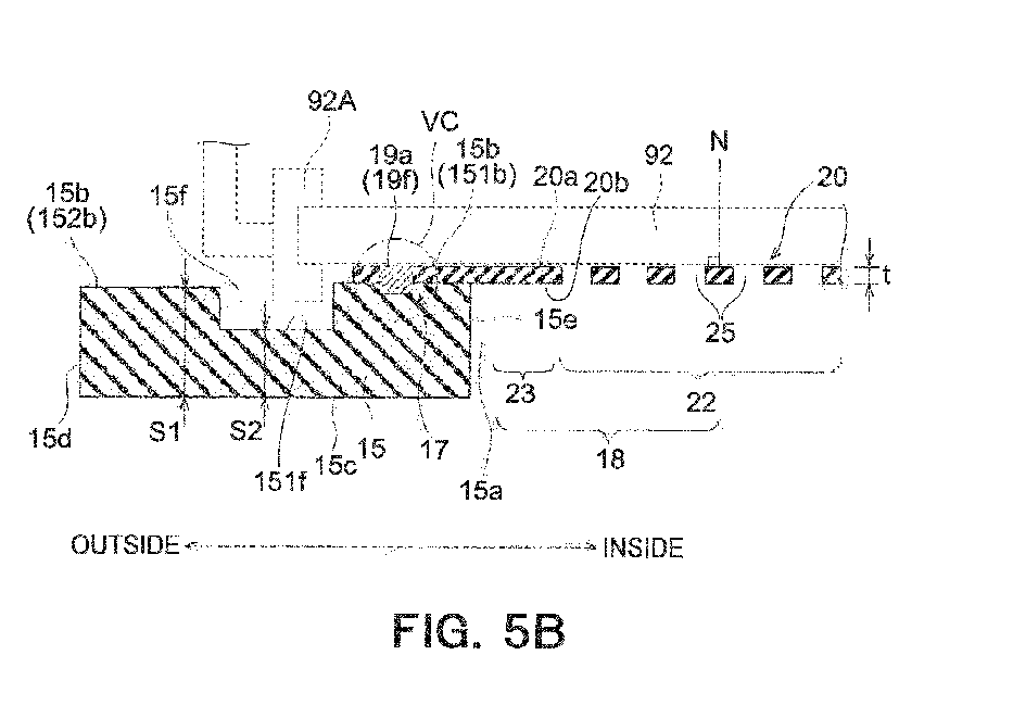
- Fig. 5B is a sectional view showing in enlargement the deposition mask apparatus of Fig. 5A (a sectional view corresponding to a VB part of Fig. 5A .
- Figs. 5A is a sectional view showing in enlargement the deposition mask apparatus of Fig. 5A (a sectional view corresponding to a VB part of Fig. 5A .
- the frame 15 has a front surface 15b (i.e., a third surface) facing the second surface 20b of the deposition mask 20, a rear surface 15c (i.e., a fourth surface) opposed to the front surface 15b, an outside surface 15d spreading between the front surface 15b and the rear surface 15c, and an inside surface 15e spreading between the front surface 15b and the rear surface 15c to face an opening 15a.
- a front surface 15b i.e., a third surface facing the second surface 20b of the deposition mask 20
- a rear surface 15c i.e., a fourth surface
- the front surface 15b and the rear surface 15c when seen in a section along a normal direction N of the first surface 20a of the deposition mask 20, the front surface 15b and the rear surface 15c extend parallel to each other in a direction orthogonal to the normal direction N.
- the outside surface 15d and the inside surface 15e extend in the normal direction N and connect to the front surface 15b and the rear surface 15c orthogonally thereto.
- the deposition material 98 having evaporated from the crucible 94 adheres to the organic EL substrate 92 through the opening 15a of the frame 15.
- the outside surface 15d and the inside surface 15e of the frame 15 may be inclined from the normal direction N or may be curved.
- a plurality of accommodation parts 15f may be formed in the surface 15b of such a frame 15 at positions apart from the opening 15a.
- the plurality of accommodation parts 15f may be posited outside the below-described joint portions 19, and a surface 151f (i.e., a fifth surface) of the accommodation part may be positioned nearer to the rear surface 15c (i.e., the fourth surface) of the frame 15 to the front surface 15b (i.e., the third surface) thereof.
- the accommodation part 15f is configured to be capable of accommodating at least a part of the holding member 92A, when the organic EL substrate 92 held by the holding member 92A is combined with the deposition mask apparatus 10 (see Figs. 5A and 5B ).
- such an accommodation part 15f is constituted by a recess formed in the front surface 15b.
- a front surface 151b of the front surface 15b, which is positioned inside the accommodation part 15f, and a front surface 152b thereof, which is positioned outside the accommodation part 15f, are positioned on the same surface, when seen along the normal direction N of the first surface 20a.
- lowering of strength of the frame 15, which is caused by providing the frame 15 with the accommodation parts 15f, can be prevented. Namely, as compared with a case in which the width of the frame 15 is reduced, a planar dimension of a part of the frame 15, which has the thickness S1 (see Fig. 5B ), can be increased in plan view. Thus, lowering of the strength such as rigidity of the frame 15 can be effectively prevented. As a result, when the frame 15 supports the deposition mask 20 in a taut state, it can be prevented that the frame 15 is deformed such as bent by a force applied from the deposition mask 20. Therefore, the deposition material 98 can be precisely deposited onto the organic EL substrate 92 with the use of the deposition mask 20 supported on the frame 15.
- the reference numeral S2 depicts the thickness of the frame 15 at which the accommodation part 15f is provided.
- the thickness S2 is determined depending on a size of the holding member 92A, in such a manner that the holding member 92A can be prevented from interfering with the frame 15.
- the thickness S2 may be not less than 2 mm, not less than 5 mm, not less than 7 mm, or not less than 10 mm.
- the thickness S2 may be not more than 20 mm, not more than 18 mm, not more than 15 mm, or not more than 12 mm.
- a range of the thickness S2 may be determined by combining any one of the above upper limit candidate values and any one of the above lower limit candidate values.
- the range of the thickness S2 may be not less than 2 mm and not more than 20 mm, not less than 5 mm and not more than 18 mm, not less than 7 mm and not more than 15 mm, or not less than 10 mm and not more than 12 mm.
- the range of the thickness S2 may be determined by combining any two of the above upper limit candidate values.
- the range of the thickness S2 may be not less than 15 mm and not or than 18 mm.
- the range of the thickness S2 may be determined by combining any two of the above lower limit candidate values.
- the range of the thickness S2 may be not less than 7 mm and not more than 10 mm.
- the thickness S1 of a part of the frame 15, which is not provided with the accommodation part 15f, is determined so as to prevent deformation such as bending of the frame 15.
- the thickness S1 may be not less than 5 mm, not less than 10 mm, not less than 15 mm, or not less than 20 mm.
- the range of the thickness S1 may be not more than 35 mm, not more than 30 mm, not more than 25 mm, or not more than 20 mm.
- a range of the thickness S1 may be determined by combining any one of the above upper limit candidate values and any one of the above lower limit candidate values.
- the range of the thickness S1 may be not less than 5 mm and not more than 35 mm, not less than 10 mm and not more than 30 mm, or not less than 15 mm and not more than 25 mm.
- the range of the thickness S1 may be determined by combining any two of the above upper limit candidate values.
- the range of the thickness S1 may be not less than 20 mm and not or than 30 mm.
- the range of the thickness S1 may be determined by combining any two of the above lower limit candidate values.
- the range of the thickness S1 may be not less than 10 mm and not more than 15 mm.
- the thickness S1 may be determined depending on the thickness S2 of the part of the frame 15, which is provided with the accommodation part 15f.
- the thickness S1 may be not less than 1.5 ⁇ S2 and not more than 3.0 ⁇ S2.
- a ratio (referred to also as an accommodation part ratio herebelow) of a planar dimension of the parts (satin-like parts shown in Fig. 2B ) at which the plurality of accommodation parts 15f are provided relative to a whole planar dimension of the front surface 15b of the frame 15 (diagonal-line part shown in Fig. 2B ) is determined so as to prevent the frame 15 from deforming such as bending.
- the accommodation part ratio may be not less than 5%, not less than 7%, or not less than 9%.
- the accommodation part ratio may be not more than 15%, not more than 13%, not more than 9%, or not more than 11%.
- a range of the accommodation part ratio may be determined by combining any one of the above upper limit candidate values and any one of the above lower limit candidate values.
- the range of the accommodation part ratio may be not less than 5% and not more than 15%, not less than 7% and not more than 13%, or not less than 9% and not more than 11%.
- the range of the accommodation part ratio may be determined by combining any two of the above upper limit candidate values.
- the range of the accommodation part ratio may be not less than 11% and not more than 15%.
- the rang of the accommodation part ratio may be determined by combining any two of the above lower limit candidate values.
- the range of the accommodation part ratio may be not less than 5% and not more than 9%.
- the plurality of accommodation parts 15f may be formed between the outside surface 15d and the inside surface 15e.
- the plurality of accommodation parts 15f according to this embodiment are formed outside the pair of ends 20e of the deposition mask 20.
- an area having the thickness S1 can be ensured outside the accommodation parts 15f, whereby lowering of the strength of the frame 15 can be effectively prevented.
- the "outside” means the side which goes away from a centerline CL of the deposition mask 20 in the longitudinal direction of the deposition mask 20.
- the "inside” means the side which comes near to the centerline CL of the deposition mask 20 in the longitudinal direction of the deposition mask 20.
- the centerline CL of the deposition mask is, out of straight lines extending orthogonal to the longitudinal direction of the deposition mask 20, a straight line that passes an intermediate point C (see Fig. 2A ) that bisects a distance between the pair of ends 20e in the longitudinal direction of the deposition mask 20.
- the plurality of accommodation parts 15f are arranged side by side along sides of the opening 15a delimited by the inside surface 15e.
- the opening 15a has a rectangular shape having four sides, and the plurality of accommodation parts 15f are arranged side by side along the pair of sides of the sides of the opening 15a.
- the plurality of deposition masks 20 are attached to the frame 15 such that their ear portions 17 are arranged side by side along the same side of the opening 15a along which the plurality of accommodation parts 15f are arranged side by side.
- the plurality of accommodation parts 15f may be arranged side by side along a side the opening 15a that is different from the side along which the ear portions 17 of the plurality of deposition masks 20 are arranged side by side.
- the number and the dimensions of the accommodation parts 15f can be suitably determined depending on the dimensions of the holding member 92A that holds the organic EL substrate 92, as long as, when the organic EL substrate 92 is installed on the frame 15 (when the organic EL substrate 92 comes into contact with the first surface 20a of the deposition mask 20), the holding member 92A does not come into contact with the accommodation parts 15f.
- a length L1 (length along the longitudinal direction of the deposition mask 20 (see Fig. 3 )) of the accommodation part 15f may be not less than 15 mm and not more than 50 mm, for example, and a width W (length along a width direction of the deposition mask 20 (see Fig.
- the width W may be not less than 5 mm, not less than 10 mm, not less than 15 mm, not less than 20 mm, or not less than 25 mm.
- the width W may be not more than 50 mm, not more than 45 mm, not more than 40 mm, or not more than 35 mm.
- a range of the width W may be determined by combining any one of the above upper limit candidate values and any one of the above lower limit candidate values.
- the range of the width W may be not less than 5 mm and not more than 50 mm, not less than 10 mm and not more than 45 mm, or not less than 15 mm and not more than 40 mm.
- the range of the width W may be determined by combining any two of the above upper limit candidate values.
- the range of the width W may be not less than 35 mm and not more than 45 mm.
- the range of the width W may be determined by combining any two of the above lower limit candidate values.
- the range of the width W may be not less than 10 mm and not more than 20 mm.
- a distance L2 (see Fig. 2A ) between the accommodation parts 15f adjacent to each other may, for example, be not less than 50 mm, not less than 80 mm, not less than 100 mm, or not less than 130 mm.
- the distance L2 may be not more than 250 mm, not more than 220 mm, not more than 200, or not more than 180 mm.
- a range of the distance L2 may be determined by combining any one of the above upper limit candidate values and any one of the above lower limit candidate values.
- the range of the distance L2 may be not less than 50 mm and not more than 250 mm, not less than 80 mm and not more than 220 mm, or not less than 100 mm and not more than 200.
- the range of the distance L2 may be determined by combining any two of the above upper limit candidate values.
- the range of the distance L2 may be not less than 200 and not more than 220.
- the range of the distance L2 may be determined by combining any two of the above lower limit candidate values.
- the range of the distance L2 may be nor less than 130 mm and not more than 150 mm.
- a cycle of the plurality of accommodation parts 15f arranged side by side along the side of the opening 15a corresponds to a cycle of the plurality of deposition masks 20 arranged side by side along the same side of the opening 15a, but the present invention is not limited thereto.
- the cycle of the plurality of accommodation parts 15f may differ from the cycle of the plurality of deposition masks 20.
- a distance L3 (see Fig. 3 ) from the inside surface 15e of the frame 15 to the accommodation part 15f may be, for example, not less than 1 mm and not more than 20 mm, and preferably not less than 3 mm and not more than 20 mm.
- a planar dimension of the joint portion 19 an be sufficiently ensured, whereby the strength of the joint portion 19 can be increased.
- a planer dimension of the opening 15a can be enlarged, whereby an area effective to deposition can be enlarged.
- the distance L3 from the inside surface 15e of the frame 15 to the accommodation part 15f may be ,for example, not less than 1 mm, not less than 3 mm, not less than 5 mm, or not less than 10 mm.
- the distance L3 may be not more than 20 mm, not more than 18 mm, or not more than 15 mm.
- a range of the distance L3 may be determined by combining any one of the above upper limit candidate values and any one of the above lower limit candidate values.
- the range of the distance L3 may be not less than 1 mm and not more than 20 mm, not less than 3 mm and not more than 18 mm, or not less than 5 mm and not more than 15 mm.
- the range of the distance L3 may be determined by combining any two of the above upper limit candidate values.
- the range of the distance L3 may be not less than 15 mm and not more than 18 mm.
- the range of the distance L3 may be determined by combining any two of the above lower limit candidate values.
- the range of the distance L3 may be not less than 3 mm and not more than 10 mm.
- a distance L4 (see Fig. 3 ) from the outside surface 15d of the frame 15 to the accommodation part 15f may be, for example, not less than 10 mm and not more than 80 mm, preferably not less than 30 mm.
- the distance L4 from the outside surface 15d of the frame 15 to the accommodation part 15f may be, for example, not less than 10 mm, not less than 20 mm, not less than 30 mm, or not less than 40 mm.
- the distance L4 from the outside surface 15d of the frame 15 to the accommodation part 15f may be not more than 80 mm, not more than 70 mm, not more than 60 mm, or not more than 50 mm.
- a range of the distance L4 may be determined by combining any one of the above upper limit candidate values and any one of the above lower limit candidate values.
- the distance L4 may be not less than 10 mm and not more than 80 mm, not less than 20 mm and not more than 70 mm, or not less than 30 mm and not more than 60 mm.
- the range of the distance L4 may be determined by combining any two of the above upper limit candidate values.
- the range of the distance L4 may be not less than 50 mm and not more than 80 mm.
- the range of the distance L4 may be determined by combining any two of the above lower limit candidate values.
- the range of the distance L4 may be not less than 10 mm and not more than 40 mm.
- the accommodation part 15f has a rectangular shape in plan view.
- the accommodation part 15f may have any shape, for example, a circular shape or an elliptic shape in plan view, or a polygonal shape such as a hexagonal shape or an octagonal shape.
- the respective accommodation parts 15f may have shapes different from one another.
- the accommodation parts 15f may respectively have a circular shape, an elliptic shape, or a polygonal shape such as a hexagonal shape or an octagonal shape in plan view.
- such a accommodation part 15f may pass through the frame 15. In this case, there may be formed an accommodation part 15f that passes through the frame 15, and an accommodation part 15f that does not pass through the frame 15.
- the deposition mask 20 comprises a pair of ear portions 17 that constitute a pair of ends 20e in the longitudinal direction of the deposition mask 20, and an intermediate portion 18 that is posited between the pair of ear portions 17.
- the ear portion 17 is a part of the deposition mask 20, which is fixed to the frame 15.
- the ear portion 17 is fixed to the frame 15 by welding, on the side of the second surface 20b.
- a part of the ear portion 17 and a part of the frame 15, which are joined to each other by welding are referred to as a joint portion 19.
- the joint portion 19 may be positioned between the opening 15a of the aforementioned frame 15 and the accommodation part 15f.
- the joint portion 19 formed in the ear portion 17 includes a welding taint 19a.
- the welding taint 19a is a trace formed in the first surface 20a of the deposition mask 20, which is caused by welding the second surface 20b of the deposition mask 20 to the frame 15.
- the joint portion 19 includes a plurality of dot-like welding taints 19a arranged side by side along the width direction of the deposition mask 20.
- Such plurality of dot-like welding taints 19a are formed by intermittently applying a laser beam like dots to the ear portion 17 at respective positions along the width direction of the deposition mask 20.
- the welding taint 19a may extend linearly along the width direction of the deposition mask 20.
- such welding taint 19a may be formed by continuously applying a laser beam like a line to the ear portion 17 at respective positions along the width direction of the deposition mask 20.
- the welding strength can be increased.
- the welding taint 19a may include a first welding taint 191a formed like a dot and a second welding taint 192a formed like a line.
- the welding taint 19a includes a plurality of first welding taints 191a and a plurality of second welding taints 192a.
- the first welding taints 191a and the second welding taints 192a are regularly, i.e., alternately arranged among the width direction of the deposition mask 20.
- the shapes of the respective second welding taints 192 may be overlapped with each other, for example.
- the number of the first welding taint 191a may be only one, and the number of the second welding taint 192a may be only one. Also in this case, since the welding taint 19a includes the linearly formed second welding taint 192a, the welding strength can be increased.
- the first welding taints 191a and the second welding taints 192a may be irregularly arranged along the width direction of the deposition mask 20.
- the numbers of the first welding taints 191a arranged between the second welding taints 192a adjacent to each other in the width direction of the deposition mask 20 differ from each other.
- the shapes of the respective second welding taints 192a may differ from each other, for example.
- the numbers of the first welding taints 191a arranged between the second welding taints 192a adjacent to each other in the width direction of the deposition mask 20 are optional.
- the density of the welding taints 19a can be selectively increased at a part where the welding density of the deposition mask 20 is desired to be increased.
- a plurality of dot-like welding taints 19a may be formed in a plurality of rows along the width direction of the deposition mask 20.
- the welding taints 19a are formed in two rows along the width direction of the deposition mask 20.
- the welding taints 19a may be formed in three rows or in four rows along the width direction of the deposition mask 20. In this case, since the plurality of dot-like welding taints 19a are formed in a plurality of rows along the width direction of the deposition mask, the welding strength can be increased.
- the welding taint 19a may be formed like a frame along the width direction of the deposition mask 20. Also in this case, since the welding taint 19a is formed along the width direction of the deposition mask 20, the welding strength can be increased.
- the welding taint 19a extends from the first surface 20a of the ear portion 17 to reach the frame 15 through the second surface 20b.
- the welding taint 19a is a part of the ear portion 17 of the deposition mask and the frame 15, which was melted (i.e., melted area 19f) upon welding and is then solidified, and includes a part of the ear portion 17, which extends from the first surface 20a to reach the second surface 20b, and a part of the frame 15.
- the welding taint 19a joins the ear portion 17 of the deposition mask 20 and the frame 15 to each other.
- the welding taint 19a when a temperature of the melt area 19f lowers after welding so that the melt area 19f solidifies, a material crystallizes.
- the welding taint 19a includes crystal grains striding the ear portion 17 and frame 15.
- the welding taint 19 may be formed to project from the first surface 20a of the deposition mask 20.
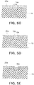
- the welding taint 19a may be formed such that an upper surface 19b of the welding taint 19a is positioned on the same plane as that of the first surface 20a of the deposition mask 20. Further, as shown in Fig. 5E , the welding taint 19a may be recessed toward the second surface 20b with respect to the first surface 20a of the deposition mask 20. In these cases, when the deposition material 98 is deposited onto the organic EL substrate 92, adhesion between the deposition mask 20 and the organic EL substrate 92 can be improved.
- the organic EL substrate 92 which is in tight contact with the deposition mask 20 during the deposition process, is shown by dotted lines. As shown in Figs. 5A and 5B , in this embodiment, the organic EL substrate 92 extends outside a part of the deposition mask 20, at which the joint portion 19 is formed. In addition, when the organic EL substrate 92 is installed on the frame 15, the organic EL substrate 92 is installed on the frame 15 while it is being held by the holding member 92A. The holding member 92A may be detached from the organic EL substrate 92, when the deposition material 98 is deposited onto the organic EL substrate 92.
- the ear portion 17 is cut between the opening 15a of the frame 15 and the accommodation part 15f so as to be partly removed.
- the pair of ends 20e in the longitudinal direction of the deposition mask 20 are positioned between the opening 15a of the frame 15 and the accommodation parts 15f.
- the intermediate portion 18 includes an effective area 22 in which the through-holes 25 extending from the first surface 20a to reach the second surface 20b are formed, and a peripheral area 23 surrounding the effective area 22.
- the peripheral area 23 is an area for supporting the effective area 22, and is not an area through which the deposition material, which is intended to be deposited onto the organic EL substrate 92, passes.
- the effective area 22 is an area of the deposition mask 20, which faces a display area of the organic EL substrate 92.
- the effective area 22 has a profile of a substantially quadrangular shape in plan view, more precisely a substantially rectangular shape in plan view.
- each effective area 22 may have a profile of various shapes depending on a shape of the display area of the organic EL substrate 92.
- each effective area 22 may have a profile of a circular shape.
- the intermediate portion 18 includes a plurality of effective areas 22 that are arranged at predetermined intervals therebetween along the longitudinal direction of the deposition mask 20.
- One effective area 22 corresponds to a display area of one organic EL display device 100.
- the deposition mask apparatus 10 shown in Fig. 1A enables a multifaceted deposition of the organic EL display devices 100.
- Fig. 6 is a plan view showing in enlargement the intermediate portion 18.
- Fig. 7 is a sectional view of the intermediate portion 18 of Fig. 6 seen from the VII-VII direction.
- the plurality of through-holes 25 are arranged in the effective area 22 at predetermined pitches along two directions orthogonal to each other.
- Fig. 6 is a plan view showing in enlargement the effective area 22 from the side of the second surface 20b of the deposition mask 20. As shown in Fig. 6 , in the illustrated example, the plurality of through-holes 25 formed in each effective area 22 are arranged at predetermined pitches along two directions orthogonal to each other.
- Fig. 7 is a sectional view along the VII- VII direction of the effective area 22 of Fig. 6 .
- the plurality of through-holes 25 pass through the deposition mask 20 from the first surface 20a of the deposition mask 20 to the second surface 20b thereof.
- first recesses 30 are formed by etching in a first surface 64a of a metal plate 64, which is one side in the normal direction N of the first surface 20a of the deposition mask 20.
- Second recesses 35 are formed in a second surface 64b of the metal plate e64, which is the other side in the normal direction N.
- the through-hole 25 is composed of the second recess 35 and the first recess 30 connected to the second recess 35. As shown in Figs. 6 and 7 , a wall surface 31 of the first recess 30 and a wall surface 36 of the second recess 35 are connected through a circumferential hole connection portion 41.
- the connection portion 41 defines a through-portion 42 at which a planar dimension of the through-hole 25 is minimum in plan view of the deposition mask 20.
- the adjacent two through-holes 25 in the first surface 20a of the deposition mask 20 are spaced apart from each other along the first surface 64a of the metal plate 64.
- the adjacent two through second recesses 35 may be spaced apart from each other along the second surface 64b of the metal plate 64. Namely, the second surface 64b of the metal plate 64 may remain between the adjacent two second recesses 35.
- this portion of the effective area 22 of the second surface 64b of the metal plate 64 which is not etched and thus remains, is also referred to as a top portion 43.
- the deposition mask 20 is damaged during conveyance, for example.
- a width ⁇ of the top portion 43 is too large, there is a possibility that shadow occurs in the deposition step, which lowers utilization efficiency of the deposition material 98.
- the deposition mask 20 is preferably manufactured such that the width ⁇ of the top portion 43 is excessively large.
- the first surface of the deposition mask 20 faces the organic EL substrate 92 as shown by two-dot chain lines in Fig. 7 , and the second surface 20b of the deposition mask 20 is positioned on the side of the crucible 94 holding the deposition material 98.
- the deposition material 98 adheres to the organic EL substrate 92 through the second recess 35 whose opening area gradually decreases. As indicated by the arrow in Fig.
- the deposition material 98 not only moves from the crucible 94 toward the organic EL substrate 92 along the normal direction N of the organic EL substrate 92, but also sometimes moves along a direction largely inclined with respect to the normal direction N of the organic EL substrate 92.
- the thickness of the deposition mask 20 is large, most of the diagonally moving deposition material 98 reaches the wall surface 36 of the second recess 35 to adhere thereto, before the deposition material 98 passes through the through-holes 25 to reach the organic EL substrate 92.
- the thickness t of the deposition mask 20 is reduced so that heights of the wall surface 36 of the second recess 35 and the wall surface 31 of the first recess 30 are reduced. Namely, it can be said that it is preferable to use the metal plate e64, which has the thickness t as small as possible, as long as the strength of the deposition mask 20 is ensured.
- the thickness t of the deposition mask 20 is, for example, not more than 30 ⁇ m), preferably not more than 25 ⁇ m, or further preferably not more than 20 ⁇ m.
- the thickness t of the deposition mask 20 is preferably not less than 5 ⁇ m.
- the thickness t of the deposition mask may be not less than 8 ⁇ m, to less than 10 ⁇ m, not less than 12 ⁇ mm, not less than 13 ⁇ m or not less than 15 ⁇ m.
- a range of the thickness t may be determined by combining any one of the above upper limit candidate values and any one of the above lower limit candidate values.
- the range of the thickness t of the deposition mask 20 may be not less than 13 ⁇ m and not more than 15 ⁇ m.
- the thickness t is a thickness of the peripheral area 23, i.e., a portion of the deposition mask 20, at which no first recess 30 and no second recess 35 is formed.
- the thickness t is a thickness of the metal plate 64.
- a minimum angle defined by a line L5, which passes the connection portion 31 having the minimum opening area of the through-hole 25 and another given position of the wall surface 36 of the second recess 35, with respect to the normal direction N of the deposition mask 20 is represented by a reference numeral ⁇ 1.
- the angle ⁇ 1 is increased. In order to increase the angle ⁇ 1, it is effective to reduce the aforementioned width ⁇ of the top portion 43, as well as to reduce the thickness t of the deposition mask 20.
- the reference numeral ⁇ represents a width of a portion (hereinafter referred to also as "rib portion") of the effective area 22 of the first surface 64a of the metal plate 64, which is not etched and thus remains.
- a width ⁇ of the rib portion and a size r of the through-portion 42 are suitably determined depending on a size of an organic EL display device and the number of display pixels.
- the width ⁇ of the rib portion is not less than 5 ⁇ m and not more than 40 ⁇ m
- the size r of the through-portion 42 is not less than 10 ⁇ m and not more than 60 ⁇ m.
- the second surface 64b of the metal plate 64 remains between the adjacent two second recesses 35, but the present invention is not limited thereto.
- etching may be performed so that the adjacent two second recesses 35 are connected to each other. Namely, there may be a part where no second surface 64b of the metal plate 64 remains between the adjacent two second recesses 35.
- a method of manufacturing the deposition mask 20 is described with reference mainly to Figs. 8 to 11 .
- a plurality of through-holes 25 corresponding to the plurality of deposition masks 20 are formed in the metal plate 64.
- the plurality of deposition masks 20 are allocated to the metal plate 64.
- a first resist pattern 65a can be formed on the first surface 64a of the metal plate 64
- a second resist pattern 65b can be formed on the second surface 64b of the metal plate 64.
- a first-surface etching step is performed, in which areas of the first surface 64a of the metal plate 64, which are not covered with the first resist pattern 65a, are etched by using a first etchant.
- a first etchant to be used is an etchant containing ferric chloride solution and hydrochloric acid, for example.
- a second-surface etching step is performed, in which areas of the second surface 64b of the metal plate 64, which are not covered with the second resist pattern 65b, are etched so as to form the second recesses 35 in the second surface 64b.
- the second etching step is performed until the first recess 30 and the second recess 35 are communicated with each other so as to form the through-hole 25.
- a second etchant may be an etchant containing ferric chloride solution and hydrochloric acid, for example.
- the first recesses 30 may be coated with a resin 69 resistant to the second etchant.
- the resin 69 is removed from the metal plate 64.
- the resin 69 can be removed by using an alkali-based peeling liquid.
- the resist patterns 65a, 65b are removed simultaneously with the removal of the resin 69.
- the resist patterns 65a, 65b may be removed separately from the resin 69.
- the deposition mask 20 can be obtained.
- a metal plate 150 is prepared.
- the frame 15 has a front surface 15b, a rear surface 15c opposed to the front surface 15b, an outside surface 15d spreading between the front surface 15b and the rear surface 15c, and an inside surface 15e spreading between the front surface 15b and the rear surface 15c at a position inside of the outside surface 15d, and facing an opening 15a.
- a plurality of accommodation parts 15f are formed at positions apart from the opening 15a in the front surface 15b of the frame 15. In this manner, the frame 15 is manufactured.
- the frame 15 may be manufactured with the use of a mold or a 3D printer.
- the deposition mask apparatus 10 comprising the deposition masks 20 and the frame 15 can be obtained.
- the deposition mask 20 is placed on the frame 15. Then, by a welding apparatus, not shown, a laser beam is applied from the side of the first surface 20a of the deposition mask 20.
- a part of the ear portion 17 of the deposition mask 20 and a part of the frame 15 are melt so that a melted area 19f, which extends from the first surface 20a of the ear portion 17 to reach the frame 15 through the second surface 20b, is formed.
- the melted area 19f strides over the ear portion 17 and the frame 15.
- a YAG laser beam generated by a YAG laser system can be used.
- a YAG layer system a system including a crystal of YAG (yttrium aluminum garnet) doped with Nd (neodymium) as an oscillation medium can be used.
- laser light with a wavelength of about 1064 nm is generated as the fundamental.
- a second harmonic with a wavelength of about 532 nm is produced by passing the fundamental through a nonlinear optical crystal.
- a third harmonic with a wavelength of about 355 nm is produced by passing the fundamental and second harmonic through a nonlinear optical crystal.
- the third harmonic of YAG laser light is likely to be absorbed by an iron alloy containing nickel.
- the laser beam preferably includes the third harmonic of YAG laser light.
- the temperature of the melted area 19f lowers, so that the melted area 19f solidifies into the welding taint 19a.
- the ear portion 17 of the deposition mask 20 and the frame are joined to each other by means of the welding taint 19a.
- the ear portion of the deposition mask 20 is cut between the opening 15a of the frame 15 and the accommodation parts 15f, so that a part of the ear portion 17 is removed.
- the deposition mask apparatus 10 obtained by the aforementioned steps is prepared. Namely, as shown in Fig. 13A , the deposition apparatus, which comprises the deposition mask apparatus 10, the crucible 94 containing the deposition material 98, and the heater 96, is prepared.
- the organic EL substrate 92 is positioned and placed on the frame 15.
- the organic the organic EL substrate 92 is positioned such that these alignment marks are overlapped with each other.
- center position coordinates of the alignment mark of the organic EL substrate 92 and center position coordinates of the alignment mark of the deposition mask 20 may be separately measured, and the organic EL substrate 92 is positioned such that these center position coordinates have a predetermined positional relationship.
- the plurality of accommodation parts 15f capable of accommodating at least a part of the holding member 92A are discretely provided in the front surface 15b of the frame 15.
- parts of the frame 15, each of which has a thickness S1 and is free of the accommodation part 15f can be distributed over all the area of the frame 15.
- lowering of strength of the frame 15, which is caused by providing the frame 15 with the accommodation parts 15f can be prevented.
- the deposition material 98 can be precisely deposited onto the organic EL substrate 92 with the use of the deposition mask 20 supported on the frame 15.
- the plurality of accommodation parts 15f are formed between the outside surface 15d and the inside surface 15e.
- an area having the thickness S1 can be ensured outside the accommodation parts 15f, whereby lowering of the strength of the frame 15 can be effectively prevented.
- the deposition material 98 is deposited onto the organic EL substrate 92 installed on the frame 15.
- a magnet 93 is disposed on a surface of the organic EL substrate 92, which is opposed to the deposition mask 20.
- the deposition mask 20 is attracted toward the magnet 93 by a magnetic force, so that the deposition mask 20 can be brought into tight contact with the organic EL substrate 92.
- the heater 96 heats the crucible 94 to evaporate the deposition material 98.
- the deposition material 98 evaporated from the crucible 94 to reach the deposition mask apparatus 10 adheres to the organic EL substrate 92 through the through-holes 25 of the deposition mask 20 (see Fig. 1A ). At this time, the holding member 92A may be removed from the organic EL substrate 92.
- the deposition material 98 can be deposited onto the organic EL substrate 92 in a desired pattern corresponding to the positions of the through-holes 25 of the deposition mask 20.
- the plurality of accommodation parts 15a capable of accommodating at least a part of the holding member 92A are formed at positions of the front surface 15b of the frame 15 apart from the opening 15a.
- the holding member 92A can be prevented from interfering with the frame 15.
- the accommodation parts 15f are formed at positions apart from the opening 15a, the joint portion 19 can be ensured, whereby the welding strength of the joint portion 19 of the deposition mask 20 can be increased.
- the plurality of accommodation parts 15f are formed in the front surface 15f of the frame 15.
- an area having the thickness S1 can be ensured between the plurality of accommodation parts 15f, and parts of the frame 15, each of which has a thickness S1 and is free of the accommodation part 15f, can be distributed over all the area of the frame 15.
- lowering of strength of the frame 15, which is caused by providing the frame 15 with the accommodation parts 15f can be prevented.
- the frame 15 is deformed such as bent by a force applied from the deposition mask 20. Therefore, the deposition material 98 can be precisely deposited onto the organic EL substrate 92 with the use of the deposition mask 20 supported on the frame 15.
- the plurality of accommodation parts 15f are formed between the opening 15a and the outside surface 15d.
- an area having the thickness S1 can be ensured outside the accommodation parts 15f, whereby lowering of the strength of the frame 15 can be effectively prevented.
- the deposition mask 20 is manufactured by etching.
- a method employed for manufacturing the deposition mask 20 is not limited to etching.
- the deposition mask 20 can be manufactured by forming the through-holes 25 in a metal plate by a plating process.
- the thickness of the ear portion 17 of the deposition mask 20 and the thickness of the intermediate portion 18 are the same with each other.
- the thickness of the ear portion 17 and the thickness of the intermediate portion 18 may differ from each other.
- the thickness of the ear portion 17 may be greater than the thickness of the intermediate portion 18.
- the thickness of the ear portion 17 may be smaller than the thickness of the intermediate portion 18, for example.
- the example in which the plurality of accommodation parts 15f of the frame 15 are formed between the opening 15a and the outside surface 15d is described.
- the plurality of accommodation parts 15f may extend to reach the outside surface 15d. Also in this case, since the plurality of accommodation parts 15f are provided to be spaced apart from each other, lowering of the strength of the frame 15 can be prevented.
- the plurality of accommodation parts 15f of the frame 15 are formed between the opening 15a and the outside surface 15d is described.
- the plurality of accommodation parts 15f may be formed to surround the opening 15a.
- the opening 15a may have a rectangular shape having four sides, and the plurality of accommodation parts 15f may be arranged side by side along the four sides of the opening 15a.
- the holding member 92A may hold the four sides of the organic EL substrate 92.
- the holding member 92A holds the four sides of the organic EL substrate 92.
- entering of air between the organic EL substrate 92 and the deposition mask 20 can be prevented.
- the organic EL substrate 92 bends by this own weight such that a part near the center of the organic EL substrate 92 is positioned most downward.
- the organic EL substrate 92 when the organic EL substrate 92 comes into contact with the deposition mask 20, the organic EL substrate 92 can be brought into contact with the deposition mask 20 such that the organic EL substrate 92 and the deposition mask 20 are in point contact with each other.
- the organic EL substrate 92 By gradually lowering the organic EL substrate 92 while the holding member 92A holds the four sides of the organic EL substrate 92, entering of air between the organic EL substrate 92 and the deposition mask 20 can be prevented.
- bending of the organic EL substrate 92 in the step of installing the organic EL substrate 92 on the frame 15, bending of the organic EL substrate 92 can be reduced, so that the organic EL substrate 92 can be stably transported. At the same time, risk of damage of the organic EL substrate 92 can be reduced.
- the organic EL substrate 92 can be stably transported, and the risk of damage of the organic EL substrate 92 can be reduced.
- no accommodation part 15f may be provided in four corners of the frame 15.
- the four corners of the frame 15 mean areas surrounded by virtual lines X obtained by extending the four sides of the opening 15a to reach the outside surface 15d of the frame 15 and the outside surface 15d in plan view (satin-like areas in Fig. 17C ).
- the frame 15 is provided with an alignment mark M for positioning the deposition mask 20 when the deposition mask 20 is joined to the frame 15.
- the alignment mark M is provided at a position that is not overlapped with the deposition mask 20 in plan view, after the deposition mask 20 has been joined to the frame 15.
- the alignment marks M are preferably provided on four corners of the frame 15.
- the alignment marks M can be reliably formed on four corners of the frame 15, whereby the deposition mask 20 can be easily positioned.
- the deposition mask apparatus 10 uses the plurality of deposition masks 20 that are allocated to the frame 15 .
- the deposition mask apparatus 10 may use a single deposition mask 20 having a plurality of effective areas 22 that are arranged like a grid.
- the front surface 15b of the frame 15 may include a first front surface 15g positioned closer to the inside surface 15e and a second front surface (i.e., fifth surface) 15h positioned closer to the outside surface 15d and positioned closer to the rear surface 15c than the first front surface 15g, the first front surface 15g and the second front surface 15h may be connected to each other through an intermediate surface 15i, and the accommodation parts 15f may be formed in the first front surface 15g that extend to reach the intermediate surface 15i.
- a thickness from the second front surface 15h to the rear surface 15c is uniformly small as compared with a thickness from the first front surface 15g to the rear surface 15c.
- the reference numeral S3 depicts a thickness from the second front surface 15g to the rear surface 15c
- the reference numeral S4 depicts a thickness from the first front surface 15h to the rear surface 15c.
- the thickness S4 is determined depending on the size of the holding member 92A such that the holding member 92A can be prevented from interfering with the frame 15.
- the thickness S4 may be not less than 2 mm, not less than 5 mm, not les than 7 mm, or not less than 10 mm.
- the thickness S4 may be not more than 20 mm, not more than 18 mm, not more than 15 mm, or not more than 12 mm.
- a range of the thickness S4 may be determined by combining any one of the above upper limit candidate values and any one of the above lower limit candidate values.
- the range of the thickness S4 may be not less than 2 mm and not more than 20 mm, not less than 5 mm and not more than 18 mm, not less than 7 mm and not more than 15 mm, or not less than 10 mm and not more than 12 mm.
- the range of the thickness S4 may be determined by combining any two of the above upper limit candidate values.
- the range of the thickness S4 may be not less than 15 mm and not more than 18 mm.
- the range of the thickness S4 may be determined by combining any two of the above lower limit candidate values.
- the range of the thickness S4 may be not less than 7 mm and not more than 10 mm.
- the thickness S3 from the first front surface 15g to the rear surface 15c is determined to prevent the frame 15 from deforming such as bending.
- the thickness S3 may be not less than 5 mm, not less than 10 mm, not less than 15 mm or not less than 20 mm.
- the thickness S3 may be not more than 35 mm, not more than 30 mm, not more than 25 mm, or not more than 20 mm.
- a range of the thickness S3 may be determined by combining any one of the above upper limit candidate values and any one of the above lower limit candidate values.
- the range of the thickness S3 may be not less than 5 mm and not more than 35 mm, not less than 10 mm and not more than 30 mm, or not less than 15 mm and not more than 25 mm.
- the range of the thickness S3 may be determined by combining any two of the above upper limit candidate values.
- the range of the thickness S3 may be not less than 20 mm and not more than 30 mm.
- the range of the thickness S3 may be determined by combining any two of the above lower limit candidate values.
- the range of the thickness S3 may be not less than 10 mm and not more than 15 mm.
- the thickness S3 may be determined depending on the thickness S4 from the second front surface 15h to the rear surface 15c.
- the thickness S4 may be not less than 1.5 ⁇ S4 and not more than 3.0 ⁇ S4.
- the ratio (accommodation part ratio) of a planar dimension of a part of the first front surface 15g of the frame 15, in which the plurality of accommodation parts 15f are provided is determined so as to prevent the frame 15 from deforming such as bending.
- the accommodation part ratio may be not less than 5%, not less than 7%, or not less than 9%.
- the accommodation part ratio may be not more than 15%, not more than 13%, not more than 9%, or not more than 11%.
- a range of the accommodation part ratio may be determined by combining any one of the above upper limit candidate values and any one of the above lower limit candidate values.
- the range of the accommodation part ratio may be not less than 5% and not more than 15%, not less than 7% and not more than 13%, or not less than 9% and not more than 11%.
- the range of the accommodation part ratio may be determined by combining any two of the above upper limit candidate values.
- the range of the accommodation part ratio may be not less than 11% and not more than 15%.
- the rang of the accommodation part ratio may be determined by combining any two of the above lower limit candidate values.
- the range of the accommodation part ratio may be not less than 5% and not more than 9%.
- the organic EL substrate 92 on the deposition mask apparatus 10 such that the accommodation parts 15f accommodate at least a part of the holding member 92A or that the holding member 92A is positioned on the second front surface 15h of the frame 15, it can be prevented that the holding member 92A from interfering with the frame 15.
- the plurality of accommodation parts 15f may be formed inside the pair of ends 20e of the deposition mask 20.
- the plurality of accommodation parts 15f may be formed inside the pair of ends 20e of the deposition mask 20.
- all of the respective accommodation parts 15f may be formed inside the pair of ends 20e of the deposition mask 20, or only some of the respective accommodation parts 15f may be formed inside the pair of ends 20e of the deposition mask 20.
- the plurality of accommodation parts 15f are discretely provided in the front surface 15b of the frame 15 so as to be positioned between the plurality of deposition masks 20.
- the organic EL substrate 92 may not extend outside a part of the deposition mask 20, at which the joint portion 19 is formed, but may be positioned inside the part at which the joint portion 19 is formed.
- the deposition mask 20 As described above, after the deposition mask 20 has been welded to the frame 15, a part of the ear portion 17 is removed. Thus, in the pair of ends 20e of the deposition mask 20, there is a possibility that burr occurs by cutting. When burr occurs in the pair of ends 20e, adhesion between the deposition mask 20 and the organic EL substrate 92 is lowered by the burr, which may result in defective deposition.
- the plurality of accommodation parts 15f are discretely provided in the front surface 15b of the frame 15, such that the plurality of accommodation parts 15f are formed inside the pair of ends 20e of the deposition mask 20 and are positioned between the plurality of deposition masks 20.
- the organic EL substrate 92 can be positioned inside the part of the deposition mask 20, at which the joint portion 19 is formed, so that it can be prevented that the organic EL substrate 92 overlaps with the pair of ends 20e of the deposition mask 20.
- lowering of adhesion between the deposition mask 20 and the organic EL substrate 92 by the burr can be prevented, whereby defective deposition can be avoided.
- the example in which the front surface 151b of the front surface 15b of the frame 15, which is positioned inside the accommodation part 15f, and the front surface 152b thereof, which is positioned outside the accommodation part 15f, are positioned on the same surface, when seen along the normal direction N of the first surface 20a.
- the present invention is not limited thereto.
- the frame 15 may have various shapes.
- the front surface 152b of the front surface 15b of the frame 15, which is positioned outside the accommodation part 15f may be positioned closer to the deposition mask 20 than the front surface 151b thereof, which is positioned inside the accommodation part 15f.
- a thickness of a part of the frame 15, which is positioned outside the accommodation part 15f can be increased, so that the strength of the frame 15 can be increased.
- the front surface 151b of the front surface 15b of the frame 15, which is positioned inside the accommodation part 15f may be positioned closer to the deposition mask 20 than the front surface 152b thereof, which is positioned outside the accommodation part 15f. Also in this case, it can be prevented that the holding member 92A from interfering with the frame 15.
- a part of the front surface 152b of the front surface 15b of the frame 15, which is positioned outside the accommodation part 15f, may be inclined toward the rear surface 15c of the frame 15 as it goes outward, when seen along the normal direction N of the first surface 20a.
- a part of the front surface 152b of the front surface 15b of the frame 15, which positioned outside the accommodation part 15f may have a curvilinear shape, when seen along the normal direction of the first surface 20a. Also in this case, it can be prevented that the holding member 92A from interfering with the frame 15.
- the accommodation part 15f may extend to reach the outside surface 15d, and the surface 151f of the accommodation part 15f may be inclined toward the deposition mask 20 as it goes outward.
- an end of the accommodation part 15f when seen along the normal direction N of the first surface 20a, an end of the accommodation part 15f may be positioned on the same plane as the front surface 151b of the front surface 15b of the frame 15, which positioned inside the accommodation part 15f.
- the end of the accommodation part 15f may be positioned closer to the deposition mask 20 than the front surface 151b of the front surface 15b of the frame 15, which positioned inside the accommodation part 15f.
- a part of the surface 151f (i.e., fifth surface) of the accommodation part 15f may be positioned closer to the deposition mask 20 than the front surface 151b of the front surface 15b of the frame 15, which positioned inside the accommodation part 15f.
- a part of the surface 151f (i.e., fifth surface) of the accommodation part 15f may be positioned closer to the rear surface 15c of the frame 15 than the front surface 151b. Also in this case, it can be prevented that the holding member 92A from interfering with the frame 15.
- the accommodation part 15f may include an inclined portion (see dotted lines in Fig. 23H ) 152f which is inclined toward the deposition mask 20 as it goes inward.
- the thickness of the frame 15 can be increased, whereby the strength of the frame 15 an be increased.
- the plurality of accommodation parts 15f may extend to reach the outside surface 15d. Also in this case, at the accommodation part 15f of the frame 15, the thickness of the frame 15 can be increased, whereby the strength of the frame 15 an be increased.
- Fig. 23H the accommodation part 15f of the frame 15 can be increased, whereby the strength of the frame 15 an be increased.
- the inclined portion 152f when seen along the normal direction N of the first surface 20a, the inclined portion 152f may be formed to smoothly connect to the front surface 15b of the frame 15 and the surface 151f of the accommodation part 15f.
- the inclined portion 152f when seen along the normal direction N of the first surface 20a , the inclined portion 152f may have a wavelike form.
- the inclined portion 152f when seen along the normal direction N of the first surface 20a, may have a curvilinear shape.
- a plurality of the holding members 92A may be accommodated in one accommodation part 15f.
- two holding members 92A are accommodated in one accommodation part 15f.
- the number of the holding members 92A to be accommodated in one accommodation part 15f may be three or more.
- the holding member 92A is a clamp that clamps the organic EL substrate 92
- the present invention is not limited thereto.
- the holding member 92A may be configured to support one of surfaces of the organic EL substrate 92, which is on the side of the deposition mask 20, without clamping the organic EL substrate 92.
- the holding member 92A can hold the organic EL substrate 92.
- the holding member 92A may include an adhesive member 921 for adhering the organic EL substrate 92 to the holding member 92A. In this case, since the organic EL substrate 92 can be adhered to the holding member 92A, the holding member 92A can effectively hold the organic EL substrate 92.
Landscapes
- Chemical & Material Sciences (AREA)
- Engineering & Computer Science (AREA)
- Chemical Kinetics & Catalysis (AREA)
- Materials Engineering (AREA)
- Mechanical Engineering (AREA)
- Metallurgy (AREA)
- Organic Chemistry (AREA)
- Manufacturing & Machinery (AREA)
- Electroluminescent Light Sources (AREA)
- Physical Vapour Deposition (AREA)
Abstract


Description
- An embodiment of the present disclosure relates to a deposition mask device comprising a deposition mask having a plurality of through-holes formed therein, a frame that supports the deposition mask.
- A display device used in a portable device such as a smart phone and a tablet PC is required to have high fineness, e.g., a pixel density of 400 ppi or more. In addition, there is increasing demand that the portable device is applicable to ultra-high definition (UHD). In this case, the pixel density of a display device is preferably 800 ppi or more.
- Among display devices, an organic EL display device draws attention because of its excellent responsibility, low power consumption, and high contrast. A known method for forming pixels of an organic EL display device is a method which uses a deposition mask in which through-holes are formed and arranged in a desired pattern, and forms pixels in the desired pattern. To be specific, a deposition mask is firstly brought into tight contact with a substrate for an organic EL display device, and then the substrate and the deposition mask in tight contact therewith are put into a deposition apparatus so as to conduct a deposition step of depositing an organic material on the substrate. In this case, in order to precisely manufacture a an organic EL display device having a high pixel density, positions and shapes of the through-holes in the deposition mask are required to be precisely recreated in accordance with a design.
- A deposition apparatus that deposits a deposition material such as an organic material onto a substrate comprises a deposition mask apparatus including a deposition mask and a frame that supports the deposition mask. The frame supports the deposition mask in a taut state so that the deposition mask is not bent. The deposition mask is fixed onto the frame by welding, adhering, plating, soldering or crimping. A substrate is placed in such a deposition mask apparatus, and a deposition step is performed.
-
- Patent Document 1:
JP5382259B - Patent Document 2:
JP2001-234385A - When a substrate is placed in a deposition mask apparatus, there is a possibility that a holding member holding the substrate and a frame interfere with each other. In this case, it is difficult to place the substrate at a desired position, so that a deposition material may not be deposited at a desired position on the substrate.
- The object of the disclosure is to provide a deposition mask apparatus that can effectively solve such a problem.
- One embodiment of the present disclosure is a deposition mask apparatus to be at least temporarily combined with a substrate held by a holding member, the deposition mask apparatus comprising: a deposition mask having a plurality of mask through-holes extending from a first surface which is positioned closer to the substrate, to reach a second surface which is positioned opposite to the first surface; and a frame provided with an opening which is overlapped with a part of the deposition mask, the frame supporting the deposition mask; wherein: the frame has a front surface facing the second surface of the deposition mask, a rear surface opposed to the front surface, an outside surface spreading between the front surface and the rear surface, and an inside surface spreading inside the outside surface between the front surface and the rear surface to face the opening; and a plurality of accommodation parts capable of accommodating at least a part of the holding member are formed in the front surface of the frame at positions apart from the opening.
- In the deposition mask apparatus of the embodiment of this disclosure, the plurality of accommodation parts may be formed between the opening and the outside surface.
- In the deposition mask apparatus of the embodiment of this disclosure, the plurality of accommodation parts may be formed between the opening and the outside surface.
- In the deposition mask apparatus of the embodiment of this disclosure, the plurality of accommodation parts may extend to reach the outside surface.
- In the deposition mask apparatus of the embodiment of this disclosure, the front surface of the frame may include a first front surface positioned closer to the inside surface, and a second front surface positioned closer to the outside surface and positioned closer to the rear surface than the first front surface ; the first front surface and the second front surface may be connected to each other through an intermediate surface; and the accommodation parts may be formed in the first front surface to extend to reach the intermediate surface.
- In the deposition mask apparatus of the embodiment of this disclosure, the plurality of accommodation parts may be formed to surround the opening.
- In the deposition mask apparatus of the embodiment of this disclosure, the deposition mask may include a joint portion welded to the front surface of the frame; and at least a part of the joint portion may be positioned between the opening and the accommodation parts.
- In the deposition mask apparatus of the embodiment of this disclosure, at least some of the respective accommodation parts may be formed inside a pair of ends in a longitudinal direction of the deposition mask.
- One embodiment of the present disclosure is a deposition mask apparatus comprising: a deposition mask having a first surface, and a second surface positioned opposite to the first surface; and a frame having a third surface positioned closer to the deposition mask, and a fourth surface positioned opposite to the third surface; wherein: the deposition mask and the frame are joined to each other through a joint portion; the frame further has a fifth surface positioned outside the joint portion; and at least a part of the fifth surface is positioned closer to the fourth surface than the third surface.
- The present disclosure enables that a substrate is placed at desired position, and that a deposition material is deposited at a desired position on the substrate.
-
-
Fig. 1A is a view showing a deposition apparatus comprising a deposition mask apparatus according to one embodiment of the present disclosure. -
Fig. 1B is a sectional view showing an organic EL display device manufactured with the use of the deposition mask apparatus shown inFig. 1A . -
Fig. 2A is a plan view showing the deposition mask apparatus according to the one embodiment of the present disclosure. -
Fig. 2B is a plan view showing a frame of the deposition mask apparatus according to the one embodiment of the present disclosure. -
Fig. 3 is a plan view showing in enlargement an accommodation part of the frame of the deposition mask apparatus shown inFig. 2A . -
Fig. 4A is a plan view showing a modification example of a joint portion formed on an ear portion of the deposition mask. -
Fig. 4B is a plan view showing a modification example of a joint portion formed on an ear portion of the deposition mask. -
Fig. 4C is a plan view showing a modification example of a joint portion formed on an ear portion of the deposition mask. -
Fig. 4D is a plan view showing a modification example of a joint portion formed on an ear portion of the deposition mask. -
Fig. 4E is a plan view showing a modification example of a joint portion formed on an ear portion of the deposition mask. -
Fig. 5A is a sectional view of the deposition mask apparatus seen from the VA-VA direction. -
Fig. 5B is a sectional view showing in enlargement the deposition mask apparatus shown inFig. 5A (a sectional view corresponding to the VB part ofFig. 5A ). -
Fig. 5C is a sectional view showing in enlargement a welding taint shown inFig. 5B (a sectional view corresponding to the VC part ofFig. 5B ). -
Fig. 5D is a sectional view showing a modification example of the welding taint. -
Fig. 5E is a sectional view showing a modification example of the welding taint. -
Fig. 6 is a plan view showing in enlargement an intermediate portion of the deposition mask. -
Fig. 7 is a sectional view of the intermediate portion ofFig. 6 seen from the VII-VII direction. -
Fig. 8 is a view showing a step of forming a resist pattern on a metal plate. -
Fig. 9 is a view showing a first surface etching step. -
Fig. 10 is a view showing a second surface etching step. -
Fig. 11 is a view showing a step of removing a resin and the resist pattern from the metal plate. -
Fig. 12A is a step of manufacturing a frame. -
Fig. 12B is a step of manufacturing the frame. -
Fig. 13A is a view showing a step of depositing a deposition material onto an organic EL substrate. -
Fig. 13B is a view showing a step of depositing the deposition material onto the organic EL substrate. -
Fig. 14A is a view showing a step of depositing the deposition material onto the organic EL substrate. -
Fig. 14B is a view showing a step of depositing the deposition material onto the organic EL substrate. -
Fig. 15 is a sectional view showing a modification example of the ear portion of the deposition mask. -
Fig. 16 is a plan view showing a modification example of a deposition mask apparatus. -
Fig. 17A is a plan view showing a modification example of the deposition mask apparatus. -
Fig. 17B is a sectional view showing a step of installing the organic EL substrate on the frame, in a modification example of the deposition mask apparatus. -
Fig. 17C is a plan view showing a modification example of the deposition mask apparatus. -
Fig. 18 is a plan view showing a modification example of the deposition mask apparatus. -
Fig. 19 is a plan view showing a modification example of the deposition mask apparatus. -
Fig. 20 is a plan view showing a modification example of the deposition mask apparatus, which corresponds to a sectional view seen from the VA-VA direction ofFig. 3 . -
Fig. 21 is a plan view showing a modification example of the deposition mask apparatus. -
Fig. 22 is a plan view showing a modification example of the deposition mask apparatus, which corresponds to a sectional view seen from the XXII-XXII direction ofFig. 21 . -
Fig. 23A is a plan view showing a modification example of the deposition mask apparatus, which corresponds to a sectional view seen from the VA-VA direction ofFig. 3 . -
Fig. 23B is a plan view showing a modification example of the deposition mask apparatus, which corresponds to a sectional view seen from the VA-VA direction ofFig. 3 . -
Fig. 23C is a plan view showing a modification example of the deposition mask apparatus, which corresponds to a sectional view seen from the VA-VA direction ofFig. 3 . -
Fig. 23D is a plan view showing a modification example of the deposition mask apparatus, which corresponds to a sectional view seen from the VA-VA direction ofFig. 3 . -
Fig. 23E is a plan view showing a modification example of the deposition mask apparatus, which corresponds to a sectional view seen from the VA-VA direction ofFig. 3 . -
Fig. 23F is a plan view showing a modification example of the deposition mask apparatus, which corresponds to a sectional view seen from the VA-VA direction ofFig. 3 . -
Fig. 23G is a plan view showing a modification example of the deposition mask apparatus, which corresponds to a sectional view seen from the VA-VA direction ofFig. 3 . -
Fig. 23H is a plan view showing a modification example of the deposition mask apparatus, which corresponds to a sectional view seen from the VA-VA direction ofFig. 3 . -
Fig. 23I is a plan view showing a modification example of the deposition mask apparatus, which corresponds to a sectional view seen from the VA-VA direction ofFig. 3 . -
Fig. 23J is a plan view showing a modification example of the deposition mask apparatus, which corresponds to a sectional view seen from the VA-VA direction ofFig. 3 . -
Fig. 23K is a plan view showing a modification example of the deposition mask apparatus, which corresponds to a sectional view seen from the VA-VA direction ofFig. 3 . -
Fig. 23L is a plan view showing a modification example of the deposition mask apparatus, which corresponds to a sectional view seen from the VA-VA direction ofFig. 3 . -
Fig. 24 is a plan view showing a modification example of the deposition mask apparatus. -
Fig. 25A is a sectional view showing a modification example of a holding member, which corresponds to a sectional view seen from the VA-VA direction ofFig. 3 . -
Fig. 25B is a sectional view showing a modification example of the holding member, which corresponds to a sectional view seen from the VA-VA direction ofFig. 3 . - Herebelow, an embodiment of the present disclosure is described with reference to the drawings. In the drawings attached to the specification, a scale dimension, an aspect ratio and so on are changed and exaggerated from the actual ones, for the convenience of easiness in illustration and understanding.
- The below-described embodiments are examples of the embodiment of the present disclosure, and the present disclosure should not be limited to these embodiments. In addition, the below embodiments and modification examples can be suitably combined. In addition, it is possible to combine a plurality of embodiments, to combine a plurality of modification examples, and to combine a plurality of embodiments and a plurality of modification examples.
-
Figs. 1A to 14B are views for describing an embodiment of the present disclosure. In the below embodiment and the modification example, a manufacturing method of a deposition mask, which is used for patterning an organic material on a substrate in a desired pattern when an organic EL display device is manufactured, is described by way of example. However, not limited thereto, the present disclosure can be applied to a manufacturing method for a deposition mask for various uses. For example, adeposition mask apparatus 10 may be used when a transparent electrode for color filter is formed. - In this specification, terms "plate", "sheet" and "film" are not differentiated from one another based only on the difference of terms. For example, the "plate" is a concept including a member that can be referred to as sheet or film.
- In addition, the term "plate plane (sheet plane, film plane)" means a plane corresponding to a plane direction of a plate-like (sheet-like, film-like) member as a target, when the plate-like (sheet-like, film-like) member as a target is seen as a whole in general. A normal direction used to the plate-like (sheet-like, film-like) member means a normal direction with respect to a plate plane (sheet surface, film surface) of the member.
- Further, in this specification, terms specifying shapes, geometric conditions and their degrees, e.g., "parallel", "orthogonal", "same", "similar" etc., and values of a length, an angle and a physical property are not limited to their strict definitions, but construed to include a range capable of exerting a similar function.
- Firstly, a
deposition apparatus 90 that performs a deposition process in which a deposition material is deposited on an object is described with reference toFig. 1A . As shown inFig. 1A , thedeposition apparatus 90 comprises therein a deposition source (e.g., crucible 94), aheater 96, and adeposition mask apparatus 10. Thecrucible 94 accommodates adeposition material 98 such as an organic luminescent material. Theheater 96 heats thecrucible 94 so as to evaporate thedeposition material 98. Thedeposition mask apparatus 10 is disposed to be opposed to thecrucible 94. In addition, a substrate, which is an object onto which thedeposition material 98 is deposited, e.g., anorganic EL substrate 92 is placed on thedeposition mask apparatus 10b a holding member 92A that holds theorganic EL substrate 92. Herein, the holdingmember 92A may be a clamp that clamps theorganic EL substrate 92. - The
deposition mask apparatus 10 is described herebelow. As shown inFig. 1A , the deposition mask apparatus comprises adeposition mask 20 and aframe 15 that supports thedeposition mask 20. Theframe 15 has anopening 15a that overlaps with a part of thedeposition mask 20. Theframe 15 supports thedeposition mask 20 in a taut state so that the deposition mask is not bent. As shown inFig. 1A , thedeposition mask apparatus 10 is disposed in thedeposition apparatus 90 such that thedeposition mask 20 faces a substrate which is an object onto which thedeposition material 98 is deposited, such as anorganic EL substrate 92. As described above, theorganic EL substrate 92 is placed on thedeposition mask apparatus 10 by the holdingmember 92A holding theorganic EL substrate 92. In the description below, a surface of thedeposition mask 20, which is closer to theorganic EL substrate 92, is referred to asfirst make 20a, and a surface positioned opposite to thefirst surface 20a is referred to assecond surface 20b. - As shown in
Fig. 1A , thedeposition mask apparatus 10 may comprise amagnet 93 disposed on a surface of theorganic EL substrate 92, which is opposed to thedeposition mask 20. Due to the provision of themagnet 93, thedeposition mask 20 can be attracted toward themagnet 93 so that thedeposition mask 20 can be tightly in contact with theorganic EL substrate 92. -
Fig. 2A is a plane view of thedeposition mask 10, theorganic EL substrate 92 and the holdingmember 92A shown inFig. 1A , which are seen from the side of thefirst surface 20a of thedeposition mask 20. As shown inFig. 2A , thedeposition mask apparatus 10 comprises a plurality of deposition masks 20 having a substantially rectangular shape in plan view. Eachdeposition mask 20 is fixed on theframe 15 by welding, at below-describedjoint portions 19 which are positioned near a pair ofends 20e in a longitudinal direction of thedeposition mask 20. - As shown in
Fig. 1A , thedeposition mask 20 includes a plurality of through-holes 25 passing through thedeposition mask 20. The deposition material, which has evaporated from thecrucible 94 to reach thedeposition mask apparatus 10, adheres to theorganic EL substrate 92 through the through-holes 25 of thedeposition mask 20. Thus, thedeposition material 98 can be deposited on the surface of theorganic EL substrate 92 in a desired pattern corresponding to the positions of the through-holes 25 of thedeposition mask 20. -
Fig. 1B is a sectional view showing an organicEL display device 10 manufactured with the use of thedeposition apparatus 90 shown inFig. 1A . The organicEL display device 100 comprises theorganic EL substrate 92 and patterned pixels containing thedeposition material 98. - When colored display by a plurality of colors is desired, the deposition apparatuses 90 provided with
deposition masks 20 corresponding to respective colors are respectively prepared, and theorganic EL substrate 92 is put into therespective deposition apparatuses 90 in sequence. Thus, for example an organic luminescence material for red color, an organic luminescence material for green color, and an organic luminescence material for blue color can be deposited onto theorganic EL substrate 92 in sequence. - The deposition process is sometimes performed inside the
deposition apparatus 90 in a high-temperature atmosphere. In this case, during the deposition process, the deposition masks 20, theframe 15 and theorganic EL substrate 92, which are held inside thedeposition apparatus 90, are also heated. At this time, each ofdeposition mask 20, theframe 15 and theorganic EL substrate 92 develop dimensional change behaviors based on their respective thermal expansion coefficients. In this case, when the thermal expansion coefficients of thedeposition mask 20, theframe 15 and theorganic EL substrate 92 largely differ from one another, positioning displacement occurs because of the difference in dimensional change. As a result, the dimensional precision and the positional precision of the deposition material to be adhered to theorganic EL substrate 92 lower. - In order to avoid this problem, the thermal expansion coefficients of the
deposition mask 20 and theframe 15 are preferably equivalent to the thermal expansion coefficient of theorganic EL substrate 92. For example, when a glass substrate is used as theorganic EL substrate 92, an iron alloy containing nickel can be used as a main material of thedeposition mask 20 and theframe 15. For example, an iron alloy containing not less than 30% by mass and not more than 50% by mass of nickel can be used as a material of the metal plate constituting the deposition masks 20. Concrete examples of an iron alloy containing nickel may be an invar material containing not less than 34% by mass and not more than 38% by mass of nickel, a super invar material containing cobalt in addition to not less than 30% by mass and not more than 34% by mass of nickel, or a low thermal expansion Fe-Ni based plated alloy containing not less than 48% by mass and not more than 54% by mass of nickel. - During the deposition step, if the
deposition mask 20, theframe 15 and theorganic EL substrate 92 do not reach high temperatures, it is not particularly necessary that the thermal expansion coefficients of thedeposition mask 20 and theframe 15 are equivalent to the thermal expansion coefficient of theorganic EL substrate 92. In this case, a material other than the aforementioned iron alloy can be used as a material for forming thedeposition mask 20. For example, it is possible to use an iron alloy other than the iron alloy containing nickel, such as an iron alloy containing chrome. As an iron alloy containing chrome, an iron alloy that is so-called stainless can be used, for example. In addition, it is possible to use alloy other than an iron alloy, such as nickel, or nickel-cobalt alloy. - Next, the
frame 15 is described in detail with further reference toFigs. 2B ,3 ,5A and 5B , in addition toFig. 2A. Fig. 2B is a plan view showing theframe 15.Fig. 3 is a plan view showing in enlargement a part of thedeposition mask 10 shown inFig. 2A .Fig. 5A is a sectional view of thedeposition mask apparatus 10 ofFig. 3 seen from a VA-VA direction.Fig. 5B is a sectional view showing in enlargement the deposition mask apparatus ofFig. 5A (a sectional view corresponding to a VB part ofFig. 5A . As shown inFigs. 2A, 2B ,3 and5B , theframe 15 has afront surface 15b (i.e., a third surface) facing thesecond surface 20b of thedeposition mask 20, arear surface 15c (i.e., a fourth surface) opposed to thefront surface 15b, anoutside surface 15d spreading between thefront surface 15b and therear surface 15c, and aninside surface 15e spreading between thefront surface 15b and therear surface 15c to face anopening 15a. As shown inFig. 5B , when seen in a section along a normal direction N of thefirst surface 20a of thedeposition mask 20, thefront surface 15b and therear surface 15c extend parallel to each other in a direction orthogonal to the normal direction N. When seen in a section along the normal direction N of thefirst surface 20a of the deposition mask, theoutside surface 15d and theinside surface 15e extend in the normal direction N and connect to thefront surface 15b and therear surface 15c orthogonally thereto. During the deposition step, thedeposition material 98 having evaporated from thecrucible 94 adheres to theorganic EL substrate 92 through theopening 15a of theframe 15. When seen in a section along the normal direction N of thefirst surface 20a of thedeposition mask 20, theoutside surface 15d and theinside surface 15e of theframe 15 may be inclined from the normal direction N or may be curved. - In addition, a plurality of
accommodation parts 15f may be formed in thesurface 15b of such aframe 15 at positions apart from theopening 15a. The plurality ofaccommodation parts 15f may be posited outside the below-describedjoint portions 19, and asurface 151f (i.e., a fifth surface) of the accommodation part may be positioned nearer to therear surface 15c (i.e., the fourth surface) of theframe 15 to thefront surface 15b (i.e., the third surface) thereof. Theaccommodation part 15f is configured to be capable of accommodating at least a part of the holdingmember 92A, when theorganic EL substrate 92 held by the holdingmember 92A is combined with the deposition mask apparatus 10 (seeFigs. 5A and 5B ). Thus, when theorganic EL substrate 92 is placed on thedeposition mask apparatus 10, it can be prevented that the holdingmember 92A from interfering wit theframe 15, whereby theorganic EL substrate 92 can be placed on a desired position with respect to thedeposition mask apparatus 10. In this embodiment, such anaccommodation part 15f is constituted by a recess formed in thefront surface 15b. In this case, afront surface 151b of thefront surface 15b, which is positioned inside theaccommodation part 15f, and afront surface 152b thereof, which is positioned outside theaccommodation part 15f, are positioned on the same surface, when seen along the normal direction N of thefirst surface 20a. - In order to prevent interference of the holding
member 92A with theframe 15, it can be conceived to reduce a width of the frame 15 (a distance between theoutside surface 15d and theinside surface 15e) so that the holdingmember 92A does not interfere with theframe 15, other than the provision of the aforementioned plurality ofaccommodation parts 15f. On the other hand, by discretely providing thefront surface 15b of theframe 15 with a plurality of theaccommodation parts 15f capable of accommodating at least a part of the holdingmember 92A, parts of theframe 15, each of which has a thickness S1 (seeFig. 5B ) and is free of theaccommodation part 15f, can be distributed over all the area of theframe 15. Thus, lowering of strength of theframe 15, which is caused by providing theframe 15 with theaccommodation parts 15f, can be prevented. Namely, as compared with a case in which the width of theframe 15 is reduced, a planar dimension of a part of theframe 15, which has the thickness S1 (seeFig. 5B ), can be increased in plan view. Thus, lowering of the strength such as rigidity of theframe 15 can be effectively prevented. As a result, when theframe 15 supports thedeposition mask 20 in a taut state, it can be prevented that theframe 15 is deformed such as bent by a force applied from thedeposition mask 20. Therefore, thedeposition material 98 can be precisely deposited onto theorganic EL substrate 92 with the use of thedeposition mask 20 supported on theframe 15. - In
Fig. 5B , the reference numeral S2 depicts the thickness of theframe 15 at which theaccommodation part 15f is provided. The thickness S2 is determined depending on a size of the holdingmember 92A, in such a manner that the holdingmember 92A can be prevented from interfering with theframe 15. For example, the thickness S2 may be not less than 2 mm, not less than 5 mm, not less than 7 mm, or not less than 10 mm. In addition, the thickness S2 may be not more than 20 mm, not more than 18 mm, not more than 15 mm, or not more than 12 mm. A range of the thickness S2 may be determined by combining any one of the above upper limit candidate values and any one of the above lower limit candidate values. For example, the range of the thickness S2 may be not less than 2 mm and not more than 20 mm, not less than 5 mm and not more than 18 mm, not less than 7 mm and not more than 15 mm, or not less than 10 mm and not more than 12 mm. In addition, the range of the thickness S2 may be determined by combining any two of the above upper limit candidate values. For example, the range of the thickness S2 may be not less than 15 mm and not or than 18 mm. In addition, the range of the thickness S2 may be determined by combining any two of the above lower limit candidate values. For example, the range of the thickness S2 may be not less than 7 mm and not more than 10 mm. - The thickness S1 of a part of the
frame 15, which is not provided with theaccommodation part 15f, is determined so as to prevent deformation such as bending of theframe 15. For example, the thickness S1 may be not less than 5 mm, not less than 10 mm, not less than 15 mm, or not less than 20 mm. In addition, the range of the thickness S1 may be not more than 35 mm, not more than 30 mm, not more than 25 mm, or not more than 20 mm. A range of the thickness S1 may be determined by combining any one of the above upper limit candidate values and any one of the above lower limit candidate values. For example, the range of the thickness S1 may be not less than 5 mm and not more than 35 mm, not less than 10 mm and not more than 30 mm, or not less than 15 mm and not more than 25 mm. In addition, the range of the thickness S1 may be determined by combining any two of the above upper limit candidate values. For example, the range of the thickness S1 may be not less than 20 mm and not or than 30 mm. In addition, the range of the thickness S1 may be determined by combining any two of the above lower limit candidate values. For example, the range of the thickness S1 may be not less than 10 mm and not more than 15 mm. In addition, the thickness S1 may be determined depending on the thickness S2 of the part of theframe 15, which is provided with theaccommodation part 15f. For example, the thickness S1 may be not less than 1.5 × S2 and not more than 3.0 × S2. - Preferably, a ratio (referred to also as an accommodation part ratio herebelow) of a planar dimension of the parts (satin-like parts shown in
Fig. 2B ) at which the plurality ofaccommodation parts 15f are provided relative to a whole planar dimension of thefront surface 15b of the frame 15 (diagonal-line part shown inFig. 2B ) is determined so as to prevent theframe 15 from deforming such as bending. For example, the accommodation part ratio may be not less than 5%, not less than 7%, or not less than 9%. In addition, the accommodation part ratio may be not more than 15%, not more than 13%, not more than 9%, or not more than 11%. A range of the accommodation part ratio may be determined by combining any one of the above upper limit candidate values and any one of the above lower limit candidate values. For example, the range of the accommodation part ratio may be not less than 5% and not more than 15%, not less than 7% and not more than 13%, or not less than 9% and not more than 11%. In addition, the range of the accommodation part ratio may be determined by combining any two of the above upper limit candidate values. For example, the range of the accommodation part ratio may be not less than 11% and not more than 15%. In addition, the rang of the accommodation part ratio may be determined by combining any two of the above lower limit candidate values. For example, the range of the accommodation part ratio may be not less than 5% and not more than 9%. - In this embodiment, the plurality of
accommodation parts 15f may be formed between theoutside surface 15d and theinside surface 15e. To be more specific, the plurality ofaccommodation parts 15f according to this embodiment are formed outside the pair ofends 20e of thedeposition mask 20. By forming the plurality ofaccommodation parts 15f between theoutside surface 15b and theinside surface 15e, an area having the thickness S1 can be ensured outside theaccommodation parts 15f, whereby lowering of the strength of theframe 15 can be effectively prevented. Herein, as shown by the arrow A inFig. 2A , the "outside" means the side which goes away from a centerline CL of thedeposition mask 20 in the longitudinal direction of thedeposition mask 20. In addition, the "inside" means the side which comes near to the centerline CL of thedeposition mask 20 in the longitudinal direction of thedeposition mask 20. Herein, the centerline CL of the deposition mask is, out of straight lines extending orthogonal to the longitudinal direction of thedeposition mask 20, a straight line that passes an intermediate point C (seeFig. 2A ) that bisects a distance between the pair ofends 20e in the longitudinal direction of thedeposition mask 20. - As shown in
Fig. 2A , the plurality ofaccommodation parts 15f are arranged side by side along sides of theopening 15a delimited by theinside surface 15e. In the example shown inFig. 2A , theopening 15a has a rectangular shape having four sides, and the plurality ofaccommodation parts 15f are arranged side by side along the pair of sides of the sides of theopening 15a. In addition, the plurality of deposition masks 20 are attached to theframe 15 such that theirear portions 17 are arranged side by side along the same side of theopening 15a along which the plurality ofaccommodation parts 15f are arranged side by side. Although not shown, the plurality ofaccommodation parts 15f may be arranged side by side along a side theopening 15a that is different from the side along which theear portions 17 of the plurality of deposition masks 20 are arranged side by side. - The number and the dimensions of the
accommodation parts 15f can be suitably determined depending on the dimensions of the holdingmember 92A that holds theorganic EL substrate 92, as long as, when theorganic EL substrate 92 is installed on the frame 15 (when theorganic EL substrate 92 comes into contact with thefirst surface 20a of the deposition mask 20), the holdingmember 92A does not come into contact with theaccommodation parts 15f. For example, a length L1 (length along the longitudinal direction of the deposition mask 20 (seeFig. 3 )) of theaccommodation part 15f may be not less than 15 mm and not more than 50 mm, for example, and a width W (length along a width direction of the deposition mask 20 (seeFig. 3 )) may be not less than 5 mm, not less than 10 mm, not less than 15 mm, not less than 20 mm, or not less than 25 mm. In addition, the width W may be not more than 50 mm, not more than 45 mm, not more than 40 mm, or not more than 35 mm. A range of the width W may be determined by combining any one of the above upper limit candidate values and any one of the above lower limit candidate values. For example, the range of the width W may be not less than 5 mm and not more than 50 mm, not less than 10 mm and not more than 45 mm, or not less than 15 mm and not more than 40 mm. In addition, the range of the width W may be determined by combining any two of the above upper limit candidate values. For example, the range of the width W may be not less than 35 mm and not more than 45 mm. In addition, the range of the width W may be determined by combining any two of the above lower limit candidate values. For example, the range of the width W may be not less than 10 mm and not more than 20 mm. In addition, a distance L2 (seeFig. 2A ) between theaccommodation parts 15f adjacent to each other may, for example, be not less than 50 mm, not less than 80 mm, not less than 100 mm, or not less than 130 mm. In addition, the distance L2 may be not more than 250 mm, not more than 220 mm, not more than 200, or not more than 180 mm. A range of the distance L2 may be determined by combining any one of the above upper limit candidate values and any one of the above lower limit candidate values. For example, the range of the distance L2 may be not less than 50 mm and not more than 250 mm, not less than 80 mm and not more than 220 mm, or not less than 100 mm and not more than 200. In addition, the range of the distance L2 may be determined by combining any two of the above upper limit candidate values. For example, the range of the distance L2 may be not less than 200 and not more than 220. In addition, the range of the distance L2 may be determined by combining any two of the above lower limit candidate values. For example, the range of the distance L2 may be nor less than 130 mm and not more than 150 mm. - In
Fig. 2A , a cycle of the plurality ofaccommodation parts 15f arranged side by side along the side of theopening 15a corresponds to a cycle of the plurality of deposition masks 20 arranged side by side along the same side of theopening 15a, but the present invention is not limited thereto. Although not shown, the cycle of the plurality ofaccommodation parts 15f may differ from the cycle of the plurality of deposition masks 20. - In addition, a distance L3 (see
Fig. 3 ) from theinside surface 15e of theframe 15 to theaccommodation part 15f may be, for example, not less than 1 mm and not more than 20 mm, and preferably not less than 3 mm and not more than 20 mm. By setting the distance L3 from theinside surface 15e of theframe 15 to theaccommodation part 15f to be not less than 3 mm, a planar dimension of thejoint portion 19 an be sufficiently ensured, whereby the strength of thejoint portion 19 can be increased. In addition, by setting the distance L3 from theinside surface 15e of theframe 15 to theaccommodation part 15f to be not more than 20 mm, a planer dimension of theopening 15a can be enlarged, whereby an area effective to deposition can be enlarged. In addition, the distance L3 from theinside surface 15e of theframe 15 to theaccommodation part 15f may be ,for example, not less than 1 mm, not less than 3 mm, not less than 5 mm, or not less than 10 mm. In addition, the distance L3 may be not more than 20 mm, not more than 18 mm, or not more than 15 mm. A range of the distance L3 may be determined by combining any one of the above upper limit candidate values and any one of the above lower limit candidate values. For example, the range of the distance L3 may be not less than 1 mm and not more than 20 mm, not less than 3 mm and not more than 18 mm, or not less than 5 mm and not more than 15 mm. In addition, the range of the distance L3 may be determined by combining any two of the above upper limit candidate values. For example, the range of the distance L3 may be not less than 15 mm and not more than 18 mm. In addition, the range of the distance L3 may be determined by combining any two of the above lower limit candidate values. For example, the range of the distance L3 may be not less than 3 mm and not more than 10 mm. - Further, a distance L4 (see
Fig. 3 ) from theoutside surface 15d of theframe 15 to theaccommodation part 15f may be, for example, not less than 10 mm and not more than 80 mm, preferably not less than 30 mm. By setting the distance L4 from theoutside surface 15d of theframe 15 to theaccommodation part 15f to be not less than 30 mm, lowering of the strength of theframe 15 can be prevented. In addition, the distance L4 from theoutside surface 15d of theframe 15 to theaccommodation part 15f may be, for example, not less than 10 mm, not less than 20 mm, not less than 30 mm, or not less than 40 mm. In addition, the distance L4 from theoutside surface 15d of theframe 15 to theaccommodation part 15f may be not more than 80 mm, not more than 70 mm, not more than 60 mm, or not more than 50 mm. A range of the distance L4 may be determined by combining any one of the above upper limit candidate values and any one of the above lower limit candidate values. For example, the distance L4 may be not less than 10 mm and not more than 80 mm, not less than 20 mm and not more than 70 mm, or not less than 30 mm and not more than 60 mm. In addition, the range of the distance L4 may be determined by combining any two of the above upper limit candidate values. For example, the range of the distance L4 may be not less than 50 mm and not more than 80 mm. In addition, the range of the distance L4 may be determined by combining any two of the above lower limit candidate values. For example, the range of the distance L4 may be not less than 10 mm and not more than 40 mm. - As shown in
Figs. 2A to 4A , theaccommodation part 15f has a rectangular shape in plan view. However, the theaccommodation part 15f may have any shape, for example, a circular shape or an elliptic shape in plan view, or a polygonal shape such as a hexagonal shape or an octagonal shape. In addition, therespective accommodation parts 15f may have shapes different from one another. For example, theaccommodation parts 15f may respectively have a circular shape, an elliptic shape, or a polygonal shape such as a hexagonal shape or an octagonal shape in plan view. In addition, such aaccommodation part 15f may pass through theframe 15. In this case, there may be formed anaccommodation part 15f that passes through theframe 15, and anaccommodation part 15f that does not pass through theframe 15. - Next, the
deposition mask 20 is described in detail. As shown inFig. 2A , thedeposition mask 20 comprises a pair ofear portions 17 that constitute a pair ofends 20e in the longitudinal direction of thedeposition mask 20, and anintermediate portion 18 that is posited between the pair ofear portions 17. - Firstly, the
ear portion 17 is described in detail. Theear portion 17 is a part of thedeposition mask 20, which is fixed to theframe 15. In this embodiment, theear portion 17 is fixed to theframe 15 by welding, on the side of thesecond surface 20b. In the description below, a part of theear portion 17 and a part of theframe 15, which are joined to each other by welding, are referred to as ajoint portion 19. Thejoint portion 19 may be positioned between theopening 15a of theaforementioned frame 15 and theaccommodation part 15f. - The
joint portion 19 formed in theear portion 17 includes awelding taint 19a. Thewelding taint 19a is a trace formed in thefirst surface 20a of thedeposition mask 20, which is caused by welding thesecond surface 20b of thedeposition mask 20 to theframe 15. For example, as shown inFig. 3 , thejoint portion 19 includes a plurality of dot-like welding taints 19a arranged side by side along the width direction of thedeposition mask 20. Such plurality of dot-like welding taints 19a are formed by intermittently applying a laser beam like dots to theear portion 17 at respective positions along the width direction of thedeposition mask 20. - Arrangement and a shape of the
welding taint 19a in plan view are not specifically limited. For example, as shown inFig. 4A , thewelding taint 19a may extend linearly along the width direction of thedeposition mask 20. For example,such welding taint 19a may be formed by continuously applying a laser beam like a line to theear portion 17 at respective positions along the width direction of thedeposition mask 20. In this case, since thewelding taint 19a extends linearly along the width direction of thedeposition mask 20, the welding strength can be increased. - In addition, for example, as shown in
Fig. 4B , thewelding taint 19a may include a first welding taint 191a formed like a dot and asecond welding taint 192a formed like a line. In the illustrated example, thewelding taint 19a includes a plurality of first welding taints 191a and a plurality of second welding taints 192a. The first welding taints 191a and thesecond welding taints 192a are regularly, i.e., alternately arranged among the width direction of thedeposition mask 20. In this case, the shapes of the respective second welding taints 192 may be overlapped with each other, for example. In addition, the number of the first welding taint 191a may be only one, and the number of thesecond welding taint 192a may be only one. Also in this case, since thewelding taint 19a includes the linearly formedsecond welding taint 192a, the welding strength can be increased. - In addition, as shown in
Fig. 4C , the first welding taints 191a and the second welding taints 192a may be irregularly arranged along the width direction of thedeposition mask 20. In the illustrated example, the numbers of the first welding taints 191a arranged between the second welding taints 192a adjacent to each other in the width direction of thedeposition mask 20 differ from each other. Also in this case, the shapes of the respective second welding taints 192a may differ from each other, for example. In addition, the numbers of the first welding taints 191a arranged between the second welding taints 192a adjacent to each other in the width direction of thedeposition mask 20 are optional. In this case, the density of the welding taints 19a can be selectively increased at a part where the welding density of thedeposition mask 20 is desired to be increased. - In addition, for example, as shown in
Fig. 4D , a plurality of dot-like welding taints 19a may be formed in a plurality of rows along the width direction of thedeposition mask 20. In the illustrated example, the welding taints 19a are formed in two rows along the width direction of thedeposition mask 20. However, the welding taints 19a may be formed in three rows or in four rows along the width direction of thedeposition mask 20. In this case, since the plurality of dot-like welding taints 19a are formed in a plurality of rows along the width direction of the deposition mask, the welding strength can be increased. - Further, for example, as shown in
Fig. 4E , thewelding taint 19a may be formed like a frame along the width direction of thedeposition mask 20. Also in this case, since thewelding taint 19a is formed along the width direction of thedeposition mask 20, the welding strength can be increased. - In addition, as shown in
Figs. 5A and 5B , thewelding taint 19a extends from thefirst surface 20a of theear portion 17 to reach theframe 15 through thesecond surface 20b. Thewelding taint 19a is a part of theear portion 17 of the deposition mask and theframe 15, which was melted (i.e., meltedarea 19f) upon welding and is then solidified, and includes a part of theear portion 17, which extends from thefirst surface 20a to reach thesecond surface 20b, and a part of theframe 15. Thewelding taint 19a joins theear portion 17 of thedeposition mask 20 and theframe 15 to each other. In thewelding taint 19a, when a temperature of themelt area 19f lowers after welding so that themelt area 19f solidifies, a material crystallizes. For example, thewelding taint 19a includes crystal grains striding theear portion 17 andframe 15. As shown inFig. 5C , for example, thewelding taint 19 may be formed to project from thefirst surface 20a of thedeposition mask 20. - In addition, as shown in
Fig. 5D , thewelding taint 19a may be formed such that anupper surface 19b of thewelding taint 19a is positioned on the same plane as that of thefirst surface 20a of thedeposition mask 20. Further, as shown inFig. 5E , thewelding taint 19a may be recessed toward thesecond surface 20b with respect to thefirst surface 20a of thedeposition mask 20. In these cases, when thedeposition material 98 is deposited onto theorganic EL substrate 92, adhesion between thedeposition mask 20 and theorganic EL substrate 92 can be improved. - In
Figs. 5A and 5B , theorganic EL substrate 92, which is in tight contact with thedeposition mask 20 during the deposition process, is shown by dotted lines. As shown inFigs. 5A and 5B , in this embodiment, theorganic EL substrate 92 extends outside a part of thedeposition mask 20, at which thejoint portion 19 is formed. In addition, when theorganic EL substrate 92 is installed on theframe 15, theorganic EL substrate 92 is installed on theframe 15 while it is being held by the holdingmember 92A. The holdingmember 92A may be detached from theorganic EL substrate 92, when thedeposition material 98 is deposited onto theorganic EL substrate 92. - Although not shown, as described below, after the
deposition mask 20 has been welded to theframe 15, theear portion 17 is cut between theopening 15a of theframe 15 and theaccommodation part 15f so as to be partly removed. Thus, in this embodiment, the pair ofends 20e in the longitudinal direction of thedeposition mask 20 are positioned between theopening 15a of theframe 15 and theaccommodation parts 15f. - Next, the
intermediate portion 18 is described. As shown inFigs. 2A ,3 ,5A and 5B , the intermediate portion includes aneffective area 22 in which the through-holes 25 extending from thefirst surface 20a to reach thesecond surface 20b are formed, and aperipheral area 23 surrounding theeffective area 22. Theperipheral area 23 is an area for supporting theeffective area 22, and is not an area through which the deposition material, which is intended to be deposited onto theorganic EL substrate 92, passes. For example, theeffective area 22 is an area of thedeposition mask 20, which faces a display area of theorganic EL substrate 92. - As shown in
Fig. 2A , theeffective area 22 has a profile of a substantially quadrangular shape in plan view, more precisely a substantially rectangular shape in plan view. Although not shown, eacheffective area 22 may have a profile of various shapes depending on a shape of the display area of theorganic EL substrate 92. For example, eacheffective area 22 may have a profile of a circular shape. - As shown in
Fig. 2A , theintermediate portion 18 includes a plurality ofeffective areas 22 that are arranged at predetermined intervals therebetween along the longitudinal direction of thedeposition mask 20. Oneeffective area 22 corresponds to a display area of one organicEL display device 100. Thus, thedeposition mask apparatus 10 shown inFig. 1A enables a multifaceted deposition of the organicEL display devices 100. - The
intermediate portion 18 is described in detail below.Fig. 6 is a plan view showing in enlargement theintermediate portion 18.Fig. 7 is a sectional view of theintermediate portion 18 ofFig. 6 seen from the VII-VII direction. As shown inFig. 6 , the plurality of through-holes 25 are arranged in theeffective area 22 at predetermined pitches along two directions orthogonal to each other. - The
effective area 22 is described in detail below.Fig. 6 is a plan view showing in enlargement theeffective area 22 from the side of thesecond surface 20b of thedeposition mask 20. As shown inFig. 6 , in the illustrated example, the plurality of through-holes 25 formed in eacheffective area 22 are arranged at predetermined pitches along two directions orthogonal to each other. -
Fig. 7 is a sectional view along the VII- VII direction of theeffective area 22 ofFig. 6 . As shown inFig. 7 , the plurality of through-holes 25 pass through thedeposition mask 20 from thefirst surface 20a of thedeposition mask 20 to thesecond surface 20b thereof. In the illustrated example, as shown below in detail, first recesses 30 are formed by etching in afirst surface 64a of ametal plate 64, which is one side in the normal direction N of thefirst surface 20a of thedeposition mask 20. Second recesses 35 are formed in asecond surface 64b of the metal plate e64, which is the other side in the normal direction N. Each of the first recess 30 is connected to each of the second recess 35, so that the second recess 35 and the first recess 30 are formed to communicate with each other. The through-hole 25 is composed of the second recess 35 and the first recess 30 connected to the second recess 35. As shown inFigs. 6 and 7 , a wall surface 31 of the first recess 30 and a wall surface 36 of the second recess 35 are connected through a circumferentialhole connection portion 41. Theconnection portion 41 defines a through-portion 42 at which a planar dimension of the through-hole 25 is minimum in plan view of thedeposition mask 20. - As shown in
Fig. 7 , the adjacent two through-holes 25 in thefirst surface 20a of thedeposition mask 20 are spaced apart from each other along thefirst surface 64a of themetal plate 64. Also on the side of thesecond surface 20b of thedeposition mask 20, the adjacent two through second recesses 35 may be spaced apart from each other along thesecond surface 64b of themetal plate 64. Namely, thesecond surface 64b of themetal plate 64 may remain between the adjacent two second recesses 35. In the description below, this portion of theeffective area 22 of thesecond surface 64b of themetal plate 64, which is not etched and thus remains, is also referred to as atop portion 43. By manufacturing thedeposition mask 20 such that such atop portion 43 remains, thedeposition mask 20 can have a sufficient strength. Thus, it can be prevented that thedeposition mask 20 is damaged during conveyance, for example. However, when a width β of thetop portion 43 is too large, there is a possibility that shadow occurs in the deposition step, which lowers utilization efficiency of thedeposition material 98. Thus, thedeposition mask 20 is preferably manufactured such that the width β of thetop portion 43 is excessively large. - When the
deposition mask apparatus 10 is received in thedeposition apparatus 90 as shown inFig. 1A , the first surface of thedeposition mask 20 faces theorganic EL substrate 92 as shown by two-dot chain lines inFig. 7 , and thesecond surface 20b of thedeposition mask 20 is positioned on the side of thecrucible 94 holding thedeposition material 98. Thus, thedeposition material 98 adheres to theorganic EL substrate 92 through the second recess 35 whose opening area gradually decreases. As indicated by the arrow inFig. 7 extending from thesecond surface 20b toward thefirst surface 20a, thedeposition material 98 not only moves from thecrucible 94 toward theorganic EL substrate 92 along the normal direction N of theorganic EL substrate 92, but also sometimes moves along a direction largely inclined with respect to the normal direction N of theorganic EL substrate 92. At this time, when the thickness of thedeposition mask 20 is large, most of the diagonally movingdeposition material 98 reaches the wall surface 36 of the second recess 35 to adhere thereto, before thedeposition material 98 passes through the through-holes 25 to reach theorganic EL substrate 92. Thus, in order to improve utilization efficiency of thedeposition material 98, it is preferable that the thickness t of thedeposition mask 20 is reduced so that heights of the wall surface 36 of the second recess 35 and the wall surface 31 of the first recess 30 are reduced. Namely, it can be said that it is preferable to use the metal plate e64, which has the thickness t as small as possible, as long as the strength of thedeposition mask 20 is ensured. In consideration of this point, the thickness t of thedeposition mask 20 is, for example, not more than 30 µm), preferably not more than 25 µm, or further preferably not more than 20 µm. On other hand, when the thickness of thedeposition mask 20 is excessively reduced, the strength of thedeposition mask 20 lowers so that thedeposition mask 20 is likely to be damaged and/or deformed. In consideration of this point, the thickness t of thedeposition mask 20 is preferably not less than 5 µm. The thickness t of the deposition mask may be not less than 8 µm, to less than 10 µm, not less than 12 µmm, not less than 13 µm or not less than 15 µm. A range of the thickness t may be determined by combining any one of the above upper limit candidate values and any one of the above lower limit candidate values. For example, the range of the thickness t of thedeposition mask 20 may be not less than 13 µm and not more than 15 µm. The thickness t is a thickness of theperipheral area 23, i.e., a portion of thedeposition mask 20, at which no first recess 30 and no second recess 35 is formed. Thus, it can also be said that the thickness t is a thickness of themetal plate 64. - In
Fig. 7 , a minimum angle defined by a line L5, which passes the connection portion 31 having the minimum opening area of the through-hole 25 and another given position of the wall surface 36 of the second recess 35, with respect to the normal direction N of thedeposition mask 20 is represented by a reference numeral θ1. In order that the diagonally movingdeposition material 98 can be caused to reach theorganic EL substrate 92 with being caused to reach the wall surface 36 as much as possible, it is advantageous that the angle θ1 is increased. In order to increase the angle θ1, it is effective to reduce the aforementioned width β of thetop portion 43, as well as to reduce the thickness t of thedeposition mask 20. - In
Fig. 7 , the reference numeral α represents a width of a portion (hereinafter referred to also as "rib portion") of theeffective area 22 of thefirst surface 64a of themetal plate 64, which is not etched and thus remains. A width α of the rib portion and a size r of the through-portion 42 are suitably determined depending on a size of an organic EL display device and the number of display pixels. For example, the width α of the rib portion is not less than 5 µm and not more than 40 µm, and the size r of the through-portion 42 is not less than 10 µm and not more than 60 µm. - In
Figs. 6 and 7 , thesecond surface 64b of themetal plate 64 remains between the adjacent two second recesses 35, but the present invention is not limited thereto. Although not shown, etching may be performed so that the adjacent two second recesses 35 are connected to each other. Namely, there may be a part where nosecond surface 64b of themetal plate 64 remains between the adjacent two second recesses 35. - Next, a method of manufacturing the
deposition mask apparatus 10 is described. Firstly, a method of manufacturing adeposition mask 20 of thedeposition mask apparatus 10 is described. - Firstly, a method of manufacturing the
deposition mask 20 is described with reference mainly toFigs. 8 to 11 . In this embodiment, a plurality of through-holes 25 corresponding to the plurality of deposition masks 20 are formed in themetal plate 64. In other words, the plurality of deposition masks 20 are allocated to themetal plate 64. Thereafter, a part of themetal plate 64, in which the through-holes 25 corresponding to onedeposition mask 20 are formed, is separated from themetal plate 64. In this manner, the sheet-like deposition masks 20 can be obtained. - At this time, resist films containing a photosensitive resist material are formed on the
first surface 64a of themeta plate 64 and thesecond surface 64b thereof. Then, the resist films are exposed and developed. Thus, as shown inFig. 8 , a first resistpattern 65a can be formed on thefirst surface 64a of themetal plate 64, and a second resistpattern 65b can be formed on thesecond surface 64b of themetal plate 64. - Then, as shown in
Fig. 9 , a first-surface etching step is performed, in which areas of thefirst surface 64a of themetal plate 64, which are not covered with the first resistpattern 65a, are etched by using a first etchant. Thus, a plurality of first recesses 30 are formed in thefirst surface 64a of themetal plate 64. The first etchant to be used is an etchant containing ferric chloride solution and hydrochloric acid, for example. - Then, as shown in
Fig. 10 , a second-surface etching step is performed, in which areas of thesecond surface 64b of themetal plate 64, which are not covered with the second resistpattern 65b, are etched so as to form the second recesses 35 in thesecond surface 64b. The second etching step is performed until the first recess 30 and the second recess 35 are communicated with each other so as to form the through-hole 25. Similarly to the aforementioned first etchant, a second etchant may be an etchant containing ferric chloride solution and hydrochloric acid, for example. At the second-surface etching step, as shown inFig. 10 , the first recesses 30 may be coated with aresin 69 resistant to the second etchant. - Thereafter, as shown in
Fig. 11 , theresin 69 is removed from themetal plate 64. For example, theresin 69 can be removed by using an alkali-based peeling liquid. When the alkali-based peeling liquid is used, as shown inFig. 11 , the resistpatterns resin 69. However, after the removal of theresin 69, the resistpatterns resin 69. - Thereafter, by separating a part of the
metal plate 64, in which the through-holes 25 corresponding to onedeposition mask 20 are formed, from themetal plate 64, thedeposition mask 20 can be obtained. - Next, a method of manufacturing the
frame 15 is described. - Firstly, a method of manufacturing the
frame 15 is described with reference toFigs. 12A and 12B . - Firstly, as shown in
Fig. 12A , ametal plate 150 is prepared. - Then, by machining such as cutting the
metal plate 150, aframe 15 can be obtained. As shown inFig. 12B , theframe 15 has afront surface 15b, arear surface 15c opposed to thefront surface 15b, anoutside surface 15d spreading between thefront surface 15b and therear surface 15c, and aninside surface 15e spreading between thefront surface 15b and therear surface 15c at a position inside of theoutside surface 15d, and facing anopening 15a. At this time, by machining such as cutting themetal plate 150, a plurality ofaccommodation parts 15f are formed at positions apart from theopening 15a in thefront surface 15b of theframe 15. In this manner, theframe 15 is manufactured. Theframe 15 may be manufactured with the use of a mold or a 3D printer. - Then, a welding step of welding the
deposition mask 20 obtained as above to theframe 15 is performed. Thus, thedeposition mask apparatus 10 comprising the deposition masks 20 and theframe 15 can be obtained. - In this case, the
deposition mask 20 is placed on theframe 15. Then, by a welding apparatus, not shown, a laser beam is applied from the side of thefirst surface 20a of thedeposition mask 20. Thus, as shown inFigs. 5A and 5B , a part of theear portion 17 of thedeposition mask 20 and a part of theframe 15 are melt so that a meltedarea 19f, which extends from thefirst surface 20a of theear portion 17 to reach theframe 15 through thesecond surface 20b, is formed. The meltedarea 19f strides over theear portion 17 and theframe 15. - For example, as a laser beam, a YAG laser beam generated by a YAG laser system can be used. As a YAG layer system, a system including a crystal of YAG (yttrium aluminum garnet) doped with Nd (neodymium) as an oscillation medium can be used. In this case, laser light with a wavelength of about 1064 nm is generated as the fundamental. In addition, a second harmonic with a wavelength of about 532 nm is produced by passing the fundamental through a nonlinear optical crystal. In addition, a third harmonic with a wavelength of about 355 nm is produced by passing the fundamental and second harmonic through a nonlinear optical crystal.
- The third harmonic of YAG laser light is likely to be absorbed by an iron alloy containing nickel. Thus, in order to efficiently melt a part of the
ear portion 17 of thedeposition mask 20 and a part of theframe 15, the laser beam preferably includes the third harmonic of YAG laser light. - After the application of the laser beam has ended, the temperature of the melted
area 19f lowers, so that the meltedarea 19f solidifies into thewelding taint 19a. Thus, theear portion 17 of thedeposition mask 20 and the frame are joined to each other by means of thewelding taint 19a. - Thereafter, the ear portion of the
deposition mask 20 is cut between theopening 15a of theframe 15 and theaccommodation parts 15f, so that a part of theear portion 17 is removed. - Next, a deposition method of a deposition material in which the
deposition material 98 is deposited onto theorganic EL substrate 92 with the use of the deposition mask apparatus obtained by the aforementioned steps is described with reference mainly toFigs. 13A to 14B . - Firstly, the
deposition mask apparatus 10 obtained by the aforementioned steps is prepared. Namely, as shown inFig. 13A , the deposition apparatus, which comprises thedeposition mask apparatus 10, thecrucible 94 containing thedeposition material 98, and theheater 96, is prepared. - Then, as shown in
Fig. 13B , while theorganic EL substrate 92 is held by the holdingmember 92A, theorganic EL substrate 92 is positioned and placed on theframe 15. In this case, for example, by directly observing an alignment mark, not shown, of theorganic EL substrate 92 and an alignment mark, not shown of thedeposition mask 20, the organic theorganic EL substrate 92 is positioned such that these alignment marks are overlapped with each other. Alternatively, by means of a not-shown control unit, center position coordinates of the alignment mark of theorganic EL substrate 92 and center position coordinates of the alignment mark of thedeposition mask 20 may be separately measured, and theorganic EL substrate 92 is positioned such that these center position coordinates have a predetermined positional relationship. At this time, as shown inFig. 14A , at least a part of the holdingmember 92A is accommodated in theaccommodation part 15f of theframe 15. Thus, interference between theframe 15 and the holdingmember 92A can be prevented, whereby theorganic EL substrate 92 is installed at a desired position with respect to thedeposition mask apparatus 10. - In addition, the plurality of
accommodation parts 15f capable of accommodating at least a part of the holdingmember 92A are discretely provided in thefront surface 15b of theframe 15. Thus, parts of theframe 15, each of which has a thickness S1 and is free of theaccommodation part 15f, can be distributed over all the area of theframe 15. Thus, lowering of strength of theframe 15, which is caused by providing theframe 15 with theaccommodation parts 15f, can be prevented. As a result, it can be prevented that theframe 15 is deformed such as bent by a force applied from thedeposition mask 20. Therefore, thedeposition material 98 can be precisely deposited onto theorganic EL substrate 92 with the use of thedeposition mask 20 supported on theframe 15. - In addition, the plurality of
accommodation parts 15f are formed between theoutside surface 15d and theinside surface 15e. Thus, in thefront surface 15b of theframe 15, an area having the thickness S1 can be ensured outside theaccommodation parts 15f, whereby lowering of the strength of theframe 15 can be effectively prevented. - Then, the
deposition material 98 is deposited onto theorganic EL substrate 92 installed on theframe 15. At this time, as shown inFig. 14B , amagnet 93 is disposed on a surface of theorganic EL substrate 92, which is opposed to thedeposition mask 20. By providing themagnet 93, thedeposition mask 20 is attracted toward themagnet 93 by a magnetic force, so that thedeposition mask 20 can be brought into tight contact with theorganic EL substrate 92. Then, theheater 96 heats thecrucible 94 to evaporate thedeposition material 98. Then, thedeposition material 98 evaporated from thecrucible 94 to reach thedeposition mask apparatus 10 adheres to theorganic EL substrate 92 through the through-holes 25 of the deposition mask 20 (seeFig. 1A ). At this time, the holdingmember 92A may be removed from theorganic EL substrate 92. - In this manner, the
deposition material 98 can be deposited onto theorganic EL substrate 92 in a desired pattern corresponding to the positions of the through-holes 25 of thedeposition mask 20. - According to this embodiment, the plurality of
accommodation parts 15a capable of accommodating at least a part of the holdingmember 92A are formed at positions of thefront surface 15b of theframe 15 apart from theopening 15a. Thus, when theorganic EL substrate 92 is installed on thedeposition mask apparatus 10, the holdingmember 92A can be prevented from interfering with theframe 15. In addition, since theaccommodation parts 15f are formed at positions apart from theopening 15a, thejoint portion 19 can be ensured, whereby the welding strength of thejoint portion 19 of thedeposition mask 20 can be increased. Further, the plurality ofaccommodation parts 15f are formed in thefront surface 15f of theframe 15. Namely, an area having the thickness S1 can be ensured between the plurality ofaccommodation parts 15f, and parts of theframe 15, each of which has a thickness S1 and is free of theaccommodation part 15f, can be distributed over all the area of theframe 15. Thus, lowering of strength of theframe 15, which is caused by providing theframe 15 with theaccommodation parts 15f, can be prevented. As a result, it can be prevented that theframe 15 is deformed such as bent by a force applied from thedeposition mask 20. Therefore, thedeposition material 98 can be precisely deposited onto theorganic EL substrate 92 with the use of thedeposition mask 20 supported on theframe 15. - In addition, according to this embodiment, the plurality of
accommodation parts 15f are formed between theopening 15a and theoutside surface 15d. Thus, in thefront surface 15b of theframe 15, an area having the thickness S1 can be ensured outside theaccommodation parts 15f, whereby lowering of the strength of theframe 15 can be effectively prevented. - The aforementioned embodiment can be variously modified. Hereinbelow, modification examples are described with reference to the drawings according to need. In the below description and the drawings used in the below description, a part that can be similarly constituted to the above embodiment has the same reference numeral as that of corresponding part the above embodiment, and overlapped description is omitted. In addition, when the effect obtained by the aforementioned embodiment is apparently obtained in the modification examples, description thereof is possibly omitted.
- In the aforementioned embodiment and the modification example, the example in which the
deposition mask 20 is manufactured by etching is described. However, a method employed for manufacturing thedeposition mask 20 is not limited to etching. For example, as disclosed in theaforementioned Patent Document 2, thedeposition mask 20 can be manufactured by forming the through-holes 25 in a metal plate by a plating process. - In the aforementioned embodiment and the modification example, the thickness of the
ear portion 17 of thedeposition mask 20 and the thickness of theintermediate portion 18 are the same with each other. However, not limited thereto, the thickness of theear portion 17 and the thickness of theintermediate portion 18 may differ from each other. For example, as shown inFig. 15 , the thickness of theear portion 17 may be greater than the thickness of theintermediate portion 18. In addition, although not shown, the thickness of the ear portion 17may be smaller than the thickness of theintermediate portion 18, for example. - In the aforementioned embodiment, the example in which the plurality of
accommodation parts 15f of theframe 15 are formed between theopening 15a and theoutside surface 15d is described. However, not limited thereto, as shown inFig. 16 , the plurality ofaccommodation parts 15f may extend to reach theoutside surface 15d. Also in this case, since the plurality ofaccommodation parts 15f are provided to be spaced apart from each other, lowering of the strength of theframe 15 can be prevented. - In the aforementioned embodiment and the modification example, the example in which the plurality of
accommodation parts 15f of theframe 15 are formed between theopening 15a and theoutside surface 15d is described. However, not limited thereto, as shown inFig. 17A , the plurality ofaccommodation parts 15f may be formed to surround theopening 15a. Namely, theopening 15a may have a rectangular shape having four sides, and the plurality ofaccommodation parts 15f may be arranged side by side along the four sides of theopening 15a. In addition, in this case, in the aforementioned step of installing theorganic EL substrate 92 on theframe 15, the holdingmember 92A may hold the four sides of theorganic EL substrate 92. - In the step of installing the
organic EL substrate 92 on theframe 15, there is a possibility that air enters between theorganic EL substrate 92 and thedeposition mask 20, resulting in bending of theorganic EL substrate 92. In this case, it is difficult to deposit thedeposition material 98 onto desired positions of theorganic EL substrate 92. - On the other hand, according to this embodiment, since the plurality of
accommodation parts 15f are formed to surround theopening 15a, in the step of installing theorganic EL substrate 92 on theframe 15, the holdingmember 92A holds the four sides of theorganic EL substrate 92. Thus, entering of air between theorganic EL substrate 92 and thedeposition mask 20 can be prevented. Namely, as shown inFig. 17B , since the holdingmember 92A holds the four sides of theorganic EL substrate 92, theorganic EL substrate 92 bends by this own weight such that a part near the center of theorganic EL substrate 92 is positioned most downward. In this case, when theorganic EL substrate 92 comes into contact with thedeposition mask 20, theorganic EL substrate 92 can be brought into contact with thedeposition mask 20 such that theorganic EL substrate 92 and thedeposition mask 20 are in point contact with each other. By gradually lowering theorganic EL substrate 92 while the holdingmember 92A holds the four sides of theorganic EL substrate 92, entering of air between theorganic EL substrate 92 and thedeposition mask 20 can be prevented. In addition, in the step of installing theorganic EL substrate 92 on theframe 15, bending of theorganic EL substrate 92 can be reduced, so that theorganic EL substrate 92 can be stably transported. At the same time, risk of damage of theorganic EL substrate 92 can be reduced. In particular, even when theorganic EL substrate 92 is of a large size (e.g., G5.5Q size, or G6H size) or theorganic EL substrate 92 has only a thickness of not more than 0.5 mm, theorganic EL substrate 92 can be stably transported, and the risk of damage of theorganic EL substrate 92 can be reduced. - In addition, in this case, as shown in
Fig. 17C , noaccommodation part 15f may be provided in four corners of theframe 15. The four corners of theframe 15 mean areas surrounded by virtual lines X obtained by extending the four sides of theopening 15a to reach theoutside surface 15d of theframe 15 and theoutside surface 15d in plan view (satin-like areas inFig. 17C ). Theframe 15 is provided with an alignment mark M for positioning thedeposition mask 20 when thedeposition mask 20 is joined to theframe 15. The alignment mark M is provided at a position that is not overlapped with thedeposition mask 20 in plan view, after thedeposition mask 20 has been joined to theframe 15. In addition, when thedeposition mask 20 is positioned, it is desired that all theeffective areas 22 of thedeposition mask 20 are disposed at predetermined positions. In order to facilitate the positioning of all theeffective areas 22, the alignment marks M are preferably provided on four corners of theframe 15. Thus, as in this modification example, since noaccommodation parts 15f is provided in four corners of theframe 15, the alignment marks M can be reliably formed on four corners of theframe 15, whereby thedeposition mask 20 can be easily positioned. - In the aforementioned embodiment and the modification examples, the example in which the
deposition mask apparatus 10 uses the plurality of deposition masks 20 that are allocated to theframe 15 is described. However, not limited thereto, as shown inFig. 18 , thedeposition mask apparatus 10 may use asingle deposition mask 20 having a plurality ofeffective areas 22 that are arranged like a grid. - In the aforementioned embodiment and the modification examples, the example in which parts of the
frame 15, each of which has the thickness S1, are distributed over all the area of theframe 15 is described. However, not limited thereto, as shown inFigs. 19 and20 , thefront surface 15b of theframe 15 may include a firstfront surface 15g positioned closer to theinside surface 15e and a second front surface (i.e., fifth surface) 15h positioned closer to theoutside surface 15d and positioned closer to therear surface 15c than the firstfront surface 15g, the firstfront surface 15g and the secondfront surface 15h may be connected to each other through anintermediate surface 15i, and theaccommodation parts 15f may be formed in the firstfront surface 15g that extend to reach theintermediate surface 15i. - In this case, in the
frame 15, a thickness from the secondfront surface 15h to therear surface 15c is uniformly small as compared with a thickness from the firstfront surface 15g to therear surface 15c. InFig. 20 , the reference numeral S3 depicts a thickness from the secondfront surface 15g to therear surface 15c, and the reference numeral S4 depicts a thickness from the firstfront surface 15h to therear surface 15c. The thickness S4is determined depending on the size of the holdingmember 92A such that the holdingmember 92A can be prevented from interfering with theframe 15. For example, the thickness S4 may be not less than 2 mm, not less than 5 mm, not les than 7 mm, or not less than 10 mm. In addition, the thickness S4 may be not more than 20 mm, not more than 18 mm, not more than 15 mm, or not more than 12 mm. A range of the thickness S4 may be determined by combining any one of the above upper limit candidate values and any one of the above lower limit candidate values. For example, the range of the thickness S4 may be not less than 2 mm and not more than 20 mm, not less than 5 mm and not more than 18 mm, not less than 7 mm and not more than 15 mm, or not less than 10 mm and not more than 12 mm. In addition, the range of the thickness S4 may be determined by combining any two of the above upper limit candidate values. For example, the range of the thickness S4 may be not less than 15 mm and not more than 18 mm. In addition, the range of the thickness S4 may be determined by combining any two of the above lower limit candidate values. For example, the range of the thickness S4 may be not less than 7 mm and not more than 10 mm. - The thickness S3 from the first
front surface 15g to therear surface 15c is determined to prevent theframe 15 from deforming such as bending. For example, the thickness S3 may be not less than 5 mm, not less than 10 mm, not less than 15 mm or not less than 20 mm. In addition, the thickness S3 may be not more than 35 mm, not more than 30 mm, not more than 25 mm, or not more than 20 mm. A range of the thickness S3 may be determined by combining any one of the above upper limit candidate values and any one of the above lower limit candidate values. For example, the range of the thickness S3 may be not less than 5 mm and not more than 35 mm, not less than 10 mm and not more than 30 mm, or not less than 15 mm and not more than 25 mm. In addition, the range of the thickness S3 may be determined by combining any two of the above upper limit candidate values. For example, the range of the thickness S3 may be not less than 20 mm and not more than 30 mm. In addition, the range of the thickness S3 may be determined by combining any two of the above lower limit candidate values. For example, the range of the thickness S3 may be not less than 10 mm and not more than 15 mm. In addition, the thickness S3 may be determined depending on the thickness S4 from the secondfront surface 15h to therear surface 15c. For example, the thickness S4 may be not less than 1.5 × S4 and not more than 3.0 × S4. - Preferably, the ratio (accommodation part ratio) of a planar dimension of a part of the first
front surface 15g of theframe 15, in which the plurality ofaccommodation parts 15f are provided, is determined so as to prevent theframe 15 from deforming such as bending. For example, the accommodation part ratio may be not less than 5%, not less than 7%, or not less than 9%. In addition, the accommodation part ratio may be not more than 15%, not more than 13%, not more than 9%, or not more than 11%. A range of the accommodation part ratio may be determined by combining any one of the above upper limit candidate values and any one of the above lower limit candidate values. For example, the range of the accommodation part ratio may be not less than 5% and not more than 15%, not less than 7% and not more than 13%, or not less than 9% and not more than 11%. In addition, the range of the accommodation part ratio may be determined by combining any two of the above upper limit candidate values. For example, the range of the accommodation part ratio may be not less than 11% and not more than 15%. In addition, the rang of the accommodation part ratio may be determined by combining any two of the above lower limit candidate values. For example, the range of the accommodation part ratio may be not less than 5% and not more than 9%. - Also in this case, by installing the
organic EL substrate 92 on thedeposition mask apparatus 10 such that theaccommodation parts 15f accommodate at least a part of the holdingmember 92A or that the holdingmember 92A is positioned on the secondfront surface 15h of theframe 15, it can be prevented that the holdingmember 92A from interfering with theframe 15. - In the aforementioned embodiment and the modification examples, the example in which the plurality of
accommodation parts 15f are formed outside the pair ofends 20e of thedeposition mask 20 is described. However, not limited thereto, as shown inFigs. 21 and22 , the plurality ofaccommodation parts 15f may be formed inside the pair ofends 20e of thedeposition mask 20. In this case, all of therespective accommodation parts 15f may be formed inside the pair ofends 20e of thedeposition mask 20, or only some of therespective accommodation parts 15f may be formed inside the pair ofends 20e of thedeposition mask 20. In addition, in this case, the plurality ofaccommodation parts 15f are discretely provided in thefront surface 15b of theframe 15 so as to be positioned between the plurality of deposition masks 20. In addition, in this case, theorganic EL substrate 92 may not extend outside a part of thedeposition mask 20, at which thejoint portion 19 is formed, but may be positioned inside the part at which thejoint portion 19 is formed. - As described above, after the
deposition mask 20 has been welded to theframe 15, a part of theear portion 17 is removed. Thus, in the pair ofends 20e of thedeposition mask 20, there is a possibility that burr occurs by cutting. When burr occurs in the pair ofends 20e, adhesion between thedeposition mask 20 and theorganic EL substrate 92 is lowered by the burr, which may result in defective deposition. On the other hand, according to this modification example, the plurality ofaccommodation parts 15f are discretely provided in thefront surface 15b of theframe 15, such that the plurality ofaccommodation parts 15f are formed inside the pair ofends 20e of thedeposition mask 20 and are positioned between the plurality of deposition masks 20. Therefore, theorganic EL substrate 92 can be positioned inside the part of thedeposition mask 20, at which thejoint portion 19 is formed, so that it can be prevented that theorganic EL substrate 92 overlaps with the pair ofends 20e of thedeposition mask 20. Thus, even when burr occurs in the pair ofends 20e of thedeposition mask 20, lowering of adhesion between thedeposition mask 20 and theorganic EL substrate 92 by the burr can be prevented, whereby defective deposition can be avoided. - In the aforementioned embodiment and the modification examples, the example in which the the
front surface 151b of thefront surface 15b of theframe 15, which is positioned inside theaccommodation part 15f, and thefront surface 152b thereof, which is positioned outside theaccommodation part 15f, are positioned on the same surface, when seen along the normal direction N of thefirst surface 20a. However, the present invention is not limited thereto. As described below, theframe 15 may have various shapes. For example, as shown inFig. 23A , thefront surface 152b of thefront surface 15b of theframe 15, which is positioned outside theaccommodation part 15f, may be positioned closer to thedeposition mask 20 than thefront surface 151b thereof, which is positioned inside theaccommodation part 15f. In this case, a thickness of a part of theframe 15, which is positioned outside theaccommodation part 15f, can be increased, so that the strength of theframe 15 can be increased. In addition, as shown inFig. 23B , thefront surface 151b of thefront surface 15b of theframe 15, which is positioned inside theaccommodation part 15f, may be positioned closer to thedeposition mask 20 than thefront surface 152b thereof, which is positioned outside theaccommodation part 15f. Also in this case, it can be prevented that the holdingmember 92A from interfering with theframe 15. In addition, as shown inFig. 23C , a part of thefront surface 152b of thefront surface 15b of theframe 15, which is positioned outside theaccommodation part 15f, may be inclined toward therear surface 15c of theframe 15 as it goes outward, when seen along the normal direction N of thefirst surface 20a. In addition, in this case, as shown inFig. 23D , a part of thefront surface 152b of thefront surface 15b of theframe 15, which positioned outside theaccommodation part 15f may have a curvilinear shape, when seen along the normal direction of thefirst surface 20a. Also in this case, it can be prevented that the holdingmember 92A from interfering with theframe 15. - In addition, as shown in
Figs. 23E to 23G , theaccommodation part 15f may extend to reach theoutside surface 15d, and thesurface 151f of theaccommodation part 15f may be inclined toward thedeposition mask 20 as it goes outward. In this case, as shown inFig. 23E , when seen along the normal direction N of thefirst surface 20a, an end of theaccommodation part 15f may be positioned on the same plane as thefront surface 151b of thefront surface 15b of theframe 15, which positioned inside theaccommodation part 15f. In addition, as shown inFig. 23F , the end of theaccommodation part 15f may be positioned closer to thedeposition mask 20 than thefront surface 151b of thefront surface 15b of theframe 15, which positioned inside theaccommodation part 15f. In this case, a part of thesurface 151f (i.e., fifth surface) of theaccommodation part 15f may be positioned closer to thedeposition mask 20 than thefront surface 151b of thefront surface 15b of theframe 15, which positioned inside theaccommodation part 15f. In addition, as shown inFig. 23G , a part of thesurface 151f (i.e., fifth surface) of theaccommodation part 15f may be positioned closer to therear surface 15c of theframe 15 than thefront surface 151b. Also in this case, it can be prevented that the holdingmember 92A from interfering with theframe 15. - In addition, as shown in
Fig. 23H , theaccommodation part 15f may include an inclined portion (see dotted lines inFig. 23H ) 152f which is inclined toward thedeposition mask 20 as it goes inward. In this case, at theaccommodation part 15f of theframe 15, the thickness of theframe 15 can be increased, whereby the strength of theframe 15 an be increased. In addition, also in this case, as shown inFig. 23I , the plurality ofaccommodation parts 15f may extend to reach theoutside surface 15d. Also in this case, at theaccommodation part 15f of theframe 15, the thickness of theframe 15 can be increased, whereby the strength of theframe 15 an be increased. In addition, as shown inFig. 23J , when seen along the normal direction N of thefirst surface 20a, theinclined portion 152f may be formed to smoothly connect to thefront surface 15b of theframe 15 and thesurface 151f of theaccommodation part 15f. In addition, as shown inFig. 23K , when seen along the normal direction N of thefirst surface 20a ,theinclined portion 152f may have a wavelike form. Further, as shown inFig. 23L , when seen along the normal direction N of thefirst surface 20a, theinclined portion 152f may have a curvilinear shape. - In addition, as shown in
Fig. 24 , a plurality of the holdingmembers 92A may be accommodated in oneaccommodation part 15f. In the illustrated example, two holdingmembers 92A are accommodated in oneaccommodation part 15f. The number of the holdingmembers 92A to be accommodated in oneaccommodation part 15f may be three or more. When the plurality of holdingmembers 92A are accommodated in oneaccommodation part 15f, a planar dimension of eachaccommodation part 15f in plan view can be increased, and the number of theaccommodation parts 15f can be decreased. Thus, a step of manufacturing theframe 15 can be facilitated. - In the aforementioned embodiment and the modification examples, the example in which the holding
member 92A is a clamp that clamps theorganic EL substrate 92 is described. However, the present invention is not limited thereto. For example, as shown inFig. 25A , the holdingmember 92A may be configured to support one of surfaces of theorganic EL substrate 92, which is on the side of thedeposition mask 20, without clamping theorganic EL substrate 92. Also in this case, the holdingmember 92A can hold theorganic EL substrate 92. In this case, as shown inFig. 25B , the holdingmember 92A may include anadhesive member 921 for adhering theorganic EL substrate 92 to the holdingmember 92A. In this case, since theorganic EL substrate 92 can be adhered to the holdingmember 92A, the holdingmember 92A can effectively hold theorganic EL substrate 92.
Claims (8)
- A deposition mask apparatus to be at least temporarily combined with a substrate held by a holding member, the deposition mask apparatus comprising:a deposition mask having a plurality of mask through-holes extending from a first surface which is positioned closer to the substrate, to reach a second surface which is positioned opposite to the first surface; anda frame provided with an opening which is overlapped with a part of the deposition mask, the frame supporting the deposition mask;wherein:the frame has a front surface facing the second surface of the deposition mask, a rear surface opposed to the front surface, an outside surface spreading between the front surface and the rear surface, and an inside surface spreading inside the outside surface between the front surface and the rear surface to face the opening; anda plurality of accommodation parts capable of accommodating at least a part of the holding member are formed in the front surface of the frame at positions apart from the opening.
- The deposition mask apparatus according to claim 1, wherein
the plurality of accommodation parts are formed between the opening and the outside surface. - The deposition mask apparatus according to claim 1, wherein
the plurality of accommodation parts extend to reach the outside surface. - The deposition mask apparatus according to claim 1, wherein:the front surface of the frame includes a first front surface positioned closer to the inside surface, and a second front surface positioned closer to the outside surface and positioned closer to the rear surface than the first front surface ;the first front surface and the second front surface are connected to each other through an intermediate surface; andthe accommodation parts are formed in the first front surface to extend to reach the intermediate surface.
- The deposition mask apparatus according to any one of claims 1 to 4, wherein
the plurality of accommodation parts are formed to surround the opening. - The deposition mask apparatus according to any one of claims 1 to 5, wherein:the deposition mask includes a joint portion welded to the front surface of the frame; andat least a part of the joint portion is positioned between the opening and the accommodation parts.
- The deposition mask apparatus according to any one of claims 1 to 5, wherein:
at least some of the respective accommodation parts are formed inside a pair of ends in a longitudinal direction of the deposition mask. - A deposition mask apparatus comprising:a deposition mask having a first surface, and a second surface positioned opposite to the first surface; anda frame having a third surface positioned closer to the deposition mask, and a fourth surface positioned opposite to the third surface;wherein:the deposition mask and the frame are joined to each other through a joint portion;the frame further has a fifth surface positioned outside the joint portion; andat least a part of the fifth surface is positioned closer to the fourth surface than the third surface.
Applications Claiming Priority (2)
| Application Number | Priority Date | Filing Date | Title |
|---|---|---|---|
| JP2017212018 | 2017-11-01 | ||
| PCT/JP2018/038261 WO2019087749A1 (en) | 2017-11-01 | 2018-10-15 | Vapor deposition mask device |
Publications (2)
| Publication Number | Publication Date |
|---|---|
| EP3705600A1 true EP3705600A1 (en) | 2020-09-09 |
| EP3705600A4 EP3705600A4 (en) | 2021-07-14 |
Family
ID=66331711
Family Applications (1)
| Application Number | Title | Priority Date | Filing Date |
|---|---|---|---|
| EP18872879.4A Withdrawn EP3705600A4 (en) | 2017-11-01 | 2018-10-15 | Vapor deposition mask device |
Country Status (7)
| Country | Link |
|---|---|
| US (1) | US20200291510A1 (en) |
| EP (1) | EP3705600A4 (en) |
| JP (1) | JPWO2019087749A1 (en) |
| KR (1) | KR20200070345A (en) |
| CN (2) | CN109750255A (en) |
| TW (1) | TW201918573A (en) |
| WO (1) | WO2019087749A1 (en) |
Cited By (1)
| Publication number | Priority date | Publication date | Assignee | Title |
|---|---|---|---|---|
| US20210313515A1 (en) * | 2018-11-19 | 2021-10-07 | Lg Innotek Co., Ltd. | Alloy metal plate and deposition mask including alloy metal plate |
Families Citing this family (7)
| Publication number | Priority date | Publication date | Assignee | Title |
|---|---|---|---|---|
| KR20200070345A (en) * | 2017-11-01 | 2020-06-17 | 다이니폰 인사츠 가부시키가이샤 | Deposition mask device |
| KR102631580B1 (en) * | 2018-07-03 | 2024-02-01 | 다이니폰 인사츠 가부시키가이샤 | Mask and its manufacturing method |
| US11805678B2 (en) * | 2019-11-21 | 2023-10-31 | Samsung Display Co., Ltd. | Display device, mask assembly, method of manufacturing the mask assembly, apparatus for manufacturing the display device, and method of manufacturing the display device |
| KR20220034993A (en) * | 2020-09-11 | 2022-03-21 | 삼성디스플레이 주식회사 | Deposition apparatus and method for seating mask of deposition apparatus |
| KR20220081406A (en) * | 2020-12-08 | 2022-06-16 | 삼성디스플레이 주식회사 | Method of manufacturing the mask mask and deposition apparatus including the mask |
| CN113265615A (en) * | 2021-04-13 | 2021-08-17 | 上海大学 | Silicon mask device for positioning substrate evaporation of nanometer calorimeter |
| CN122296074A (en) * | 2023-11-29 | 2026-06-26 | 斯天克有限公司 | Deposition mask |
Family Cites Families (9)
| Publication number | Priority date | Publication date | Assignee | Title |
|---|---|---|---|---|
| JP2001234385A (en) | 2000-02-24 | 2001-08-31 | Tohoku Pioneer Corp | Metal mask and manufacturing method thereof |
| JP4707271B2 (en) * | 2001-06-29 | 2011-06-22 | 三洋電機株式会社 | Method for manufacturing electroluminescence element |
| JP2004296309A (en) * | 2003-03-27 | 2004-10-21 | Tohoku Pioneer Corp | Film forming apparatus and organic EL element manufactured using the same |
| JP2007131935A (en) * | 2005-11-14 | 2007-05-31 | Seiko Epson Corp | Substrate holder, mask holder and vapor deposition apparatus |
| CN103866235A (en) * | 2012-12-10 | 2014-06-18 | 上海天马微电子有限公司 | Thin film evaporation equipment and method for manufacturing OLED display device |
| JP5382259B1 (en) | 2013-01-10 | 2014-01-08 | 大日本印刷株式会社 | Metal plate, method for producing metal plate, and method for producing vapor deposition mask using metal plate |
| KR102136788B1 (en) * | 2013-10-14 | 2020-07-23 | 삼성디스플레이 주식회사 | Mask assembly for deposition, and apparatus for deposition comprising the same |
| JP6304412B2 (en) * | 2017-02-06 | 2018-04-04 | 大日本印刷株式会社 | Method for manufacturing vapor deposition mask with metal frame, method for manufacturing organic semiconductor element, method for forming pattern |
| KR20200070345A (en) * | 2017-11-01 | 2020-06-17 | 다이니폰 인사츠 가부시키가이샤 | Deposition mask device |
-
2018
- 2018-10-15 KR KR1020207014263A patent/KR20200070345A/en not_active Withdrawn
- 2018-10-15 WO PCT/JP2018/038261 patent/WO2019087749A1/en not_active Ceased
- 2018-10-15 EP EP18872879.4A patent/EP3705600A4/en not_active Withdrawn
- 2018-10-15 JP JP2019551014A patent/JPWO2019087749A1/en active Pending
- 2018-10-17 TW TW107136450A patent/TW201918573A/en unknown
- 2018-11-01 CN CN201811293725.9A patent/CN109750255A/en active Pending
- 2018-11-01 CN CN201821792400.0U patent/CN209816256U/en not_active Expired - Fee Related
-
2020
- 2020-04-23 US US16/856,183 patent/US20200291510A1/en not_active Abandoned
Cited By (3)
| Publication number | Priority date | Publication date | Assignee | Title |
|---|---|---|---|---|
| US20210313515A1 (en) * | 2018-11-19 | 2021-10-07 | Lg Innotek Co., Ltd. | Alloy metal plate and deposition mask including alloy metal plate |
| US11991916B2 (en) * | 2018-11-19 | 2024-05-21 | Lg Innotek Co., Ltd. | Alloy metal plate and deposition mask including alloy metal plate |
| US12378656B2 (en) | 2018-11-19 | 2025-08-05 | Lg Innotek Co., Ltd. | Alloy metal plate and deposition mask including alloy metal plate |
Also Published As
| Publication number | Publication date |
|---|---|
| US20200291510A1 (en) | 2020-09-17 |
| KR20200070345A (en) | 2020-06-17 |
| CN109750255A (en) | 2019-05-14 |
| JPWO2019087749A1 (en) | 2020-11-26 |
| TW201918573A (en) | 2019-05-16 |
| EP3705600A4 (en) | 2021-07-14 |
| WO2019087749A1 (en) | 2019-05-09 |
| CN209816256U (en) | 2019-12-20 |
Similar Documents
| Publication | Publication Date | Title |
|---|---|---|
| US20200291510A1 (en) | Deposition mask apparatus | |
| EP4148161B1 (en) | Method of manufacturing vapor deposition mask device | |
| US11814719B2 (en) | Method of manufacturing deposition mask, intermediate product to which deposition mask is allocated, and deposition mask | |
| EP3556899A1 (en) | Vapor deposition mask device and method for manufacturing vapor deposition mask device | |
| US11649540B2 (en) | Deposition mask and method of manufacturing deposition mask | |
| US11739412B2 (en) | Deposition mask and production method of deposition mask | |
| US20230203638A1 (en) | Deposition mask and method of manufacturing deposition mask | |
| JP7008288B2 (en) | Thin-film mask, thin-film mask device, thin-film mask manufacturing method and thin-film mask device manufacturing method | |
| JP2022141899A (en) | Method for manufacturing vapor deposition mask device and device for manufacturing vapor deposition mask device | |
| CN104854254B (en) | Metal plate, method of manufacturing metal plate, and method of manufacturing evaporation mask using metal plate | |
| JP6221585B2 (en) | Vapor deposition mask and method of manufacturing vapor deposition mask | |
| JP2015036436A (en) | Vapor deposition mask manufacturing method and vapor deposition mask | |
| KR102766787B1 (en) | Vapor deposition mask | |
| JP6701543B2 (en) | Vapor deposition mask and method for manufacturing vapor deposition mask | |
| JP2021147705A (en) | Method of manufacturing vapor deposition mask device and method of manufacturing organic el display device | |
| JP7047828B2 (en) | Vapor deposition mask and manufacturing method of vapor deposition mask | |
| JP7825147B2 (en) | Mask device manufacturing apparatus, mask, and mask device manufacturing method |
Legal Events
| Date | Code | Title | Description |
|---|---|---|---|
| STAA | Information on the status of an ep patent application or granted ep patent |
Free format text: STATUS: THE INTERNATIONAL PUBLICATION HAS BEEN MADE |
|
| PUAI | Public reference made under article 153(3) epc to a published international application that has entered the european phase |
Free format text: ORIGINAL CODE: 0009012 |
|
| STAA | Information on the status of an ep patent application or granted ep patent |
Free format text: STATUS: REQUEST FOR EXAMINATION WAS MADE |
|
| 17P | Request for examination filed |
Effective date: 20200430 |
|
| AK | Designated contracting states |
Kind code of ref document: A1 Designated state(s): AL AT BE BG CH CY CZ DE DK EE ES FI FR GB GR HR HU IE IS IT LI LT LU LV MC MK MT NL NO PL PT RO RS SE SI SK SM TR |
|
| AX | Request for extension of the european patent |
Extension state: BA ME |
|
| DAV | Request for validation of the european patent (deleted) | ||
| DAX | Request for extension of the european patent (deleted) | ||
| A4 | Supplementary search report drawn up and despatched |
Effective date: 20210614 |
|
| RIC1 | Information provided on ipc code assigned before grant |
Ipc: C23C 14/04 20060101AFI20210608BHEP Ipc: H05B 33/10 20060101ALI20210608BHEP Ipc: H01L 51/00 20060101ALI20210608BHEP |
|
| STAA | Information on the status of an ep patent application or granted ep patent |
Free format text: STATUS: THE APPLICATION HAS BEEN WITHDRAWN |
|
| 18W | Application withdrawn |
Effective date: 20210729 |