EP3705374B1 - Förderer - Google Patents
Förderer Download PDFInfo
- Publication number
- EP3705374B1 EP3705374B1 EP18874292.8A EP18874292A EP3705374B1 EP 3705374 B1 EP3705374 B1 EP 3705374B1 EP 18874292 A EP18874292 A EP 18874292A EP 3705374 B1 EP3705374 B1 EP 3705374B1
- Authority
- EP
- European Patent Office
- Prior art keywords
- conveyor
- bearing portion
- mecanum wheels
- conveyed
- omni
- Prior art date
- Legal status (The legal status is an assumption and is not a legal conclusion. Google has not performed a legal analysis and makes no representation as to the accuracy of the status listed.)
- Active
Links
Images


Classifications
-
- B—PERFORMING OPERATIONS; TRANSPORTING
- B62—LAND VEHICLES FOR TRAVELLING OTHERWISE THAN ON RAILS
- B62D—MOTOR VEHICLES; TRAILERS
- B62D63/00—Motor vehicles or trailers not otherwise provided for
- B62D63/02—Motor vehicles
- B62D63/04—Component parts or accessories
-
- B—PERFORMING OPERATIONS; TRANSPORTING
- B66—HOISTING; LIFTING; HAULING
- B66F—HOISTING, LIFTING, HAULING OR PUSHING, NOT OTHERWISE PROVIDED FOR, e.g. DEVICES WHICH APPLY A LIFTING OR PUSHING FORCE DIRECTLY TO THE SURFACE OF A LOAD
- B66F9/00—Devices for lifting or lowering bulky or heavy goods for loading or unloading purposes
- B66F9/06—Devices for lifting or lowering bulky or heavy goods for loading or unloading purposes movable, with their loads, on wheels or the like, e.g. fork-lift trucks
- B66F9/063—Automatically guided
-
- B—PERFORMING OPERATIONS; TRANSPORTING
- B62—LAND VEHICLES FOR TRAVELLING OTHERWISE THAN ON RAILS
- B62D—MOTOR VEHICLES; TRAILERS
- B62D65/00—Designing, manufacturing, e.g. assembling, facilitating disassembly, or structurally modifying motor vehicles or trailers, not otherwise provided for
- B62D65/02—Joining sub-units or components to, or positioning sub-units or components with respect to, body shell or other sub-units or components
- B62D65/022—Transferring or handling sub-units or components, e.g. in work stations or between workstations and transportation systems
-
- B—PERFORMING OPERATIONS; TRANSPORTING
- B62—LAND VEHICLES FOR TRAVELLING OTHERWISE THAN ON RAILS
- B62D—MOTOR VEHICLES; TRAILERS
- B62D65/00—Designing, manufacturing, e.g. assembling, facilitating disassembly, or structurally modifying motor vehicles or trailers, not otherwise provided for
- B62D65/02—Joining sub-units or components to, or positioning sub-units or components with respect to, body shell or other sub-units or components
- B62D65/024—Positioning of sub-units or components with respect to body shell or other sub-units or components
-
- B—PERFORMING OPERATIONS; TRANSPORTING
- B65—CONVEYING; PACKING; STORING; HANDLING THIN OR FILAMENTARY MATERIAL
- B65G—TRANSPORT OR STORAGE DEVICES, e.g. CONVEYORS FOR LOADING OR TIPPING, SHOP CONVEYOR SYSTEMS OR PNEUMATIC TUBE CONVEYORS
- B65G2207/00—Indexing codes relating to constructional details, configuration and additional features of a handling device, e.g. Conveyors
- B65G2207/34—Omni-directional rolls
Definitions
- the invention relates to the field of battery loading and unloading, and more particularly to a battery swap conveyor for replacement of batteries for electric vehicles.
- battery swapping refers to an energy supplement method in which a traction battery of an electric vehicle is detached by a battery swap device and replaced with another set of traction battery.
- a battery swap station is a place to achieve battery swap of traction batteries of electric vehicles, and has functions of charging, thermal management, communication, monitoring, etc.
- a certain number of battery boxes can be loaded in advance in the battery swap station, and a dedicated charging cable is used in a battery compartment for quick connection and charging with a charging device.
- omni-directional mainly refers to X and Y directions, i.e., the direction which is the same as the traveling direction of the vehicle for battery detachment and swap and the direction perpendicular to the traveling direction.
- omni-directional movements for example, using a lifting and unidirectional transport mechanism to realize the decoupling of movements in the X and Y directions; in another example, using a roller and a forklift with a movement direction perpendicular to that of the roller; and in a further example, using a roller moving in a single direction and a chassis that can move in all directions.
- these battery swap conveyors using motion decoupling will increase the complexity of the mechanism. How to simplify the structural design as much as possible while achieving omni-directional transport and battery swap functions has become an urgent technical problem to be solved.
- CN 105 858 056 A discloses an AGV comprising the features of the preamble of claim 1.
- An objective of the invention is to provide a conveyor having an omni-directional transport function.
- Another objective of the invention is to provide a conveyor having an omni-directional transport function for replacing batteries.
- the objects of the present invention are achieved by the features of independent claim 1. Further preferred embodiments of the present invention are defined in the dependent claims.
- a conveyor is also provided, characterized by comprising: a bearing portion for bearing a component to be conveyed; an omni-directional transport assembly comprising a plurality of transport mechanisms arranged on the bearing portion, wherein the transport mechanisms are used for providing driving forces in set directions, respectively, and the component to be conveyed moves in the direction of a resultant force of the driving forces of the plurality of transport mechanisms relative to the bearing portion; and a controller for controlling the starting and stopping and/or forward and reverse rotation of the plurality of transport mechanisms so as to drive the component to be conveyed in a set direction of the resultant force.
- the transport mechanisms are Mecanum wheels.
- the bearing portion is constructed into a rectangular shape
- the omni-directional transport assembly comprises at least two Mecanum wheels; wherein the two Mecanum wheels are arranged longitudinally or transversely close to the edges of the bearing portion, respectively.
- the bearing portion is constructed into a rectangular shape, and the omni-directional transport assembly comprises at least four Mecanum wheels; wherein the Mecanum wheels are arranged close to four corners of the bearing portion, respectively.
- the omni-directional transport assembly further comprises a plurality of universal wheels which are arranged close to the center and the edges of the bearing portion, respectively.
- the universal wheels arranged close to the edges of the bearing portion are each positioned between two adjacent Mecanum wheels.
- the conveyor further comprises edge stoppers arranged along the edges of the bearing portion, the edge stoppers each having a stop position in which the edge stopper is configured to prevent the component to be conveyed from passing therethrough and a passage position in which the edge stopper is configured to allow the component to be conveyed to pass therethrough.
- the edge stoppers are pivoted with the edges of the bearing portion; when in the stop position, the edge stopper is pivoted to be higher than the bearing portion; and when in the passage position, the edge stopper is pivoted to be lower than the bearing portion.
- the conveyor further comprises: a moving portion for driving the bearing portion to move.
- the direction of the resultant force is along a longitudinal or transverse direction of the bearing portion of the conveyor.
- the transport mechanism is an omni-directional steering wheel.
- another conveyor is also provided, and the conveyor is used for transporting batteries to be replaced of electric vehicles.
- the bearing portion has a size matching the size of the batteries to be replaced.
- the conveyor according to the invention realizes omni-directional transport of a component to be replaced with a relatively simple mechanical structure.
- X, Y and Z are referenced in several accompanying drawings as a spatial coordinate system, wherein X indicates the transverse direction of the conveyor, Y indicates the longitudinal direction of the conveyor, and Z indicates the vertical direction of the conveyor.
- the conveyor 100 comprises a bearing portion 120 as a load bearing body, which is used for bearing a component to be conveyed during transportation.
- the conveyor 100 further comprises an omni-directional transport assembly 110.
- the omni-directional transport assembly 110 comprises a plurality of transport mechanisms of various forms arranged on the bearing portion 120, wherein these transport mechanisms are used for providing driving forces in set directions, respectively, and causing the component to be conveyed to move in the direction of a resultant force of the driving forces of the plurality of transport mechanisms.
- the transport mechanism can have various implementation forms. For example, these transport mechanisms can be arranged at different positions on the bearing portion and force application directions thereof can be set.
- the conveyor 100 should also be provided with a controller for controlling the starting and stopping and/or forward and reverse rotation of the plurality of transport mechanisms so as to drive the component to be conveyed in a set direction of the resultant force.
- the direction of the resultant force can be along a longitudinal or transverse direction of the bearing portion of the conveyor.
- the conveyor of this conception eliminates torque coupling to various mechanical structures. Being provided with the omni-directional transport assembly and equipped with a corresponding control system, the conveyor realizes omni-directional transport of a component to be replaced with a relatively simple mechanical structure.
- a Mecanum wheel with a relatively mature and stable structure is used as the transport mechanism. This conception will be focused on the application of the Mecanum wheel in the transportation of spare parts and its specific arrangement on the conveyor.
- the conveyor in the figures employs four Mecanum wheels 111a, 111b, 111c, and 111d, and the four Mecanum wheels 111a, 111b, 111c, and 111d are arranged close to four corners of the rectangular bearing portion 120, respectively.
- This arrangement mode ensures that the component to be conveyed can make contact with and be driven by the Mecanum wheels during the whole transfer process.
- the component to be conveyed will gradually come out of contact with the Mecanum wheels 111a and 111b during the driving process, and only rely on the Mecanum wheels 111c and 111d arranged in the lower corners to realize the subsequent driving.
- the component to be conveyed will maintain contact with the Mecanum wheels 111c and 111d until it leaves the conveyor.
- this design idea is mainly to ensure that the component to be conveyed can be driven by at least some of the Mecanum wheels during the whole transfer process. Therefore, it is not limited to setting the Mecanum wheels at the corners of the bearing portion.
- the Mecanum wheels can be arranged close to edges of the bearing portion, respectively.
- the preceding embodiments need not be limited to the number of the Mecanum wheels. It should be understood that more Mecanum wheels will lead to a smoother transfer process, while fewer Mecanum wheels will lead to better cost-effectiveness. Therefore, the number of the Mecanum wheels can be adjusted according to actual needs, and the arrangement form can be adjusted according to the number. For example, as shown in Fig. 4 , when the omni-directional transport assembly comprises at least two Mecanum wheels 111a and 111b, the two Mecanum wheels 111a and 111b can be arranged transversely close to the edges of the bearing portion, respectively. Certainly, in an embodiment not shown, the two Mecanum wheels can also be arranged longitudinally close to the edges of the bearing portion, respectively.
- the omni-directional transport assembly may further comprise a plurality of universal wheels 112a, 112b, 112c, 112d and 112e, wherein the universal wheels 112a, 112b, 112c and 112d are arranged close to the edges of the bearing portion 120, respectively, while the universal wheel 112e is arranged close to the center of the bearing portion 120 to provide support for the component to be conveyed and act as a slave.
- the universal wheels arranged close to the edges of the bearing portion are each located between two adjacent Mecanum wheels.
- the universal wheel 112a is located between the Mecanum wheels 111a and 111b.
- the component to be conveyed can be supported at multiple points almost in the whole conveying process, thus ensuring the stability of conveying.
- the transport mechanism can also be an omni-directional steering wheel with a similar implementation mode, so it will not be described in detail herein.
- the bearing portion of the conveyor further comprises edge stoppers 121a, 121b, 121c, and 121d disposed along the edges of the bearing portion 120.
- the edge stoppers each have a stop position and a passage position, and can be switched between the two positions.
- the edge stopper 121a when in the stop position, the edge stopper 121a is configured to prevent the component to be conveyed from passing therethrough; and when in the passage position, the edge stopper 121a is configured to allow the component to be conveyed to pass therethrough. This arrangement is more conducive to the positioning and transfer of the component to be conveyed.
- the corresponding direction of the resultant force is formed by controlling the Mecanum wheels; and on the other hand, it is also feasible to adjust the stoppers in other non-passage directions to their stop positions and adjust the stopper in the desired direction to its passage position, so as to assist in correcting the deviation of driving forces through the respective stopping and guiding effects of the stoppers. In this way, the transfer accuracy and reliability of the conveyor can be further improved.
- the edge stoppers 121a, 121b, 121c and 121d can be pivoted with the edges of the bearing portion 120, respectively; in this arrangement, when in the stop position, the edge stopper is pivoted to be higher than the bearing portion; and when in the passage position, the edge stopper is pivoted to be lower than the bearing portion.
- the conveyor further comprises a moving portion 130 for driving the bearing portion 120 carrying the component to be conveyed to move between desired target positions.
- the conveyor of this conception has a variety of desired application scenarios, one of the application scenarios, namely using the conveyor for transporting batteries to be replaced of electric vehicles, is highlighted herein.
- the structure of the bearing portion of the conveyor can be further optimized to have a size matching the size of the battery to be replaced, such that all battery swap functions can be achieved in as small a size as possible.
- Fig. 7 is a schematic diagram of transport of a conveyor in the positive direction of the Y-axis.
- Arrow marks on the Mecanum wheels in the figure are used to indicate force application directions.
- the controller controls the four Mecanum wheels 111a, 111b, 111c and 111d to rotate forward at the same time, such that the Mecanum wheel 111a generates a force between the positive direction of the Y-axis and the negative direction of the X-axis; the Mecanum wheel 111b generates a force between the positive direction of the Y-axis and the positive direction of the X-axis; the Mecanum wheel 111c generates a force between the positive direction of the Y-axis and the negative direction of the X-axis; and the Mecanum wheel 111d generates a force between the positive direction of the Y-axis and the positive direction of the X-axis.
- the direction of the resultant force in this case is in the positive direction of the Y-axis.
- the edge stopper 121a is adjusted to the passage position, while the other three edge stoppers 121b, 121c, and 121d are maintained in the stop position.
- the battery to be replaced travels along the guide surrounded by the plurality of edge stoppers under the drive of the Mecanum wheels, and is transferred to a designated position along the positive direction of the Y-axis.
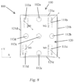
- Fig. 8 is a schematic diagram of transport of a conveyor in the positive direction of the X-axis.
- Arrow marks on the Mecanum wheels in the figure are used to indicate force application directions.
- the controller controls the Mecanum wheels 111b and 111d to rotate forward and simultaneously controls the Mecanum wheels 111a and 111c to rotate reversely, such that the Mecanum wheel 111a generates a force between the negative direction of the Y-axis and the positive direction of the X-axis; the Mecanum wheel 111b generates a force between the positive direction of the Y-axis and the positive direction of the X-axis; the Mecanum wheel 111c generates a force between the negative direction of the Y-axis and the positive direction of the X-axis; and the Mecanum wheel 111d generates a force between the positive direction of the Y-axis and the positive direction of the X-axis.
- the direction of resultant force in this case is in the positive direction of the X-axis.
- the edge stopper 121b is adjusted to the passage position, while the other three edge stoppers 121a, 121c, and 121d are maintained in the stop position.
- the battery to be replaced travels along the guide surrounded by the plurality of edge stoppers under the drive of the Mecanum wheels, and is transferred to a designated position along the positive direction of the X-axis.
- the controller controls the Mecanum wheels 111a and 111d to rotate forward and simultaneously controls the Mecanum wheels 111b and 111c to rotate reversely, such that the Mecanum wheel 111a generates a force between the positive direction of the Y-axis and the negative direction of the X-axis; the Mecanum wheel 111b generates a force between the negative direction of the Y-axis and the negative direction of the X-axis; the Mecanum wheel 111c generates a force between the negative direction of the Y-axis and the positive direction of the X-axis; and the Mecanum wheel 111d generates a force between the positive direction of the Y-axis and the positive direction of the X-axis.
- a resultant force formed by the Mecanum wheels 111a and 111d is in a positive direction along the Y-axis, while a resultant force formed by the Mecanum wheels 111b and 111c is in a negative direction along the Y-axis.
- the two together form a torque rotating clockwise, enabling the battery to be conveyed thereon to rotate clockwise.
- the edge stoppers 121a, 121b, 121c, and 121d are all adjusted to the passage positions so that the rotation process of the battery is not hindered.
Landscapes
- Engineering & Computer Science (AREA)
- Transportation (AREA)
- Structural Engineering (AREA)
- Mechanical Engineering (AREA)
- Civil Engineering (AREA)
- Life Sciences & Earth Sciences (AREA)
- Geology (AREA)
- Chemical & Material Sciences (AREA)
- Combustion & Propulsion (AREA)
- Handcart (AREA)
- Rollers For Roller Conveyors For Transfer (AREA)
- Arrangement Or Mounting Of Propulsion Units For Vehicles (AREA)
Claims (12)
- Fördereinrichtung (100), die Folgendes umfasst: einen Trägerabschnitt (120) zum Tragen einer zu befördernden Komponente; einen sich bewegenden Abschnitt (130) zum Antreiben des Trägerabschnitts (120), derart, dass er sich bewegt, dadurch gekennzeichnet, dass eine omnidirektionale Transportanordnung (110) mehrere Transportmechanismen, die auf dem Trägerabschnitt (120) angeordnet sind, wobei die Transportmechanismen jeweils zum Bereitstellen von Antriebskräften in eingestellten Richtungen verwendet werden und die zu befördernde Komponente sich in der Richtung einer resultierenden Kraft der Antriebskräfte der mehreren Transportmechanismen relativ zum Trägerabschnitt (120) bewegt; und eine Steuereinheit zum Steuern des Beginnens und Anhaltens und/oder einer Drehung vorwärts und rückwärts der mehreren Transportmechanismen, um die zu befördernde Komponente in einer eingestellten Richtung der resultierenden Kraft anzutreiben, umfasst und dass die omnidirektionale Transportanordnung (110) ferner mehrere allgemeine Räder (112a, 112b, 112c, 112d) umfasst, die jeweils nahe bei der Mitte und/oder den Rändern des Trägerabschnitts (120) angeordnet sind.
- Fördereinrichtung (100) nach Anspruch 1, dadurch gekennzeichnet, dass die Transportmechanismen Mecanum-Räder (111a, 111b, 111c, 111d) sind.
- Fördereinrichtung (100) nach Anspruch 2, dadurch gekennzeichnet, dass die Mecanum-Räder (111a, 111b, 111c, 111d) jeweils nahe bei den Rändern des Trägerabschnitts (120) angeordnet sind.
- Fördereinrichtung (100) nach Anspruch 3, dadurch gekennzeichnet, dass der Trägerabschnitt (120) in einer rechtwinkligen Form konstruiert ist und die omnidirektionale Transportanordnung (110) mindestens zwei Mecanum-Räder (111a, 111b, 111c, 111d) umfasst; wobei die zwei Mecanum-Räder (111a, 111b, 111c, 111d) jeweils in Längsrichtung oder in Querrichtung nahe bei den Rändern des Trägerabschnitts (120) angeordnet sind.
- Fördereinrichtung (100) nach Anspruch 3, dadurch gekennzeichnet, dass der Trägerabschnitt (120) in einer rechtwinkligen Form konstruiert ist und die omnidirektionale Transportanordnung (110) mindestens vier Mecanum-Räder (111a, 111b, 111c, 111d) umfasst; wobei die Mecanum-Räder (111a, 111b, 111c, 111d) jeweils in der Nähe von vier Ecken des Trägerabschnitts (120) angeordnet sind.
- Fördereinrichtung (100) nach Anspruch 1, dadurch gekennzeichnet, dass die allgemeinen Räder (112a, 112b, 112c, 112d), die in der Nähe der Ränder des Trägerabschnitts (120) angeordnet sind, jeweils zwischen zwei benachbarten Mecanum-Rädern (111a, 111b, 111c, 111d) angeordnet sind.
- Fördereinrichtung (100) nach einem der Ansprüche 1 bis 5, dadurch gekennzeichnet, dass sie ferner Randanschlagelemente (121a, 121b, 121c, 121d) umfasst, die entlang der Ränder des Trägerabschnitts (120) angeordnet sind, wobei die Randanschlagelemente (121a, 121b, 121c, 121d) konfiguriert sind, in einer jeweiligen Anhalteposition zu verhindern, dass die zu befördernde Komponente dort hindurchtritt, und in einer Durchlassposition ermöglichen, dass die zu befördernde Komponente dort hindurchtritt.
- Fördereinrichtung (100) nach Anspruch 7, dadurch gekennzeichnet, dass die Randanschlagelemente (121a, 121b, 121c, 121d) mit den Rändern des Trägerabschnitts (120) gedreht werden; dann, wenn es sich in der Anhalteposition befindet, das Randanschlagelement derart gedreht ist, dass es höher als der Trägerabschnitt (120) ist; und dann, wenn es sich in der Durchlassposition befindet, das Randanschlagelement derart gedreht ist, dass es niedriger als der Trägerabschnitt (120) ist.
- Fördereinrichtung (100) nach einem der Ansprüche 1 bis 5, dadurch gekennzeichnet, dass die Richtung der resultierenden Kraft in einer Längsrichtung oder einer Querrichtung des Trägerabschnitts (120) der Fördereinrichtung (100) verläuft.
- Fördereinrichtung (100) nach Anspruch 1, dadurch gekennzeichnet, dass der Transportmechanismus ein omnidirektionales Lenkrad ist.
- Fördereinrichtung (100) nach einem der Ansprüche 1 bis 10, dadurch gekennzeichnet, dass die Fördereinrichtung (100) zum Transportieren von auszutauschenden Batterien von Elektrofahrzeugen verwendet wird.
- Fördereinrichtung (100) nach Anspruch 11, dadurch gekennzeichnet, dass der Trägerabschnitt (120) eine Größe aufweist, die auf die Größe der auszutauschenden Batterien abgestimmt ist.
Applications Claiming Priority (2)
| Application Number | Priority Date | Filing Date | Title |
|---|---|---|---|
| CN201711035571.9A CN107757752B (zh) | 2017-10-30 | 2017-10-30 | 运输器 |
| PCT/CN2018/074165 WO2019085293A1 (zh) | 2017-10-30 | 2018-01-25 | 运输器 |
Publications (3)
| Publication Number | Publication Date |
|---|---|
| EP3705374A1 EP3705374A1 (de) | 2020-09-09 |
| EP3705374A4 EP3705374A4 (de) | 2021-09-01 |
| EP3705374B1 true EP3705374B1 (de) | 2025-06-25 |
Family
ID=61271742
Family Applications (1)
| Application Number | Title | Priority Date | Filing Date |
|---|---|---|---|
| EP18874292.8A Active EP3705374B1 (de) | 2017-10-30 | 2018-01-25 | Förderer |
Country Status (3)
| Country | Link |
|---|---|
| EP (1) | EP3705374B1 (de) |
| CN (1) | CN107757752B (de) |
| WO (1) | WO2019085293A1 (de) |
Families Citing this family (3)
| Publication number | Priority date | Publication date | Assignee | Title |
|---|---|---|---|---|
| CN111744797A (zh) * | 2019-03-27 | 2020-10-09 | 菜鸟智能物流控股有限公司 | 万向载物台及物流对象的分拨系统 |
| EP3772477A1 (de) | 2019-08-08 | 2021-02-10 | Renishaw PLC | Palettenlader für ein positionierungsgerät |
| CN110371218B (zh) * | 2019-08-22 | 2024-08-02 | 昆山市工研院智能制造技术有限公司 | 一种模块式多功能agv |
Citations (2)
| Publication number | Priority date | Publication date | Assignee | Title |
|---|---|---|---|---|
| CN105858056A (zh) * | 2016-05-27 | 2016-08-17 | 南安市晨菲雨帽业有限公司 | 一种安全性高的机动式辊道输送装置 |
| KR20170008075A (ko) * | 2015-07-13 | 2017-01-23 | 구경본 | 옴니휠을 가지는 볼어레이 이송장치 |
Family Cites Families (10)
| Publication number | Priority date | Publication date | Assignee | Title |
|---|---|---|---|---|
| DE102010050907A1 (de) * | 2010-11-11 | 2012-05-16 | Franke Gmbh | Omnidirektionales Fahrzeug zum Transportieren und Feinpositionieren von Lasten |
| CN202089587U (zh) * | 2011-06-10 | 2011-12-28 | 浚鑫科技股份有限公司 | 玻璃运输装置 |
| CN104120899B (zh) * | 2014-08-06 | 2016-08-17 | 武汉汉迪机器人科技有限公司 | 舞台全向移动座椅平台 |
| EP3034323B1 (de) * | 2014-12-16 | 2017-03-08 | Omniroll AG | Mecanumradfahrzeug sowie Betriebsverfahren |
| CN204904092U (zh) * | 2015-08-31 | 2015-12-23 | 刘建国 | 全向自动导引车 |
| JP6629567B2 (ja) * | 2015-10-27 | 2020-01-15 | 株式会社Soken | 搬送装置 |
| CN105858034A (zh) * | 2016-05-25 | 2016-08-17 | 长春理工大学 | 全方位自动运输车 |
| CN106200646A (zh) * | 2016-08-29 | 2016-12-07 | 深圳市劲拓自动化设备股份有限公司 | 一种基于全向车绕任意点定轴转动的控制方法及系统 |
| CN206086424U (zh) * | 2016-09-29 | 2017-04-12 | 深圳市劲拓自动化设备股份有限公司 | 一种基于麦克纳姆轮全向运输车的自动充电系统 |
| CN208360355U (zh) * | 2017-10-30 | 2019-01-11 | 蔚来汽车有限公司 | 运输器 |
-
2017
- 2017-10-30 CN CN201711035571.9A patent/CN107757752B/zh active Active
-
2018
- 2018-01-25 EP EP18874292.8A patent/EP3705374B1/de active Active
- 2018-01-25 WO PCT/CN2018/074165 patent/WO2019085293A1/zh not_active Ceased
Patent Citations (2)
| Publication number | Priority date | Publication date | Assignee | Title |
|---|---|---|---|---|
| KR20170008075A (ko) * | 2015-07-13 | 2017-01-23 | 구경본 | 옴니휠을 가지는 볼어레이 이송장치 |
| CN105858056A (zh) * | 2016-05-27 | 2016-08-17 | 南安市晨菲雨帽业有限公司 | 一种安全性高的机动式辊道输送装置 |
Also Published As
| Publication number | Publication date |
|---|---|
| EP3705374A1 (de) | 2020-09-09 |
| CN107757752A (zh) | 2018-03-06 |
| CN107757752B (zh) | 2020-09-22 |
| WO2019085293A1 (zh) | 2019-05-09 |
| EP3705374A4 (de) | 2021-09-01 |
Similar Documents
| Publication | Publication Date | Title |
|---|---|---|
| EP3705361B1 (de) | Batteriewechseltransportvorrichtung | |
| CN109625123B (zh) | 一种拼接式搬运车辆、搬运系统和搬运方法 | |
| CN109179264A (zh) | 一种带有可旋转式升降电动滚筒的agv搬运车 | |
| EP3705374A1 (de) | Förderer | |
| JP7601500B2 (ja) | ロールタイプ資材の自動移送供給設備 | |
| CN112389262B (zh) | 换电站以及更换动力电池的方法 | |
| WO2019085344A1 (zh) | 快速换电系统、车载电池周转方法和车载电池操作平台 | |
| JP2020117031A (ja) | 牽引車システム | |
| CN112389264A (zh) | 换电站以及更换动力电池的方法 | |
| EP4417473A1 (de) | Batterieaustauschsystem und batterieaustauschverfahren | |
| CN108749920B (zh) | 一种重型电驱动全轮转向全轮驱动无人框架运输车 | |
| JP5655700B2 (ja) | 搬送システム | |
| CN211168780U (zh) | 一种自动化装配流水线 | |
| CN118418823A (zh) | 换电方法及一体化换电设备 | |
| JP2020005403A (ja) | 電動式搬送車両の蓄電ユニット装置 | |
| CN218320604U (zh) | 一种全向搬运堆垛叉车机构 | |
| CN109878401A (zh) | 一种可变式货物搬运系统及其操作方法 | |
| CN211684749U (zh) | 换电站 | |
| CN117519213B (zh) | 一种多机器人协同货运控制方法及系统、存储介质 | |
| CN207106682U (zh) | 一种多轮驱动重载电动转运车 | |
| CN209366115U (zh) | 动力电池的运输和作业站和车辆生产流水线 | |
| CN219791327U (zh) | 用于货架轨道内牵引大重量货物的穿梭车 | |
| CN208360355U (zh) | 运输器 | |
| CN211684748U (zh) | 换电站 | |
| CN206623691U (zh) | 一种可不间断工作的agv所使用的电池系统 |
Legal Events
| Date | Code | Title | Description |
|---|---|---|---|
| STAA | Information on the status of an ep patent application or granted ep patent |
Free format text: STATUS: THE INTERNATIONAL PUBLICATION HAS BEEN MADE |
|
| PUAI | Public reference made under article 153(3) epc to a published international application that has entered the european phase |
Free format text: ORIGINAL CODE: 0009012 |
|
| STAA | Information on the status of an ep patent application or granted ep patent |
Free format text: STATUS: REQUEST FOR EXAMINATION WAS MADE |
|
| 17P | Request for examination filed |
Effective date: 20200602 |
|
| AK | Designated contracting states |
Kind code of ref document: A1 Designated state(s): AL AT BE BG CH CY CZ DE DK EE ES FI FR GB GR HR HU IE IS IT LI LT LU LV MC MK MT NL NO PL PT RO RS SE SI SK SM TR |
|
| AX | Request for extension of the european patent |
Extension state: BA ME |
|
| RAP1 | Party data changed (applicant data changed or rights of an application transferred) |
Owner name: NIO (ANHUI) HOLDING CO., LTD. |
|
| RIN1 | Information on inventor provided before grant (corrected) |
Inventor name: HAO, ZHANDUO Inventor name: CHEN, JIONG |
|
| DAV | Request for validation of the european patent (deleted) | ||
| DAX | Request for extension of the european patent (deleted) | ||
| A4 | Supplementary search report drawn up and despatched |
Effective date: 20210804 |
|
| RIC1 | Information provided on ipc code assigned before grant |
Ipc: B62D 1/02 20060101AFI20210729BHEP Ipc: B66F 9/06 20060101ALI20210729BHEP |
|
| STAA | Information on the status of an ep patent application or granted ep patent |
Free format text: STATUS: EXAMINATION IS IN PROGRESS |
|
| 17Q | First examination report despatched |
Effective date: 20240531 |
|
| REG | Reference to a national code |
Ref country code: DE Ref legal event code: R079 Free format text: PREVIOUS MAIN CLASS: B62D0001020000 Ipc: B66F0009060000 Ref country code: DE Ref legal event code: R079 Ref document number: 602018083007 Country of ref document: DE Free format text: PREVIOUS MAIN CLASS: B62D0001020000 Ipc: B66F0009060000 |
|
| GRAP | Despatch of communication of intention to grant a patent |
Free format text: ORIGINAL CODE: EPIDOSNIGR1 |
|
| STAA | Information on the status of an ep patent application or granted ep patent |
Free format text: STATUS: GRANT OF PATENT IS INTENDED |
|
| RIC1 | Information provided on ipc code assigned before grant |
Ipc: B62D 65/02 20060101ALI20250128BHEP Ipc: B62D 1/02 20060101ALI20250128BHEP Ipc: B66F 9/06 20060101AFI20250128BHEP |
|
| INTG | Intention to grant announced |
Effective date: 20250218 |
|
| GRAS | Grant fee paid |
Free format text: ORIGINAL CODE: EPIDOSNIGR3 |
|
| GRAA | (expected) grant |
Free format text: ORIGINAL CODE: 0009210 |
|
| STAA | Information on the status of an ep patent application or granted ep patent |
Free format text: STATUS: THE PATENT HAS BEEN GRANTED |
|
| AK | Designated contracting states |
Kind code of ref document: B1 Designated state(s): AL AT BE BG CH CY CZ DE DK EE ES FI FR GB GR HR HU IE IS IT LI LT LU LV MC MK MT NL NO PL PT RO RS SE SI SK SM TR |
|
| REG | Reference to a national code |
Ref country code: GB Ref legal event code: FG4D |
|
| REG | Reference to a national code |
Ref country code: CH Ref legal event code: EP |
|
| REG | Reference to a national code |
Ref country code: DE Ref legal event code: R096 Ref document number: 602018083007 Country of ref document: DE |
|
| REG | Reference to a national code |
Ref country code: CH Ref legal event code: EP |
|
| REG | Reference to a national code |
Ref country code: IE Ref legal event code: FG4D |
|
| PG25 | Lapsed in a contracting state [announced via postgrant information from national office to epo] |
Ref country code: FI Free format text: LAPSE BECAUSE OF FAILURE TO SUBMIT A TRANSLATION OF THE DESCRIPTION OR TO PAY THE FEE WITHIN THE PRESCRIBED TIME-LIMIT Effective date: 20250625 |
|
| REG | Reference to a national code |
Ref country code: LT Ref legal event code: MG9D |
|
| PG25 | Lapsed in a contracting state [announced via postgrant information from national office to epo] |
Ref country code: NO Free format text: LAPSE BECAUSE OF FAILURE TO SUBMIT A TRANSLATION OF THE DESCRIPTION OR TO PAY THE FEE WITHIN THE PRESCRIBED TIME-LIMIT Effective date: 20250925 Ref country code: GR Free format text: LAPSE BECAUSE OF FAILURE TO SUBMIT A TRANSLATION OF THE DESCRIPTION OR TO PAY THE FEE WITHIN THE PRESCRIBED TIME-LIMIT Effective date: 20250926 |
|
| PG25 | Lapsed in a contracting state [announced via postgrant information from national office to epo] |
Ref country code: BG Free format text: LAPSE BECAUSE OF FAILURE TO SUBMIT A TRANSLATION OF THE DESCRIPTION OR TO PAY THE FEE WITHIN THE PRESCRIBED TIME-LIMIT Effective date: 20250625 |
|
| PG25 | Lapsed in a contracting state [announced via postgrant information from national office to epo] |
Ref country code: HR Free format text: LAPSE BECAUSE OF FAILURE TO SUBMIT A TRANSLATION OF THE DESCRIPTION OR TO PAY THE FEE WITHIN THE PRESCRIBED TIME-LIMIT Effective date: 20250625 |
|
| PG25 | Lapsed in a contracting state [announced via postgrant information from national office to epo] |
Ref country code: RS Free format text: LAPSE BECAUSE OF FAILURE TO SUBMIT A TRANSLATION OF THE DESCRIPTION OR TO PAY THE FEE WITHIN THE PRESCRIBED TIME-LIMIT Effective date: 20250925 |
|
| PG25 | Lapsed in a contracting state [announced via postgrant information from national office to epo] |
Ref country code: LV Free format text: LAPSE BECAUSE OF FAILURE TO SUBMIT A TRANSLATION OF THE DESCRIPTION OR TO PAY THE FEE WITHIN THE PRESCRIBED TIME-LIMIT Effective date: 20250625 |
|
| REG | Reference to a national code |
Ref country code: NL Ref legal event code: MP Effective date: 20250625 |
|
| PG25 | Lapsed in a contracting state [announced via postgrant information from national office to epo] |
Ref country code: NL Free format text: LAPSE BECAUSE OF FAILURE TO SUBMIT A TRANSLATION OF THE DESCRIPTION OR TO PAY THE FEE WITHIN THE PRESCRIBED TIME-LIMIT Effective date: 20250625 |
|
| PG25 | Lapsed in a contracting state [announced via postgrant information from national office to epo] |
Ref country code: PT Free format text: LAPSE BECAUSE OF FAILURE TO SUBMIT A TRANSLATION OF THE DESCRIPTION OR TO PAY THE FEE WITHIN THE PRESCRIBED TIME-LIMIT Effective date: 20251027 |
|
| REG | Reference to a national code |
Ref country code: AT Ref legal event code: MK05 Ref document number: 1806314 Country of ref document: AT Kind code of ref document: T Effective date: 20250625 |
|
| PG25 | Lapsed in a contracting state [announced via postgrant information from national office to epo] |
Ref country code: IS Free format text: LAPSE BECAUSE OF FAILURE TO SUBMIT A TRANSLATION OF THE DESCRIPTION OR TO PAY THE FEE WITHIN THE PRESCRIBED TIME-LIMIT Effective date: 20251025 |
|
| PG25 | Lapsed in a contracting state [announced via postgrant information from national office to epo] |
Ref country code: AT Free format text: LAPSE BECAUSE OF FAILURE TO SUBMIT A TRANSLATION OF THE DESCRIPTION OR TO PAY THE FEE WITHIN THE PRESCRIBED TIME-LIMIT Effective date: 20250625 Ref country code: SM Free format text: LAPSE BECAUSE OF FAILURE TO SUBMIT A TRANSLATION OF THE DESCRIPTION OR TO PAY THE FEE WITHIN THE PRESCRIBED TIME-LIMIT Effective date: 20250625 |
|
| PG25 | Lapsed in a contracting state [announced via postgrant information from national office to epo] |
Ref country code: CZ Free format text: LAPSE BECAUSE OF FAILURE TO SUBMIT A TRANSLATION OF THE DESCRIPTION OR TO PAY THE FEE WITHIN THE PRESCRIBED TIME-LIMIT Effective date: 20250625 |
|
| PG25 | Lapsed in a contracting state [announced via postgrant information from national office to epo] |
Ref country code: PL Free format text: LAPSE BECAUSE OF FAILURE TO SUBMIT A TRANSLATION OF THE DESCRIPTION OR TO PAY THE FEE WITHIN THE PRESCRIBED TIME-LIMIT Effective date: 20250625 |
|
| PG25 | Lapsed in a contracting state [announced via postgrant information from national office to epo] |
Ref country code: EE Free format text: LAPSE BECAUSE OF FAILURE TO SUBMIT A TRANSLATION OF THE DESCRIPTION OR TO PAY THE FEE WITHIN THE PRESCRIBED TIME-LIMIT Effective date: 20250625 |
|
| PG25 | Lapsed in a contracting state [announced via postgrant information from national office to epo] |
Ref country code: SK Free format text: LAPSE BECAUSE OF FAILURE TO SUBMIT A TRANSLATION OF THE DESCRIPTION OR TO PAY THE FEE WITHIN THE PRESCRIBED TIME-LIMIT Effective date: 20250625 |
|
| PG25 | Lapsed in a contracting state [announced via postgrant information from national office to epo] |
Ref country code: ES Free format text: LAPSE BECAUSE OF FAILURE TO SUBMIT A TRANSLATION OF THE DESCRIPTION OR TO PAY THE FEE WITHIN THE PRESCRIBED TIME-LIMIT Effective date: 20250625 |
|
| REG | Reference to a national code |
Ref country code: DE Ref legal event code: R097 Ref document number: 602018083007 Country of ref document: DE |
|
| PGFP | Annual fee paid to national office [announced via postgrant information from national office to epo] |
Ref country code: GB Payment date: 20260123 Year of fee payment: 9 |
|
| PG25 | Lapsed in a contracting state [announced via postgrant information from national office to epo] |
Ref country code: DK Free format text: LAPSE BECAUSE OF FAILURE TO SUBMIT A TRANSLATION OF THE DESCRIPTION OR TO PAY THE FEE WITHIN THE PRESCRIBED TIME-LIMIT Effective date: 20250625 |
|
| PGFP | Annual fee paid to national office [announced via postgrant information from national office to epo] |
Ref country code: DE Payment date: 20260121 Year of fee payment: 9 |
|
| PG25 | Lapsed in a contracting state [announced via postgrant information from national office to epo] |
Ref country code: IT Free format text: LAPSE BECAUSE OF FAILURE TO SUBMIT A TRANSLATION OF THE DESCRIPTION OR TO PAY THE FEE WITHIN THE PRESCRIBED TIME-LIMIT Effective date: 20250625 |
|
| PGFP | Annual fee paid to national office [announced via postgrant information from national office to epo] |
Ref country code: FR Payment date: 20260123 Year of fee payment: 9 |
|
| PLBE | No opposition filed within time limit |
Free format text: ORIGINAL CODE: 0009261 |
|
| STAA | Information on the status of an ep patent application or granted ep patent |
Free format text: STATUS: NO OPPOSITION FILED WITHIN TIME LIMIT |
|
| REG | Reference to a national code |
Ref country code: CH Ref legal event code: L10 Free format text: ST27 STATUS EVENT CODE: U-0-0-L10-L00 (AS PROVIDED BY THE NATIONAL OFFICE) Effective date: 20260507 |
|
| 26N | No opposition filed |
Effective date: 20260326 |
|
| PG25 | Lapsed in a contracting state [announced via postgrant information from national office to epo] |
Ref country code: LT Free format text: LAPSE BECAUSE OF FAILURE TO SUBMIT A TRANSLATION OF THE DESCRIPTION OR TO PAY THE FEE WITHIN THE PRESCRIBED TIME-LIMIT Effective date: 20250625 |
|
| PG25 | Lapsed in a contracting state [announced via postgrant information from national office to epo] |
Ref country code: SE Free format text: LAPSE BECAUSE OF FAILURE TO SUBMIT A TRANSLATION OF THE DESCRIPTION OR TO PAY THE FEE WITHIN THE PRESCRIBED TIME-LIMIT Effective date: 20250625 |