EP3705364B1 - Stabilisator eines fahrzeugs - Google Patents
Stabilisator eines fahrzeugs Download PDFInfo
- Publication number
- EP3705364B1 EP3705364B1 EP20159950.3A EP20159950A EP3705364B1 EP 3705364 B1 EP3705364 B1 EP 3705364B1 EP 20159950 A EP20159950 A EP 20159950A EP 3705364 B1 EP3705364 B1 EP 3705364B1
- Authority
- EP
- European Patent Office
- Prior art keywords
- vehicle
- electro
- hydraulic
- cylinder
- hydraulic unit
- Prior art date
- Legal status (The legal status is an assumption and is not a legal conclusion. Google has not performed a legal analysis and makes no representation as to the accuracy of the status listed.)
- Not-in-force
Links
Images






Classifications
-
- B—PERFORMING OPERATIONS; TRANSPORTING
- B60—VEHICLES IN GENERAL
- B60S—SERVICING, CLEANING, REPAIRING, SUPPORTING, LIFTING, OR MANOEUVRING OF VEHICLES, NOT OTHERWISE PROVIDED FOR
- B60S9/00—Ground-engaging vehicle fittings for supporting, lifting, or manoeuvring the vehicle, wholly or in part, e.g. built-in jacks
- B60S9/02—Ground-engaging vehicle fittings for supporting, lifting, or manoeuvring the vehicle, wholly or in part, e.g. built-in jacks for only lifting or supporting
- B60S9/10—Ground-engaging vehicle fittings for supporting, lifting, or manoeuvring the vehicle, wholly or in part, e.g. built-in jacks for only lifting or supporting by fluid pressure
- B60S9/12—Ground-engaging vehicle fittings for supporting, lifting, or manoeuvring the vehicle, wholly or in part, e.g. built-in jacks for only lifting or supporting by fluid pressure of telescopic type
Definitions
- the present description relates generally to motor vehicles and, more particularly, to motor homes or motor homes.
- One embodiment overcomes all or part of the drawbacks of known systems.
- the device further comprises at least one intermediate piece for fixing the electro-hydraulic unit to a structural element of a vehicle.
- the intermediate piece or pieces are shaped as a function of the vehicle model intended to receive the electrohydraulic units.
- each jack comprises an adjustment foot prior to a maneuver of the jack, adapted to increase a stroke of the jack, preferably over a range of 50 mm, this foot then remaining fixed during the maneuver of the jack.
- moving parts, adjustment elements and hydraulic compartments, associated with electro-hydraulic units are coated with an anti-corrosion substance.
- One embodiment provides for a vehicle stabilizer system, comprising four devices as described.
- the electrohydraulic units are suitable for effecting a modification of the attitude of a vehicle, when stationary, relative to a bearing surface.
- an electronic circuit is adapted to individually control each electrohydraulic unit.
- the electronic circuit comprises elements for protection against external electromagnetic disturbances.
- the electronic circuit comprises a gyroscopic device adapted to automatically adjust the attitude of the vehicle relative to a bearing surface having a slope not exceeding 10%, preferably 6%.
- One embodiment provides for a system comprising a man-machine interface connected to the electronic circuit via a wired link.
- One embodiment provides for a system comprising a man-machine interface connected to the electronic circuit via a wireless link.
- One embodiment provides a system suitable for lifting a vehicle with a weight not exceeding 3.5 t.
- the figure 1 schematically shows a vehicle equipped with an embodiment of a vehicle stabilizer system.
- the electro-hydraulic units 3 modify an attitude of the stationary vehicle with respect to a bearing surface 5 (typically, a ground) located under this vehicle.
- the four electro-hydraulic units 3 are connected, preferably connected, to a control unit 71.
- the control unit 71 controls the respective movements of the electro-hydraulic units 3 during a stabilization operation of the vehicle 1.
- a man-machine interface 9 or remote control is furthermore connected, preferably connected, to the control unit 71.
- the remote control 9 is adapted to control the vehicle stabilizer system.
- the remote control 9 is preferably installed near a driving position of the vehicle 1.
- the control unit 71 is connected to a source 17 of electrical power, preferably a battery on board the vehicle 1.
- the figure 2 is a perspective view of one embodiment of a vehicle stabilizer device.
- the mounting part 21 is dimensioned as a function of a desired thrust force, developed by the electro-hydraulic unit 3, during a stabilization operation.
- a removable mechanical assembly 23 (for example, consisting of clips and clips) connects the mounting part 21 to the vehicle 1.
- the electro-hydraulic unit 3 is thus easily removable for maintenance and / or maintenance purposes. or repair and / or migration to another vehicle of all or part of a stabilization system.
- the electro-hydraulic unit 3 comprises a single-acting cylinder 33.
- a lower end of this jack 33 comprises a sole 35 of cylindrical shape.
- the sole 35 is adapted to establish a plane support with a surface 5 facing one another.
- the sole 35 is connected to the mounting part by at least one return spring 37, preferably by two return springs. This or these return springs 37 are adapted to return the cylinder 33 to a retracted position.
- a multi-conductor cable carries electrical signals intended to supply the electro-hydraulic unit 3.
- This cable is preferably protected by a sheath 39, typically a flexible corrugated tube or a trough.
- the sheath 39 constitutes a protective barrier for the cable against possible external attacks (for example, water splashes or shocks).
- a waterproof connector (not shown) connects the multi-conductor cable to the body 31 of the electrohydraulic unit 3 protected by a casing 317.
- the jack 33 is irreversible by construction. In other words, no electric power source is required to maintain a position taken by the jack 33 at the end of the stabilization operation.
- the figure 3 is a view, partially in section, of an embodiment of a vehicle stabilizer device.
- the electro-hydraulic unit 3 comprises a limit switch 32 (typically, a position switch).
- the sensor 32 consists of a metal tube mounted parallel to the body of the jack.
- the tube comprises at a lower end, close to the sole 35, a movable pusher-type element 322.
- the sensor 32 is arranged or adjusted in height so that, when the jack 33 is brought back to the retracted position, the sole 35 comes to actuate the pusher 322.
- the pusher 322 is mechanically linked to an electrical switch (typically, a potential-free contact). Each actuation or release of the push-button 322 thus causes a switching of the switch.
- the security of the system is thus reinforced compared to a configuration where a cut in the wire of the sensor 32 could be confused with a detection of the retracted position of the jack 33 (for example, by using a normally closed contact).
- the electro-hydraulic unit 3 comprises two return springs 37.
- these springs 37 exert a tensile force on the sole 35.
- the two return springs 37 are attached to either side of the part. 21 insert of device 2 comprising unit 3.
- the intermediate piece 21 is kept integral with the structural element 15 of the vehicle by means of two clips 23.
- These clips 23 each comprise threaded rods 25 on which the intermediate piece 21 is bolted.
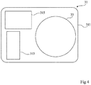
- the figure 4 schematically and partially shows an embodiment of a body of an electro-hydraulic unit of a vehicle stabilizer device.
- the electric motor 313 is associated with a pump body (not shown), the assembly thus forming a motor pump.
- This motor pump is adapted to pressurize the hydraulic liquid, contained in the hydraulic bag 315, for actuating the cylinder 33.
- the elements 33, 313, 315 are protected against possible external attacks (splashing water, dust, shocks, etc.) by the protective casing 317.
- moving parts of the single-acting cylinder 33 as well as an external surface of the hydraulic pocket 315 are coated with an anti-corrosion substance (typically, grease).
- the figure 5 represents schematically and partially, by views (A) and (B), of the modes of realization of an electro-hydraulic unit of a vehicle stabilizer device in the deployed position.
- a single-acting cylinder 33 is integral with a body 31 of the electrohydraulic unit 3.
- This cylinder 33 is in particular made up of several concentric cylinders. Relative movements of these cylinders along the same axis result in a modification of the total length of the jack 33.
- the jack 33 At a lower end, the jack 33 comprises a foot 331 on which is fixed a sole 35. A part of the foot is preferably threaded.
- the foot 331 makes it possible to adjust, by screwing or unscrewing, a distance between the lower end of the last cylinder of the jack 33 and the sole 35. A possibility of presetting, preferably over a range of 50 mm, is thus offered. before a stabilization operation of a vehicle. In other words, the foot 331 acts as an adjustable extension prior to the stabilization operation.
- the height of the foot 331 is adjusted once and for all for a given vehicle.
- the view (A) of the figure 5 shows the foot 331 in an unscrewed position while the view (B) shows the foot 331 in a screwed position.
- a feature associated with this foot consists of modifying the length of the cylinder rod before deployment.
- the figure 6 schematically and partially shows, by views (A) and (B), embodiments of an electro-hydraulic unit of a vehicle stabilizer device in the retracted position.
- View (A) shows foot 331 in an unscrewed position while view (B) shows foot 331 in a screwed position.
- the figure 7 shows another embodiment of a vehicle stabilizer device.
- the single-acting cylinder 33 of the electro-hydraulic unit 3 is arranged such that the single-acting cylinder is perpendicular to the upper plate 311.
- On this plate 311 is fixed the part 21 for adaptation to the chassis of vehicle.
- the protective casing 317 envelops the elements associated with the jack 33 (for example, the motor pump 313 pressurizing a liquid for actuating the jack 33 contained in the reservoir 315).
- the limit switch 32 is placed opposite the sole 35.
- the sole 35 is secured to the jack by means of the foot 331 (for example, a threaded rod comprising a cylindrical head nested in the sole).
- the external power source 45 is a battery on board the vehicle 1.
- the man-machine interface 4 facilitates maintenance and repair operations by offering the possibility of controlling the electro-hydraulic unit 3 independently of the control unit 71.
- the figure 8 is a top view of an embodiment of a sole of an electro-hydraulic unit.
- the sole 35 consists of a one-piece structure 351 and a puck 353 or damper pad.
- the structure of a hollow cylindrical shape, has radial ribs. These radial ribs help to stiffen the structure of the sole 35. They thus make it possible to avoid any plastic deformation (irreversible) or rupture of the structure during a stabilization operation.
- two electro-hydraulic units 3 installed at the front of a vehicle 1 comprise soles 35 made of a mixture of polymer materials reinforced with glass fibers. This improves the strength of the soles 35 which support the most important weight of the vehicle 1 (engine side).
- the damper puck 353 is in turn made of a flexible material (eg rubber). This puck is suitable for absorbing vibrations or shocks liable to propagate between an electrohydraulic unit 3 and a bearing surface 5.
- the damping puck 353 also contributes to limiting transient mechanical stresses exerted on the level. of the electrohydraulic unit 3. This limitation of the mechanical stresses is intended to increase the service life of the system and to improve the comfort felt by the occupants of the vehicle 1.
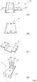
- the figure 9 shows, by views (A), (B), (C) and (D), embodiments of mounting parts of electrohydraulic units.
- an interface piece 21, or an intermediate piece is conformed to a type of vehicle.
- This intermediate piece 21 is involved in a mechanical assembly, preferably removable, suitable for fixing an electrohydraulic unit 3 on a structural element 15 of a vehicle.
- the intermediate piece 21 comprises a first piece 211 fixed (for example, added welded) to a second piece 213.
- the first piece 211 has a square shape shaped as a function of a specific vehicle chassis.
- the second part 213 consists of a sheet having a profile in the form of an inverted omega. This second part is adapted to receive an electrohydraulic unit 3.
- the second part 213 is typically obtained by folding.
- the intermediate piece 21 consists of a sheet having an “L” -shaped profile. This part is typically obtained by folding.
- the intermediate piece 21 consists of a sheet having a profile in the form of an inverted omega. This part is typically obtained by folding.
- the intermediate piece 21 consists of a sheet 215 having a U-shaped profile.
- the sheet 215 has four threaded holes, each accommodating a threaded rod 217.
- the profile of the sheet 215 is typically obtained by bending.
- the spacers 21 have bores and / or bores and / or threads. These machining operations give the interface part 21 structural characteristics suitable for establishing a connection between the electro-hydraulic unit 3 and the chassis element 15 of the vehicle.
- the figure 10 schematically shows an embodiment of a control unit of a vehicle stabilizer system.
- a control unit 71 comprises an electronic circuit 711 placed inside a housing 713.
- the housing 713 protects the circuit 711 against possible external attacks (splashing water, dust, shocks, etc.).
- Circuit 711 is connected, preferably connected, to a power source 17 (POWER SOURCE).
- POWER SOURCE a power source 17
- the circuit 711 is supplied at a voltage of approximately 12 volts by connection to two terminals of a battery on board a vehicle.
- the circuit 711 is supplied at a voltage of approximately 12 volts obtained at the output of a power converter (for example, a switching power supply connected at the input to a single-phase AC source 230 volts, 50 Hz ).
- the circuit 711 comprises a gyroscopic device 719 adapted to automatically adjust the attitude of a vehicle with respect to a bearing surface.
- the bearing surface has a slope not exceeding 10%, preferably 6%.
- the circuit 711 further comprises elements for protection against external electromagnetic disturbances.
- the remote control 9 dialogues with the circuit 711 via a wireless connection.
- the figure 11 schematically shows an embodiment of a man-machine interface suitable for controlling a vehicle stabilizer system.
- a conventional man-machine interface 9 (for example, a button box), or remote control, is suitable for controlling the vehicle stabilizer system.
- This remote control 9 comprises a perforated housing 91 accommodating actuators and indicator lights.
- the remote control 9 comprises only part of the above elements.
- the remote control 9 is connected, preferably connected, to the electronic circuit of a control unit by means of a multiconductor cable 93.
- Cable 93 carries control signals from the pushbuttons and switches of the remote control 9 to the electronic circuit (not shown in figure 11 ).
- the cable 93 further carries signaling signals from the electronic circuit to the remote control.
- the figure 12 shows one embodiment of a state diagram of a vehicle stabilizer system.
- pressing the switch 911 causes a power-on (PWR ON) of the electronic circuit 711 ( figure 10 ).
- Circuit 711 then enters an internal adjustment phase (INT CONFIG). For example, LED 916 ( figure 11 ) flashes at the end of this internal adjustment phase.
- Circuit 711 then goes into a standby mode (WAIT MODE). In this standby mode, the circuit 711 updates, if necessary, internal information (for example, states of the sensors) while awaiting a command from a user.
Landscapes
- Physics & Mathematics (AREA)
- Fluid Mechanics (AREA)
- Engineering & Computer Science (AREA)
- Mechanical Engineering (AREA)
- Vehicle Body Suspensions (AREA)
Claims (15)
- Fahrzeugstabilisierungsvorrichtung (2), die eine elektrohydraulische Einheit (3) umfasst, die Folgendes aufweist:einen einfach-wirkenden Zylinder (33);mindestens eine Feder (37) zur Rückstellung in Richtung einer eingefahrenen Position des Zylinders (33);eine Grundplatte (35), die geeignet ist, einen Kontakt zwischen einem Ende des Zylinders (33) und einer Auflagefläche (5) herzustellendadurch gekennzeichnet, dass die Grundplatte Folgendes aufweist:eine Hohlstruktur (351) mit radialen Rippen, die aus einer Mischung von Polymermaterialien und Glasfasern hergestellt ist; undeinen stoßdämpfenden Puffer (353), der aus einem flexiblen Material, vorzugsweise aus Gummi, hergestellt ist.
- Vorrichtung nach Anspruch 1, die mindestens ein Zwischenstück (21) zur Befestigung der elektrohydraulischen Einheit (3) an einem Bauteil (15) eines Fahrzeugs (1) aufweist.
- Vorrichtung nach Anspruch 2, wobei das oder die Zwischenstücke (21) entsprechend dem zur Aufnahme der elektrohydraulischen Einheit (3) vorgesehenen Fahrzeugmodell geformt sind.
- Vorrichtung nach einem der Ansprüche 1 bis 3, wobei der Zylinder (33) einen Verstellfuß (331) aufweist, der geeignet ist, vor einem Betrieb des Zylinders (33) einen Hub des Zylinders (33), vorzugsweise über einen Bereich von 50 mm, zu vergrößern, wobei dieser Fuß (331) dann während des Betriebs des Zylinders (33) fixiert bleibt.
- Vorrichtung nach einem der Ansprüche 1 bis 4, wobei die elektrohydraulische Einheit (3) Folgendes aufweist:einen flexiblen Vorratsbehälter (315), der eine Hydraulikflüssigkeit zur Betätigung des Zylinders (33) enthält; undeine Elektromotorpumpe (313), die geeignet ist, die in dem flexiblen Reservoir (315) enthaltene Hydraulikflüssigkeit unter Druck zu setzen.
- Vorrichtung nach einem der Ansprüche 1 bis 5, wobei bewegliche Teile (33), Verstellelemente (331) und Hydraulikräume (315), die der elektrohydraulischen Einheit (3) zugeordnet sind, mit einer antikorrosiven Substanz beschichtet sind.
- Fahrzeugstabilisierungssystem, das vier Vorrichtungen (2) nach einem der Ansprüche 1 bis 6 aufweist.
- System nach Anspruch 7, wobei die elektro-hydraulischen Einheiten (3) geeignet sind, eine Änderung der Lage eines stehenden Fahrzeugs (1) relativ zu einer Auflagefläche (5) durchzuführen.
- System nach Anspruch 7 oder 8, wobei eine elektronische Schaltung (711) dazu eingerichtet ist, jede elektrohydraulische Einheit (3) einzeln anzusteuern.
- System nach Anspruch 9, wobei die elektronische Schaltung (711) Elemente zum Schutz gegen externe elektromagnetische Störungen aufweist.
- System nach Anspruch 9 oder 10, wobei die elektronische Schaltung (711) eine gyroskopische Vorrichtung (719) aufweist, die geeignet ist, die Lage des Fahrzeugs (1) relativ zu einer Auflagefläche (5) mit einer Neigung, die 10 %, vorzugsweise 6 %, nicht überschreitet, automatisch einzustellen.
- System nach einem der Ansprüche 9 bis 11, das eine Mensch-Maschine-Schnittstelle (9) aufweist, die über eine Drahtverbindung (93) mit der elektronischen Schaltung (711) gekoppelt ist.
- System nach einem der Ansprüche 9 bis 11, das eine Mensch-Maschine-Schnittstelle (9) aufweist, die über eine drahtlose Verbindung mit der elektronischen Schaltung (711) gekoppelt ist.
- System nach einem der Ansprüche 9 bis 13, die eine Mensch-Maschine-Schnittstelle (4) aufweist, die direkt verbindbar ist:mit einer einzelnen der elektrohydraulischen Einheiten (3) über einen Verbinder (43); undmit einer externen Leistungsversorgung (45),wobei diese Mensch-Maschine-Schnittstelle (4) geeignet ist, die betreffende elektrohydraulische Einheit (3) unabhängig vom Zustand der elektronischen Schaltung (711) zu steuern.
- System nach einem der Ansprüche 9 bis 14, das geeignet ist zum Anheben eines Fahrzeugs (1) mit einem Gewicht, das 3,5 t nicht übersteigt.
Applications Claiming Priority (1)
| Application Number | Priority Date | Filing Date | Title |
|---|---|---|---|
| FR1902381A FR3093486A1 (fr) | 2019-03-08 | 2019-03-08 | Stabilisateur de véhicule |
Publications (2)
| Publication Number | Publication Date |
|---|---|
| EP3705364A1 EP3705364A1 (de) | 2020-09-09 |
| EP3705364B1 true EP3705364B1 (de) | 2021-03-24 |
Family
ID=67742566
Family Applications (1)
| Application Number | Title | Priority Date | Filing Date |
|---|---|---|---|
| EP20159950.3A Not-in-force EP3705364B1 (de) | 2019-03-08 | 2020-02-28 | Stabilisator eines fahrzeugs |
Country Status (4)
| Country | Link |
|---|---|
| EP (1) | EP3705364B1 (de) |
| ES (1) | ES2877068T3 (de) |
| FR (1) | FR3093486A1 (de) |
| PT (1) | PT3705364T (de) |
Families Citing this family (1)
| Publication number | Priority date | Publication date | Assignee | Title |
|---|---|---|---|---|
| FR3119591A1 (fr) * | 2021-02-05 | 2022-08-12 | Cal4Uze | Stabilisateur de véhicule |
Family Cites Families (6)
| Publication number | Priority date | Publication date | Assignee | Title |
|---|---|---|---|---|
| US3214137A (en) * | 1963-12-04 | 1965-10-26 | Darwin A Reichert | Landing gear for semi-trailers |
| US4165861A (en) * | 1978-02-01 | 1979-08-28 | Hwh Corporation | Vehicle leveling system |
| US5419524A (en) * | 1993-03-12 | 1995-05-30 | Evans; Leonard W. | Weight distribution pad for trailers |
| US5628521A (en) * | 1993-07-26 | 1997-05-13 | Versa Technologies, Inc. | Manually operated vehicle leveling system |
| US5527054A (en) * | 1995-07-03 | 1996-06-18 | Williams; A. Wayne | Leg adjustment for fifth-wheel trailer lifting/leveling legs |
| US10427654B2 (en) * | 2016-07-19 | 2019-10-01 | Norco Industries, Inc. | Three point vehicle leveling with multi point stabilizing systems |
-
2019
- 2019-03-08 FR FR1902381A patent/FR3093486A1/fr not_active Withdrawn
-
2020
- 2020-02-28 EP EP20159950.3A patent/EP3705364B1/de not_active Not-in-force
- 2020-02-28 ES ES20159950T patent/ES2877068T3/es active Active
- 2020-02-28 PT PT201599503T patent/PT3705364T/pt unknown
Also Published As
| Publication number | Publication date |
|---|---|
| EP3705364A1 (de) | 2020-09-09 |
| PT3705364T (pt) | 2021-06-24 |
| ES2877068T3 (es) | 2021-11-16 |
| FR3093486A1 (fr) | 2020-09-11 |
Similar Documents
| Publication | Publication Date | Title |
|---|---|---|
| FR2540799A1 (fr) | Dispositif de propulsion pour echafaudages de travail | |
| FR2927026A1 (fr) | Poste de pilotage d'un vehicule | |
| FR2554415A1 (fr) | Atterrisseurs pour aeronef, notamment pour helicoptere | |
| EP3705364B1 (de) | Stabilisator eines fahrzeugs | |
| CA2606557C (fr) | Dispositif d'elinguage d'une piece avec compensation d'effort et systeme de levage le comprenant | |
| FR3013680A3 (fr) | Train d'atterrissage pour un avion leger ou un aeronef sans equipage et aeronef equipe d'un tel train d'atterrissage | |
| FR3008404A1 (fr) | Plateforme de nacelle elevatrice et nacelle elevatrice equipee d'une telle plateforme | |
| EP3335957A1 (de) | Schwenktür mit integrierter erhöhter schwelle | |
| EP3127746B1 (de) | Beleuchtungs- und/oder signalisierungsvorrichtung eines kraftfahrzeugs, die mindestens zwei leuchtmodule umfassen | |
| EP0905083B1 (de) | Wagen mit Hubmast, geeignet zur Montage an das Ende eines Transportfahrzeugs | |
| FR2771368A1 (fr) | Bequille hydraulique pour moto | |
| EP3885307A1 (de) | Stabilisierungsvorrichtung für einen vertikallift für eine person | |
| EP0378949A1 (de) | In der Höhe verriegelbare pneumatische Aufhängung für Industriefahrzeuge | |
| FR2597801A1 (fr) | Vehicule a systeme de suspension reglable pour faciliter l'acces a un fauteuil roulant | |
| EP0208572B1 (de) | Automatischer Rollenstabilisator | |
| FR2503055A1 (fr) | Suspension pour vehicule | |
| EP2910513A1 (de) | Hebevorrichtung mit einer Regulierung der Höhenlage | |
| EP2353991A2 (de) | Tragfluegelboot | |
| FR2585668A1 (fr) | Perfectionnements apportes aux engins volants du type a voilure parachute | |
| FR2904286A1 (fr) | Chariot elevateur guide par timon avec fonction de conduite tres lente. | |
| FR3119591A1 (fr) | Stabilisateur de véhicule | |
| FR2504905A1 (fr) | Chariot de manutention comportant un dispositif de suspension entre son chassis et son ensemble elevateur | |
| CH405662A (fr) | Elévateur à nacelle | |
| EP1967668A2 (de) | Über Translationsbewegung öffnende Rauchabzugsanlage | |
| EP4353580A1 (de) | Plattform zum heben und heben von bootsanschlägen mit einem drehbaren und verschiebbaren hebe- und aushebe-gateway |
Legal Events
| Date | Code | Title | Description |
|---|---|---|---|
| PUAI | Public reference made under article 153(3) epc to a published international application that has entered the european phase |
Free format text: ORIGINAL CODE: 0009012 |
|
| STAA | Information on the status of an ep patent application or granted ep patent |
Free format text: STATUS: THE APPLICATION HAS BEEN PUBLISHED |
|
| AK | Designated contracting states |
Kind code of ref document: A1 Designated state(s): AL AT BE BG CH CY CZ DE DK EE ES FI FR GB GR HR HU IE IS IT LI LT LU LV MC MK MT NL NO PL PT RO RS SE SI SK SM TR |
|
| AX | Request for extension of the european patent |
Extension state: BA ME |
|
| STAA | Information on the status of an ep patent application or granted ep patent |
Free format text: STATUS: REQUEST FOR EXAMINATION WAS MADE |
|
| 17P | Request for examination filed |
Effective date: 20200923 |
|
| RBV | Designated contracting states (corrected) |
Designated state(s): AL AT BE BG CH CY CZ DE DK EE ES FI FR GB GR HR HU IE IS IT LI LT LU LV MC MK MT NL NO PL PT RO RS SE SI SK SM TR |
|
| GRAP | Despatch of communication of intention to grant a patent |
Free format text: ORIGINAL CODE: EPIDOSNIGR1 |
|
| STAA | Information on the status of an ep patent application or granted ep patent |
Free format text: STATUS: GRANT OF PATENT IS INTENDED |
|
| RIC1 | Information provided on ipc code assigned before grant |
Ipc: B60S 9/12 20060101AFI20201202BHEP |
|
| INTG | Intention to grant announced |
Effective date: 20201222 |
|
| GRAS | Grant fee paid |
Free format text: ORIGINAL CODE: EPIDOSNIGR3 |
|
| GRAA | (expected) grant |
Free format text: ORIGINAL CODE: 0009210 |
|
| STAA | Information on the status of an ep patent application or granted ep patent |
Free format text: STATUS: THE PATENT HAS BEEN GRANTED |
|
| AK | Designated contracting states |
Kind code of ref document: B1 Designated state(s): AL AT BE BG CH CY CZ DE DK EE ES FI FR GB GR HR HU IE IS IT LI LT LU LV MC MK MT NL NO PL PT RO RS SE SI SK SM TR |
|
| REG | Reference to a national code |
Ref country code: GB Ref legal event code: FG4D Free format text: NOT ENGLISH |
|
| REG | Reference to a national code |
Ref country code: CH Ref legal event code: EP |
|
| REG | Reference to a national code |
Ref country code: IE Ref legal event code: FG4D Free format text: LANGUAGE OF EP DOCUMENT: FRENCH |
|
| REG | Reference to a national code |
Ref country code: DE Ref legal event code: R096 Ref document number: 602020000037 Country of ref document: DE Ref country code: AT Ref legal event code: REF Ref document number: 1374182 Country of ref document: AT Kind code of ref document: T Effective date: 20210415 |
|
| REG | Reference to a national code |
Ref country code: PT Ref legal event code: SC4A Ref document number: 3705364 Country of ref document: PT Date of ref document: 20210624 Kind code of ref document: T Free format text: AVAILABILITY OF NATIONAL TRANSLATION Effective date: 20210617 |
|
| REG | Reference to a national code |
Ref country code: DE Ref legal event code: R081 Ref document number: 602020000037 Country of ref document: DE Owner name: CAL4UZE, FR Free format text: FORMER OWNER: CAL4UZE, SEYSSINET-PARISET, FR |
|
| RAP4 | Party data changed (patent owner data changed or rights of a patent transferred) |
Owner name: CAL4UZE |
|
| REG | Reference to a national code |
Ref country code: LT Ref legal event code: MG9D |
|
| PG25 | Lapsed in a contracting state [announced via postgrant information from national office to epo] |
Ref country code: NO Free format text: LAPSE BECAUSE OF FAILURE TO SUBMIT A TRANSLATION OF THE DESCRIPTION OR TO PAY THE FEE WITHIN THE PRESCRIBED TIME-LIMIT Effective date: 20210624 Ref country code: FI Free format text: LAPSE BECAUSE OF FAILURE TO SUBMIT A TRANSLATION OF THE DESCRIPTION OR TO PAY THE FEE WITHIN THE PRESCRIBED TIME-LIMIT Effective date: 20210324 Ref country code: GR Free format text: LAPSE BECAUSE OF FAILURE TO SUBMIT A TRANSLATION OF THE DESCRIPTION OR TO PAY THE FEE WITHIN THE PRESCRIBED TIME-LIMIT Effective date: 20210625 Ref country code: HR Free format text: LAPSE BECAUSE OF FAILURE TO SUBMIT A TRANSLATION OF THE DESCRIPTION OR TO PAY THE FEE WITHIN THE PRESCRIBED TIME-LIMIT Effective date: 20210324 Ref country code: BG Free format text: LAPSE BECAUSE OF FAILURE TO SUBMIT A TRANSLATION OF THE DESCRIPTION OR TO PAY THE FEE WITHIN THE PRESCRIBED TIME-LIMIT Effective date: 20210624 |
|
| PG25 | Lapsed in a contracting state [announced via postgrant information from national office to epo] |
Ref country code: LV Free format text: LAPSE BECAUSE OF FAILURE TO SUBMIT A TRANSLATION OF THE DESCRIPTION OR TO PAY THE FEE WITHIN THE PRESCRIBED TIME-LIMIT Effective date: 20210324 Ref country code: SE Free format text: LAPSE BECAUSE OF FAILURE TO SUBMIT A TRANSLATION OF THE DESCRIPTION OR TO PAY THE FEE WITHIN THE PRESCRIBED TIME-LIMIT Effective date: 20210324 Ref country code: RS Free format text: LAPSE BECAUSE OF FAILURE TO SUBMIT A TRANSLATION OF THE DESCRIPTION OR TO PAY THE FEE WITHIN THE PRESCRIBED TIME-LIMIT Effective date: 20210324 |
|
| REG | Reference to a national code |
Ref country code: NL Ref legal event code: MP Effective date: 20210324 |
|
| REG | Reference to a national code |
Ref country code: AT Ref legal event code: MK05 Ref document number: 1374182 Country of ref document: AT Kind code of ref document: T Effective date: 20210324 |
|
| PG25 | Lapsed in a contracting state [announced via postgrant information from national office to epo] |
Ref country code: NL Free format text: LAPSE BECAUSE OF FAILURE TO SUBMIT A TRANSLATION OF THE DESCRIPTION OR TO PAY THE FEE WITHIN THE PRESCRIBED TIME-LIMIT Effective date: 20210324 |
|
| PG25 | Lapsed in a contracting state [announced via postgrant information from national office to epo] |
Ref country code: AT Free format text: LAPSE BECAUSE OF FAILURE TO SUBMIT A TRANSLATION OF THE DESCRIPTION OR TO PAY THE FEE WITHIN THE PRESCRIBED TIME-LIMIT Effective date: 20210324 Ref country code: SM Free format text: LAPSE BECAUSE OF FAILURE TO SUBMIT A TRANSLATION OF THE DESCRIPTION OR TO PAY THE FEE WITHIN THE PRESCRIBED TIME-LIMIT Effective date: 20210324 Ref country code: LT Free format text: LAPSE BECAUSE OF FAILURE TO SUBMIT A TRANSLATION OF THE DESCRIPTION OR TO PAY THE FEE WITHIN THE PRESCRIBED TIME-LIMIT Effective date: 20210324 Ref country code: CZ Free format text: LAPSE BECAUSE OF FAILURE TO SUBMIT A TRANSLATION OF THE DESCRIPTION OR TO PAY THE FEE WITHIN THE PRESCRIBED TIME-LIMIT Effective date: 20210324 Ref country code: EE Free format text: LAPSE BECAUSE OF FAILURE TO SUBMIT A TRANSLATION OF THE DESCRIPTION OR TO PAY THE FEE WITHIN THE PRESCRIBED TIME-LIMIT Effective date: 20210324 |
|
| REG | Reference to a national code |
Ref country code: ES Ref legal event code: FG2A Ref document number: 2877068 Country of ref document: ES Kind code of ref document: T3 Effective date: 20211116 |
|
| PG25 | Lapsed in a contracting state [announced via postgrant information from national office to epo] |
Ref country code: IS Free format text: LAPSE BECAUSE OF FAILURE TO SUBMIT A TRANSLATION OF THE DESCRIPTION OR TO PAY THE FEE WITHIN THE PRESCRIBED TIME-LIMIT Effective date: 20210724 Ref country code: PL Free format text: LAPSE BECAUSE OF FAILURE TO SUBMIT A TRANSLATION OF THE DESCRIPTION OR TO PAY THE FEE WITHIN THE PRESCRIBED TIME-LIMIT Effective date: 20210324 Ref country code: RO Free format text: LAPSE BECAUSE OF FAILURE TO SUBMIT A TRANSLATION OF THE DESCRIPTION OR TO PAY THE FEE WITHIN THE PRESCRIBED TIME-LIMIT Effective date: 20210324 Ref country code: SK Free format text: LAPSE BECAUSE OF FAILURE TO SUBMIT A TRANSLATION OF THE DESCRIPTION OR TO PAY THE FEE WITHIN THE PRESCRIBED TIME-LIMIT Effective date: 20210324 |
|
| REG | Reference to a national code |
Ref country code: DE Ref legal event code: R097 Ref document number: 602020000037 Country of ref document: DE |
|
| PG25 | Lapsed in a contracting state [announced via postgrant information from national office to epo] |
Ref country code: DK Free format text: LAPSE BECAUSE OF FAILURE TO SUBMIT A TRANSLATION OF THE DESCRIPTION OR TO PAY THE FEE WITHIN THE PRESCRIBED TIME-LIMIT Effective date: 20210324 Ref country code: AL Free format text: LAPSE BECAUSE OF FAILURE TO SUBMIT A TRANSLATION OF THE DESCRIPTION OR TO PAY THE FEE WITHIN THE PRESCRIBED TIME-LIMIT Effective date: 20210324 |
|
| PLBE | No opposition filed within time limit |
Free format text: ORIGINAL CODE: 0009261 |
|
| STAA | Information on the status of an ep patent application or granted ep patent |
Free format text: STATUS: NO OPPOSITION FILED WITHIN TIME LIMIT |
|
| 26N | No opposition filed |
Effective date: 20220104 |
|
| PG25 | Lapsed in a contracting state [announced via postgrant information from national office to epo] |
Ref country code: IS Free format text: LAPSE BECAUSE OF FAILURE TO SUBMIT A TRANSLATION OF THE DESCRIPTION OR TO PAY THE FEE WITHIN THE PRESCRIBED TIME-LIMIT Effective date: 20210724 |
|
| REG | Reference to a national code |
Ref country code: DE Ref legal event code: R119 Ref document number: 602020000037 Country of ref document: DE |
|
| PG25 | Lapsed in a contracting state [announced via postgrant information from national office to epo] |
Ref country code: MC Free format text: LAPSE BECAUSE OF FAILURE TO SUBMIT A TRANSLATION OF THE DESCRIPTION OR TO PAY THE FEE WITHIN THE PRESCRIBED TIME-LIMIT Effective date: 20210324 |
|
| REG | Reference to a national code |
Ref country code: BE Ref legal event code: MM Effective date: 20220228 |
|
| PG25 | Lapsed in a contracting state [announced via postgrant information from national office to epo] |
Ref country code: LU Free format text: LAPSE BECAUSE OF NON-PAYMENT OF DUE FEES Effective date: 20220228 |
|
| PG25 | Lapsed in a contracting state [announced via postgrant information from national office to epo] |
Ref country code: FR Free format text: LAPSE BECAUSE OF NON-PAYMENT OF DUE FEES Effective date: 20220228 |
|
| PG25 | Lapsed in a contracting state [announced via postgrant information from national office to epo] |
Ref country code: PT Free format text: LAPSE BECAUSE OF NON-PAYMENT OF DUE FEES Effective date: 20221130 Ref country code: IE Free format text: LAPSE BECAUSE OF NON-PAYMENT OF DUE FEES Effective date: 20220228 Ref country code: DE Free format text: LAPSE BECAUSE OF NON-PAYMENT OF DUE FEES Effective date: 20220901 |
|
| PG25 | Lapsed in a contracting state [announced via postgrant information from national office to epo] |
Ref country code: BE Free format text: LAPSE BECAUSE OF NON-PAYMENT OF DUE FEES Effective date: 20220228 |
|
| REG | Reference to a national code |
Ref country code: ES Ref legal event code: FD2A Effective date: 20230327 |
|
| PG25 | Lapsed in a contracting state [announced via postgrant information from national office to epo] |
Ref country code: ES Free format text: LAPSE BECAUSE OF NON-PAYMENT OF DUE FEES Effective date: 20220228 |
|
| PGFP | Annual fee paid to national office [announced via postgrant information from national office to epo] |
Ref country code: IT Payment date: 20230228 Year of fee payment: 4 |
|
| REG | Reference to a national code |
Ref country code: CH Ref legal event code: PL |
|
| PG25 | Lapsed in a contracting state [announced via postgrant information from national office to epo] |
Ref country code: LI Free format text: LAPSE BECAUSE OF NON-PAYMENT OF DUE FEES Effective date: 20230228 Ref country code: CH Free format text: LAPSE BECAUSE OF NON-PAYMENT OF DUE FEES Effective date: 20230228 |
|
| PG25 | Lapsed in a contracting state [announced via postgrant information from national office to epo] |
Ref country code: MK Free format text: LAPSE BECAUSE OF FAILURE TO SUBMIT A TRANSLATION OF THE DESCRIPTION OR TO PAY THE FEE WITHIN THE PRESCRIBED TIME-LIMIT Effective date: 20210324 Ref country code: CY Free format text: LAPSE BECAUSE OF FAILURE TO SUBMIT A TRANSLATION OF THE DESCRIPTION OR TO PAY THE FEE WITHIN THE PRESCRIBED TIME-LIMIT Effective date: 20210324 |
|
| PG25 | Lapsed in a contracting state [announced via postgrant information from national office to epo] |
Ref country code: HU Free format text: LAPSE BECAUSE OF FAILURE TO SUBMIT A TRANSLATION OF THE DESCRIPTION OR TO PAY THE FEE WITHIN THE PRESCRIBED TIME-LIMIT; INVALID AB INITIO Effective date: 20200228 |
|
| PG25 | Lapsed in a contracting state [announced via postgrant information from national office to epo] |
Ref country code: MT Free format text: LAPSE BECAUSE OF FAILURE TO SUBMIT A TRANSLATION OF THE DESCRIPTION OR TO PAY THE FEE WITHIN THE PRESCRIBED TIME-LIMIT Effective date: 20210324 |
|
| GBPC | Gb: european patent ceased through non-payment of renewal fee |
Effective date: 20240228 |
|
| PG25 | Lapsed in a contracting state [announced via postgrant information from national office to epo] |
Ref country code: GB Free format text: LAPSE BECAUSE OF NON-PAYMENT OF DUE FEES Effective date: 20240228 |
|
| PG25 | Lapsed in a contracting state [announced via postgrant information from national office to epo] |
Ref country code: GB Free format text: LAPSE BECAUSE OF NON-PAYMENT OF DUE FEES Effective date: 20240228 |
|
| PG25 | Lapsed in a contracting state [announced via postgrant information from national office to epo] |
Ref country code: IT Free format text: LAPSE BECAUSE OF NON-PAYMENT OF DUE FEES Effective date: 20240228 |
|
| PG25 | Lapsed in a contracting state [announced via postgrant information from national office to epo] |
Ref country code: TR Free format text: LAPSE BECAUSE OF FAILURE TO SUBMIT A TRANSLATION OF THE DESCRIPTION OR TO PAY THE FEE WITHIN THE PRESCRIBED TIME-LIMIT Effective date: 20210324 |
|
| PG25 | Lapsed in a contracting state [announced via postgrant information from national office to epo] |
Ref country code: SI Free format text: LAPSE BECAUSE OF FAILURE TO SUBMIT A TRANSLATION OF THE DESCRIPTION OR TO PAY THE FEE WITHIN THE PRESCRIBED TIME-LIMIT Effective date: 20210324 |