EP3705359A1 - Battery swap system - Google Patents
Battery swap system Download PDFInfo
- Publication number
- EP3705359A1 EP3705359A1 EP18873527.8A EP18873527A EP3705359A1 EP 3705359 A1 EP3705359 A1 EP 3705359A1 EP 18873527 A EP18873527 A EP 18873527A EP 3705359 A1 EP3705359 A1 EP 3705359A1
- Authority
- EP
- European Patent Office
- Prior art keywords
- battery
- top plate
- battery swap
- conveying device
- posts
- Prior art date
- Legal status (The legal status is an assumption and is not a legal conclusion. Google has not performed a legal analysis and makes no representation as to the accuracy of the status listed.)
- Pending
Links
- 230000007246 mechanism Effects 0.000 claims abstract description 52
- 230000005540 biological transmission Effects 0.000 claims description 11
- 238000006073 displacement reaction Methods 0.000 claims description 4
- 238000000034 method Methods 0.000 description 6
- 230000008569 process Effects 0.000 description 6
- 230000009471 action Effects 0.000 description 5
- 238000010586 diagram Methods 0.000 description 5
- 238000013459 approach Methods 0.000 description 3
- 238000003491 array Methods 0.000 description 3
- 238000001514 detection method Methods 0.000 description 2
- 238000009434 installation Methods 0.000 description 2
- 238000012546 transfer Methods 0.000 description 2
- 230000001174 ascending effect Effects 0.000 description 1
- 230000008878 coupling Effects 0.000 description 1
- 238000010168 coupling process Methods 0.000 description 1
- 238000005859 coupling reaction Methods 0.000 description 1
- 238000003780 insertion Methods 0.000 description 1
- 230000037431 insertion Effects 0.000 description 1
- 238000012423 maintenance Methods 0.000 description 1
- 238000003032 molecular docking Methods 0.000 description 1
- 238000005096 rolling process Methods 0.000 description 1
- 238000004904 shortening Methods 0.000 description 1
Images


Classifications
-
- B—PERFORMING OPERATIONS; TRANSPORTING
- B60—VEHICLES IN GENERAL
- B60L—PROPULSION OF ELECTRICALLY-PROPELLED VEHICLES; SUPPLYING ELECTRIC POWER FOR AUXILIARY EQUIPMENT OF ELECTRICALLY-PROPELLED VEHICLES; ELECTRODYNAMIC BRAKE SYSTEMS FOR VEHICLES IN GENERAL; MAGNETIC SUSPENSION OR LEVITATION FOR VEHICLES; MONITORING OPERATING VARIABLES OF ELECTRICALLY-PROPELLED VEHICLES; ELECTRIC SAFETY DEVICES FOR ELECTRICALLY-PROPELLED VEHICLES
- B60L53/00—Methods of charging batteries, specially adapted for electric vehicles; Charging stations or on-board charging equipment therefor; Exchange of energy storage elements in electric vehicles
- B60L53/80—Exchanging energy storage elements, e.g. removable batteries
-
- B—PERFORMING OPERATIONS; TRANSPORTING
- B60—VEHICLES IN GENERAL
- B60L—PROPULSION OF ELECTRICALLY-PROPELLED VEHICLES; SUPPLYING ELECTRIC POWER FOR AUXILIARY EQUIPMENT OF ELECTRICALLY-PROPELLED VEHICLES; ELECTRODYNAMIC BRAKE SYSTEMS FOR VEHICLES IN GENERAL; MAGNETIC SUSPENSION OR LEVITATION FOR VEHICLES; MONITORING OPERATING VARIABLES OF ELECTRICALLY-PROPELLED VEHICLES; ELECTRIC SAFETY DEVICES FOR ELECTRICALLY-PROPELLED VEHICLES
- B60L53/00—Methods of charging batteries, specially adapted for electric vehicles; Charging stations or on-board charging equipment therefor; Exchange of energy storage elements in electric vehicles
- B60L53/30—Constructional details of charging stations
-
- B—PERFORMING OPERATIONS; TRANSPORTING
- B60—VEHICLES IN GENERAL
- B60S—SERVICING, CLEANING, REPAIRING, SUPPORTING, LIFTING, OR MANOEUVRING OF VEHICLES, NOT OTHERWISE PROVIDED FOR
- B60S5/00—Servicing, maintaining, repairing, or refitting of vehicles
- B60S5/06—Supplying batteries to, or removing batteries from, vehicles
-
- Y—GENERAL TAGGING OF NEW TECHNOLOGICAL DEVELOPMENTS; GENERAL TAGGING OF CROSS-SECTIONAL TECHNOLOGIES SPANNING OVER SEVERAL SECTIONS OF THE IPC; TECHNICAL SUBJECTS COVERED BY FORMER USPC CROSS-REFERENCE ART COLLECTIONS [XRACs] AND DIGESTS
- Y02—TECHNOLOGIES OR APPLICATIONS FOR MITIGATION OR ADAPTATION AGAINST CLIMATE CHANGE
- Y02T—CLIMATE CHANGE MITIGATION TECHNOLOGIES RELATED TO TRANSPORTATION
- Y02T10/00—Road transport of goods or passengers
- Y02T10/60—Other road transportation technologies with climate change mitigation effect
- Y02T10/70—Energy storage systems for electromobility, e.g. batteries
-
- Y—GENERAL TAGGING OF NEW TECHNOLOGICAL DEVELOPMENTS; GENERAL TAGGING OF CROSS-SECTIONAL TECHNOLOGIES SPANNING OVER SEVERAL SECTIONS OF THE IPC; TECHNICAL SUBJECTS COVERED BY FORMER USPC CROSS-REFERENCE ART COLLECTIONS [XRACs] AND DIGESTS
- Y02—TECHNOLOGIES OR APPLICATIONS FOR MITIGATION OR ADAPTATION AGAINST CLIMATE CHANGE
- Y02T—CLIMATE CHANGE MITIGATION TECHNOLOGIES RELATED TO TRANSPORTATION
- Y02T10/00—Road transport of goods or passengers
- Y02T10/60—Other road transportation technologies with climate change mitigation effect
- Y02T10/7072—Electromobility specific charging systems or methods for batteries, ultracapacitors, supercapacitors or double-layer capacitors
-
- Y—GENERAL TAGGING OF NEW TECHNOLOGICAL DEVELOPMENTS; GENERAL TAGGING OF CROSS-SECTIONAL TECHNOLOGIES SPANNING OVER SEVERAL SECTIONS OF THE IPC; TECHNICAL SUBJECTS COVERED BY FORMER USPC CROSS-REFERENCE ART COLLECTIONS [XRACs] AND DIGESTS
- Y02—TECHNOLOGIES OR APPLICATIONS FOR MITIGATION OR ADAPTATION AGAINST CLIMATE CHANGE
- Y02T—CLIMATE CHANGE MITIGATION TECHNOLOGIES RELATED TO TRANSPORTATION
- Y02T90/00—Enabling technologies or technologies with a potential or indirect contribution to GHG emissions mitigation
- Y02T90/10—Technologies relating to charging of electric vehicles
- Y02T90/12—Electric charging stations
Definitions
- the invention relates to the field of battery swap services, and in particular to a battery swap system.
- a battery swap system for a battery pack swap for an electric vehicle is an automated battery swap trolley of a rail guided type.
- an electric vehicle which requires a battery swap is lifted to a certain height above the ground, and the trolley moves along a track rail to an area below the vehicle.
- the angle of the trolley is adjusted as a function of the direction of the battery; then the trolley is lifted to approach the battery, and the relative position of the trolley with respect to the battery is fixed; then the trolley removes the battery from the vehicle, descends with the battery, moves away from the vehicle along the track rail, and moves to a battery storage station to swap the battery for a fresh battery; and finally, the trolley moves to an area below the lifted vehicle again, repeats the foregoing actions, and installs the fresh battery onto the vehicle.
- Positioning precision and battery swap time are important factors for evaluating the performance of the battery swap trolley and the quality of a battery swap service.
- One aspect of the invention is to provide a battery swap system, comprising:
- the support device comprises a first elevatable top plate
- the floating device comprises a second bottom plate and a second top plate fixed on the second bottom plate, and the second bottom plate is suspended on the first top plate
- the conveying device is disposed between the second bottom plate and the second top plate in an elevation direction, and the second top plate serves as the second surface.
- the conveying device comprises at least one roller array, the roller array being formed by a plurality of pivotable rollers; and a notch exposing the roller array is provided on the second top plate at a position corresponding to the roller array, and when the floating device ascends or descends relative to the conveying device, the roller array switches between a state of being higher than the second top plate and a state of being lower than the second top plate by means of the notch.
- the battery locking/unlocking device is a torque gun device, which comprises a torque gun and a socket driven by the torque gun to rotate, wherein the torque gun is disposed on the side of the second top plate that faces the second bottom plate and protrudes out of the second top plate, and the socket is fixed to the side of the second top plate that faces away from the second bottom plate and is in transmission connection with the torque gun.
- the conveying device has a bottom surface facing the first top plate and support legs provided on the bottom surface, and the first top plate is elevatable relative to the bottom surface; when the support device is at a lowermost position, the conveying device is supported on the support device by means of the support legs, so that the first top plate is separated from the bottom surface, and then the first surface is higher than the second surface; and when the support device ascends, the first top plate ascends along with the support device until making contact with the bottom surface so as to drive the conveying device to ascend synchronously, and then the second surface is higher than the first surface.
- the first top plate is provided with first posts
- the conveying device is provided with guide mechanisms
- the guide mechanisms provide holes for the first posts to pass through
- the first posts move in the holes when the floating device ascends or descends relative to the conveying device
- the first posts stand still relative to the holes when the conveying device ascends or descends along with the floating device.
- the first top plate is provided with second posts, and the second bottom plate is suspended on the second posts, so that the floating device floats relative to the battery when the floating device is calibrated to be in a position relative to the battery.
- a space exists between the second bottom plate and the second top plate, the second bottom plate and the second top plate are connected by third posts therebetween, and a controller for controlling the battery locking/unlocking device is located in the space.
- the second bottom plate is provided with fourth posts, the fourth posts are each provided at the top with a pallet, the second top plate is provided with openings for the pallets to pass through, and the pallets are configured to be at least partially higher than the second top plate.
- the pallets are elastically connected to the fourth posts, so that the pallets float in a horizontal direction relative to the fourth posts and the openings.
- the battery swap system further comprises into-position switches for detecting an amount of elastic displacement of the pallets bearing a battery.
- the support device is driven by a rigid chain driven motor unit arranged outside the battery swap system.
- the rigid chain driven motor unit is a servo motor, which records a lifting height of the support device bearing a battery after the floating device is positionally calibrated, for the next lift of the support device.
- the battery swap system further comprises at least one track rail and a walking mechanism along with which the battery swap executing mechanism moves, and the walking mechanism movably walks on the track rail by means of a bearing.
- the walking mechanism further comprises a driving member and a transmission device connected to the driving member, the transmission device adopts gear-rack transmission, power output by the driving member is transmitted to the rack through the gear, and the rack is arranged to be substantially parallel to the track rail.
- the battery swap system After entering a lifting station, the battery swap system can directly lift the battery swap executing mechanism for a battery swap without the need of directional adjustment, thus simplifying the operation and shortening the battery swap time.
- the battery swap system is driven by the servo motor and the gear and rack to walk on the track rail, providing stable transmission and high precision while preventing wear and skid. This facilitates both the transportation of batteries and the positioning of the battery swap system in subsequent steps.
- auxiliary mechanisms such as the rigid chain driven motor unit, are arranged outside the system, and therefore are easy to install and maintain.
- the battery swap executing mechanism for bearing the battery has a floating component, and pins are designed to readily enter pin holes on the battery, thus making it convenient to calibrate the relative position of the battery swap executing mechanism with respect to the battery, and reducing external force and wear to a great extent.
- the battery swap executing mechanism makes use of a clearance for the arrangement of the torque gun device and the relevant controllers, thereby facilitating spatial layout and the reliable installation of these devices.
- the battery swap system of the application can move to and from the lifting station and a battery compartment to allow fast and automated battery swapping for a vehicle, is applicable to small places and can be modularly extended to applications where there are a large number of battery swapping requests.
- An automated battery swap rail trolley involved in the invention hereinafter referred to as a rail guided vehicle (RGV), is used for a battery pack swap of an electric vehicle.
- the RGV is a rail vehicle, which moves to and from a lifting station and a battery compartment along a track rail, wherein an electric vehicle with a battery pack to be swapped enters the lifting station.
- the battery pack can also be referred to as a battery, a battery module, etc., and is an integrated device for providing driving power to the electric vehicle.
- the RGV in a no-load state enters an area below the vehicle in the lifting station, removes a used battery pack from the vehicle, and transfers the used battery pack from the lifting station to the battery compartment.
- the used battery pack is replaced with a fresh battery pack in the battery compartment.
- the RGV carrying the fresh battery pack enters the lifting station again, and installs the fresh battery pack in the vehicle.
- an RGV 100 comprises track rails 111 arranged in a first direction x , a walking mechanism 10 and a battery swap executing mechanism 20.
- the walking mechanism 10 comprises an electric motor 112, a gear (not indicated in the figures), a rack 113 and a bearing.
- the rack 113 substantially parallel to the track rails 111, i.e., extending in the first direction x , is arranged between the two track rails 111.
- the electric motor 112 is a driving servo motor of the RGV, and is connected to the gear.
- the gear meshes with the rack 113.
- the electric motor 112 is started to drive the gear, and by means of gear-rack transmission, wheels of the RGV move in the form of the bearing in the track rails 111.
- the battery swap executing mechanism 20 of the RGV movably walks on the track rails by means of the bearing, and moves in the first direction x between a lifting station and a battery compartment along the track rails 111. After entering the lifting station to an area below the vehicle along the track rails, the RGV can directly remove or install a battery pack without the need of directional adjustment.
- the RGV always remains in the direction of the battery pack during the entire battery swap process, bringing many advantages such as reducing the battery swap time and preventing an error caused by undue positioning of the battery pack.
- the battery swap executing mechanism 20 comprises a support device 21, a conveying device 23 and a floating device 25.
- the battery swap executing mechanism can enable the conveying device 23 and the floating device 25 to ascend or descend in a second direction y by means of the support device 21, and the floating device 25 and the conveying device 23 can also ascend or descend relative to each other.
- the second direction y is a vertical direction (i.e. a height direction) as shown in the figures
- the first direction x is a transverse direction along a path connecting the lifting station and the battery compartment.
- the support device 21 comprises a first bottom plate 211, a first top plate 212 and an elevation driving member 213 between the first bottom plate 211 and the first top plate 212.
- the elevation driving member 213 may be scissors as shown in the figures, and under the action of the scissors, the first top plate 212 ascends or descends relative to the first bottom plate 211.
- the first bottom plate 211 is arranged on the ground and between the track rails 111.
- the support device 21 can be considered as a scissor lift platform as a whole.
- the support device 21 is driven by a rigid chain driven motor unit 214 to ascend or descend, the rigid chain driven motor unit 214 being disposed at a side of the track rails 111.
- the rigid chain driven motor unit 214 is disposed outside the battery swap executing mechanism, or even outside the entire RGV, thus facilitating the installation and maintenance of the rigid chain driven motor.
- the conveying device 23 is used for transferring a battery pack between the RGV and the battery compartment or other battery pack storage equipment, with its transport direction matching a docking equipment.
- the conveying device 23 can transport a battery pack in the first direction x .
- the conveying device 23 comprises two frames which are parallel to each other in the first direction x as shown in the figures.
- a roller array 231 consisting of a plurality of pivotable rollers is arranged in each of the frames. After the conveying device 23 is loaded with the battery pack, the battery pack makes contact with the top of the roller array 231, and the battery pack can move relative to the roller array 231.
- a surface, which makes contact with the battery and is used to bear and convey the battery, of the conveying device is formed on the surface of the roller array 231, and is defined as a first surface.
- the roller array 231 is driven by a driving unit 232.
- the driving unit 232 is, for example, an electric motor as shown in the figures.
- the electric motor drives, by means of a coupling shaft 233 connected between two roller arrays 231, the rollers in the roller arrays 231 to pivot for transmission movement.
- the battery pack can be transported in a forward or reverse direction in the first direction x by means of forward or reverse rotation of the electric motor.
- the roller arrays may also be used to transfer the battery pack in an unpowered manner, which requires manpower to move the battery pack into or out of the battery compartment.
- the conveying device 23 moves in a stepped manner in the second direction y relative to the floating device 25.
- the floating device 25 is connected to the support device 21.
- the floating device and the support device will be further described below.
- moving in a stepped manner means stepped movement of two devices relative to each other, wherein one can move independently of the other, and the one can also move together with the other. For example, one moves independently while the other keeps still for the moment; and then the one bears the other to move together or the two move at the same time.
- the floating device ascends or descends independently of the conveying device within a period of time, and ascends or descends together with the conveying device within another period of time.
- the floating device in the lifting process of the battery swap executing mechanism, the floating device ascends first while the conveying device keeps still, and when the floating device ascends to a certain height, the floating device ascends together with the conveying device; and in the descending process of the battery swap executing mechanism, the floating device descends together with the conveying device, and when the conveying device descends to a certain height, the floating device continues to descend while the conveying device keeps still.
- first posts 216 extending in the second direction y are disposed on the first top plate 211 of the support device 21, first posts 216 extending in the second direction y are disposed. As shown in the figures, four first posts 216 are arranged at four corners of the first top plate 212 (in Fig. 3 , limited by the image display, only two diagonal first posts 216 are marked).
- guide mechanisms 234 are disposed on an outer side of the frames of the conveying device 23.
- the guide mechanisms 234 are specifically four bearing blocks mounted to the frames, and provide therein holes for the first posts 216 to pass through. Therefore, after the first posts 216 pass through the bearing block, the first posts 216 can move in the holes in the second direction y relative to the holes, and after the first post mounting surface (i.e.
- the first posts 216 and the bearing block i.e. the first posts 216 (the support device 21 and the floating device 25) and the conveying device 23, move upward together.
- the movement relationship of the two may also be as follows: firstly, the bearing block (the conveying device 23) and the first posts 216 (the support device 21 and the floating device 25) move downward together, and when the conveying device 23 is restricted from continuing to move (as shown in Fig.
- the conveying device 23 is provided with support legs 239, and when the support legs 239 descend to make contact with the ground, the conveying device 23 stops moving), the first posts 216 continue to move relative to the bearing block without detaching from the bearing block. In this case, the floating device 25 moves independently of the conveying device 23.
- the floating device 25 is mounted on the support device 21 in a suspended manner. Because of the connection relationship between the floating device 25 and the support device 21, the movement of the support device 21 in the second direction y causes the floating device 25 to move together with same. In addition, because the floating device 25 is connected to the support device 21 in a suspended manner, the floating device 25 can move in some directions or in any direction within a certain range relative to the support device 21 (i.e. the floating device 25 is movable, and the support device 21 is stationary). The basic requirement is that under the action of an external force, the floating device 25 at least can float in a plane perpendicular to the second direction y .
- floating means omni-directional floating, and is neither limited to floating in a plane nor one-dimensional or two-dimensional floating, but may be floating in more directions within a small range, for example, slight three-dimensional movement or slight rotation in other directions. Such floating facilitates the adjustment of the position of the floating device 25 relative to the battery pack, and detailed description will be given below.
- the floating device 25 and the support device 21 are spaced apart by a distance in the second direction y, and the floating device 25 is suspended on the support device 21.
- the first top plate 212 of the support device 21 is provided with second posts 217 extending in the second direction y , and the entirety or part of the floating device 25 is suspended at the top of the second posts 217.
- the second posts are arranged in the center of the first top plate 212, every two second posts 217 are connected by a beam 218, a chain is suspended from the second posts 217 (or the beam 218), and the second posts 217 (or the beam 218) is connected to the floating device 25 by the chain.
- a locking device may further be disposed, to lock the floating device 25 relative to the support device 21 if necessary.
- the floating device 25 comprises a second bottom plate 251 and a second top plate 252.
- the second bottom plate 251 is provided with a plurality of third posts 253 extending in the second direction y, and the third posts 253 are fixedly connected to the second top plate 252. Therefore, the second top plate 252 is stationary relative to the second bottom plate 251, and a space exists between the second top plate 252 and the second bottom plate 251. As mentioned above, the floating device 25 is suspended on the support device 21.
- the second bottom plate 251 of the floating device 25 is connected to the first top plate 212 of the support device 21 by the chain suspended from the second posts 217 or the beam 218, and a clearance exists in the second direction y between the second bottom plate 251 and the first top plate 212.
- the space between the second bottom plate 251 and the second top plate 252 can be used to arrange the conveying device 23, and a battery locking/unlocking device 26 described below such as a torque gun, and a controller 27 of the torque gun, thus making the RGV of the application have a more compact structure.
- the shape of the second top plate 252 and the second bottom plate 251 is designed to prevent interference with the conveying device 23, so that the floating device 25 can ascend or descend relative to the conveying device 23.
- the second top plate 252 is provided with two notches 259, the area of which substantially corresponding to the size of the roller array 231 so as to accommodate the roller array 231.
- the roller array 231 is exposed in the notch 259 and does not interfere with the second top plate 252.
- the second top plate 252 is provided with pins 256 and a torque gun socket 257.
- a plurality of pins 256 are provided and arranged on the second top plate 252 corresponding to the positions of pin holes on the battery pack.
- the top of the pins 256 can be designed to be chamfered, rounded, tapered, or be other shapes that facilitate the insertion of the pins into the pin holes on the battery pack.
- a plurality of torque gun sockets 257 are also provided and arranged on the second top plate 252 corresponding to the positions of bolts on the battery pack, and the bolt is a bolt for fixing the battery pack to the vehicle.
- the number of the pins 256 and the torque gun sockets 257 depends on the number of pin holes and fixing bolts on the battery pack.
- the torque gun (which is the main body of the battery locking/unlocking device 26) is arranged below the second top plate 252, and is connected to the respective torque gun socket 257.
- the torque gun works to install and remove the bolts.
- the torque gun is electrically connected to and controlled by a plurality of torque gun controllers 27, and the torque gun controllers 27 are arranged in a row and fixed to one end of the conveying device 23 in the first direction x .
- the second bottom plate 251 is further provided with a plurality of fourth posts 254 extending in the second direction y.
- the fourth posts 254 are much thicker than the posts described above.
- the fourth posts 254 are each provided at the top with a pallet 255, which has a main load-bearing function for the battery pack.
- the second top plate 252 is provided with openings 258 for the fourth posts 254, particularly for the pallets 255, the pallets 255 of the fourth posts 254 extend through the openings 258 and beyond the second top plate 252, and the pallets 255 form a battery-bearing surface.
- the height of the pallet 255 is lower than the top of the torque gun socket 257, making it easy for the torque gun sockets 257 to extend into the battery.
- the pallets 255 are elastically connected to the fourth posts 254 by, for example, a spring, so that the pallets 255 can float to a certain extent in the horizontal direction relative to the fourth posts 254.
- the size of the opening 258 should not be too small, otherwise it would limit slight floating of the pallet 255.
- the surface, in contact with the battery, of the roller array 231 is considered as a first surface a
- the second top plate is considered as a second surface b.
- the support legs 239 are on the ground, and the conveying device is at a lowermost position and is spaced apart from the first top plate 212 by a distance.
- the first surface a is higher than the second surface b so as to bear the battery.
- the first top plate 212 of the support device 21 begins to ascend, until the first top plate 212 makes contact with the bottom surface of the conveying device and the conveying device 23 is supported by the support device 21.
- the conveying device 23 moves along with the support device.
- the position of the second surface b is higher than that of the first surface c, and the floating device 25 can lock/unlock the battery.
- the second surface b is higher than the first surface a.
- the floating device 25, the conveying device 23 and the support device 21 descend together. They descend until the support legs 239 make contact with the ground, and then the conveying device 23 stops moving. The floating device 25 can continue to descend relative to the conveying device 23, until the conveying device 23 bears the battery.
- the first surface a is higher than the second surface b.
- the battery swap executing mechanism may further be provided with a detection device for detecting and recording a lifting height of the support device.
- the detection device may be independently disposed on the support device or the floating device.
- a servo motor having a recording function is used as the rigid chain driven motor unit 214 of the support device 21.
- a controller 215 of the servo motor can record a lifting height of the scissor lift platform, and control the scissors to lift the first top plate 212 to the recorded height when the next lifting action is required.
- the battery swap executing mechanism may further be provided with into-position switches 28 for determining whether the floating device already bears a battery pack.
- the into-position switches 28 are disposed on the beam 218 of the first top plate 212, and the switches 28 can determine whether the floating device 25 already bears the battery by detecting an amount of elastic displacement of the pallets 255.
- the number of into-position switches 28 corresponds to the number of pallets 255.
- a workflow of the RGV (rolling guide vehicle) of the application is as follows. 1) When there is no battery pack, the servo motor of the RGV 100 is started. A force output by the electric motor 112 drives, by means of the gear, the RGV 100 to move. By means of gear-rack transmission, the RGV moves along the rack 113 and walks on the track rails 111 until same enters the lifting station 400 to an area directly below a vehicle, the current position being a theoretically set position.
- the battery swap executing mechanism 20 of the RGV 100 is in an initial state (referring to Fig. 1 ), the support device 21 is at an initial position, and the height of the floating device 25 (i.e. the second surface b of the second top plate 252) is lower than the roller contact surface (the first surface a) of the conveying device 23.
Landscapes
- Engineering & Computer Science (AREA)
- Mechanical Engineering (AREA)
- Power Engineering (AREA)
- Transportation (AREA)
- Battery Mounting, Suspending (AREA)
- Arrangement Or Mounting Of Propulsion Units For Vehicles (AREA)
- Electric Propulsion And Braking For Vehicles (AREA)
Abstract
Description
- The invention relates to the field of battery swap services, and in particular to a battery swap system.
- A battery swap system for a battery pack swap for an electric vehicle is an automated battery swap trolley of a rail guided type. Generally, an electric vehicle which requires a battery swap is lifted to a certain height above the ground, and the trolley moves along a track rail to an area below the vehicle. Firstly, the angle of the trolley is adjusted as a function of the direction of the battery; then the trolley is lifted to approach the battery, and the relative position of the trolley with respect to the battery is fixed; then the trolley removes the battery from the vehicle, descends with the battery, moves away from the vehicle along the track rail, and moves to a battery storage station to swap the battery for a fresh battery; and finally, the trolley moves to an area below the lifted vehicle again, repeats the foregoing actions, and installs the fresh battery onto the vehicle.
- Positioning precision and battery swap time are important factors for evaluating the performance of the battery swap trolley and the quality of a battery swap service.
- One aspect of the invention is to provide a battery swap system, comprising:
- a battery swap executing mechanism, the battery swap executing mechanism comprising:
- an elevatable support device;
- a conveying device for battery exchange, the conveying device having a first surface for making contact with a battery; and
- a floating device, having a second surface provided with a battery locking/unlocking device, the floating device being mounted on the support device in a suspended manner and being able to at least horizontally float relative to the support device, wherein
- the floating device has a space for elevation relative to the conveying device, such that the first surface is higher than the second surface when the conveying device makes contact with the battery, and the second surface is higher than the first surface when the floating device locks/unlocks the battery.
- In the above battery swap system, the support device comprises a first elevatable top plate, the floating device comprises a second bottom plate and a second top plate fixed on the second bottom plate, and the second bottom plate is suspended on the first top plate; and the conveying device is disposed between the second bottom plate and the second top plate in an elevation direction, and the second top plate serves as the second surface.
- In the above battery swap system, the conveying device comprises at least one roller array, the roller array being formed by a plurality of pivotable rollers; and a notch exposing the roller array is provided on the second top plate at a position corresponding to the roller array, and when the floating device ascends or descends relative to the conveying device, the roller array switches between a state of being higher than the second top plate and a state of being lower than the second top plate by means of the notch.
- In the above battery swap system, the battery locking/unlocking device is a torque gun device, which comprises a torque gun and a socket driven by the torque gun to rotate, wherein the torque gun is disposed on the side of the second top plate that faces the second bottom plate and protrudes out of the second top plate, and the socket is fixed to the side of the second top plate that faces away from the second bottom plate and is in transmission connection with the torque gun.
- In the above battery swap system, the conveying device has a bottom surface facing the first top plate and support legs provided on the bottom surface, and the first top plate is elevatable relative to the bottom surface;
when the support device is at a lowermost position, the conveying device is supported on the support device by means of the support legs, so that the first top plate is separated from the bottom surface, and then the first surface is higher than the second surface; and when the support device ascends, the first top plate ascends along with the support device until making contact with the bottom surface so as to drive the conveying device to ascend synchronously, and then the second surface is higher than the first surface. - In the above battery swap system, the first top plate is provided with first posts, the conveying device is provided with guide mechanisms, the guide mechanisms provide holes for the first posts to pass through, the first posts move in the holes when the floating device ascends or descends relative to the conveying device, and the first posts stand still relative to the holes when the conveying device ascends or descends along with the floating device.
- In the above battery swap system, the first top plate is provided with second posts, and the second bottom plate is suspended on the second posts, so that the floating device floats relative to the battery when the floating device is calibrated to be in a position relative to the battery.
- In the above battery swap system, a space exists between the second bottom plate and the second top plate, the second bottom plate and the second top plate are connected by third posts therebetween, and a controller for controlling the battery locking/unlocking device is located in the space.
- In the above battery swap system, the second bottom plate is provided with fourth posts, the fourth posts are each provided at the top with a pallet, the second top plate is provided with openings for the pallets to pass through, and the pallets are configured to be at least partially higher than the second top plate.
- In the above battery swap system, the pallets are elastically connected to the fourth posts, so that the pallets float in a horizontal direction relative to the fourth posts and the openings.
- In the above battery swap system, the battery swap system further comprises into-position switches for detecting an amount of elastic displacement of the pallets bearing a battery.
- In the above battery swap system, the support device is driven by a rigid chain driven motor unit arranged outside the battery swap system.
- In the above battery swap system, the rigid chain driven motor unit is a servo motor, which records a lifting height of the support device bearing a battery after the floating device is positionally calibrated, for the next lift of the support device.
- In the above battery swap system, the battery swap system further comprises at least one track rail and a walking mechanism along with which the battery swap executing mechanism moves, and the walking mechanism movably walks on the track rail by means of a bearing.
- In the above battery swap system, the walking mechanism further comprises a driving member and a transmission device connected to the driving member, the transmission device adopts gear-rack transmission, power output by the driving member is transmitted to the rack through the gear, and the rack is arranged to be substantially parallel to the track rail.
- After entering a lifting station, the battery swap system can directly lift the battery swap executing mechanism for a battery swap without the need of directional adjustment, thus simplifying the operation and shortening the battery swap time.
- The battery swap system is driven by the servo motor and the gear and rack to walk on the track rail, providing stable transmission and high precision while preventing wear and skid. This facilitates both the transportation of batteries and the positioning of the battery swap system in subsequent steps.
- Some important auxiliary mechanisms, such as the rigid chain driven motor unit, are arranged outside the system, and therefore are easy to install and maintain.
- The battery swap executing mechanism for bearing the battery has a floating component, and pins are designed to readily enter pin holes on the battery, thus making it convenient to calibrate the relative position of the battery swap executing mechanism with respect to the battery, and reducing external force and wear to a great extent.
- The battery swap executing mechanism makes use of a clearance for the arrangement of the torque gun device and the relevant controllers, thereby facilitating spatial layout and the reliable installation of these devices.
- The battery swap system of the application can move to and from the lifting station and a battery compartment to allow fast and automated battery swapping for a vehicle, is applicable to small places and can be modularly extended to applications where there are a large number of battery swapping requests.
- Other aspects and features of the present application will become apparent from the following detailed description made with reference to the accompanying drawings. However, it should be understood that the accompanying drawings are merely designed for the purpose of explanation, and are not intended to limit the scope of the application which should be subject to the appended claims. It should also be understood that the accompanying drawings are merely intended to conceptually illustrate the structures and processes described herein, and are not necessarily drawn to scale unless specifically indicated.
- The application will become more fully understood from the following detailed description made in conjunction with the accompanying drawings and with reference to specific embodiments, and the same reference numerals in the accompanying drawings always denote the same elements throughout the drawings. In the drawings:
-
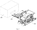
Fig. 1 is a schematic structural diagram of a battery swap system according to an embodiment of the application, -
Fig. 2 is a schematic structural diagram of the battery swap system inFig. 1 bearing a battery pack, -
Fig. 3 is an exploded diagram of the battery swap system inFig. 1 , -
Fig. 4 is an exploded diagram, viewed from another angle, of the battery swap system inFig. 1 comprising a battery pack, and -
Fig. 5 is a schematic diagram of the battery swap system in a working state according to the application. - To help those skilled in the art to clearly understand the subject matter of the application, specific implementations of the application are described below with reference to the accompanying drawings.
- An automated battery swap rail trolley involved in the invention, hereinafter referred to as a rail guided vehicle (RGV), is used for a battery pack swap of an electric vehicle. The RGV is a rail vehicle, which moves to and from a lifting station and a battery compartment along a track rail, wherein an electric vehicle with a battery pack to be swapped enters the lifting station. Herein, the battery pack can also be referred to as a battery, a battery module, etc., and is an integrated device for providing driving power to the electric vehicle. The RGV in a no-load state enters an area below the vehicle in the lifting station, removes a used battery pack from the vehicle, and transfers the used battery pack from the lifting station to the battery compartment. The used battery pack is replaced with a fresh battery pack in the battery compartment. The RGV carrying the fresh battery pack enters the lifting station again, and installs the fresh battery pack in the vehicle. The above work flow is automated, is applicable to small battery swap places and can provide a modularly extended battery swap service.
- Referring to
Figs. 1-4 , anRGV 100 comprisestrack rails 111 arranged in a first direction x, awalking mechanism 10 and a batteryswap executing mechanism 20. Specifically, referring toFigs. 3 and4 , thewalking mechanism 10 comprises anelectric motor 112, a gear (not indicated in the figures), arack 113 and a bearing. Therack 113 substantially parallel to thetrack rails 111, i.e., extending in the first direction x, is arranged between the twotrack rails 111. Theelectric motor 112 is a driving servo motor of the RGV, and is connected to the gear. The gear meshes with therack 113. Theelectric motor 112 is started to drive the gear, and by means of gear-rack transmission, wheels of the RGV move in the form of the bearing in thetrack rails 111. The batteryswap executing mechanism 20 of the RGV movably walks on the track rails by means of the bearing, and moves in the first direction x between a lifting station and a battery compartment along thetrack rails 111. After entering the lifting station to an area below the vehicle along the track rails, the RGV can directly remove or install a battery pack without the need of directional adjustment. The RGV always remains in the direction of the battery pack during the entire battery swap process, bringing many advantages such as reducing the battery swap time and preventing an error caused by undue positioning of the battery pack. - The battery
swap executing mechanism 20 comprises asupport device 21, a conveyingdevice 23 and a floatingdevice 25. The battery swap executing mechanism can enable the conveyingdevice 23 and the floatingdevice 25 to ascend or descend in a second direction y by means of thesupport device 21, and the floatingdevice 25 and the conveyingdevice 23 can also ascend or descend relative to each other. Herein, the second direction y is a vertical direction (i.e. a height direction) as shown in the figures, and the first direction x is a transverse direction along a path connecting the lifting station and the battery compartment. Thesupport device 21 comprises afirst bottom plate 211, a firsttop plate 212 and anelevation driving member 213 between thefirst bottom plate 211 and the firsttop plate 212. Theelevation driving member 213 may be scissors as shown in the figures, and under the action of the scissors, the firsttop plate 212 ascends or descends relative to thefirst bottom plate 211. Thefirst bottom plate 211 is arranged on the ground and between the track rails 111. Thesupport device 21 can be considered as a scissor lift platform as a whole. - The
support device 21 is driven by a rigid chain drivenmotor unit 214 to ascend or descend, the rigid chain drivenmotor unit 214 being disposed at a side of the track rails 111. As can be seen fromFigs. 1-3 , with respect to the battery swap executing mechanism, the rigid chain drivenmotor unit 214 is disposed outside the battery swap executing mechanism, or even outside the entire RGV, thus facilitating the installation and maintenance of the rigid chain driven motor. - The conveying
device 23 is used for transferring a battery pack between the RGV and the battery compartment or other battery pack storage equipment, with its transport direction matching a docking equipment. As an example, as shown inFigs. 3 and4 , the conveyingdevice 23 can transport a battery pack in the first direction x. The conveyingdevice 23 comprises two frames which are parallel to each other in the first direction x as shown in the figures. Aroller array 231 consisting of a plurality of pivotable rollers is arranged in each of the frames. After the conveyingdevice 23 is loaded with the battery pack, the battery pack makes contact with the top of theroller array 231, and the battery pack can move relative to theroller array 231. A surface, which makes contact with the battery and is used to bear and convey the battery, of the conveying device is formed on the surface of theroller array 231, and is defined as a first surface. Theroller array 231 is driven by adriving unit 232. The drivingunit 232 is, for example, an electric motor as shown in the figures. The electric motor drives, by means of acoupling shaft 233 connected between tworoller arrays 231, the rollers in theroller arrays 231 to pivot for transmission movement. The battery pack can be transported in a forward or reverse direction in the first direction x by means of forward or reverse rotation of the electric motor. Definitely, it should be contemplated that, in addition to the arrangement of the driving unit, the roller arrays may also be used to transfer the battery pack in an unpowered manner, which requires manpower to move the battery pack into or out of the battery compartment. - The conveying
device 23 moves in a stepped manner in the second direction y relative to the floatingdevice 25. The floatingdevice 25 is connected to thesupport device 21. The floating device and the support device will be further described below. Herein, what is called "moving in a stepped manner" means stepped movement of two devices relative to each other, wherein one can move independently of the other, and the one can also move together with the other. For example, one moves independently while the other keeps still for the moment; and then the one bears the other to move together or the two move at the same time. In the application, during the entire elevation process (ascending or descending), the floating device ascends or descends independently of the conveying device within a period of time, and ascends or descends together with the conveying device within another period of time. According to the embodiments shown in the figures, without specific limitation, in the lifting process of the battery swap executing mechanism, the floating device ascends first while the conveying device keeps still, and when the floating device ascends to a certain height, the floating device ascends together with the conveying device; and in the descending process of the battery swap executing mechanism, the floating device descends together with the conveying device, and when the conveying device descends to a certain height, the floating device continues to descend while the conveying device keeps still. - On the first
top plate 211 of thesupport device 21,first posts 216 extending in the second direction y are disposed. As shown in the figures, fourfirst posts 216 are arranged at four corners of the first top plate 212 (inFig. 3 , limited by the image display, only two diagonalfirst posts 216 are marked). Correspondingly, guidemechanisms 234 are disposed on an outer side of the frames of the conveyingdevice 23. Theguide mechanisms 234 are specifically four bearing blocks mounted to the frames, and provide therein holes for thefirst posts 216 to pass through. Therefore, after thefirst posts 216 pass through the bearing block, thefirst posts 216 can move in the holes in the second direction y relative to the holes, and after the first post mounting surface (i.e. the surface of the first top plate 212) ascends to make contact with the bearing block, it can be such that thefirst posts 216 and the bearing block, i.e. the first posts 216 (thesupport device 21 and the floating device 25) and the conveyingdevice 23, move upward together. The movement relationship of the two may also be as follows: firstly, the bearing block (the conveying device 23) and the first posts 216 (thesupport device 21 and the floating device 25) move downward together, and when the conveyingdevice 23 is restricted from continuing to move (as shown inFig. 4 , the conveyingdevice 23 is provided withsupport legs 239, and when thesupport legs 239 descend to make contact with the ground, the conveyingdevice 23 stops moving), thefirst posts 216 continue to move relative to the bearing block without detaching from the bearing block. In this case, the floatingdevice 25 moves independently of the conveyingdevice 23. - The floating
device 25 is mounted on thesupport device 21 in a suspended manner. Because of the connection relationship between the floatingdevice 25 and thesupport device 21, the movement of thesupport device 21 in the second direction y causes the floatingdevice 25 to move together with same. In addition, because the floatingdevice 25 is connected to thesupport device 21 in a suspended manner, the floatingdevice 25 can move in some directions or in any direction within a certain range relative to the support device 21 (i.e. the floatingdevice 25 is movable, and thesupport device 21 is stationary). The basic requirement is that under the action of an external force, the floatingdevice 25 at least can float in a plane perpendicular to the second direction y. Herein, what is called "floating" means omni-directional floating, and is neither limited to floating in a plane nor one-dimensional or two-dimensional floating, but may be floating in more directions within a small range, for example, slight three-dimensional movement or slight rotation in other directions. Such floating facilitates the adjustment of the position of the floatingdevice 25 relative to the battery pack, and detailed description will be given below. - The floating
device 25 and thesupport device 21 are spaced apart by a distance in the second direction y, and the floatingdevice 25 is suspended on thesupport device 21. Specifically, the firsttop plate 212 of thesupport device 21 is provided withsecond posts 217 extending in the second direction y, and the entirety or part of the floatingdevice 25 is suspended at the top of the second posts 217. According to the embodiments shown in the figures, without limitation, provided are four second posts 217 (inFig. 3 , limited by the image display, only onesecond post 217 is marked), the second posts are arranged in the center of the firsttop plate 212, every twosecond posts 217 are connected by abeam 218, a chain is suspended from the second posts 217 (or the beam 218), and the second posts 217 (or the beam 218) is connected to the floatingdevice 25 by the chain. In addition, it should be contemplated that a locking device may further be disposed, to lock the floatingdevice 25 relative to thesupport device 21 if necessary. - The floating
device 25 comprises asecond bottom plate 251 and a secondtop plate 252. Thesecond bottom plate 251 is provided with a plurality ofthird posts 253 extending in the second direction y, and thethird posts 253 are fixedly connected to the secondtop plate 252. Therefore, the secondtop plate 252 is stationary relative to thesecond bottom plate 251, and a space exists between the secondtop plate 252 and thesecond bottom plate 251. As mentioned above, the floatingdevice 25 is suspended on thesupport device 21. According to the embodiments shown in the figures, without limitation, thesecond bottom plate 251 of the floatingdevice 25 is connected to the firsttop plate 212 of thesupport device 21 by the chain suspended from thesecond posts 217 or thebeam 218, and a clearance exists in the second direction y between thesecond bottom plate 251 and the firsttop plate 212. The space between thesecond bottom plate 251 and the secondtop plate 252 can be used to arrange the conveyingdevice 23, and a battery locking/unlockingdevice 26 described below such as a torque gun, and acontroller 27 of the torque gun, thus making the RGV of the application have a more compact structure. In addition, the shape of the secondtop plate 252 and thesecond bottom plate 251 is designed to prevent interference with the conveyingdevice 23, so that the floatingdevice 25 can ascend or descend relative to the conveyingdevice 23. As shown inFig. 3 (with reference toFig. 1 ), the secondtop plate 252 is provided with twonotches 259, the area of which substantially corresponding to the size of theroller array 231 so as to accommodate theroller array 231. When the secondtop plate 252 ascends or descends, theroller array 231 is exposed in thenotch 259 and does not interfere with the secondtop plate 252. - The second
top plate 252 is provided withpins 256 and atorque gun socket 257. A plurality ofpins 256 are provided and arranged on the secondtop plate 252 corresponding to the positions of pin holes on the battery pack. The top of thepins 256 can be designed to be chamfered, rounded, tapered, or be other shapes that facilitate the insertion of the pins into the pin holes on the battery pack. A plurality oftorque gun sockets 257 are also provided and arranged on the secondtop plate 252 corresponding to the positions of bolts on the battery pack, and the bolt is a bolt for fixing the battery pack to the vehicle. The number of thepins 256 and thetorque gun sockets 257 depends on the number of pin holes and fixing bolts on the battery pack. The torque gun (which is the main body of the battery locking/unlocking device 26) is arranged below the secondtop plate 252, and is connected to the respectivetorque gun socket 257. The torque gun works to install and remove the bolts. The torque gun is electrically connected to and controlled by a plurality oftorque gun controllers 27, and thetorque gun controllers 27 are arranged in a row and fixed to one end of the conveyingdevice 23 in the first direction x. Thesecond bottom plate 251 is further provided with a plurality offourth posts 254 extending in the second direction y. Thefourth posts 254 are much thicker than the posts described above. Thefourth posts 254 are each provided at the top with apallet 255, which has a main load-bearing function for the battery pack. The secondtop plate 252 is provided with openings 258 for thefourth posts 254, particularly for thepallets 255, thepallets 255 of thefourth posts 254 extend through the openings 258 and beyond the secondtop plate 252, and thepallets 255 form a battery-bearing surface. The height of thepallet 255 is lower than the top of thetorque gun socket 257, making it easy for thetorque gun sockets 257 to extend into the battery. Thepallets 255 are elastically connected to thefourth posts 254 by, for example, a spring, so that thepallets 255 can float to a certain extent in the horizontal direction relative to the fourth posts 254. The size of the opening 258 should not be too small, otherwise it would limit slight floating of thepallet 255. - In summary, the surface, in contact with the battery, of the
roller array 231 is considered as a first surface a, and the second top plate is considered as a second surface b. At an initial position, thesupport legs 239 are on the ground, and the conveying device is at a lowermost position and is spaced apart from the firsttop plate 212 by a distance. In this case, the first surface a is higher than the second surface b so as to bear the battery. The firsttop plate 212 of thesupport device 21 begins to ascend, until the firsttop plate 212 makes contact with the bottom surface of the conveying device and the conveyingdevice 23 is supported by thesupport device 21. When thesupport device 21 continues to ascend, the conveyingdevice 23 moves along with the support device. In this case, the position of the second surface b is higher than that of the first surface c, and the floatingdevice 25 can lock/unlock the battery. - In the descending process, at first, the second surface b is higher than the first surface a. The floating
device 25, the conveyingdevice 23 and thesupport device 21 descend together. They descend until thesupport legs 239 make contact with the ground, and then the conveyingdevice 23 stops moving. The floatingdevice 25 can continue to descend relative to the conveyingdevice 23, until the conveyingdevice 23 bears the battery. In this case, the first surface a is higher than the second surface b. - The battery swap executing mechanism may further be provided with a detection device for detecting and recording a lifting height of the support device. The detection device may be independently disposed on the support device or the floating device. Alternatively, as shown in the figures, a servo motor having a recording function is used as the rigid chain driven
motor unit 214 of thesupport device 21. Acontroller 215 of the servo motor can record a lifting height of the scissor lift platform, and control the scissors to lift the firsttop plate 212 to the recorded height when the next lifting action is required. - The battery swap executing mechanism may further be provided with into-position switches 28 for determining whether the floating device already bears a battery pack. As shown in the figures, without limitation, the into-position switches 28 are disposed on the
beam 218 of the firsttop plate 212, and theswitches 28 can determine whether the floatingdevice 25 already bears the battery by detecting an amount of elastic displacement of thepallets 255. The number of into-position switches 28 corresponds to the number ofpallets 255. - Referring to
Figs. 3-5 , a workflow of the RGV (rolling guide vehicle) of the application is as follows. 1) When there is no battery pack, the servo motor of theRGV 100 is started. A force output by theelectric motor 112 drives, by means of the gear, theRGV 100 to move. By means of gear-rack transmission, the RGV moves along therack 113 and walks on the track rails 111 until same enters the liftingstation 400 to an area directly below a vehicle, the current position being a theoretically set position. In this case, the batteryswap executing mechanism 20 of theRGV 100 is in an initial state (referring toFig. 1 ), thesupport device 21 is at an initial position, and the height of the floating device 25 (i.e. the second surface b of the second top plate 252) is lower than the roller contact surface (the first surface a) of the conveyingdevice 23. - 2) The battery swap executing mechanism operates. Firstly, the
support device 21 is driven by the rigid chain drivenmotor unit 214 to lift the firsttop plate 212, and in this case, the floatingdevice 25 is lifted along with the firsttop plate 212, while the support legs of the conveyingdevice 23 are on the ground. Because of a distance between theguide mechanisms 234 and the first post mounting surface of the firsttop plate 212, thefirst posts 216 move upward in the holes of theguide mechanisms 234, but the guide mechanisms 234 (i.e. the conveying device 23) keep still. The second surface b of the floatingdevice 25 ascends to a position higher than the first surface a of the conveyingdevice 23, until the first post mounting surface makes contact with the bottom of theguide mechanisms 234. Thus, a first lifting action is completed. An initial distance in height between the first post mounting surface and the bottom of theguide mechanisms 234 may be ensured, so as to ensure that when the second surface b is not higher than the conveyingdevice 23, the firsttop plate 212 does not make contact with the bottom of the conveyingdevice 23. - 3) The battery swap executing mechanism performs a second lift. In this case, the
support device 21 is lifted together with the conveyingdevice 23 and the floatingdevice 25, until same approach the battery pack. Thepins 256 on the floatingdevice 25 are aligned with pin holes on the battery pack. Because thepins 256 have a chamfered (tapered) top and the floatingdevice 25 is able to float, thepins 256 can quickly enter the pin holes on the battery pack. After thepins 256 enter the pin holes, it indicates that the floatingdevice 25 has aligned with the battery pack. In this case, the torque gun works, and thetorque gun sockets 257 align with bolts on the battery pack and compress same by a certain stroke, until thepallets 255 begin to make contact with the battery pack below the vehicle body. - 4) The battery swap executing mechanism performs a third lift. The
pallets 255 of the floatingdevice 25 lift the battery pack, until the into-position switches 28 judge and determine that thepallets 255 bear the battery pack. The rigid chain drivenmotor unit 214 of the battery swap executing mechanism records a lifting height for the next lift. - 5) The floating
device 25 is locked relative to thesupport device 21. - 6) The torque gun works to loosen the fixing bolts on the battery pack. The
battery pack 500 is separated from the vehicle. - 7) The battery swap executing mechanism begins to descend. The rigid chain driven
motor unit 214 is started, and the floatingdevice 25 bearing the battery pack, the conveyingdevice 23 and thesupport device 21 descend together, until thesupport legs 239 make contact with the ground. In this case, the floatingdevice 25 bears the battery, and the secondtop plate 252 of the floatingdevice 25 is higher than the roller contact surface (the first surface a) of the conveyingdevice 23. - 8) The support device 21 (the first top plate 212) and the floating
device 25 continue to descend while the conveyingdevice 23 keeps still, until the firsttop plate 212 descends to the initial position. When the bearer for the battery changes from the floatingdevice 25 to the conveyingdevice 23, the first surface a of the conveyingdevice 23 is higher than the second surface b of the floatingdevice 25. The torque gun operates, thesockets 257 are lowered and separated from thebattery pack 500, and thepins 256 are also separated from thebattery pack 500. The floatingdevice 25 is unlocked and returns to the initial state. - 9) The
RGV 100 exits the liftingstation 400 along the track rails 111. - 10) The
RGV 100 exchanges the swapped used battery pack with a fresh battery pack at thebattery compartment 300. - 11) The
RGV 100 carrying the fresh battery pack enters the lifting station again to an area below the vehicle. - 12) The battery swap executing mechanism performs a fourth lift. The
support device 21 drives the floatingdevice 25 to ascend to approach thebattery pack 500, thepins 256 on the secondtop plate 252 of the floatingdevice 25 are inserted into the pin holes on the battery pack again, and thetorque gun sockets 257 align with the bolt holes on the battery pack. When the bearer of thebattery pack 500 changes from the conveyingdevice 23 to the floatingdevice 25 as the floating device ascends, the second surface b of the floatingdevice 25 is higher than the roller contact surface (the first surface a) of the conveyingdevice 23. The into-position switches 28 determine, according to an amount of displacement of the spring below thepallets 255, whether the pallets bear the battery pack. - 13) The battery swap executing mechanism performs a fifth lift. The first post mounting surface of the first
top plate 212 of thesupport device 21 makes contact with theguide mechanisms 234 of the conveyingdevice 23. Thesupport device 21, the floatingdevice 25 bearing the battery pack, and the conveyingdevice 23 are lifted together. The floatingdevice 25 is locked relative to thesupport device 21. - 14) The battery swap executing mechanism performs a sixth lift. According to the recording of the rigid chain driven
motor unit 214, the floatingdevice 25 is lifted to the recorded height. At this height, thebattery pack 500 is in contact with the bottom of the vehicle. - 15) The torque gun works to tighten fixing bolts onto the
battery pack 500. - 16) The
RGV 100 descends in a stepped manner and returns to the initial position, and the floatingdevice 25 is unlocked. - 17) The
RGV 100 exits the liftingstation 400. - Although specific embodiments of the application have been illustrated and described in detail to explain the principles of the application, it should be understood that the application can be implemented in other manners without departing from such principles.
Claims (14)
- A battery swap system, characterized by comprising a battery swap executing mechanism, the battery swap executing mechanism comprising:an elevatable support device (21);a conveying device (23) for battery exchange, the conveying device having a first surface for making contact with a battery; anda floating device (25) having a second surface provided with a battery locking/unlocking device, the floating device (25) being mounted on the support device (21) in a suspended manner and being able to at least horizontally float relative to the support device, whereinthe floating device (25) has a space for elevation relative to the conveying device (23), such that the first surface is higher than the second surface when the conveying device (23) makes contact with the battery, and the second surface is higher than the first surface when the floating device (25) locks/unlocks the battery.
- The battery swap system according to claim 1, characterized in that the support device (21) comprises a first elevatable top plate (212), the floating device (25) comprises a second bottom plate (251) and a second top plate (252) fixed on the second bottom plate (251), and the second bottom plate (251) is suspended on the first top plate (212); and the conveying device is disposed between the second bottom plate (251) and the second top plate (212) in an elevation direction, and the second top plate (212) serves as the second surface.
- The battery swap system according to claim 2, characterized in that the conveying device (23) comprises at least one roller array, the roller array being formed by a plurality of pivotable rollers; and a notch (259) exposing the roller array is provided on the second top plate (252) at a position corresponding to the roller array, and when the floating device (25) ascends or descends relative to the conveying device (23), the roller array switches between a state of being higher than the second top plate (252) and a state of being lower than the second top plate (252) by means of the notch (259).
- The battery swap system according to claim 2, characterized in that the battery locking/unlocking device is a torque gun device, which comprises a torque gun and a socket driven by the torque gun to rotate, wherein the torque gun is disposed on the side of the second top plate (252) that faces the second bottom plate (251) and protrudes out of the second top plate, and the socket is fixed to the side of the second top plate (252) that faces away from the second bottom plate and is in transmission connection with the torque gun.
- The battery swap system according to claim 2, characterized in that the conveying device (23) has a bottom surface facing the first top plate (212) and support legs (239) provided on the bottom surface, and the first top plate (212) is elevatable relative to the bottom surface;
when the support device (21) is at a lowermost position, the conveying device (23) is supported on the support device by means of the support legs (239), so that the first top plate (212) is separated from the bottom surface, and then the first surface is higher than the second surface; and
when the support device (21) ascends, the first top plate (212) ascends along with the support device (21) until making contact with the bottom surface so as to drive the conveying device (23) to ascend synchronously, and then the second surface is higher than the first surface. - The battery swap system according to claim 2, characterized in that the first top plate (212) is provided with first posts (216), the conveying device (23) is provided with guide mechanisms (234), the guide mechanisms (234) provide holes for the first posts (216) to pass through, the first posts (216) move in the holes when the floating device (25) ascends or descends relative to the conveying device (23), and the first posts (216) stand still relative to the holes when the conveying device (23) ascends or descends along with the floating device (25).
- The battery swap system according to claim 2, characterized in that the first top plate (212) is provided with second posts (217), and the second bottom plate (251) is suspended on the second posts (217), so that the floating device (25) floats relative to the battery when the floating device (25) is calibrated to be in a position relative to the battery.
- The battery swap system according to claim 2, characterized in that a space exists between the second bottom plate (251) and the second top plate (252), the second bottom plate and the second top plate are connected by third posts (253) therebetween, and a controller (27) for controlling the battery locking/unlocking device is located in the space.
- The battery swap system according to claim 2, characterized in that the second bottom plate (251) is provided with fourth posts (254), the fourth posts (254) are each provided at the top with a pallet (255), the second top plate (252) is provided with openings for the pallets (255) to pass through, and the pallets (255) are configured to be at least partially higher than the second top plate (252).
- The battery swap system according to claim 9, characterized in that the pallets (255) are elastically connected to the fourth posts (254), so that the pallets (255) float in a horizontal direction relative to the fourth posts (254) and the openings (258).
- The battery swap system according to claim 10, characterized in that the battery swap system further comprises into-position switches (28) for detecting an amount of elastic displacement of the pallets (255) bearing a battery.
- The battery swap system according to claim 1, characterized in that the support device (21) is driven by a rigid chain driven motor unit (214) arranged outside the battery swap system, and the rigid chain driven motor unit (214) is a servo motor which records a lifting height of the support device (21) bearing a battery after the floating device (25) is positionally calibrated, for the next lift of the support device (21).
- The battery swap system according to claim 1, characterized in that the battery swap system further comprises at least one track rail (111) and a walking mechanism (10) along with which the battery swap executing mechanism (20) moves, and the walking mechanism (10) movably walks on the track rail (111) by means of a bearing.
- The battery swap system according to claim 13, characterized in that the walking mechanism (10) further comprises a driving member and a transmission device connected to the driving member, the transmission device comprising a gear and a rack which mesh with each other, the gear being disposed on the battery swap trolley, and the rack (113) being disposed on the track rail (111) and arranged to be substantially parallel to the track rail (111).
Applications Claiming Priority (2)
| Application Number | Priority Date | Filing Date | Title |
|---|---|---|---|
| CN201711035516.XA CN109484368B (en) | 2017-10-30 | 2017-10-30 | Battery replacement system |
| PCT/CN2018/076020 WO2019085326A1 (en) | 2017-10-30 | 2018-02-09 | Battery swap system |
Publications (2)
| Publication Number | Publication Date |
|---|---|
| EP3705359A1 true EP3705359A1 (en) | 2020-09-09 |
| EP3705359A4 EP3705359A4 (en) | 2021-08-11 |
Family
ID=65689059
Family Applications (1)
| Application Number | Title | Priority Date | Filing Date |
|---|---|---|---|
| EP18873527.8A Pending EP3705359A4 (en) | 2017-10-30 | 2018-02-09 | Battery swap system |
Country Status (3)
| Country | Link |
|---|---|
| EP (1) | EP3705359A4 (en) |
| CN (1) | CN109484368B (en) |
| WO (1) | WO2019085326A1 (en) |
Families Citing this family (36)
| Publication number | Priority date | Publication date | Assignee | Title |
|---|---|---|---|---|
| CN111591165A (en) * | 2019-02-19 | 2020-08-28 | 上海蔚来汽车有限公司 | Battery pack conveying device |
| CN109969145B (en) * | 2019-04-29 | 2024-07-05 | 芜湖坚峰汽车科技有限公司 | Slide rail and battery package subassembly |
| CN110001604B (en) * | 2019-05-23 | 2023-11-07 | 河北工业大学 | Electric vehicle battery-changing double-acting end effector |
| CN110371088B (en) * | 2019-06-27 | 2024-06-25 | 博众精工科技股份有限公司 | Power conversion and load shifting device without lateral force floating |
| CN110406504B (en) * | 2019-06-27 | 2020-12-25 | 博众精工科技股份有限公司 | Battery disassembling method based on floating platform |
| CN110379965A (en) * | 2019-06-27 | 2019-10-25 | 博众精工科技股份有限公司 | A kind of floating locating piece |
| CN110696782B (en) * | 2019-09-05 | 2021-06-22 | 浙江吉智新能源汽车科技有限公司 | A power exchange device with floating function |
| CN114851908A (en) * | 2020-01-23 | 2022-08-05 | 奥动新能源汽车科技有限公司 | Battery replacement control method and system, electronic equipment and storage medium |
| CN111231753B (en) * | 2020-01-23 | 2025-02-14 | 奥动新能源汽车科技有限公司 | Battery swapping equipment and battery swapping station including the same |
| CN111891984B (en) * | 2020-06-24 | 2024-07-05 | 天津迦自机器人科技有限公司 | Fork lifting AGV trolley |
| CN118124448A (en) * | 2020-07-06 | 2024-06-04 | 奥动新能源汽车科技有限公司 | How to determine whether the push-disk box and battery pack are locked |
| CN113895287B (en) * | 2020-07-06 | 2024-08-06 | 奥动新能源汽车科技有限公司 | Unlocking device and battery replacement device including the same |
| CN114204201B (en) * | 2020-09-17 | 2024-07-16 | 奥动新能源汽车科技有限公司 | Quick-change battery terminal liquid cooling connection device, battery pack and electric vehicle |
| CN112078421B (en) * | 2020-09-28 | 2024-09-17 | 中国汽车工程研究院股份有限公司 | Liftable translation device for intelligent battery pack replacement of new energy automobile and working method |
| CN112886122A (en) * | 2021-01-06 | 2021-06-01 | 湖北德普智能装备有限公司 | Floating device for automatically replacing battery pack of electric automobile |
| CN112895901A (en) * | 2021-01-29 | 2021-06-04 | 北京海纳川汽车部件股份有限公司 | Protection system of vehicle and vehicle that has it |
| CN112830426A (en) * | 2021-02-04 | 2021-05-25 | 上海玑域智能科技有限公司 | A cam-lifted handling equipment |
| CN113263949B (en) * | 2021-07-06 | 2022-08-09 | 博众精工科技股份有限公司 | Vehicle positioning device and charging and replacing station |
| CN113682190B (en) * | 2021-07-26 | 2022-06-07 | 安徽国防科技职业学院 | Automatic battery replacement system of new energy automobile |
| CN113479109B (en) * | 2021-08-10 | 2023-05-16 | 三一重工股份有限公司 | Electric vehicle power exchanging station |
| CN113860217A (en) * | 2021-08-24 | 2021-12-31 | 深圳东瑞兴联智能科技有限公司 | Horizontal control system and RGV with single track |
| CN113696778B (en) * | 2021-10-29 | 2022-01-18 | 江苏索尔新能源科技股份有限公司 | Battery turnover adjusting device for battery changing station |
| CN115284950B (en) * | 2021-11-30 | 2024-10-18 | 奥动新能源汽车科技有限公司 | Battery swap tray for electric vehicle and electric vehicle |
| CN119749477B (en) * | 2021-12-02 | 2026-03-20 | 奥动新能源股份有限公司 | Vehicle calibration system, battery swapping station and battery swapping method |
| CN116512970B (en) * | 2022-01-20 | 2025-10-21 | 富泰京精密电子(烟台)有限公司 | Battery replacement device, battery replacement method and power supply equipment |
| CN114572051B (en) * | 2022-03-15 | 2023-09-26 | 上海西井科技股份有限公司 | Integrated vehicle battery swapping system, method, equipment and storage medium |
| CN116923180A (en) * | 2022-04-02 | 2023-10-24 | 奥动新能源汽车科技有限公司 | Assembling method of battery replacement equipment |
| CN115285163A (en) * | 2022-04-02 | 2022-11-04 | 奥动新能源汽车科技有限公司 | Battery replacing equipment and walking device comprising same |
| CN115520154B (en) * | 2022-09-22 | 2025-02-14 | 北京胜能能源科技有限公司 | Battery swap station and battery pack sideways placement control method for battery swap station |
| CN115520153B (en) * | 2022-09-22 | 2025-04-25 | 北京胜能能源科技有限公司 | Battery swap station and method for removing battery pack from side of battery swap station |
| JP2025536876A (en) * | 2022-09-23 | 2025-11-12 | 杭州海康机器人股▲ふん▼有限公司 | Battery Swap Station |
| CN116001736B (en) * | 2022-12-22 | 2026-04-24 | 博众精工科技股份有限公司 | Battery swapping methods at battery swapping stations |
| CN115991172B (en) * | 2023-02-21 | 2025-08-08 | 安徽巨一科技股份有限公司 | An AGV battery-changing vehicle |
| CN117465283A (en) * | 2023-12-27 | 2024-01-30 | 宁波格劳博智能工业有限公司 | Battery pack quick-change bracket, battery pack battery replacement station and battery replacement method |
| CN118323053B (en) * | 2024-03-10 | 2024-11-01 | 国瑞供应链有限公司 | Battery dismounting mechanism and method for electric automobile |
| WO2026020465A1 (en) * | 2024-07-26 | 2026-01-29 | 宁德时代新能源科技股份有限公司 | Battery-swapping robot and battery swapping station |
Family Cites Families (13)
| Publication number | Priority date | Publication date | Assignee | Title |
|---|---|---|---|---|
| JP2012006498A (en) * | 2010-06-25 | 2012-01-12 | Hirata Corp | System and method for replacing battery |
| JP5737162B2 (en) * | 2011-12-06 | 2015-06-17 | 株式会社豊田自動織機 | Battery unit mounting device for electric vehicle and battery unit transfer device for electric vehicle |
| IL218949A0 (en) * | 2012-03-29 | 2012-07-31 | Better Place GmbH | Vehicle alignment system for battery switch station |
| JP5444418B2 (en) * | 2012-06-21 | 2014-03-19 | モテックス プロダクツ カンパニー リミテッド | Automatic battery replacement system for electric vehicles |
| US10513247B2 (en) * | 2013-06-19 | 2019-12-24 | Tesla, Inc. | Battery swapping system and techniques |
| US9688252B2 (en) * | 2014-04-23 | 2017-06-27 | Tesla, Inc. | Battery swapping system and techniques |
| CN104842962B (en) * | 2015-04-13 | 2017-02-01 | 深圳精智机器有限公司 | Electricity exchanging equipment |
| CN104787010B (en) * | 2015-04-13 | 2017-09-01 | 深圳精智机器有限公司 | Lowering or hoisting gear and battery replacement device |
| CN106347323B (en) * | 2015-07-15 | 2018-11-20 | 深圳精智机器有限公司 | Lift transport device |
| CN205468600U (en) * | 2016-01-08 | 2016-08-17 | 长安大学 | Electric automobile hydraulic pressure trades electric installation |
| CN205951929U (en) * | 2016-06-22 | 2017-02-15 | 蔚来汽车有限公司 | Small automatic power station |
| CN106043246A (en) * | 2016-06-22 | 2016-10-26 | 蔚来汽车有限公司 | Small-sized automatic power changing station |
| CN107097762B (en) * | 2017-05-15 | 2020-06-30 | 上海蔚来汽车有限公司 | Track-guided battery swapping robot, charging and swapping station, and battery swapping method |
-
2017
- 2017-10-30 CN CN201711035516.XA patent/CN109484368B/en active Active
-
2018
- 2018-02-09 WO PCT/CN2018/076020 patent/WO2019085326A1/en not_active Ceased
- 2018-02-09 EP EP18873527.8A patent/EP3705359A4/en active Pending
Also Published As
| Publication number | Publication date |
|---|---|
| EP3705359A4 (en) | 2021-08-11 |
| CN109484368B (en) | 2022-04-01 |
| WO2019085326A1 (en) | 2019-05-09 |
| CN109484368A (en) | 2019-03-19 |
Similar Documents
| Publication | Publication Date | Title |
|---|---|---|
| EP3705359A1 (en) | Battery swap system | |
| JP7748940B2 (en) | Rescue system and method for recovering a malfunctioning vehicle from a rail system | |
| EP3730359B1 (en) | Battery swapping actuating mechanism | |
| DK2440488T3 (en) | System to replace a battery in a vehicle, particularly a driverless heavy load vehicle to ISO containers | |
| CN218085167U (en) | Charging and battery-replacing station | |
| CN114590165B (en) | Battery buffer device for power exchange station and power exchange station | |
| CN108177634A (en) | Charging and battery-replacing station | |
| KR101977774B1 (en) | Device for installing and uninstalling a vehicle battery | |
| WO2019105458A1 (en) | Battery swapping station and control method therefor | |
| EP2308778A2 (en) | Automated warehouse shuttle | |
| US20240375868A1 (en) | A cam mechanism for a direction-change assembly of a load handling device, and related methods and uses | |
| CN112389258A (en) | Battery changing mobile device | |
| EP3705362A1 (en) | Spring suspension chain type floating device | |
| CN218661761U (en) | Double-bin battery replacing station | |
| CN111231737A (en) | Battery replacing system and battery replacing station comprising same | |
| US20150210519A1 (en) | Stacker crane | |
| CN108860093B (en) | Bottom plate leveling mechanism, track and trade electric installation | |
| US8742721B2 (en) | Battery charging warehouse | |
| CN215042214U (en) | Charging support and battery replacement station | |
| CN219193341U (en) | frame storage line | |
| CN211688081U (en) | Battery swapping mobile device | |
| CN215398264U (en) | Stacking type battery replacement executing mechanism and electric heavy truck side replacement type battery charging and replacing system | |
| WO2023186129A1 (en) | Battery swapping device and battery swapping station comprising same | |
| CN109709968A (en) | Lifting device and automatically guiding trolley | |
| CN214988522U (en) | Cylindrical battery core jacking mechanism and rubber coating device |
Legal Events
| Date | Code | Title | Description |
|---|---|---|---|
| STAA | Information on the status of an ep patent application or granted ep patent |
Free format text: STATUS: THE INTERNATIONAL PUBLICATION HAS BEEN MADE |
|
| PUAI | Public reference made under article 153(3) epc to a published international application that has entered the european phase |
Free format text: ORIGINAL CODE: 0009012 |
|
| STAA | Information on the status of an ep patent application or granted ep patent |
Free format text: STATUS: REQUEST FOR EXAMINATION WAS MADE |
|
| 17P | Request for examination filed |
Effective date: 20200529 |
|
| AK | Designated contracting states |
Kind code of ref document: A1 Designated state(s): AL AT BE BG CH CY CZ DE DK EE ES FI FR GB GR HR HU IE IS IT LI LT LU LV MC MK MT NL NO PL PT RO RS SE SI SK SM TR |
|
| AX | Request for extension of the european patent |
Extension state: BA ME |
|
| RAP1 | Party data changed (applicant data changed or rights of an application transferred) |
Owner name: NIO (ANHUI) HOLDING CO., LTD. |
|
| RIN1 | Information on inventor provided before grant (corrected) |
Inventor name: LI, NAN Inventor name: BENGTSSON, JAN Inventor name: TIAN, XIAOTAO Inventor name: DING, XIKUN |
|
| DAV | Request for validation of the european patent (deleted) | ||
| DAX | Request for extension of the european patent (deleted) | ||
| REG | Reference to a national code |
Ref country code: DE Ref legal event code: R079 Free format text: PREVIOUS MAIN CLASS: B60S0005060000 Ipc: B60L0053800000 |
|
| A4 | Supplementary search report drawn up and despatched |
Effective date: 20210714 |
|
| RIC1 | Information provided on ipc code assigned before grant |
Ipc: B60L 53/80 20190101AFI20210708BHEP Ipc: B60L 53/30 20190101ALI20210708BHEP Ipc: B60S 5/06 20190101ALI20210708BHEP Ipc: B66F 9/075 20060101ALI20210708BHEP |
|
| STAA | Information on the status of an ep patent application or granted ep patent |
Free format text: STATUS: EXAMINATION IS IN PROGRESS |
|
| 17Q | First examination report despatched |
Effective date: 20240513 |