EP3705362A1 - Spring suspension chain type floating device - Google Patents
Spring suspension chain type floating device Download PDFInfo
- Publication number
- EP3705362A1 EP3705362A1 EP18874312.4A EP18874312A EP3705362A1 EP 3705362 A1 EP3705362 A1 EP 3705362A1 EP 18874312 A EP18874312 A EP 18874312A EP 3705362 A1 EP3705362 A1 EP 3705362A1
- Authority
- EP
- European Patent Office
- Prior art keywords
- floating
- suspension
- plate
- fixed base
- base plate
- Prior art date
- Legal status (The legal status is an assumption and is not a legal conclusion. Google has not performed a legal analysis and makes no representation as to the accuracy of the status listed.)
- Pending
Links
- 239000000725 suspension Substances 0.000 title claims abstract description 88
- 238000000034 method Methods 0.000 description 3
- 230000000694 effects Effects 0.000 description 2
- 238000012986 modification Methods 0.000 description 2
- 230000004048 modification Effects 0.000 description 2
- 230000004075 alteration Effects 0.000 description 1
- 230000009286 beneficial effect Effects 0.000 description 1
- 230000006835 compression Effects 0.000 description 1
- 238000007906 compression Methods 0.000 description 1
- 238000010586 diagram Methods 0.000 description 1
- 230000005484 gravity Effects 0.000 description 1
- 238000003466 welding Methods 0.000 description 1
Images
Classifications
-
- B—PERFORMING OPERATIONS; TRANSPORTING
- B60—VEHICLES IN GENERAL
- B60S—SERVICING, CLEANING, REPAIRING, SUPPORTING, LIFTING, OR MANOEUVRING OF VEHICLES, NOT OTHERWISE PROVIDED FOR
- B60S5/00—Servicing, maintaining, repairing, or refitting of vehicles
- B60S5/06—Supplying batteries to, or removing batteries from, vehicles
-
- B—PERFORMING OPERATIONS; TRANSPORTING
- B60—VEHICLES IN GENERAL
- B60L—PROPULSION OF ELECTRICALLY-PROPELLED VEHICLES; SUPPLYING ELECTRIC POWER FOR AUXILIARY EQUIPMENT OF ELECTRICALLY-PROPELLED VEHICLES; ELECTRODYNAMIC BRAKE SYSTEMS FOR VEHICLES IN GENERAL; MAGNETIC SUSPENSION OR LEVITATION FOR VEHICLES; MONITORING OPERATING VARIABLES OF ELECTRICALLY-PROPELLED VEHICLES; ELECTRIC SAFETY DEVICES FOR ELECTRICALLY-PROPELLED VEHICLES
- B60L53/00—Methods of charging batteries, specially adapted for electric vehicles; Charging stations or on-board charging equipment therefor; Exchange of energy storage elements in electric vehicles
- B60L53/80—Exchanging energy storage elements, e.g. removable batteries
-
- B—PERFORMING OPERATIONS; TRANSPORTING
- B60—VEHICLES IN GENERAL
- B60L—PROPULSION OF ELECTRICALLY-PROPELLED VEHICLES; SUPPLYING ELECTRIC POWER FOR AUXILIARY EQUIPMENT OF ELECTRICALLY-PROPELLED VEHICLES; ELECTRODYNAMIC BRAKE SYSTEMS FOR VEHICLES IN GENERAL; MAGNETIC SUSPENSION OR LEVITATION FOR VEHICLES; MONITORING OPERATING VARIABLES OF ELECTRICALLY-PROPELLED VEHICLES; ELECTRIC SAFETY DEVICES FOR ELECTRICALLY-PROPELLED VEHICLES
- B60L53/00—Methods of charging batteries, specially adapted for electric vehicles; Charging stations or on-board charging equipment therefor; Exchange of energy storage elements in electric vehicles
- B60L53/30—Constructional details of charging stations
-
- Y—GENERAL TAGGING OF NEW TECHNOLOGICAL DEVELOPMENTS; GENERAL TAGGING OF CROSS-SECTIONAL TECHNOLOGIES SPANNING OVER SEVERAL SECTIONS OF THE IPC; TECHNICAL SUBJECTS COVERED BY FORMER USPC CROSS-REFERENCE ART COLLECTIONS [XRACs] AND DIGESTS
- Y02—TECHNOLOGIES OR APPLICATIONS FOR MITIGATION OR ADAPTATION AGAINST CLIMATE CHANGE
- Y02T—CLIMATE CHANGE MITIGATION TECHNOLOGIES RELATED TO TRANSPORTATION
- Y02T10/00—Road transport of goods or passengers
- Y02T10/60—Other road transportation technologies with climate change mitigation effect
- Y02T10/70—Energy storage systems for electromobility, e.g. batteries
-
- Y—GENERAL TAGGING OF NEW TECHNOLOGICAL DEVELOPMENTS; GENERAL TAGGING OF CROSS-SECTIONAL TECHNOLOGIES SPANNING OVER SEVERAL SECTIONS OF THE IPC; TECHNICAL SUBJECTS COVERED BY FORMER USPC CROSS-REFERENCE ART COLLECTIONS [XRACs] AND DIGESTS
- Y02—TECHNOLOGIES OR APPLICATIONS FOR MITIGATION OR ADAPTATION AGAINST CLIMATE CHANGE
- Y02T—CLIMATE CHANGE MITIGATION TECHNOLOGIES RELATED TO TRANSPORTATION
- Y02T10/00—Road transport of goods or passengers
- Y02T10/60—Other road transportation technologies with climate change mitigation effect
- Y02T10/7072—Electromobility specific charging systems or methods for batteries, ultracapacitors, supercapacitors or double-layer capacitors
Definitions
- the invention relates to the technical field of battery swapping for an electric vehicle, and in particular to a spring and suspension chain-type floating device.
- a battery pack at the bottom needs to be swapped accurately, and therefore, the position of the vehicle or a battery swap trolley needs to be adjusted.
- the vehicle or the battery swap trolley, etc. is positioned and adjusted, it is inevitable that there will be errors.
- a target object can float freely, that is, the contact face between the battery swap trolley and the battery pack and the support face of the battery swap trolley in contact with the vehicle are floatable, which is realized often by means of a floating device.
- the existing floating device has a small floating range, may not float when subjected to a load, and may not be restored after floating. Therefore, it is very difficult to achieve accurate positioning in the battery swap system, which makes it difficult to accurately and efficiently perform a battery swap process.
- the technical problem to be solved by the invention is to provide a spring and suspension chain-type floating device for use in a battery swap trolley, wherein the floating device can realize X-axis, Y-axis and Z-axis floating, has a large floating amount and a large load-bearing capacity, can be restored and centered, and can perform position locking, so that a battery swap system can be accurately positioned.
- a spring and suspension chain-type floating device which comprises:
- one end of the suspension column is provided with a cross bar, and one end of the connecting portion is connected to the cross bar; and the other end of the suspension column is fixedly connected to the fixed base plate.
- the connecting portion comprises a suspension chain, and two ends of the suspension chain are respectively connected to the cross bar and the floating plate.
- the connecting portion further comprises a suspension shaft extending in a lengthwise direction of the suspension chain; the cross bar is internally provided with a shaft hole through which the suspension shaft passes, and the end, away from the floating plate, of the suspension chain is connected to the suspension shaft; and the suspension shaft is axially movable in the shaft hole to allow the floating plate to float towards or away from the fixed base plate within the floating gap.
- an elastic component is fitted over an extension, and the elastic component is able to be compressed when the suspension shaft moves towards the fixed base plate, and provides a restoring force.
- the elastic component comprises one or more springs.
- the device further comprises a locking portion for locking the floating plate when the target object is adjusted to a target position.
- the device comprises a plurality of locking portions evenly distributed in a circumferential direction around the floating plate.
- the locking portion is an electromagnetic brake attraction plate which is arranged above the floating plate and oriented in a direction toward the fixed base plate, a through hole corresponding to the brake attraction plate is provided in the floating plate, and during locking, the brake attraction plate passes through the through hole to attract the fixed base plate, so as to lock the floating plate.
- a battery swap trolley which comprises the spring and suspension chain-type floating device.
- the spring and suspension chain-type floating device of the invention can achieve considerable technical progress and practicality, has a wide range of industrial utility value, and has at least the following advantages:
- the invention provides a spring and suspension chain-type floating device, as shown in Figs. 1 and 2 , comprising: a fixed base plate 1, a floating plate 2, suspension columns 3 and connecting portions 4, wherein the fixed base plate 1 and the floating plate 2 are arranged face to face with a floating gap 5 therebetween, and the floating plate 2 is used to support a target object.
- the target object is an object to be aligned or positioned.
- the target object is a battery pack.
- the fixed base plate 1 is provided with one or more pairs of suspension columns 3, the bottom end of the suspension column 3 is fixedly connected to the fixed base plate 1 by means of welding connection, bolted connection, etc.
- Each pair of suspension columns 3 is arranged face to face on an edge of the floating plate 2.
- One end of the connecting portion 4 is connected to the suspension column 3 and the other end thereof is connected to the floating plate 2, and the connecting portion 4 allows the floating plate 2 to float relative to the fixed base plate 1.
- the connecting portion 4 allows the floating plate 2 to float relative to the fixed base plate 1, realizing the floating in the X-axis and Y-axis directions.
- the floating gap 5 prevents the floating plate 2 from making contact with the fixed base plate 1 when the floating plate floats relative to the fixed base plate 1.
- the size of the floating gap 5 is determined according to factors such as the load-bearing capacity to the target object and the maximum range of the target object floating in the X-axis, Y-axis and Z-axis.
- the preferred range of the size of the floating gap 5 is from 1 mm to 20 mm, and in this embodiment, the floating gap 5 is set to be 10 mm.
- the floating plate 2 When the target object on the floating plate 2 is not subjected to any external force or the target object is removed from the floating plate, the floating plate 2 will return to an initial position by its own weight to realize restoring in the X-axis and Y-axis directions. When the next target object is placed on the floating plate 2 to float in the X-axis and Y-axis directions, the floating device will maintain the original floating amount.
- each suspension column 3 is provided with a cross bar 6, and one end of the connecting portion 4 is connected to the cross bar 6; and the other end of the suspension column 3 is fixedly connected to the fixed base plate 1.
- the connecting portion 4 comprises a suspension chain 7, and two ends of the suspension chain 7 are respectively connected to the cross bar 6 and the floating plate 2.
- the connecting portion 4 further comprises a suspension shaft 8 extending in the lengthwise direction of the suspension chain 7; the cross bar 6 is internally provided with a shaft hole 61 through which the suspension shaft 8 extends, and the end, away from the floating plate 2, of the suspension chain 7 is connected to the suspension shaft 8; and the suspension shaft 8 is axially movable in the shaft hole 61 to allow the floating plate 2 to float towards or away from the fixed base plate 1 within the floating gap 5, thereby realizing floating in the Z-axis direction.
- an elastic component 9 is fitted over an extension, and the elastic component 9 is able to be compressed when the suspension shaft 8 moves towards the fixed base plate 1, and provides a restoring force, so as to restore the floating plate 2 in the Z-axis direction.
- an upper end of the elastic component 9 may be fixed on the suspension shaft 8, or a nut or other stop member, etc., may be provided at an upper end of the suspension shaft 8.
- the elastic component 9 is provided to be able to counterbalance the weight of a suspended object, and to achieve the floating of the suspended object in the Z-axis.
- the suspended object comprises the floating plate 2 and the target object.
- the connecting portion 4 further comprises a suspension chain bolt 10.
- the chain bolt 10 is arranged on the floating plate 2.
- the suspension chain 9 is connected to the chain bolt 10 at one end and is connected to the floating plate 2 via the chain bolt 10.
- two pairs of suspension columns 3 are arranged on the fixed base plate 1, and the center of gravity of the suspended object is at the center of the area surrounded by the four suspension columns 3.
- the number of the suspension columns 3 is not limited to 4, and any arrangement enabling the floating plate to float in the X-axis, Y-axis and Z-axis directions is applicable here.
- the elastic component 9 comprises one or more springs arranged in the vertical direction, one or more of which are superposed together.
- the elastic coefficient of the spring may be selected according to factors such as the floating amount and the load-bearing capacity of the floating device.
- the weight of the target object can be determined according to the amount of deformation of the spring so as to control a hoisting force.
- the device further comprises a locking portion 11.
- One or more locking portions 11 may be provided for locking the floating plate 2 when the target object is adjusted to a target position, so that the floating plate 2 cannot move relative to the fixed base plate 1, so as to perform corresponding operations on the target object.
- the device is arranged on the battery swap trolley, and after the position of the battery pack is aligned with the battery swap position, the floating plate 2 is locked by means of the locking portion 11, and in turn the position of the battery pack is also fixed, and then the battery swap operation can be performed.
- the battery swapping precision and accuracy of the battery swap system are increased by means of the device.
- the device comprises four locking portions 11 evenly distributed around the floating plate 2 in the circumferential direction so as to keep the floating plate 2 in a stable state during locking, to prevent slight movement of the target object and to improve the positioning and aligning accuracy of the target object to further improve the accuracy of the battery swap process.
- the locking portion 11 may be an electromagnetic brake attraction plate arranged above the floating plate 2.
- the brake attraction plate faces the fixed base plate 1, and the fixed base plate 1 serves as an attraction face of the brake attraction plate.
- the floating plate 2 is provided with a through hole 12 corresponding to the brake attraction plate. During locking, the brake attraction plate passes through the through hole to attract the fixed base plate 1, so as to lock the floating plate 2.
- the electromagnetic brake attraction plate can be controlled to attract or release the fixed base plate 1 by means of powering on or off the electromagnetic brake attraction plate. In the released state, the locking portion 11 floats along with the floating of the floating plate 2.
- the electromagnetic brake attraction plate can be directly selected from the existing finished products, so the specific structural components thereof are not to be described in detail herein.
- the locking portion 11 using the electromagnetic brake attraction plate is only a preferred embodiment, and other locking portions may be used in other embodiments, as long as the floating plate 2 can be locked when the target object reaches a pre-set position.
- the embodiment of the invention further provides a battery swap trolley.
- the battery swap trolley comprises the spring and the suspension chain-type floating device. During battery swapping, the battery pack is placed on the floating device. If the battery swap position is not accurate, the battery pack is pushed to drive the floating plate to float in the X-axis, Y-axis and Z-axis directions, thereby adjusting the position of the battery pack.
- the floating device of the embodiment of the invention is simple in structure, can float in X, Y and Z directions, has a large floating amount and a large load-bearing capacity, can be restored, and can perform position locking, thereby increasing the positioning precision.
- the floating device can be used to position and align a target in a battery swap system to eliminate the influence of positional errors, thereby increasing the efficiency and accuracy of the battery swap system.
Landscapes
- Engineering & Computer Science (AREA)
- Mechanical Engineering (AREA)
- Power Engineering (AREA)
- Transportation (AREA)
- Battery Mounting, Suspending (AREA)
- Current-Collector Devices For Electrically Propelled Vehicles (AREA)
- Springs (AREA)
Abstract
Description
- The invention relates to the technical field of battery swapping for an electric vehicle, and in particular to a spring and suspension chain-type floating device.
- With the popularization of electric vehicles, how to provide electric energy replenishment for an electric vehicle with insufficient electric power in time and efficiently has become a major concern for both manufacturers and vehicle owners. By means of the establishment of a battery swap system for battery swapping of the electric vehicle, i.e., directly swapping a completely drained traction battery for a fully charged traction battery, the replenishment of electric energy can be completed within minutes, so that battery swapping is a very efficient way for replenishing electric energy.
- In the process of battery swapping by means of the battery swap system, a battery pack at the bottom needs to be swapped accurately, and therefore, the position of the vehicle or a battery swap trolley needs to be adjusted. However, when the vehicle or the battery swap trolley, etc., is positioned and adjusted, it is inevitable that there will be errors. In order to perform the positioning and aligning operations smoothly, it is desirable that a target object can float freely, that is, the contact face between the battery swap trolley and the battery pack and the support face of the battery swap trolley in contact with the vehicle are floatable, which is realized often by means of a floating device. However, the existing floating device has a small floating range, may not float when subjected to a load, and may not be restored after floating. Therefore, it is very difficult to achieve accurate positioning in the battery swap system, which makes it difficult to accurately and efficiently perform a battery swap process.
- The technical problem to be solved by the invention is to provide a spring and suspension chain-type floating device for use in a battery swap trolley, wherein the floating device can realize X-axis, Y-axis and Z-axis floating, has a large floating amount and a large load-bearing capacity, can be restored and centered, and can perform position locking, so that a battery swap system can be accurately positioned.
- In order to solve the above technical problem, according to an aspect of the invention, provided is a spring and suspension chain-type floating device, which comprises:
- a fixed base plate, a floating plate, suspension columns and connecting portions, wherein
- the fixed base plate and the floating plate are arranged face to face with a floating gap therebetween, and the floating plate is used to support a target object;
- the fixed base plate is provided with one or more pairs of suspension columns, each pair of suspension columns being arranged face to face on an edge of the floating plate; and
- one end of the connecting portion is connected to the suspension column and the other end thereof is connected to the floating plate, and the connecting portion allows the floating plate to float relative to the fixed base plate.
- Further, one end of the suspension column is provided with a cross bar, and one end of the connecting portion is connected to the cross bar; and
the other end of the suspension column is fixedly connected to the fixed base plate. - Further, the connecting portion comprises a suspension chain, and two ends of the suspension chain are respectively connected to the cross bar and the floating plate.
- Further, the connecting portion further comprises a suspension shaft extending in a lengthwise direction of the suspension chain;
the cross bar is internally provided with a shaft hole through which the suspension shaft passes, and the end, away from the floating plate, of the suspension chain is connected to the suspension shaft; and
the suspension shaft is axially movable in the shaft hole to allow the floating plate to float towards or away from the fixed base plate within the floating gap. - Further, The end, facing away from the suspension chain, of the suspension shaft extends out of the cross bar, an elastic component is fitted over an extension, and the elastic component is able to be compressed when the suspension shaft moves towards the fixed base plate, and provides a restoring force.
- Further, the elastic component comprises one or more springs.
- Further, the device further comprises a locking portion for locking the floating plate when the target object is adjusted to a target position.
- Further, the device comprises a plurality of locking portions evenly distributed in a circumferential direction around the floating plate.
- Further, the locking portion is an electromagnetic brake attraction plate which is arranged above the floating plate and oriented in a direction toward the fixed base plate, a through hole corresponding to the brake attraction plate is provided in the floating plate, and during locking, the brake attraction plate passes through the through hole to attract the fixed base plate, so as to lock the floating plate.
- According to another aspect of the invention, provided is a battery swap trolley which comprises the spring and suspension chain-type floating device.
- The invention has obvious advantages and beneficial effects as compared with the prior art. By means of the above technical solutions, the spring and suspension chain-type floating device of the invention can achieve considerable technical progress and practicality, has a wide range of industrial utility value, and has at least the following advantages:
- (1) the floating device is simple in structure, can float in X, Y and Z directions, and can be used to position and align a target in a battery swap system to eliminate the influence of positional errors; and
- (2) the floating device has a large floating amount and a large load-bearing capacity, can be restored, and can perform position locking, thereby increasing the positioning precision.
- The aforementioned description is only an overview of the technical solutions of the invention. In order to clearly understand the technical means of the invention, the invention can be implemented according to the contents of the description; and in order to make the aforementioned and other objects, features and advantages of the invention more obvious and understandable, preferred embodiments are described in detail below with reference to the accompanying drawings.
-
-
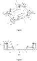
Fig. 1 is a schematic diagram of a spring and suspension chain-type floating device provided in an embodiment of the invention. -
Fig. 2 is a sectional view taken along line A-A ofFig. 1 . -
1: Fixed base plate 2: Floating plate 3: Suspension column 4: Connecting portion 5: Floating gap 6: Cross bar 7: Suspension chain 8: Suspension shaft 9: Elastic component 10: Chain bolt 11: Locking portion - In order to further illustrate the technical means used to achieve the intended purpose of the invention and the technical effects of the invention, the implementation of a spring and suspension chain-type floating device proposed in the invention and the effects thereof are described in detail hereinafter in conjunction with the accompanying drawings and the preferred embodiments.
- The invention provides a spring and suspension chain-type floating device, as shown in
Figs. 1 and 2 , comprising:
afixed base plate 1, a floating plate 2,suspension columns 3 and connectingportions 4, wherein thefixed base plate 1 and the floating plate 2 are arranged face to face with afloating gap 5 therebetween, and the floating plate 2 is used to support a target object. The target object is an object to be aligned or positioned. For example, when the floating device is applied to a battery swap trolley in a battery swap system, the target object is a battery pack. Thefixed base plate 1 is provided with one or more pairs ofsuspension columns 3, the bottom end of thesuspension column 3 is fixedly connected to thefixed base plate 1 by means of welding connection, bolted connection, etc. Each pair ofsuspension columns 3 is arranged face to face on an edge of the floating plate 2. One end of the connectingportion 4 is connected to thesuspension column 3 and the other end thereof is connected to the floating plate 2, and the connectingportion 4 allows the floating plate 2 to float relative to thefixed base plate 1. - It is assumed that the horizontal direction is the X-axis, the direction perpendicular to the X-axis direction in a horizontal plane is the Y-axis, and the vertical direction is the Z-axis. The connecting
portion 4 allows the floating plate 2 to float relative to thefixed base plate 1, realizing the floating in the X-axis and Y-axis directions. Thefloating gap 5 prevents the floating plate 2 from making contact with thefixed base plate 1 when the floating plate floats relative to thefixed base plate 1. The size of thefloating gap 5 is determined according to factors such as the load-bearing capacity to the target object and the maximum range of the target object floating in the X-axis, Y-axis and Z-axis. The preferred range of the size of thefloating gap 5 is from 1 mm to 20 mm, and in this embodiment, thefloating gap 5 is set to be 10 mm. - When the target object on the floating plate 2 is not subjected to any external force or the target object is removed from the floating plate, the floating plate 2 will return to an initial position by its own weight to realize restoring in the X-axis and Y-axis directions. When the next target object is placed on the floating plate 2 to float in the X-axis and Y-axis directions, the floating device will maintain the original floating amount.
- One end of each
suspension column 3 is provided with across bar 6, and one end of the connectingportion 4 is connected to thecross bar 6; and the other end of thesuspension column 3 is fixedly connected to thefixed base plate 1. - The connecting
portion 4 comprises asuspension chain 7, and two ends of thesuspension chain 7 are respectively connected to thecross bar 6 and the floating plate 2. The connectingportion 4 further comprises asuspension shaft 8 extending in the lengthwise direction of thesuspension chain 7; thecross bar 6 is internally provided with a shaft hole 61 through which thesuspension shaft 8 extends, and the end, away from the floating plate 2, of thesuspension chain 7 is connected to thesuspension shaft 8; and thesuspension shaft 8 is axially movable in the shaft hole 61 to allow the floating plate 2 to float towards or away from thefixed base plate 1 within thefloating gap 5, thereby realizing floating in the Z-axis direction. - The end, facing away from the
suspension chain 7, of thesuspension shaft 8 extends out of the cross bar, an elastic component 9 is fitted over an extension, and the elastic component 9 is able to be compressed when thesuspension shaft 8 moves towards thefixed base plate 1, and provides a restoring force, so as to restore the floating plate 2 in the Z-axis direction. In some examples, in order to better achieve the compression of the elastic component 9 along with the downward movement of thesuspension shaft 8, an upper end of the elastic component 9 may be fixed on thesuspension shaft 8, or a nut or other stop member, etc., may be provided at an upper end of thesuspension shaft 8. The elastic component 9 is provided to be able to counterbalance the weight of a suspended object, and to achieve the floating of the suspended object in the Z-axis. The suspended object comprises the floating plate 2 and the target object. - In some examples, the connecting
portion 4 further comprises asuspension chain bolt 10. Thechain bolt 10 is arranged on the floating plate 2. The suspension chain 9 is connected to thechain bolt 10 at one end and is connected to the floating plate 2 via thechain bolt 10. - In some examples, two pairs of
suspension columns 3 are arranged on the fixedbase plate 1, and the center of gravity of the suspended object is at the center of the area surrounded by the foursuspension columns 3. The number of thesuspension columns 3 is not limited to 4, and any arrangement enabling the floating plate to float in the X-axis, Y-axis and Z-axis directions is applicable here. - In some examples, the elastic component 9 comprises one or more springs arranged in the vertical direction, one or more of which are superposed together. The elastic coefficient of the spring may be selected according to factors such as the floating amount and the load-bearing capacity of the floating device. In addition, according to the parameters of the selected spring, the weight of the target object can be determined according to the amount of deformation of the spring so as to control a hoisting force.
- In some examples, the device further comprises a locking
portion 11. One ormore locking portions 11 may be provided for locking the floating plate 2 when the target object is adjusted to a target position, so that the floating plate 2 cannot move relative to the fixedbase plate 1, so as to perform corresponding operations on the target object. For example, the device is arranged on the battery swap trolley, and after the position of the battery pack is aligned with the battery swap position, the floating plate 2 is locked by means of the lockingportion 11, and in turn the position of the battery pack is also fixed, and then the battery swap operation can be performed. The battery swapping precision and accuracy of the battery swap system are increased by means of the device. - In some examples, the device comprises four locking
portions 11 evenly distributed around the floating plate 2 in the circumferential direction so as to keep the floating plate 2 in a stable state during locking, to prevent slight movement of the target object and to improve the positioning and aligning accuracy of the target object to further improve the accuracy of the battery swap process. - The locking
portion 11 may be an electromagnetic brake attraction plate arranged above the floating plate 2. The brake attraction plate faces the fixedbase plate 1, and the fixedbase plate 1 serves as an attraction face of the brake attraction plate. The floating plate 2 is provided with a throughhole 12 corresponding to the brake attraction plate. During locking, the brake attraction plate passes through the through hole to attract the fixedbase plate 1, so as to lock the floating plate 2. The electromagnetic brake attraction plate can be controlled to attract or release the fixedbase plate 1 by means of powering on or off the electromagnetic brake attraction plate. In the released state, the lockingportion 11 floats along with the floating of the floating plate 2. The electromagnetic brake attraction plate can be directly selected from the existing finished products, so the specific structural components thereof are not to be described in detail herein. - It should be noted that the locking
portion 11 using the electromagnetic brake attraction plate is only a preferred embodiment, and other locking portions may be used in other embodiments, as long as the floating plate 2 can be locked when the target object reaches a pre-set position. - The embodiment of the invention further provides a battery swap trolley. The battery swap trolley comprises the spring and the suspension chain-type floating device. During battery swapping, the battery pack is placed on the floating device. If the battery swap position is not accurate, the battery pack is pushed to drive the floating plate to float in the X-axis, Y-axis and Z-axis directions, thereby adjusting the position of the battery pack.
- The floating device of the embodiment of the invention is simple in structure, can float in X, Y and Z directions, has a large floating amount and a large load-bearing capacity, can be restored, and can perform position locking, thereby increasing the positioning precision. The floating device can be used to position and align a target in a battery swap system to eliminate the influence of positional errors, thereby increasing the efficiency and accuracy of the battery swap system.
- The foregoing descriptions are merely preferred embodiments of the invention, and are not intended to limit the invention in any form. Although the invention has been disclosed as above by means of the preferred embodiments, these embodiments are not for the purpose of limiting the invention. Those skilled in the art can make alterations or modifications to the technical contents disclosed above without departing from the technical solutions of the invention so as to arrive at equivalent embodiments with equivalent changes. However, any simple amendments, equivalent changes and modifications made to the above embodiments according to the technical essence of the invention without departing from the technical solutions of the invention are still within the scope of the technical solutions of the invention.
Claims (10)
- A spring and suspension chain-type floating device, characterized by comprising:a fixed base plate, a floating plate, suspension columns and connecting portions, whereinthe fixed base plate and the floating plate are arranged face to face with a floating gap therebetween, and the floating plate is used to support a target object;the fixed base plate is provided with one or more pairs of suspension columns, each pair of suspension columns being arranged face to face on an edge of the floating plate; andone end of the connecting portion is connected to the suspension column and the other end thereof is connected to the floating plate, and the connecting portion allows the floating plate to float relative to the fixed base plate.
- The spring and suspension chain-type floating device according to claim 1, characterized in that
one end of the suspension column is provided with a cross bar, and one end of the connecting portion is connected to the cross bar; and
the other end of the suspension column is fixedly connected to the fixed base plate. - The spring and suspension chain-type floating device according to claim 2, characterized in that
the connecting portion comprises a suspension chain, and two ends of the suspension chain are respectively connected to the cross bar and the floating plate. - The spring and suspension chain-type floating device according to claim 3, characterized in that the connecting portion further comprises a suspension shaft extending in a lengthwise direction of the suspension chain;
the cross bar is internally provided with a shaft hole through which the suspension shaft passes, and the end, away from the floating plate, of the suspension chain is connected to the suspension shaft; and
the suspension shaft is axially movable in the shaft hole to allow the floating plate to float towards or away from the fixed base plate within the floating gap. - The spring and suspension chain-type floating device according to claim 3, characterized in that
the end, facing away from the suspension chain, of the suspension shaft extends out of the cross bar, an elastic component is fitted over an extension, and the elastic component is able to be compressed when the suspension shaft moves towards the fixed base plate, and provides a restoring force. - The spring and suspension chain-type floating device according to claim 4, characterized in that
the elastic component comprises one or more springs. - The spring and suspension chain-type floating device according to claim 1, characterized in that
the device further comprises a locking portion for locking the floating plate when the target object is adjusted to a target position. - The spring and suspension chain-type floating device according to claim 7, characterized in that
the device comprises a plurality of locking portions evenly distributed in a circumferential direction around the floating plate. - The spring and suspension chain-type floating device according to claim 7, characterized in that
the locking portion is an electromagnetic brake attraction plate which is arranged above the floating plate and oriented in a direction toward the fixed base plate, a through hole corresponding to the brake attraction plate is provided in the floating plate, and during locking, the brake attraction plate passes through the through hole to attract the fixed base plate, so as to lock the floating plate. - A battery swap trolley, characterized in that the battery swap trolley comprises the spring and suspension chain-type floating device as claimed in any one of claims 1-9.
Applications Claiming Priority (2)
| Application Number | Priority Date | Filing Date | Title |
|---|---|---|---|
| CN201711033786.7A CN109501746A (en) | 2017-10-30 | 2017-10-30 | Spring suspension chain type floating device |
| PCT/CN2018/084886 WO2019085417A1 (en) | 2017-10-30 | 2018-04-27 | Spring suspension chain type floating device |
Publications (2)
| Publication Number | Publication Date |
|---|---|
| EP3705362A1 true EP3705362A1 (en) | 2020-09-09 |
| EP3705362A4 EP3705362A4 (en) | 2021-08-25 |
Family
ID=65745336
Family Applications (1)
| Application Number | Title | Priority Date | Filing Date |
|---|---|---|---|
| EP18874312.4A Pending EP3705362A4 (en) | 2017-10-30 | 2018-04-27 | Spring suspension chain type floating device |
Country Status (4)
| Country | Link |
|---|---|
| EP (1) | EP3705362A4 (en) |
| CN (1) | CN109501746A (en) |
| TW (2) | TWI665108B (en) |
| WO (1) | WO2019085417A1 (en) |
Cited By (1)
| Publication number | Priority date | Publication date | Assignee | Title |
|---|---|---|---|---|
| EP4234314A4 (en) * | 2020-11-20 | 2025-01-15 | Geely Holding Group Co Ltd | VEHICLE BATTERY CHANGING DEVICE, DUAL FLOATING LIFTING BATTERY CHANGING STATION AND BATTERY CHANGING SYSTEM |
Families Citing this family (4)
| Publication number | Priority date | Publication date | Assignee | Title |
|---|---|---|---|---|
| CN110406504B (en) * | 2019-06-27 | 2020-12-25 | 博众精工科技股份有限公司 | Battery disassembling method based on floating platform |
| CN110562214B (en) * | 2019-09-12 | 2024-06-25 | 博众精工科技股份有限公司 | Floating switching mechanism and floating level changing table |
| CN112886122A (en) * | 2021-01-06 | 2021-06-01 | 湖北德普智能装备有限公司 | Floating device for automatically replacing battery pack of electric automobile |
| CN116895977B (en) * | 2023-07-27 | 2024-05-10 | 马鞍山南实科技有限公司 | Multi-degree-of-freedom plug floating butt joint mechanism and butt joint method |
Family Cites Families (17)
| Publication number | Priority date | Publication date | Assignee | Title |
|---|---|---|---|---|
| KR100482560B1 (en) * | 2002-06-25 | 2005-04-14 | 현대자동차주식회사 | Floating apparatus using electromagnet |
| EP1864940A1 (en) * | 2006-06-08 | 2007-12-12 | Still Gmbh | Industrial truck with a lateral removably power supply unit |
| CN201595517U (en) * | 2009-08-11 | 2010-10-06 | 王国汉 | Floating bionic cradle |
| US8858152B1 (en) * | 2010-05-06 | 2014-10-14 | Steven D. McDaniel | System for replacing batteries in electric cars |
| CN202145510U (en) * | 2011-04-29 | 2012-02-15 | 南京康尼科技实业有限公司 | Floating connector |
| CN102992012B (en) * | 2011-09-15 | 2015-07-15 | 鸿富锦精密工业(深圳)有限公司 | Positioning mechanism |
| CN202231261U (en) * | 2011-09-28 | 2012-05-23 | 普天新能源有限责任公司 | Floating connecting device of power battery box of electric automobile |
| CN102602410B (en) * | 2012-03-20 | 2015-04-15 | 浙江双友物流器械股份有限公司 | Fixed frame of steel rails |
| CN203047214U (en) * | 2012-11-09 | 2013-07-10 | 深圳市许继自动化技术有限公司 | Push-pull system of electric-switching robot and electric-switching robot |
| CN102991475B (en) * | 2012-11-09 | 2015-09-23 | 王俊 | Change the push-pull system of electric machine people and change electric machine people |
| CN104045022B (en) * | 2013-03-15 | 2017-10-27 | 北京科易动力科技有限公司 | A kind of automatically reset floating platform of energy |
| CN104019167A (en) * | 2014-06-12 | 2014-09-03 | 苏州劳灵精密机械有限公司 | Compression spring thrust-tension conversion device |
| CN106347323B (en) * | 2015-07-15 | 2018-11-20 | 深圳精智机器有限公司 | Lift transport device |
| CN205892646U (en) * | 2016-08-09 | 2017-01-18 | 浙江科钛机器人股份有限公司 | From floating climbing mechanism |
| CN206231369U (en) * | 2016-11-17 | 2017-06-09 | 蔚来汽车有限公司 | Floating alignment device for battery replacement equipment |
| CN106926825B (en) * | 2016-11-17 | 2019-10-15 | 蔚来汽车有限公司 | Floating alignment apparatus and method for swapping devices |
| CN207579841U (en) * | 2017-10-30 | 2018-07-06 | 蔚来汽车有限公司 | Spring suspension chain type floating device and battery replacing trolley |
-
2017
- 2017-10-30 CN CN201711033786.7A patent/CN109501746A/en active Pending
-
2018
- 2018-04-27 WO PCT/CN2018/084886 patent/WO2019085417A1/en unknown
- 2018-04-27 EP EP18874312.4A patent/EP3705362A4/en active Pending
- 2018-06-08 TW TW107120100A patent/TWI665108B/en active
- 2018-06-08 TW TW107207830U patent/TWM572317U/en unknown
Cited By (1)
| Publication number | Priority date | Publication date | Assignee | Title |
|---|---|---|---|---|
| EP4234314A4 (en) * | 2020-11-20 | 2025-01-15 | Geely Holding Group Co Ltd | VEHICLE BATTERY CHANGING DEVICE, DUAL FLOATING LIFTING BATTERY CHANGING STATION AND BATTERY CHANGING SYSTEM |
Also Published As
| Publication number | Publication date |
|---|---|
| TWM572317U (en) | 2019-01-01 |
| EP3705362A4 (en) | 2021-08-25 |
| TWI665108B (en) | 2019-07-11 |
| CN109501746A (en) | 2019-03-22 |
| WO2019085417A1 (en) | 2019-05-09 |
| TW201917039A (en) | 2019-05-01 |
Similar Documents
| Publication | Publication Date | Title |
|---|---|---|
| EP3705362A1 (en) | Spring suspension chain type floating device | |
| CN207579841U (en) | Spring suspension chain type floating device and battery replacing trolley | |
| CN109515402B (en) | Electric vehicle charging and battery changing system adopting cantilever beam | |
| US10644344B1 (en) | Clamping apparatus and transport device | |
| EP3683107A1 (en) | Vehicle position adjusting apparatus | |
| CN102405160B (en) | Device for moving and attaching a component between two positions | |
| KR102043902B1 (en) | Electrode Stacking Device for Secondary Cell | |
| CN109515403B (en) | Electric vehicle charging and battery changing system adopting AGV trolley | |
| CN208276925U (en) | It is a kind of for grabbing the fixture of battery modules | |
| EP3778322A1 (en) | Floating device, battery swapping equipment, and battery swapping station | |
| CN208085685U (en) | Positioning device and power exchange equipment | |
| CN103287646A (en) | Pressing attaching device | |
| CN212810258U (en) | Mechanism for enhancing stability of silicon wafer inserting sheet cleaning machine inserting sheet | |
| CN208085686U (en) | Floating devices, power exchange equipment and power exchange stations | |
| CN218939619U (en) | Semiconductor process equipment and transfer supporting device thereof | |
| CN206606980U (en) | A kind of hydraulic lifting Cargo Lift goods shelf positioning device | |
| WO2022069130A1 (en) | Contactless conveyor device | |
| CN211281895U (en) | Mobile protection device for artificial intelligent robot | |
| CN211003540U (en) | Heavy-load strip-shaped plate feeding machine | |
| CN220516811U (en) | Portal frame manipulator | |
| CN207593793U (en) | A kind of anti-seismic structure and its welding manipulator | |
| EP4216328A2 (en) | Material transferring apparatus for battery manufacturing | |
| CN215787836U (en) | Positioning device | |
| CN219669461U (en) | Blue film up-down alternating device of energy storage battery pack | |
| CN215621513U (en) | Fork structure based on trade electric robot |
Legal Events
| Date | Code | Title | Description |
|---|---|---|---|
| STAA | Information on the status of an ep patent application or granted ep patent |
Free format text: STATUS: THE INTERNATIONAL PUBLICATION HAS BEEN MADE |
|
| PUAI | Public reference made under article 153(3) epc to a published international application that has entered the european phase |
Free format text: ORIGINAL CODE: 0009012 |
|
| STAA | Information on the status of an ep patent application or granted ep patent |
Free format text: STATUS: REQUEST FOR EXAMINATION WAS MADE |
|
| 17P | Request for examination filed |
Effective date: 20200529 |
|
| AK | Designated contracting states |
Kind code of ref document: A1 Designated state(s): AL AT BE BG CH CY CZ DE DK EE ES FI FR GB GR HR HU IE IS IT LI LT LU LV MC MK MT NL NO PL PT RO RS SE SI SK SM TR |
|
| AX | Request for extension of the european patent |
Extension state: BA ME |
|
| RAP1 | Party data changed (applicant data changed or rights of an application transferred) |
Owner name: NIO (ANHUI) HOLDING CO., LTD. |
|
| RIN1 | Information on inventor provided before grant (corrected) |
Inventor name: TIAN, XIAOTAO Inventor name: BENGTSSON, JAN Inventor name: LI, NAN Inventor name: DING, XIKUN Inventor name: MA, YONGYUE |
|
| DAV | Request for validation of the european patent (deleted) | ||
| DAX | Request for extension of the european patent (deleted) | ||
| A4 | Supplementary search report drawn up and despatched |
Effective date: 20210727 |
|
| RIC1 | Information provided on ipc code assigned before grant |
Ipc: B60S 5/06 20190101AFI20210721BHEP Ipc: B60L 53/80 20190101ALI20210721BHEP Ipc: B66F 7/28 20060101ALI20210721BHEP Ipc: B65G 47/90 20060101ALI20210721BHEP |
|
| STAA | Information on the status of an ep patent application or granted ep patent |
Free format text: STATUS: EXAMINATION IS IN PROGRESS |
|
| 17Q | First examination report despatched |
Effective date: 20230929 |