EP3705320B1 - Optimierungsverfahren einer aufhängung einer hinterachse eines fahrzeugs vom typ krankenwagen oder transportfahrzeug für personen mit eingeschränkter mobilität - Google Patents
Optimierungsverfahren einer aufhängung einer hinterachse eines fahrzeugs vom typ krankenwagen oder transportfahrzeug für personen mit eingeschränkter mobilität Download PDFInfo
- Publication number
- EP3705320B1 EP3705320B1 EP20159384.5A EP20159384A EP3705320B1 EP 3705320 B1 EP3705320 B1 EP 3705320B1 EP 20159384 A EP20159384 A EP 20159384A EP 3705320 B1 EP3705320 B1 EP 3705320B1
- Authority
- EP
- European Patent Office
- Prior art keywords
- original
- dedicated
- shock absorber
- speed
- force
- Prior art date
- Legal status (The legal status is an assumption and is not a legal conclusion. Google has not performed a legal analysis and makes no representation as to the accuracy of the status listed.)
- Active
Links
Images

Classifications
-
- B—PERFORMING OPERATIONS; TRANSPORTING
- B60—VEHICLES IN GENERAL
- B60G—VEHICLE SUSPENSION ARRANGEMENTS
- B60G11/00—Resilient suspensions characterised by arrangement, location or kind of springs
-
- B—PERFORMING OPERATIONS; TRANSPORTING
- B60—VEHICLES IN GENERAL
- B60G—VEHICLE SUSPENSION ARRANGEMENTS
- B60G13/00—Resilient suspensions characterised by arrangement, location or type of vibration dampers
-
- B—PERFORMING OPERATIONS; TRANSPORTING
- B60—VEHICLES IN GENERAL
- B60G—VEHICLE SUSPENSION ARRANGEMENTS
- B60G2206/00—Indexing codes related to the manufacturing of suspensions: constructional features, the materials used, procedures or tools
- B60G2206/01—Constructional features of suspension elements, e.g. arms, dampers, springs
- B60G2206/90—Maintenance
- B60G2206/91—Assembly procedures
- B60G2206/911—Assembly procedures using a modification kit
-
- B—PERFORMING OPERATIONS; TRANSPORTING
- B60—VEHICLES IN GENERAL
- B60G—VEHICLE SUSPENSION ARRANGEMENTS
- B60G2206/00—Indexing codes related to the manufacturing of suspensions: constructional features, the materials used, procedures or tools
- B60G2206/01—Constructional features of suspension elements, e.g. arms, dampers, springs
- B60G2206/90—Maintenance
- B60G2206/99—Suspension element selection procedure depending on loading or performance requirements, e.g. selection of damper, spring or bush
-
- B—PERFORMING OPERATIONS; TRANSPORTING
- B60—VEHICLES IN GENERAL
- B60G—VEHICLE SUSPENSION ARRANGEMENTS
- B60G2300/00—Indexing codes relating to the type of vehicle
- B60G2300/34—Ambulances
Definitions
- the invention relates to the technical field of vehicle suspensions, more precisely in the optimization of a suspension of a rear axle of a vehicle of the ambulance type or of the type transporting persons with reduced mobility (TPMR).
- TPMR transporting persons with reduced mobility
- the role of the springs is to hold the suspended load of the vehicle flexibly.
- the role of the shock absorbers is to absorb the energy stored then restored by the springs. The shock absorbers make it possible to avoid the oscillations of the vehicle when it passes over a speed bump for example.
- the two original springs and the two original shock absorbers of a suspension of a rear axle of a commercial vehicle are adjusted in an identical manner, whatever the end use of the commercial vehicle.
- a vehicle of the ambulance type or of the TPMR type has specific characteristics.
- such a vehicle must transport injured, ill or disabled persons in conditions of increased comfort compared to a conventional utility vehicle.
- the original suspension of the rear axle of a conventional utility vehicle due to its generalist design, does not make it possible to meet such needs.
- the document DE19820277 discloses a suspension comprising an active damping system, specifically adapted for ambulances, corresponding to the preamble of claim 1.
- such a method according to the invention makes it possible to improve the comfort conditions of the vehicle, in particular the feeling of driving, the road holding, and the reactivity on small defects in the road thanks to such dedicated shock absorbers, the two dedicated springs to maintain vehicle attitude and improve suspension responsiveness.
- the method according to the invention may comprise one or more of the following characteristics.
- high speed is meant a travel speed of the dedicated damper greater than or equal to 0.4 ms ⁇ 1 .
- an advantage procured by such calibrations is to improve the comfort conditions of the vehicle when the road has major defects, for example speed bumps or potholes.
- an advantage procured by such calibrations is to improve the comfort conditions of the vehicle when the road has major defects, for example speed bumps or potholes, without harming the dynamism of the vehicle.
- an advantage procured by such calibrations is to improve the comfort conditions of the vehicle when the road has major defects, for example speed bumps or potholes, without harming the dynamism of the vehicle.
- an advantage procured by such calibrations is to improve the comfort conditions of the vehicle, in particular the feeling of driving, road holding, and responsiveness to small faults in the road, without harming the dynamism of the vehicle.
- an advantage provided by such calibrations is to improve the comfort conditions of the vehicle, in particular the feeling of driving, road holding, and responsiveness to small defects in the road, and this without harming the dynamism of the vehicle. .
- step a) is performed so that the stiffness of each dedicated spring is between 60% and 80% of the original stiffness.
- an advantage obtained is to improve the filtration of road defects by increasing the reactivity of the suspension.
- the original stiffness is between 90 N/m and 100 N/m
- step a) is performed so that the stiffness of each dedicated spring is between 54 N/m and 80 N/m, preferably between 63 N/m and 70 N/m.
- an advantage obtained is to improve the filtration of road defects by increasing the reactivity of the suspension.
- step a) is performed so that the deflection of each dedicated spring is between 106% and 147% of the original deflection.
- an advantage obtained is to maintain a satisfactory attitude of the vehicle despite the different loads that can be transported by the vehicle.
- the vehicle has a maximum laden mass of use measured under the wheels of the rear axle of between 1300 kg and 1500 kg, the original deflection is between 150 mm and 160 mm, and the step a) is performed so that the deflection of each dedicated spring is between 170 mm and 190 mm.
- an advantage obtained is to maintain a satisfactory attitude of the vehicle when the mass of the vehicle at maximum load of use, measured under the wheels of the rear axle, is between 1300 kg and 1500 kg.
- the vehicle has a maximum laden mass of use measured under the wheels of the rear axle of between 1700 kg and 1800 kg, the original deflection is between 150 mm and 160 mm, and the step a) is performed so that the deflection of each dedicated spring is between 190 mm and 210 mm.
- an advantage obtained is to maintain a satisfactory attitude of the vehicle when the mass of the vehicle at maximum load of use, measured under the wheels of the rear axle, is between 1700 kg and 1800 kg.
- the vehicle has a maximum laden mass of use measured under the wheels of the rear axle of between 1800 kg and 2100 kg, the original deflection is between 150 mm and 160 mm, and the step a) is performed so that the deflection of each dedicated spring is between 200 mm and 220 mm.
- an advantage obtained is to maintain a satisfactory attitude of the vehicle when the mass of the vehicle at maximum load of use, measured under the wheels of the rear axle, is between 1800 kg and 2100 kg.
- each original spring is of the single-blade type, and step a) is performed so that each dedicated spring is of the bi-metallic type.
- an advantage obtained is to divide the total load over several blades in order to reduce the stresses exerted in the blades.
- each original shock absorber is of the twin-tube type, and step b) is performed so that each dedicated shock absorber is of the gas monotube type.
- an advantage obtained is to improve the responsiveness of the shock absorbers and therefore the road holding, the driving comfort as well as the comfort for the passengers of the vehicle (better absorption of small faults in the road).
- the deflection of the dedicated springs defines a high point and a low point of the suspension of the rear axle of the vehicle; and step b) is carried out so that each dedicated damper has an open center distance, adapted to the deflection of the dedicated springs, so that the dedicated damper can compress freely at the high point and can retract freely at the low point.
- the invention also relates to a suspension of a rear axle of a vehicle of the ambulance type or of the type transporting persons with reduced mobility, obtained by a process in accordance with the invention.
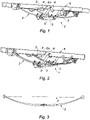
- the dedicated springs 2 can be mounted during step a) on a rear axle 5.
- the dedicated springs 2 can be mounted on a strut, the strut being fixed to a knuckle carrier.
- the dedicated springs 2 are mounted during step a) on the chassis 6 of the vehicle.
- Step a) is advantageously carried out so that the stiffness of each dedicated spring 2 is between 60% and 80% of the original stiffness.
- the original stiffness can be between 90 N/m and 100 N/m, and step a) is advantageously carried out so that the stiffness of each dedicated spring 2 is between 54 N/m and 80 N/m , preferably between 63 N/m and 70 N/m.
- Step a) is advantageously performed so that the deflection F of each dedicated spring 2 is between 106% and 147% of the original deflection.
- step a) is advantageously executed so that the deflection F of each dedicated spring 2 is between 170 mm and 190 mm.
- Such an arrow F of each dedicated spring 2 makes it possible to adapt the attitude of the vehicle according to its end use. The body of the vehicle will not be too high when empty, nor too low when loaded.
- step a) is advantageously executed so that the deflection F of each dedicated spring 2 is between 190 mm and 210 mm.
- Such an arrow F of each dedicated spring 2 makes it possible to adapt the attitude of the vehicle according to its end use. The body of the vehicle will not be too high when empty, nor too low when loaded.
- step a) is advantageously executed so that the deflection F of each dedicated spring 2 is between 200 mm and 220 mm.
- Such an arrow F of each dedicated spring 2 makes it possible to adapt the attitude of the vehicle according to its end use. The body of the vehicle will not be too high when empty, nor too low when loaded.
- each original spring can be of the single-blade type, and step a) is advantageously carried out so that each dedicated spring 2 is of the bi-blade type, as illustrated in figure 2 and 4 .
- each dedicated spring 2 can be of the single-blade type.
- each dedicated spring 2 can also be a spiral (helical) spring.
- the arrow F of the dedicated springs 2 defines a high point and a low point of the suspension of the rear axle 1 of the vehicle.
- the high point can be defined by a shock stop 4, mounted on the chassis 6 of the vehicle (cf. paragraph entitled “Rear suspension obtained” below).
- the dedicated shock absorbers 3 can be mounted during step b) on a rear axle 5.
- the dedicated shock absorbers 3 can be mounted on a strut, the strut being fixed to a knuckle carrier.
- the dedicated shock absorbers 3 are mounted during step b) on the chassis 6 of the vehicle.
- Step b) is advantageously carried out so that each dedicated damper 3 has an open center distance EO, adapted to the deflection F of the dedicated springs 2, so that the dedicated damper 3 can compress freely at the high point and can relax freely at the low point.
- the open center distance EO of each original shock absorber can be between 440 mm and 480 mm
- the open center distance EO of each dedicated shock absorber 3 can be between 470 mm and 510 mm
- the closed center distance of each original shock absorber can be between 300 mm and 320 mm
- the closed center distance of each dedicated shock absorber 3 can be between 310 mm and 330 mm.
- each original shock absorber can be of the twin-tube type, and step b) is advantageously carried out so that each dedicated shock absorber 3 is of the single-tube gas type.
- the gas used is preferably nitrogen.
- Each dedicated damper 3 is preferably of the high pressure gas monotube type, the pressure being able to vary between 12 bars and 25 bars.
- each dedicated damper 3 can be of the twin-tube type.
- Another subject of the invention is a suspension of a rear axle 1 of a vehicle of the ambulance type or of the transport type for persons with reduced mobility, obtained by a process in accordance with the invention.
- the suspension comprises a static phase (i.e. vehicle stationary) where the load of the vehicle is maintained thanks to the dedicated springs 2, which can be leaf(s) or helical.
- the height curve of the vehicle as a function of the load is defined by the stiffness of the blade of the dedicated springs 2 and by the arrow F (empty) of the dedicated springs 2.
- the arrow F of the dedicated springs 2 gives the ordinate to the origin of said height curve while the stiffness of the dedicated springs 2 gives the slope of said curve.
- the height of the laden vehicle corresponds to the so-called “zero” point of the suspension, and makes it possible to define the attitude of the vehicle.
- the suspension includes a dynamic phase (i.e. vehicle in rolling situation) where the irregularities and faults of the road are absorbed by the flexibility of the dedicated springs 2.
- the dedicated springs 2 compress and relax around the zero point of the suspension, and this in order to give clearance to the rear wheels and thereby absorb faults.
- the dedicated dampers 3 make it possible to slow down the movement of the dedicated springs 2 in order to avoid oscillations.
- the dedicated shock absorbers 3 make it possible to define the handling, the dynamism of the vehicle and the comfort felt by the passengers of the vehicle.
- the stroke of the dedicated shock absorbers 3 is delimited by a high point corresponding to the maximum compression point, and by a low point corresponding to the maximum rebound point.
- the high point is preferably defined by a fixed element which can be a shock stop 4.
- the low point is defined by the arrow F (empty) of the dedicated springs 2.
- travel available in compression corresponding to the distance between the high point and zero point.
- travel available in rebound corresponding to the distance between the zero point and the low point.
- the high speed and low speed calibrations carried out during step b) make it possible to modify the damping force of the dedicated shock absorbers 3 according to the nature of the road faults.
- the high speed and low speed calibrations carried out during step b) are intended to find a compromise between comfort, road holding and dynamism of the vehicle.
- the force necessary to compress the dedicated springs 2 is directly linked to their stiffness. The greater the stiffness, the more force will be required to compress the dedicated spring 2, and the greater the shock transcribed to the passengers will be.
- the stiffness of the dedicated springs 2 is strictly less than the original stiffness in order to reduce the force necessary to compress the dedicated springs 2, and thereby improve the filtration of road faults.
- the suspension obtained by a method according to the invention makes it possible to limit the accelerations undergone by the passengers to approximately below the value of 2g, whereas the original suspension can reach 3g or even 4g where the shocks are potentially harsh and can cause harm back.
Landscapes
- Engineering & Computer Science (AREA)
- Mechanical Engineering (AREA)
- Vehicle Body Suspensions (AREA)
- Springs (AREA)
Claims (15)
- Verfahren zur Optimierung einer Aufhängung einer Hinterachse (1) eines Fahrzeugs des Typs Krankenwagen oder des Typs Transportfahrzeug für Personen mit eingeschränkter Mobilität, wobei die Aufhängung Folgendes umfasst:- zwei Ursprungsfedern, die jeweils eine Ursprungssteifigkeit und eine Ursprungsdurchbiegung aufweisen;- zwei Ursprungsstoßdämpfer, die jeweils Folgendes aufweisen:eine Ursprungszugkraft bei geringer Geschwindigkeit für eine Ausfedergeschwindigkeit des Ursprungsstoßdämpfers von weniger als 0,1 m.s-1,eine Ursprungsdruckkraft bei geringer Geschwindigkeit für eine Ausfedergeschwindigkeit des Ursprungsstoßdämpfers von weniger als 0,1 m.s-1,dadurch gekennzeichnet, dass das Verfahren die folgenden Schritte aufweist:a) Ersetzen der beiden Ursprungsfedern durch zwei Spezialfedern (2), die jeweils eine Steifigkeit aufweisen, die strikt unter der Ursprungssteifigkeit liegt, und eine Durchbiegung (F), die strikt über der Ursprungsdurchbiegung liegt;b) Ersetzen der beiden Ursprungsstoßdämpfer durch zwei Spezialstoßdämpfer (3), die jeweils Folgendes aufweisen:- eine Zugkraft bei geringer Geschwindigkeit, für eine Ausfedergeschwindigkeit des Spezialstoßdämpfers (3) von weniger als 0,1 m.s-1, die strikt unter der Ursprungszugkraft bei geringer Geschwindigkeit liegt;- eine Druckkraft bei geringer Geschwindigkeit, für eine Ausfedergeschwindigkeit des Spezialstoßdämpfers (3) von weniger als 0,1 m.s-1, die strikt über der Ursprungsdruckkraft bei geringer Geschwindigkeit liegt.
- Verfahren nach Anspruch 1, wobei jeder Ursprungsstoßdämpfer Folgendes aufweist:- eine Ursprungszugkraft bei hoher Geschwindigkeit für eine Ausfedergeschwindigkeit des Ursprungsstoßdämpfers von mehr als 0,4 m.s-1;- eine Ursprungsdruckkraft bei hoher Geschwindigkeit für eine Ausfedergeschwindigkeit des Ursprungsstoßdämpfers von mehr als 0,4 m.s-1;und wobei der Schritt b) so ausgeführt wird, dass jeder Spezialstoßdämpfer (3) Folgendes aufweist:- eine Zugkraft bei hoher Geschwindigkeit für eine Ausfedergeschwindigkeit des Spezialstoßdämpfers (3) von mehr als 0,4 m.s-1, die strikt unter der Ursprungszugkraft bei hoher Geschwindigkeit liegt;- eine Druckkraft bei hoher Geschwindigkeit für eine Ausfedergeschwindigkeit des Spezialstoßdämpfers (3) von mehr als 0,4 m.s-1, die strikt über der Ursprungsdruckkraft bei hoher Geschwindigkeit liegt.
- Verfahren nach Anspruch 2, wobei der Schritt b) so ausgeführt wird, dass:- die Zugkraft bei hoher Geschwindigkeit jedes Spezialstoßdämpfers (3) zwischen 40 % und 60 %, vorzugsweise zwischen 45 % und 55 %, der Ursprungszugkraft bei hoher Geschwindigkeit liegt;- die Druckkraft bei hoher Geschwindigkeit jedes Spezialstoßdämpfers (3) zwischen 180 % und 220 %, vorzugsweise zwischen 190 % und 210 %, der Ursprungsdruckkraft bei hoher Geschwindigkeit liegt.
- Verfahren nach Anspruch 2 oder 3, wobei die Ursprungszugkraft bei hoher Geschwindigkeit zwischen 1.300 N und 1.400 N liegt, die Ursprungsdruckkraft bei hoher Geschwindigkeit zwischen 140 N und 160 N liegt und der Schritt b) so ausgeführt wird, dass:- die Zugkraft bei hoher Geschwindigkeit jedes Spezialstoßdämpfers (3) zwischen 520 N und 840 N, vorzugsweise zwischen 585 N und 770 N, liegt;- die Druckkraft bei hoher Geschwindigkeit jedes Spezialstoßdämpfers (3) zwischen 252 N und 352 N, vorzugsweise zwischen 266 N und 336 N, liegt.
- Verfahren nach einem der Ansprüche 1 bis 4, wobei der Schritt b) so ausgeführt wird, dass:- die Zugkraft bei geringer Geschwindigkeit jedes Spezialstoßdämpfers (3) zwischen 20 % und 40 %, vorzugsweise zwischen 25 % und 35 %, der Ursprungszugkraft bei geringer Geschwindigkeit liegt;- die Druckkraft bei geringer Geschwindigkeit jedes Spezialstoßdämpfers (3) zwischen 120 % und 160 %, vorzugsweise zwischen 130 % und 150 %, der Ursprungsdruckkraft bei geringer Geschwindigkeit liegt.
- Verfahren nach einem der Ansprüche 1 bis 5, wobei die Ursprungszugkraft bei geringer Geschwindigkeit zwischen 900 N und 1.100 N liegt, die Ursprungsdruckkraft bei geringer Geschwindigkeit zwischen 90 N und 110 N liegt und der Schritt b) so ausgeführt wird, dass:- die Zugkraft bei geringer Geschwindigkeit jedes Spezialstoßdämpfers (3) zwischen 180 N und 440 N, vorzugsweise zwischen 225 N und 385 N, liegt;- die Druckkraft bei geringer Geschwindigkeit jedes Spezialstoßdämpfers (3) zwischen 108 N und 176 N, vorzugsweise zwischen 117 N und 165 N, liegt.
- Verfahren nach einem der Ansprüche 1 bis 6, wobei der Schritt a) so ausgeführt wird, dass die Steifigkeit jeder Spezialfeder (2) zwischen 60 % und 80 % der Ursprungssteifigkeit liegt.
- Verfahren nach einem der Ansprüche 1 bis 7, wobei die Ursprungssteifigkeit zwischen 90 N/m und 100 N/m liegt und der Schritt a) so ausgeführt wird, dass die Steifigkeit jeder Spezialfeder (2) zwischen 54 N/m und 80 N/m, vorzugsweise zwischen 63 N/m und 70 N/m, liegt.
- Verfahren nach einem der Ansprüche 1 bis 8, wobei der Schritt a) so ausgeführt wird, dass die Durchbiegung (F) jeder Spezialfeder (2) zwischen 106 % und 147 % der Ursprungsdurchbiegung liegt.
- Verfahren nach einem der Ansprüche 1 bis 9, wobei das Fahrzeug eine unter den Rädern der Hinterachse (1) gemessene maximale Betriebslastmasse zwischen 1.300 kg und 1.500 kg aufweist, die Ursprungsdurchbiegung zwischen 150 mm und 160 mm liegt und der Schritt a) so ausgeführt wird, dass die Durchbiegung (F) jeder Spezialfeder (2) zwischen 170 mm und 190 mm liegt.
- Verfahren nach einem der Ansprüche 1 bis 9, wobei das Fahrzeug eine unter den Rädern der Hinterachse (1) gemessene maximale Betriebslastmasse zwischen 1.700 kg und 1.800 kg aufweist, die Ursprungsdurchbiegung zwischen 150 mm und 160 mm liegt und der Schritt a) so ausgeführt wird, dass die Durchbiegung (F) jeder Spezialfeder (2) zwischen 190 mm und 210 mm liegt.
- Verfahren nach einem der Ansprüche 1 bis 9, wobei das Fahrzeug eine unter den Rädern der Hinterachse (1) gemessene maximale Betriebslastmasse zwischen 1.800 kg und 2.100 kg aufweist, die Ursprungsdurchbiegung zwischen 150 mm und 160 mm liegt und der Schritt a) so ausgeführt wird, dass die Durchbiegung (F) jeder Spezialfeder (2) zwischen 200 mm und 220 mm liegt.
- Verfahren nach einem der Ansprüche 1 bis 12, wobei jede Ursprungsfeder von einlagiger Art ist und der Schritt a) so ausgeführt wird, dass jede Spezialfeder (2) von zweilagiger Art ist.
- Verfahren nach einem der Ansprüche 1 bis 13, wobei jeder Ursprungsstoßdämpfer von zweirohriger Art ist und der Schritt b) so ausgeführt wird, dass jeder Spezialstoßdämpfer (3) von der Art eines einrohrigen Gasstoßdämpfers ist.
- Verfahren nach einem der Ansprüche 1 bis 14, wobei die Durchbiegung (F) der Spezialfedern (2) einen oberen Punkt und einen unteren Punkt der Aufhängung der Hinterachse (1) des Fahrzeugs definiert und wobei der Schritt b) so ausgeführt wird, dass jeder Spezialstoßdämpfer (3) einen offenen Achsabstand (EO) aufweist, der an die Durchbiegung (F) der Spezialfedern (2) angepasst ist, so dass sich der Spezialstoßdämpfer (3) am oberen Punkt frei einfedern und am unteren Punkt frei ausfedern kann.
Applications Claiming Priority (1)
| Application Number | Priority Date | Filing Date | Title |
|---|---|---|---|
| FR1902396A FR3093424B1 (fr) | 2019-03-08 | 2019-03-08 | Procédé d’optimisation d’une suspension d’un train arrière d’un véhicule de type ambulance ou de type transport de personnes à mobilité réduite |
Publications (2)
| Publication Number | Publication Date |
|---|---|
| EP3705320A1 EP3705320A1 (de) | 2020-09-09 |
| EP3705320B1 true EP3705320B1 (de) | 2022-12-21 |
Family
ID=67441337
Family Applications (1)
| Application Number | Title | Priority Date | Filing Date |
|---|---|---|---|
| EP20159384.5A Active EP3705320B1 (de) | 2019-03-08 | 2020-02-25 | Optimierungsverfahren einer aufhängung einer hinterachse eines fahrzeugs vom typ krankenwagen oder transportfahrzeug für personen mit eingeschränkter mobilität |
Country Status (4)
| Country | Link |
|---|---|
| EP (1) | EP3705320B1 (de) |
| ES (1) | ES2939893T3 (de) |
| FR (1) | FR3093424B1 (de) |
| PT (1) | PT3705320T (de) |
Cited By (1)
| Publication number | Priority date | Publication date | Assignee | Title |
|---|---|---|---|---|
| FR3145700A1 (fr) * | 2023-02-14 | 2024-08-16 | Jsa | Suspension améliorée d’un véhicule |
Families Citing this family (2)
| Publication number | Priority date | Publication date | Assignee | Title |
|---|---|---|---|---|
| FR3116235B1 (fr) * | 2020-11-18 | 2023-06-09 | Jsa | Procédé d’optimisation d’une suspension d’un train arrière d’un véhicule automobile |
| FR3139756A1 (fr) * | 2022-09-19 | 2024-03-22 | Jsa | Procédé d’optimisation d’au moins une suspension d’un véhicule automoteur spécialisé |
Family Cites Families (1)
| Publication number | Priority date | Publication date | Assignee | Title |
|---|---|---|---|---|
| DE19820277C1 (de) * | 1998-05-07 | 1999-07-22 | Eras Entwicklung Und Realisati | Schwingungsisolationsvorrichtung für Fahrzeuge, insbesondere Krankentransportfahrzeuge |
-
2019
- 2019-03-08 FR FR1902396A patent/FR3093424B1/fr not_active Expired - Fee Related
-
2020
- 2020-02-25 PT PT201593845T patent/PT3705320T/pt unknown
- 2020-02-25 EP EP20159384.5A patent/EP3705320B1/de active Active
- 2020-02-25 ES ES20159384T patent/ES2939893T3/es active Active
Cited By (1)
| Publication number | Priority date | Publication date | Assignee | Title |
|---|---|---|---|---|
| FR3145700A1 (fr) * | 2023-02-14 | 2024-08-16 | Jsa | Suspension améliorée d’un véhicule |
Also Published As
| Publication number | Publication date |
|---|---|
| FR3093424A1 (fr) | 2020-09-11 |
| PT3705320T (pt) | 2023-03-03 |
| ES2939893T3 (es) | 2023-04-27 |
| FR3093424B1 (fr) | 2021-02-19 |
| EP3705320A1 (de) | 2020-09-09 |
Similar Documents
| Publication | Publication Date | Title |
|---|---|---|
| EP3705320B1 (de) | Optimierungsverfahren einer aufhängung einer hinterachse eines fahrzeugs vom typ krankenwagen oder transportfahrzeug für personen mit eingeschränkter mobilität | |
| EP0446338B1 (de) | Verfahren zur aufhängung eines fahrzeugrads | |
| EP0003458B1 (de) | Dämpfer für ein Fahrzeug mit elastischer Aufhängung | |
| EP0520928A1 (de) | Fahrzeugaufhängung, bei der zwei Steifigkeiten benutzt werden, eine für ein gutes Niveau des Komforts und die andere für ein gutes Niveau des Fahrzeugverhaltens | |
| KR20170140286A (ko) | 조합 스프링 보상 서스펜션 장치 | |
| WO2015005841A1 (en) | Vehicle suspension and leaf spring therefore | |
| FR2757107A1 (fr) | Suspensions de roue de vehicule utilisant un ressort combine a une armature souple destinee a modifier sa courbe de raideur | |
| CA2956917A1 (fr) | Atterrisseur pour aeronef comportant un amortisseur principal et un amortisseur secondaire anti shimmy | |
| JPS6042044B2 (ja) | スタビライザ−取付装置 | |
| FR3073174B1 (fr) | Amortisseur hydraulique de suspension de vehicule avec colonne a inertie | |
| EP0439401B1 (de) | Scherenstromabnehmer mit gedämpfter Kopfaufhängung | |
| FR3095159A1 (fr) | Procédé de renforcement d’une suspension d’un train d’un véhicule | |
| FR3116235A1 (fr) | Procédé d’optimisation d’une suspension d’un train arrière d’un véhicule automobile | |
| FR3139756A1 (fr) | Procédé d’optimisation d’au moins une suspension d’un véhicule automoteur spécialisé | |
| EP4691807A1 (de) | Verfahren zur optimierung der verstärkung mindestens einer aufhängung eines nutzfahrzeugs | |
| WO2004048136A1 (fr) | Methode et systeme pour l´extension de la mobilite d´un vehicule | |
| FR2894184A1 (fr) | Dispositif formant butee de detente d'une suspension d'un vehicule notamment automobile | |
| FR3100854A1 (fr) | Amortisseur inertiel pour vehicule automobile | |
| CH631122A5 (fr) | Suspension de vehicule. | |
| FR3145700A1 (fr) | Suspension améliorée d’un véhicule | |
| FR3049502A1 (fr) | Vehicule a systeme de suspension hydraulique | |
| FR3134154A1 (fr) | Vehicule automobile comprenant un amortisseur de fin de course optimise | |
| RU2048303C1 (ru) | Подвеска транспортного средства | |
| FR3049501A1 (fr) | Vehicule a systeme de suspension hydraulique | |
| FR2593256A1 (fr) | Amortisseur pour suspension de vehicule automobile |
Legal Events
| Date | Code | Title | Description |
|---|---|---|---|
| PUAI | Public reference made under article 153(3) epc to a published international application that has entered the european phase |
Free format text: ORIGINAL CODE: 0009012 |
|
| STAA | Information on the status of an ep patent application or granted ep patent |
Free format text: STATUS: REQUEST FOR EXAMINATION WAS MADE |
|
| 17P | Request for examination filed |
Effective date: 20200225 |
|
| AK | Designated contracting states |
Kind code of ref document: A1 Designated state(s): AL AT BE BG CH CY CZ DE DK EE ES FI FR GB GR HR HU IE IS IT LI LT LU LV MC MK MT NL NO PL PT RO RS SE SI SK SM TR |
|
| AX | Request for extension of the european patent |
Extension state: BA ME |
|
| GRAP | Despatch of communication of intention to grant a patent |
Free format text: ORIGINAL CODE: EPIDOSNIGR1 |
|
| STAA | Information on the status of an ep patent application or granted ep patent |
Free format text: STATUS: GRANT OF PATENT IS INTENDED |
|
| INTG | Intention to grant announced |
Effective date: 20220714 |
|
| GRAS | Grant fee paid |
Free format text: ORIGINAL CODE: EPIDOSNIGR3 |
|
| GRAA | (expected) grant |
Free format text: ORIGINAL CODE: 0009210 |
|
| STAA | Information on the status of an ep patent application or granted ep patent |
Free format text: STATUS: THE PATENT HAS BEEN GRANTED |
|
| AK | Designated contracting states |
Kind code of ref document: B1 Designated state(s): AL AT BE BG CH CY CZ DE DK EE ES FI FR GB GR HR HU IE IS IT LI LT LU LV MC MK MT NL NO PL PT RO RS SE SI SK SM TR |
|
| REG | Reference to a national code |
Ref country code: GB Ref legal event code: FG4D Free format text: NOT ENGLISH |
|
| REG | Reference to a national code |
Ref country code: DE Ref legal event code: R096 Ref document number: 602020006987 Country of ref document: DE |
|
| REG | Reference to a national code |
Ref country code: CH Ref legal event code: EP |
|
| REG | Reference to a national code |
Ref country code: AT Ref legal event code: REF Ref document number: 1538849 Country of ref document: AT Kind code of ref document: T Effective date: 20230115 |
|
| REG | Reference to a national code |
Ref country code: IE Ref legal event code: FG4D Free format text: LANGUAGE OF EP DOCUMENT: FRENCH |
|
| REG | Reference to a national code |
Ref country code: PT Ref legal event code: SC4A Ref document number: 3705320 Country of ref document: PT Date of ref document: 20230303 Kind code of ref document: T Free format text: AVAILABILITY OF NATIONAL TRANSLATION Effective date: 20230227 |
|
| REG | Reference to a national code |
Ref country code: LT Ref legal event code: MG9D |
|
| REG | Reference to a national code |
Ref country code: NL Ref legal event code: MP Effective date: 20221221 |
|
| REG | Reference to a national code |
Ref country code: ES Ref legal event code: FG2A Ref document number: 2939893 Country of ref document: ES Kind code of ref document: T3 Effective date: 20230427 |
|
| PG25 | Lapsed in a contracting state [announced via postgrant information from national office to epo] |
Ref country code: SE Free format text: LAPSE BECAUSE OF FAILURE TO SUBMIT A TRANSLATION OF THE DESCRIPTION OR TO PAY THE FEE WITHIN THE PRESCRIBED TIME-LIMIT Effective date: 20221221 Ref country code: NO Free format text: LAPSE BECAUSE OF FAILURE TO SUBMIT A TRANSLATION OF THE DESCRIPTION OR TO PAY THE FEE WITHIN THE PRESCRIBED TIME-LIMIT Effective date: 20230321 Ref country code: LT Free format text: LAPSE BECAUSE OF FAILURE TO SUBMIT A TRANSLATION OF THE DESCRIPTION OR TO PAY THE FEE WITHIN THE PRESCRIBED TIME-LIMIT Effective date: 20221221 Ref country code: FI Free format text: LAPSE BECAUSE OF FAILURE TO SUBMIT A TRANSLATION OF THE DESCRIPTION OR TO PAY THE FEE WITHIN THE PRESCRIBED TIME-LIMIT Effective date: 20221221 |
|
| REG | Reference to a national code |
Ref country code: AT Ref legal event code: MK05 Ref document number: 1538849 Country of ref document: AT Kind code of ref document: T Effective date: 20221221 |
|
| PG25 | Lapsed in a contracting state [announced via postgrant information from national office to epo] |
Ref country code: RS Free format text: LAPSE BECAUSE OF FAILURE TO SUBMIT A TRANSLATION OF THE DESCRIPTION OR TO PAY THE FEE WITHIN THE PRESCRIBED TIME-LIMIT Effective date: 20221221 Ref country code: LV Free format text: LAPSE BECAUSE OF FAILURE TO SUBMIT A TRANSLATION OF THE DESCRIPTION OR TO PAY THE FEE WITHIN THE PRESCRIBED TIME-LIMIT Effective date: 20221221 Ref country code: HR Free format text: LAPSE BECAUSE OF FAILURE TO SUBMIT A TRANSLATION OF THE DESCRIPTION OR TO PAY THE FEE WITHIN THE PRESCRIBED TIME-LIMIT Effective date: 20221221 Ref country code: GR Free format text: LAPSE BECAUSE OF FAILURE TO SUBMIT A TRANSLATION OF THE DESCRIPTION OR TO PAY THE FEE WITHIN THE PRESCRIBED TIME-LIMIT Effective date: 20230322 |
|
| PG25 | Lapsed in a contracting state [announced via postgrant information from national office to epo] |
Ref country code: NL Free format text: LAPSE BECAUSE OF FAILURE TO SUBMIT A TRANSLATION OF THE DESCRIPTION OR TO PAY THE FEE WITHIN THE PRESCRIBED TIME-LIMIT Effective date: 20221221 |
|
| PG25 | Lapsed in a contracting state [announced via postgrant information from national office to epo] |
Ref country code: SM Free format text: LAPSE BECAUSE OF FAILURE TO SUBMIT A TRANSLATION OF THE DESCRIPTION OR TO PAY THE FEE WITHIN THE PRESCRIBED TIME-LIMIT Effective date: 20221221 Ref country code: RO Free format text: LAPSE BECAUSE OF FAILURE TO SUBMIT A TRANSLATION OF THE DESCRIPTION OR TO PAY THE FEE WITHIN THE PRESCRIBED TIME-LIMIT Effective date: 20221221 Ref country code: EE Free format text: LAPSE BECAUSE OF FAILURE TO SUBMIT A TRANSLATION OF THE DESCRIPTION OR TO PAY THE FEE WITHIN THE PRESCRIBED TIME-LIMIT Effective date: 20221221 Ref country code: CZ Free format text: LAPSE BECAUSE OF FAILURE TO SUBMIT A TRANSLATION OF THE DESCRIPTION OR TO PAY THE FEE WITHIN THE PRESCRIBED TIME-LIMIT Effective date: 20221221 Ref country code: AT Free format text: LAPSE BECAUSE OF FAILURE TO SUBMIT A TRANSLATION OF THE DESCRIPTION OR TO PAY THE FEE WITHIN THE PRESCRIBED TIME-LIMIT Effective date: 20221221 |
|
| PG25 | Lapsed in a contracting state [announced via postgrant information from national office to epo] |
Ref country code: SK Free format text: LAPSE BECAUSE OF FAILURE TO SUBMIT A TRANSLATION OF THE DESCRIPTION OR TO PAY THE FEE WITHIN THE PRESCRIBED TIME-LIMIT Effective date: 20221221 Ref country code: PL Free format text: LAPSE BECAUSE OF FAILURE TO SUBMIT A TRANSLATION OF THE DESCRIPTION OR TO PAY THE FEE WITHIN THE PRESCRIBED TIME-LIMIT Effective date: 20221221 Ref country code: IS Free format text: LAPSE BECAUSE OF FAILURE TO SUBMIT A TRANSLATION OF THE DESCRIPTION OR TO PAY THE FEE WITHIN THE PRESCRIBED TIME-LIMIT Effective date: 20230421 Ref country code: AL Free format text: LAPSE BECAUSE OF FAILURE TO SUBMIT A TRANSLATION OF THE DESCRIPTION OR TO PAY THE FEE WITHIN THE PRESCRIBED TIME-LIMIT Effective date: 20221221 |
|
| REG | Reference to a national code |
Ref country code: DE Ref legal event code: R097 Ref document number: 602020006987 Country of ref document: DE |
|
| PG25 | Lapsed in a contracting state [announced via postgrant information from national office to epo] |
Ref country code: MC Free format text: LAPSE BECAUSE OF FAILURE TO SUBMIT A TRANSLATION OF THE DESCRIPTION OR TO PAY THE FEE WITHIN THE PRESCRIBED TIME-LIMIT Effective date: 20221221 |
|
| REG | Reference to a national code |
Ref country code: CH Ref legal event code: PL |
|
| REG | Reference to a national code |
Ref country code: BE Ref legal event code: MM Effective date: 20230228 |
|
| PLBE | No opposition filed within time limit |
Free format text: ORIGINAL CODE: 0009261 |
|
| STAA | Information on the status of an ep patent application or granted ep patent |
Free format text: STATUS: NO OPPOSITION FILED WITHIN TIME LIMIT |
|
| PG25 | Lapsed in a contracting state [announced via postgrant information from national office to epo] |
Ref country code: LU Free format text: LAPSE BECAUSE OF NON-PAYMENT OF DUE FEES Effective date: 20230225 Ref country code: LI Free format text: LAPSE BECAUSE OF NON-PAYMENT OF DUE FEES Effective date: 20230228 Ref country code: DK Free format text: LAPSE BECAUSE OF FAILURE TO SUBMIT A TRANSLATION OF THE DESCRIPTION OR TO PAY THE FEE WITHIN THE PRESCRIBED TIME-LIMIT Effective date: 20221221 Ref country code: CH Free format text: LAPSE BECAUSE OF NON-PAYMENT OF DUE FEES Effective date: 20230228 |
|
| 26N | No opposition filed |
Effective date: 20230922 |
|
| REG | Reference to a national code |
Ref country code: IE Ref legal event code: MM4A |
|
| PG25 | Lapsed in a contracting state [announced via postgrant information from national office to epo] |
Ref country code: SI Free format text: LAPSE BECAUSE OF FAILURE TO SUBMIT A TRANSLATION OF THE DESCRIPTION OR TO PAY THE FEE WITHIN THE PRESCRIBED TIME-LIMIT Effective date: 20221221 Ref country code: IE Free format text: LAPSE BECAUSE OF NON-PAYMENT OF DUE FEES Effective date: 20230225 |
|
| PG25 | Lapsed in a contracting state [announced via postgrant information from national office to epo] |
Ref country code: BE Free format text: LAPSE BECAUSE OF NON-PAYMENT OF DUE FEES Effective date: 20230228 |
|
| PG25 | Lapsed in a contracting state [announced via postgrant information from national office to epo] |
Ref country code: BG Free format text: LAPSE BECAUSE OF FAILURE TO SUBMIT A TRANSLATION OF THE DESCRIPTION OR TO PAY THE FEE WITHIN THE PRESCRIBED TIME-LIMIT Effective date: 20221221 |
|
| PG25 | Lapsed in a contracting state [announced via postgrant information from national office to epo] |
Ref country code: BG Free format text: LAPSE BECAUSE OF FAILURE TO SUBMIT A TRANSLATION OF THE DESCRIPTION OR TO PAY THE FEE WITHIN THE PRESCRIBED TIME-LIMIT Effective date: 20221221 |
|
| PGFP | Annual fee paid to national office [announced via postgrant information from national office to epo] |
Ref country code: DE Payment date: 20250225 Year of fee payment: 6 |
|
| PGFP | Annual fee paid to national office [announced via postgrant information from national office to epo] |
Ref country code: ES Payment date: 20250303 Year of fee payment: 6 |
|
| PGFP | Annual fee paid to national office [announced via postgrant information from national office to epo] |
Ref country code: IT Payment date: 20250226 Year of fee payment: 6 |
|
| PG25 | Lapsed in a contracting state [announced via postgrant information from national office to epo] |
Ref country code: CY Free format text: LAPSE BECAUSE OF FAILURE TO SUBMIT A TRANSLATION OF THE DESCRIPTION OR TO PAY THE FEE WITHIN THE PRESCRIBED TIME-LIMIT; INVALID AB INITIO Effective date: 20200225 |
|
| PG25 | Lapsed in a contracting state [announced via postgrant information from national office to epo] |
Ref country code: HU Free format text: LAPSE BECAUSE OF FAILURE TO SUBMIT A TRANSLATION OF THE DESCRIPTION OR TO PAY THE FEE WITHIN THE PRESCRIBED TIME-LIMIT; INVALID AB INITIO Effective date: 20200225 |
|
| PG25 | Lapsed in a contracting state [announced via postgrant information from national office to epo] |
Ref country code: TR Free format text: LAPSE BECAUSE OF FAILURE TO SUBMIT A TRANSLATION OF THE DESCRIPTION OR TO PAY THE FEE WITHIN THE PRESCRIBED TIME-LIMIT Effective date: 20221221 |
|
| PGFP | Annual fee paid to national office [announced via postgrant information from national office to epo] |
Ref country code: GB Payment date: 20260320 Year of fee payment: 7 |
|
| PGFP | Annual fee paid to national office [announced via postgrant information from national office to epo] |
Ref country code: FR Payment date: 20260320 Year of fee payment: 7 |
|
| PGFP | Annual fee paid to national office [announced via postgrant information from national office to epo] |
Ref country code: PT Payment date: 20260326 Year of fee payment: 7 |