EP3705227A2 - Abstützung einer konturierten materialbahn bei bearbeitungsvorgängen - Google Patents
Abstützung einer konturierten materialbahn bei bearbeitungsvorgängen Download PDFInfo
- Publication number
- EP3705227A2 EP3705227A2 EP20151881.8A EP20151881A EP3705227A2 EP 3705227 A2 EP3705227 A2 EP 3705227A2 EP 20151881 A EP20151881 A EP 20151881A EP 3705227 A2 EP3705227 A2 EP 3705227A2
- Authority
- EP
- European Patent Office
- Prior art keywords
- sheet
- machining
- support
- vacuum
- support surface
- Prior art date
- Legal status (The legal status is an assumption and is not a legal conclusion. Google has not performed a legal analysis and makes no representation as to the accuracy of the status listed.)
- Granted
Links
Images




Classifications
-
- B—PERFORMING OPERATIONS; TRANSPORTING
- B23—MACHINE TOOLS; METAL-WORKING NOT OTHERWISE PROVIDED FOR
- B23Q—DETAILS, COMPONENTS, OR ACCESSORIES FOR MACHINE TOOLS, e.g. ARRANGEMENTS FOR COPYING OR CONTROLLING; MACHINE TOOLS IN GENERAL CHARACTERISED BY THE CONSTRUCTION OF PARTICULAR DETAILS OR COMPONENTS; COMBINATIONS OR ASSOCIATIONS OF METAL-WORKING MACHINES, NOT DIRECTED TO A PARTICULAR RESULT
- B23Q3/00—Devices holding, supporting, or positioning work or tools, of a kind normally removable from the machine
- B23Q3/02—Devices holding, supporting, or positioning work or tools, of a kind normally removable from the machine for mounting on a work-table, tool-slide, or analogous part
- B23Q3/06—Work-clamping means
- B23Q3/062—Work-clamping means adapted for holding workpieces having a special form or being made from a special material
- B23Q3/065—Work-clamping means adapted for holding workpieces having a special form or being made from a special material for holding workpieces being specially deformable, e.g. made from thin-walled or elastic material
-
- B—PERFORMING OPERATIONS; TRANSPORTING
- B25—HAND TOOLS; PORTABLE POWER-DRIVEN TOOLS; MANIPULATORS
- B25B—TOOLS OR BENCH DEVICES NOT OTHERWISE PROVIDED FOR, FOR FASTENING, CONNECTING, DISENGAGING, OR HOLDING
- B25B11/00—Work holders not covered by any preceding group in the subclass, e.g. magnetic work holders, vacuum work holders
- B25B11/005—Vacuum work holders
-
- B—PERFORMING OPERATIONS; TRANSPORTING
- B23—MACHINE TOOLS; METAL-WORKING NOT OTHERWISE PROVIDED FOR
- B23Q—DETAILS, COMPONENTS, OR ACCESSORIES FOR MACHINE TOOLS, e.g. ARRANGEMENTS FOR COPYING OR CONTROLLING; MACHINE TOOLS IN GENERAL CHARACTERISED BY THE CONSTRUCTION OF PARTICULAR DETAILS OR COMPONENTS; COMBINATIONS OR ASSOCIATIONS OF METAL-WORKING MACHINES, NOT DIRECTED TO A PARTICULAR RESULT
- B23Q3/00—Devices holding, supporting, or positioning work or tools, of a kind normally removable from the machine
- B23Q3/02—Devices holding, supporting, or positioning work or tools, of a kind normally removable from the machine for mounting on a work-table, tool-slide, or analogous part
- B23Q3/06—Work-clamping means
- B23Q3/08—Work-clamping means other than mechanically-actuated
- B23Q3/088—Work-clamping means other than mechanically-actuated using vacuum means
-
- B—PERFORMING OPERATIONS; TRANSPORTING
- B23—MACHINE TOOLS; METAL-WORKING NOT OTHERWISE PROVIDED FOR
- B23B—TURNING; BORING
- B23B47/00—Constructional features of components specially designed for boring or drilling machines; Accessories therefor
- B23B47/28—Drill jigs for workpieces
- B23B47/287—Jigs for drilling plate-like workpieces
-
- H—ELECTRICITY
- H10—SEMICONDUCTOR DEVICES; ELECTRIC SOLID-STATE DEVICES NOT OTHERWISE PROVIDED FOR
- H10P—GENERIC PROCESSES OR APPARATUS FOR THE MANUFACTURE OR TREATMENT OF DEVICES COVERED BY CLASS H10
- H10P72/00—Handling or holding of wafers, substrates or devices during manufacture or treatment thereof
- H10P72/70—Handling or holding of wafers, substrates or devices during manufacture or treatment thereof for supporting or gripping
- H10P72/78—Handling or holding of wafers, substrates or devices during manufacture or treatment thereof for supporting or gripping using vacuum or suction, e.g. Bernoulli chucks
-
- B—PERFORMING OPERATIONS; TRANSPORTING
- B23—MACHINE TOOLS; METAL-WORKING NOT OTHERWISE PROVIDED FOR
- B23B—TURNING; BORING
- B23B2215/00—Details of workpieces
- B23B2215/04—Aircraft components
-
- B—PERFORMING OPERATIONS; TRANSPORTING
- B23—MACHINE TOOLS; METAL-WORKING NOT OTHERWISE PROVIDED FOR
- B23B—TURNING; BORING
- B23B2270/00—Details of turning, boring or drilling machines, processes or tools not otherwise provided for
- B23B2270/62—Use of suction
Definitions
- the present disclosure relates generally to machining operations on sheets, and more specifically to supporting a sheet of material during machining operations.
- machining operations such as drilling or milling may be performed on a pre-formed sheet of material.
- the initial machining force from the drill bit on an unsupported portion of a sheet and the resulting spring back of the sheet may result in less than desired hole quality.
- the initial machining force from the drill bit and the resulting spring back of the sheet can undesirably affect the drill bit, including potentially breaking the drill bit.
- An illustrative embodiment of the present disclosure provides a method of reducing spring back of a sheet following a machining operation on the sheet.
- a vacuum is drawn across a porous material of a machining support to hold a second surface of the sheet against a support surface of the machining support, the porous material of the machining support sealed on each surface except the support surface.
- the vacuum is maintained within the porous material while performing the machining operation through a first surface of the sheet opposite the second surface.
- Another illustrative embodiment of the present disclosure provides a method of reducing spring back of a sheet following a machining operation on the sheet.
- a second surface of the sheet is placed in contact with a support surface of a machining support, the machining support comprising a porous material sealed on each surface of the machining support except the support surface.
- a vacuum is drawn across the porous material to hold the second surface against the support surface.
- the machining operation is performed through a first surface of the sheet opposite the second surface. The vacuum is maintained within the porous material while performing the machining operation.
- a machining support configured to reduce spring back of a sheet following a machining operation on the sheet.
- the machining support comprises a porous material with a plurality of surfaces including a support surface having a contour configured to contact and support the sheet; sealing material covering each of the plurality of surfaces except the support surface; and a vacuum port configured to provide a vacuum to the porous material.
- a further illustrative embodiment of the present disclosure provides a method of forming a machining support configured to reduce spring back of a sheet following a machining operation on the sheet.
- Porous material is shaped to create a plurality of surfaces including a support surface having a contour configured to contact and support the sheet.
- a sealing material is applied to each of the plurality of surfaces except the support surface.
- the illustrative embodiments recognize and take into account one or more different considerations.
- the illustrative embodiments recognize and take into account that prior to machining the sheet, the sheet is restrained against a backing plate style support tool. Often, the sheet is restrained at the periphery, leaving the remainder of the sheet unrestrained such that the restraint does not inhibit processing. While the periphery of sheet is restrained, the remainder of the sheet may bend such that portions of the sheet are not in contact with the support surface of the support tool. The portions of the sheet not in contact with the support surface are unsupported. While the periphery of the sheet is restrained against the support tool, a machining operation is performed on a portion of the sheet. The portion of the sheet to be machined may not be contacting the support tool and may be unsupported.
- the illustrative embodiments recognize and take into account that performing machining operations on an unsupported portion of the sheet results in spring back.
- the drill bit initially makes contact with the unsupported surface of the sheet and applies pressure to the sheet.
- the pressure, or machining force, applied from the drill bit initially causes the sheet to compress against the support tool prior to penetrating through the sheet. Once the sheet is completely penetrated, the elastic energy causes the sheet to rapidly spring back to its free state. This spring back of the sheet is uncontrolled.
- the sheet is pushed by the machining force of the drill bit in the direction of the support tool during the machining operation. After the drill bit passes through the sheet, the sheet is no longer subjected to the pushing machining force of the drill bit, and the sheet springs back to its original location.
- the illustrative embodiments recognize and take into account that a support tool desirably complements the shape of the sheet.
- a support tool may not precisely complement the shape of the sheet over the entirety of the support tool.
- the support surface of the support tool may be non-planar to support the sheet.
- restraining a sheet on a support tool may result in a gap between the support surface and the sheet.
- the illustrative embodiments recognize and take into account that the support surface of the support tool may be non-planar to support the sheet.
- the illustrative embodiments recognize and take into account that the support surface of the support tool may be concave to support the sheet. When the support surface is concave, restraining the periphery of sheet causes the remainder of the sheet to bend such that portions of the sheet are not in contact with the support surface of the support tool.
- the illustrative embodiments recognize and take into account that a combination of the shape of the sheet and the shape of the support tool may cause gaps between the sheet and the support tool.
- the illustrative embodiments recognize and take into account that a gap may occur even when potential spring back energy is present in the sheet.
- the illustrative embodiments also recognize and take into account that to reduce spring back of a sheet of material, contact between the sheet and the support tool may be increased.
- Spring back of the sheet is the sheet returning to an original shape when force is removed from the sheet.
- spring back of the sheet following the machining operation is reduced or eliminated.
- the sheet substantially maintains its shape before and as a machining force is applied to the sheet.
- spring back of the sheet is constrained until after the machining operations are completed and the sheet is released from the support tool.
- the illustrative embodiments recognize and take into account that performing machining operations on an unsupported portion of the sheet may result in undesirable locations for the machining operations.
- the illustrative embodiments recognize and take into account that it may be desirable for the sheet to contact the support surface for desirable positioning of features created during the machining operations.
- the illustrative embodiments also recognize and take into account that to reduce spring back a sheet of material may be tacked to a support tool using a temporary adhesive.
- adhesive residue may transfer to machining tools, such as drill bits.
- Adhesive residue on machining tools may undesirably affect at least one of the life of the machining tools, or the quality of the manufactured component.
- adhesive residue may undesirably affect the quality of drilled holes in a manufactured component.
- the illustrative embodiments recognize and take into account that applying an adhesive adds time and cost to the manufacturing process.
- an adhesive used to hold a sheet of material to a support tool would be qualified for contact use with the type of material of the sheet as well as the material of the support tool. It would be undesirable to use an adhesive that would damage either the material of the sheet or the material of the support tool. Depending upon the material of the sheet, there may be a limited quantity of qualified adhesives.
- vacuum is applied to a sheet to hold the sheet against a support tool.
- conventional vacuum plates having vacuum channels around the periphery do not apply vacuum to the center of the sheet where machining operations are performed. Machining operations, such as perforating processes, would diminish the effectiveness of conventional vacuum plates with vacuum channels in the region of machining operations.
- conventional methods of attempting to reduce spring back include methods of holding the sheet against the support tool.
- Conventional methods of attempting to reduce spring back include methods of increasing the supported surface of the sheet around the periphery of the sheet.
- the illustrative embodiments provide machining supports and methods for reducing spring back in machining operations.
- the illustrative embodiments support the sheet using machining supports formed of porous material. By holding the sheet against a support surface using vacuum, spring back of the sheet following the machining operation is reduced or eliminated.
- Manufacturing environment 100 has machining support 102 to support sheet 104 while machining operation 106 is performed by machining tool 108 on sheet 104.
- Machining support 102 is configured to reduce spring back of sheet 104 following machining operation 106 is on sheet 104.
- Machining support 102 comprises porous material 110 with plurality of surfaces 112 including support surface 114 having contour 116 configured to contact and support sheet 104, sealing material 118 covering each of plurality of surfaces 112 except support surface 114, and vacuum port 120 configured to provide vacuum 122 to porous material 110.
- Sealing material 118 on exterior surfaces 124 prevents vacuum 122 from escaping through exterior surfaces 124. Vacuum 122 will escape through support surface 114 to hold sheet 104 against support surface 114.
- indentations 126 are present in support surface 114. In these illustrative examples, indentations 126 correspond to locations of machining operations on sheet 104. In these illustrative examples, indentations 126 correspond to locations of number of features 128 of sheet 104. As used herein, a "number of' items is one or more items. Thus, number of features 128 is one or more features. In these illustrative examples, an indentation corresponds to a feature when machining tool 108 could extend through the feature and into the indentation.
- indentations 126 are formed by performing machining operation 106 on sheet 104.
- machining operation 106 is drilling 130 holes 132 in sheet 104
- indentations 126 are formed by drilling 130 extending through sheet 104 and impacting porous material 110.
- each of indentations 126 is larger than a corresponding feature of number of features 128 to be machined into sheet 104.
- machining operation 106 will not remove material from support surface 114.
- machining tolerances are taken into account.
- indentations 126 are formed in support surface 114, sealing material 134 is placed within each of indentations 126.
- indentations 126 are formed and filled with sealing material 134 prior to placing sheet 104 on support surface 114.
- indentations 126 are formed when sheet 104 is on support surface 114 and indentations 126 are sealed with sealing material 134 after sheet 104 is removed from machining support 102.
- Porous material 110 takes any desirable form.
- porous material 110 is an open cell foam.
- porous material 110 is a manufactured wood.
- Porous material 110 is selected to allow vacuum 122 to travel throughout machining support 102 and escape through support surface 114.
- the physical characteristics of porous material 110, including the porosity, act as a distribution system for vacuum 122 throughout porous material 110.
- Machining support 102 is formed of porous material 110 and the porosity of porous material 110 acts as a distribution system for vacuum 122 throughout machining support 102.
- Sheet 104 is supported by support surface 114 while machining operation 106 is performed on sheet 104. Machining operation 106 is used to form number of features 128 in sheet 104.
- Sheet 104 is formed of material 136.
- material 136 takes the form of any desirable material that has elastic deformation 138.
- Elastic deformation 138 is the ability of material 136 to temporarily change shape when a force is applied. When the force is removed, elastic deformation 138 allows material 136 to return to its original shape.
- material 136 is one of metal 140 or composite material 142. When material 136 is composite material 142, composite material 142 is cured or partially cured.
- sheet 104 is referred to as thin sheet 144.
- Sheet 104 may be referred to as thin sheet 144, as sheet 104 is thin enough to deflect when pressure from machining operation 106 is applied to sheet 104 without machining support 102 having support surface 114.
- the thickness of material 136 is between 0.020" and 0.100".
- a quantity of plies and orientation of fibers in composite material 142 affect the deflection of sheet 104.
- Composite materials having the same thickness but different layups may deflect to a different degree.
- Sheet 104 is held against support surface 114 when vacuum 122 is provided to porous material 110 of machining support 102.
- Contour 116 of support surface 114 is configured to support curvature 148.
- Support surface 114 is configured to support all of second surface 150, not just periphery 146.
- Machining operation 106 is performed on sheet 104 to form number of features 128 while sheet 104 is held against support surface 114. Machining operation 106 is performed through first surface 152 of sheet 104. First surface 152 is opposite second surface 150. In some illustrative examples, first surface 152 is referred to as a front surface of sheet 104 and second surface 150 is referred to as a back surface of sheet 104.
- Machining operation 106 is any desirable operation. In some illustrative examples, machining operation 106 is drilling 130. In some illustrative examples, machining operation 106 is routing 154. Machining operation 106 forms number of features 128.
- Number of features 128 may take any desirable form.
- Number of features 128 includes holes 132 or other shapes, such as channels 156 or slots 158.
- number of features 128 are each in the .020" to .300" size range.
- number of features 128 is arranged in a repeating pattern to achieve a consistent percent open area. Open area is a ratio of the amount of first surface 152 taken up by number of features 128.
- the pattern of number of features 128 has a percent open area in the range of five percent open area to 30 percent open area based on design criteria of component 162.
- Number of features 128 is formed in region 160.
- sheet 104 were restrained only by periphery 146, performing machining operation 106 in region 160 would result in spring back.
- spring back of sheet 104 is reduced or eliminated following machining operation 106 in region 160.
- Component 162 is a component of any desirable type of platform.
- the platform may be, for example, a vehicle, a mobile platform, a stationary platform, a land-based structure, an aquatic-based structure, or a space-based structure. More specifically, a platform may be a surface ship, a tank, a personnel carrier, a train, a spacecraft, a space station, a satellite, a submarine, an automobile, a power plant, a bridge, a dam, a house, a manufacturing facility, a building, or other suitable platforms. In some illustrative examples, the platform takes the form of an aircraft. In these illustrative examples, component 162 is aircraft component 164.
- Component 162 has at least one feature formed by machining tool 108 in machining operation 106.
- component 162 may have a plurality of slots, a plurality of channels, a plurality of holes, or any other desired feature.
- component 162 is a perforated component.
- component 162 takes the form of dampener 166. Dampener 166 may be an acoustic dampener, a pressure dampener, or any other type of dampener.
- manufacturing environment 100 and machining support 102 in Figure 1 is not meant to imply physical or architectural limitations to the manner in which an illustrative embodiment may be implemented.
- Other components in addition to or in place of the ones illustrated may be used. Some components may be unnecessary.
- the blocks are presented to illustrate some functional components. One or more of these blocks may be combined, divided, or combined and divided into different blocks when implemented in an illustrative embodiment.
- component 162 is described as a dampener 166, component 162 may take any desirable form.
- component 162 is an aesthetic panel for decorating an interior or an exterior of a platform.
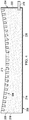
- FIG. 2 an illustration of a cross-sectional view of a sheet on a machining support configured to reduce spring back following machining operations is depicted in accordance with an illustrative embodiment.
- sheet 202 is held against machining support 204.
- Machining support 204 is configured to reduce spring back of sheet 202 following a machining operation on sheet 202.
- Machining support 204 is an implementation of machining support 102 of Figure 1 .
- Machining support 204 comprises porous material 206 with plurality of surfaces 208. Plurality of surfaces 208 includes support surface 210 having contour 212 configured to contact and support sheet 202. Sealing material 214 covers each of plurality of surfaces 208 except support surface 210.
- Vacuum port 216 is configured to provide a vacuum to porous material 206.
- Sealing material 214 prevents a vacuum from escaping through plurality of surfaces 208 other than support surface 210.
- sealing material 214 on exterior surface 218 prevents vacuum from escaping exterior surface 218.
- sealing material 214 on exterior surface 220 prevents vacuum from escaping exterior surface 220.
- Vacuum port 216 extends through sealing material 214 of exterior surface 222.
- Porous material 206 takes any desirable form to transport vacuum throughout machining support 204.
- porous material 206 is an open cell foam.
- porous material 206 is a manufactured wood.
- Vacuum supplied through vacuum port 216 and distributed by through porous material 206 holds sheet 202 against support surface 210. More specifically, second surface 224 of sheet 202 is held against support surface 210. While second surface 224 of sheet 202 is held against support surface 210, a machining operation can be performed through first surface 226.
- porous material 206 does not have any indentations. If machining operations extend through sheet 202, indentations will be formed into porous material 206. If indentations are formed into porous material 206 during machining operations, vacuum will escape through the indentations.
- machining support 204 in Figure 2 is not meant to imply physical or architectural limitations to the manner in which an illustrative embodiment may be implemented. Other components in addition to or in place of the ones illustrated may be used.
- contour 212 of support surface 210 may have any desirable shape to support sheet 202.
- sheet 202 has a different curvature than the curvature depicted in Figure 2 .
- support surface 210 has a different contour than contour 212 depicted in Figure 2 so that support surface 210 mirrors the curvature of sheet 202.
- Contour 212 of support surface 210 is configured to support and contact sheet 202 so that sheet 202 contacts support surface 210 in areas in which manufacturing operations will be performed.
- vacuum port 216 may be located in a different location than exterior surface 222.
- vacuum port 216 may be in exterior surface 218.
- vacuum port 216 may be located in a different location within exterior surface 222.
- vacuum port 216 may be in exterior surface 220.
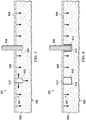
- View 300 is a view of sheet 202 after a machining operation is performed.
- sheet 202 has number of features 302.
- Number of features 302 may be a plurality of holes, or a plurality of slots.
- sheet 202 may be referred to as a perforated sheet.
- indentations 304 in machining support 204 correspond to locations of machining operations on sheet 202.
- indentations 304 in support surface 210 correspond to locations of number of features 302.
- features 302 and indentations 304 in Figure 3 is not meant to imply physical or architectural limitations to the manner in which an illustrative embodiment may be implemented.
- the quantity, size, and locations of features 302 in sheet 202 are not meant to imply physical or architectural limitations.
- Features 302 may have any desirable quantity, size, locations, and type of feature.
- Machining support 400 is a physical implementation of machining support 102 of Figure 1 . Machining support 400 may be the same as machining support 204 with indentations 304.
- Machining support 400 is configured to reduce spring back of a sheet following a machining operation on the sheet. Machining support 400 comprises porous material 402 with plurality of surfaces 404. Plurality of surfaces 404 includes support surface 406 having contour 408 configured to contact and support a sheet. Sealing material 410 covers each of plurality of surfaces 404 except support surface 406. Vacuum port 412 is configured to provide a vacuum to porous material 402.
- Sealing material 410 prevents a vacuum from escaping through plurality of surfaces 404 other than support surface 406.
- sealing material 410 on exterior surface 414 prevents vacuum from escaping exterior surface 414.
- sealing material 410 on exterior surface 416 prevents vacuum from escaping exterior surface 416.
- Vacuum port 412 extends through sealing material 410 of exterior surface 418.
- Porous material 402 takes any desirable form to transport vacuum throughout machining support 400.
- porous material 402 is an open cell foam.
- porous material 402 is a manufactured wood.
- Machining support 400 comprises indentations 420 in support surface 406, indentations 420 corresponding to locations of machining operations on the sheet.
- each of indentations 420 is larger than a corresponding feature to be machined into the sheet.
- sealing material 422 is within each of indentations 420.
- the sheet and machining support 400 form a vacuum chamber.
- indentations 420 are sealed with sealing material 422, the vacuum chamber remains throughout machining operations for corresponding features machining into the sheet.
- Machining support 500 is a physical implementation of machining support 102 of Figure 1 .
- view 502 is a view of machining operation being performed on a portion of sheet 202 between Figures 2 and 3 .
- Machining support 500 has support surface 504. Sheet 506 is held against support surface 504 of machining support 500 by vacuum 507 applied to porous material 508 of machining support 500. In view 502, feature 510 has been machined into sheet 506. Indentation 512 was formed by machining operation that created feature 510 of sheet 506.
- vacuum 507 escapes through indentation 512.
- the vacuum provided is adjusted so that vacuum 507 in porous material 508 is maintained.
- the vacuum provided to porous material 508 is adjusted to maintain a pressure differential across second surface 513 of sheet 506 to hold second surface 513 against support surface 504 of porous material 508 while the machining operation is performed on sheet 506.
- machining tool 514 is performing a machining operation on sheet 506. As depicted, machining tool 514 is extending through sheet 506 and forming indentation 516 into support surface 504. As depicted, machining tool 514 takes the form of a drill bit. Although not depicted, machining tool 514 may be attached to any desirable machine, such as a drill, a CNC machine, or any other desirable machine.
- Machining support 600 is a physical implementation of machining support 102 of Figure 1 .
- machining support 600 has support surface 604. Sheet 606 is held against support surface 604 of machining support 600 by vacuum 607 applied to porous material 608 of machining support 600.
- feature 610 has been machined into sheet 606.
- Indentation 612 and indentation 614 were formed into porous material 608 prior to holding sheet 606 against support surface 604.
- indentation 612 and indentation 614 were formed into porous material 608 while performing machining operations on a different sheet (not depicted).
- indentation 612 and indentation 614 were formed into porous material 608 while machining support 600 was manufactured.
- Indentation 612 and indentation 614 are both sealed with sealing material 616.
- Sealing material 616 substantially restricts or prevents vacuum from escaping indentation 612 and indentation 614.
- machining tool 618 is performing a machining operation on sheet 606. As depicted, machining tool 618 is extending through sheet 606 but does not contact support surface 604. As depicted, machining tool 618 does not contact porous material 608 of machining support 600. Indentation 612 and indentation 614 are larger than feature 610. By indentation 612 and indentation 614 being larger than feature 610 and machining tool 618, machining tool 618 does not contact porous material 608 while performing machining operations to form feature 610. In some illustrative examples, indentation 612 and indentation 614 are sized to take into account tolerances in the machining operations performed by machining tool 618.
- Method 700 may be implemented using machining support 102 in manufacturing environment 100 of Figure 1 .
- Method 700 may be implemented using machining support 204 of Figure 2 .
- Method 700 may be implemented to perform a machining operation on sheet 202 of Figures 2 and 3 .
- Method 700 may be implemented using machining support 400 of Figure 4 .
- Method 700 may be implemented in Figure 5 using machining support 500.
- Method 700 may be implemented in Figure 6 using machining support 600.
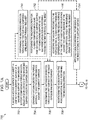
- Method 700 places a second surface of the sheet in contact with a support surface of a machining support, the machining support comprising a porous material sealed on each surface of the machining support except the support surface (operation 702 ).
- the second surface of the sheet when the second surface of the sheet is placed in contact with the support surface, only a portion of second surface of sheet is placed in contact with the support surface of the machining support.
- the sheet when the sheet has a curvature, either the periphery or the center of the sheet is not in contact with the support surface.
- Method 700 draws a vacuum across the porous material to hold the second surface against the support surface (operation 704 ).
- the vacuum can be drawn across the porous material because of the seals on the remaining surfaces of the machining support.
- the vacuum extends through the support surface and holds the second surface against the support surface.
- Method 700 performs the machining operation through a first surface of the sheet opposite the second surface (operation 706 ).
- the machining operation is any desirable operation.
- the machining operation may be drilling, milling, or any other desirable type of operation.
- Method 700 maintains the vacuum within the porous material while performing the machining operation (operation 708 ). By maintaining the vacuum within the porous material while performing the machining operation, machining force from the machining operation does not deflect the sheet. When the machining operation is performed on the sheet, the sheet is in contact with the support surface and does not deflect. Spring back of the sheet is the sheet returning to an original shape when force is removed from the sheet. By maintaining contact between the second surface of the sheet and the support surface, spring back of the sheet following the machining operation is reduced or eliminated. By maintaining contact between the second surface of the sheet and the support surface, the sheet substantially maintains its shape before and as a machining force is applied to the sheet. Afterwards, method 700 terminates.
- indentations are made in the machining support as the machining operation is performed on the sheet.
- the vacuum is maintained by adjusting the vacuum provided as indentations are made in the machining support.
- performing the machining operation through the first surface comprises drilling holes through the sheet (operation 710 ). In some illustrative examples, performing the machining operation further comprises machining indentations into the support surface of the machining support as the machining operation is performed through the first surface of the sheet (operation 712 ).
- method 700 applies a sealing material within each of the indentations in the support surface (operation 714 ).
- the sealing material is placed into each of the indentations in one sealing process after each of the indentations has been formed.
- the sealing material is applied after the sheet is removed from the support surface.
- vacuum is not lost from the indentations.
- the machining support can be used to support another sheet.
- method 700 adjusts the vacuum provided to the porous material to maintain a pressure differential across the second surface of the sheet to hold the second surface against the support surface of the porous material while the machining operation is performed on the sheet (operation 716 ).
- performing the machining operation comprises machining indentations into the support surface of the machining support (operation 718 ) as the holes are drilled into the sheet, and method 700 applies a sealing material within each of the indentations in the support surface prior to drawing the vacuum across the porous material to hold the second sheet against the support surface (operation 720 ).
- the sealing material is placed into each of the indentations in one sealing process after each of the indentations has been formed.
- the sealing material is applied after the sheet is removed from the support surface.
- the sealing material is applied within each of the indentations, vacuum is not lost from the indentations.
- the machining support can be used to support other sheets, including second sheet.
- method 700 releases the vacuum from the porous material of the machining support (operation 722 ). In some illustrative examples, method 700 removes the sheet with features created by the machining operation from the machining support after releasing the vacuum (operation 724 ). In some illustrative examples, method 700 draws a vacuum across the porous material to hold a second sheet against the support surface (operation 726 ). In some illustrative examples, method 700 performs the machining operation on the second sheet while maintaining the vacuum within the porous material (operation 728 ).
- FIG. 8 is an illustration of a flowchart of a method for forming a machining support configured to reduce spring back of a sheet following a machining operation on the sheet in accordance with an illustrative embodiment.
- Method 800 may be implemented to form machining support 102 in Figure 1 .
- Method 800 may be implemented to form machining support 204 of Figures 2 and 3 .
- Method 800 may be implemented to form machining support 400 of Figure 4 .
- Method 800 may be implemented to form machining support 500 of Figure 5 .
- Method 800 may be implemented to form machining support 600 in Figure 6 .
- Method 800 shapes porous material to create a plurality of surfaces including a support surface having a contour configured to contact and support the sheet (operation 802 ).
- Method 800 applies a sealing material to each of the plurality of surfaces except the support surface (operation 804 ).
- an applied vacuum will not escape through the sealed surfaces of the machining support.
- a vacuum applied to the porous material will escape through the support surface to hold a sheet against the support surface. Afterwards, method 800 terminates.
- method 800 machines indentations into the support surface (operation 806 ).
- the indentations are machined into the support surface prior to placing a sheet onto the support surface.
- method 800 applies sealing material to each of the indentations (operation 808 ). Sealing material within each of the indentations prevents a vacuum from escaping through the indentations. Sealing material within each of the indentations only allows vacuum to escape through the support surface of the machining support.
- each of the indentations is larger than a corresponding feature to be machined into the sheet (operation 810 ).
- the machining operation will not remove material from the support surface.
- machining tolerances are taken into account.
- machining indentations into the support surface is performed during a machining operation on the sheet, and applying the sealing material is performed after removing the sheet from the support surface (operation 812 ).
- method 800 inserts a vacuum port into the porous material (operation 814 ).
- the vacuum port provides an inlet through one of the sealed surfaces to draw a vacuum on the porous material.
- Method 900 may be implemented using machining support 102 in manufacturing environment 100 of Figure 1 .
- Method 900 may be implemented using machining support 204 of Figure 2 .
- Method 900 may be implemented to perform a machining operation on sheet 202 of Figures 2 and 3 .
- Method 900 may be implemented using machining support 400 of Figure 4 .
- Method 900 may be implemented in Figure 5 using machining support 500.
- Method 900 may be implemented in Figure 6 using machining support 600.
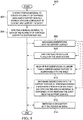
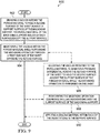
- Method 900 draws a vacuum across a porous material of a machining support to hold a second surface of the sheet against a support surface of the machining support, the porous material of the machining support sealed on each surface except the support surface (operation 902 ).
- Method 900 maintains the vacuum within the porous material while performing the machining operation through a first surface of the sheet opposite the second surface (operation 904 ). Afterwards, method 900 terminates.
- method 900 adjusts the vacuum provided to the porous material to maintain a pressure differential across the second surface of the sheet to hold the second surface against the support surface of the porous material while the machining operation is performed on the sheet (operation 906 ).
- performing the machining operation further comprises machining indentations into the support surface of the machining support as the machining operation is performed through the first surface of the sheet (operation 908 ).
- method 900 applies a sealing material within each of the indentations in the support surface (operation 910 ).
- the phrase "at least one of,” when used with a list of items, means different combinations of one or more of the listed items may be used, and only one of each item in the list may be needed. In other words, "at least one of' means any combination of items and number of items may be used from the list, but not all of the items in the list are required.
- the item may be a particular object, a thing, or a category.
- “at least one of item A, item B, or item C” may include, without limitation, item A, item A and item B, or item B. This example also may include item A, item B, and item C, or item B and item C. Of course, any combination of these items may be present. In other examples, "at least one of' may be, for example, without limitation, two of item A, one of item B, and ten of item C; four of item B and seven of item C; or other suitable combinations.
- each block in the flowcharts or block diagrams may represent a module, a segment, a function, and/or a portion of an operation or step.
- the function or functions noted in the blocks may occur out of the order noted in the figures. For example, in some cases, two blocks shown in succession may be executed substantially concurrently, or the blocks may sometimes be performed in the reverse order, depending upon the functionality involved. Also, other blocks may be added, in addition to the illustrated blocks, in a flowchart or block diagram. Some blocks may be optional. For example, in method 700, operations 710 through 728 may be optional. As another example, in method 800, operations 806 through 814 may be optional. As another example, in method 900, operations 906 through 910.
- aircraft manufacturing and service method 1000 may be described in the context of aircraft manufacturing and service method 1000 as shown in Figure 10 and aircraft 1100 as shown in Figure 11 .
- Figure 10 an illustration of an aircraft manufacturing and service method is depicted in accordance with an illustrative embodiment.
- aircraft manufacturing and service method 1000 may include specification and design 1002 of aircraft 1100 in Figure 11 and material procurement 1004.
- aircraft 1100 During production, component and subassembly manufacturing 1006 and system integration 1008 of aircraft 1100 takes place. Thereafter, aircraft 1100 may go through certification and delivery 1010 in order to be placed in service 1012. While in service 1012 by a customer, aircraft 1100 is scheduled for routine maintenance and service 1014, which may include modification, reconfiguration, refurbishment, or other maintenance and service.
- Each of the processes of aircraft manufacturing and service method 1000 may be performed or carried out by a system integrator, a third party, and/or an operator.
- the operator may be a customer.
- a system integrator may include, without limitation, any number of aircraft manufacturers and major-system subcontractors
- a third party may include, without limitation, any number of vendors, subcontractors, and suppliers
- an operator may be an airline, a leasing company, a military entity, a service organization, and so on.
- aircraft 1100 is produced by aircraft manufacturing and service method 1000 of Figure 10 and may include airframe 1102 with plurality of systems 1104 and interior 1106.
- systems 1104 include one or more of propulsion system 1108, electrical system 1110, hydraulic system 1112, and environmental system 1114. Any number of other systems may be included.
- propulsion system 1108, electrical system 1110, hydraulic system 1112, and environmental system 1114 Any number of other systems may be included.
- an aerospace example is shown, different illustrative embodiments may be applied to other industries, such as the automotive industry.
- Apparatuses and methods embodied herein may be employed during at least one of the stages of aircraft manufacturing and service method 1000.
- One or more illustrative embodiments may be used during at least one of component and subassembly manufacturing 1006, system integration 1008, or maintenance and service 1014 of Figure 10 .
- machining support 102 may be used during component and subassembly manufacturing 1006 to form a component of aircraft 1100.
- machining support 102 may be used and service 1014. Machining support 102 may be used to manufacture portions of aircraft 1100 such as airframe 1102 or portions of interior 1106.
- the illustrative examples provide a method and machining support for holding a thin sheet, such as a thin CFRP laminate, during a machining operation. Holding the sheet against the machining support keeps the sheet stable during a machining operation, such as a robotic perforation process for acoustic treatment.
- a vacuum source pulls a vacuum through a porous media, or material, shaped to the curvature of the sheet to hold the sheet against the support surface of the machining support.
- the porous media provides some local flow resistance such that total vacuum over the sheet is not lost when multiple holes, or other features, are perforated in the laminate.
- the sheet may be perforated for any desirable purpose.
- a sheet may be perforated for acoustic treatment.
- the surface of the sheet can be perforated without completely losing vacuum as would happen in a conventional vacuum hold down system relying on gasketed vacuum zones.
Landscapes
- Engineering & Computer Science (AREA)
- Mechanical Engineering (AREA)
- Blow-Moulding Or Thermoforming Of Plastics Or The Like (AREA)
- Container, Conveyance, Adherence, Positioning, Of Wafer (AREA)
- Jigs For Machine Tools (AREA)
- Details Of Cutting Devices (AREA)
- Drilling And Boring (AREA)
- Perforating, Stamping-Out Or Severing By Means Other Than Cutting (AREA)
Applications Claiming Priority (1)
| Application Number | Priority Date | Filing Date | Title |
|---|---|---|---|
| US16/297,578 US11529717B2 (en) | 2019-03-08 | 2019-03-08 | Supporting a contoured sheet of material during machining operations |
Publications (3)
| Publication Number | Publication Date |
|---|---|
| EP3705227A2 true EP3705227A2 (de) | 2020-09-09 |
| EP3705227A3 EP3705227A3 (de) | 2020-10-14 |
| EP3705227B1 EP3705227B1 (de) | 2023-12-27 |
Family
ID=69172644
Family Applications (1)
| Application Number | Title | Priority Date | Filing Date |
|---|---|---|---|
| EP20151881.8A Active EP3705227B1 (de) | 2019-03-08 | 2020-01-15 | Abstützung einer konturierten materialbahn bei bearbeitungsvorgängen |
Country Status (6)
| Country | Link |
|---|---|
| US (1) | US11529717B2 (de) |
| EP (1) | EP3705227B1 (de) |
| JP (1) | JP7515252B2 (de) |
| CN (1) | CN111660120B (de) |
| AU (1) | AU2020201544B2 (de) |
| RU (1) | RU2019141069A (de) |
Cited By (1)
| Publication number | Priority date | Publication date | Assignee | Title |
|---|---|---|---|---|
| CN113894309A (zh) * | 2021-10-30 | 2022-01-07 | 浙江吉尚汽车部件有限公司 | 泵体上钻孔加工方法 |
Families Citing this family (1)
| Publication number | Priority date | Publication date | Assignee | Title |
|---|---|---|---|---|
| JP7583261B2 (ja) * | 2021-01-26 | 2024-11-14 | 株式会社不二越 | 吸着プレートおよびその製造方法 |
Family Cites Families (11)
| Publication number | Priority date | Publication date | Assignee | Title |
|---|---|---|---|---|
| US2756644A (en) | 1953-09-04 | 1956-07-31 | Gordon N Steele | Vacuum fixture |
| JPS60103651U (ja) | 1983-12-19 | 1985-07-15 | シチズン時計株式会社 | 真空吸着台 |
| GB2172822B (en) * | 1985-03-25 | 1988-09-01 | Furniture Ind Res Ass | Vacuum chucks |
| JPS6215041A (ja) * | 1985-06-17 | 1987-01-23 | Hitachi Electronics Eng Co Ltd | チャック装置 |
| US5141212A (en) * | 1991-04-08 | 1992-08-25 | Ekstrom Carlson & Co. | Vacuum chuck with foam workpiece-supporting surface |
| JP2008087131A (ja) * | 2006-10-04 | 2008-04-17 | Snc:Kk | 易削性被加工材の加工テーブルおよび固定方法ならびに加工テーブル用アタッチメント板 |
| US20110135411A1 (en) * | 2009-12-03 | 2011-06-09 | Inman John E | Drill template with integral vacuum attach having plugs |
| US8641337B2 (en) | 2010-09-13 | 2014-02-04 | Thermwood Corporation | Method of forming parts on a CNC machine |
| JP2012135838A (ja) * | 2010-12-27 | 2012-07-19 | Kyocera Corp | 載置用部材 |
| JP2014072510A (ja) * | 2012-10-02 | 2014-04-21 | Disco Abrasive Syst Ltd | チャックテーブル |
| CN105522724B (zh) * | 2014-10-24 | 2019-06-04 | 波音公司 | 真空压实装置和对丝束进行压实的方法 |
-
2019
- 2019-03-08 US US16/297,578 patent/US11529717B2/en active Active
- 2019-12-12 RU RU2019141069A patent/RU2019141069A/ru unknown
- 2019-12-17 JP JP2019227505A patent/JP7515252B2/ja active Active
-
2020
- 2020-01-09 CN CN202010022184.7A patent/CN111660120B/zh active Active
- 2020-01-15 EP EP20151881.8A patent/EP3705227B1/de active Active
- 2020-03-03 AU AU2020201544A patent/AU2020201544B2/en active Active
Cited By (2)
| Publication number | Priority date | Publication date | Assignee | Title |
|---|---|---|---|---|
| CN113894309A (zh) * | 2021-10-30 | 2022-01-07 | 浙江吉尚汽车部件有限公司 | 泵体上钻孔加工方法 |
| CN113894309B (zh) * | 2021-10-30 | 2022-07-12 | 浙江吉尚汽车部件有限公司 | 泵体上钻孔加工方法 |
Also Published As
| Publication number | Publication date |
|---|---|
| US20200282525A1 (en) | 2020-09-10 |
| JP2020142358A (ja) | 2020-09-10 |
| RU2019141069A (ru) | 2021-06-15 |
| EP3705227B1 (de) | 2023-12-27 |
| AU2020201544A1 (en) | 2020-09-24 |
| AU2020201544B2 (en) | 2025-04-10 |
| CN111660120B (zh) | 2024-12-10 |
| US11529717B2 (en) | 2022-12-20 |
| JP7515252B2 (ja) | 2024-07-12 |
| EP3705227A3 (de) | 2020-10-14 |
| CN111660120A (zh) | 2020-09-15 |
Similar Documents
| Publication | Publication Date | Title |
|---|---|---|
| US12208453B2 (en) | Controlling spring back of a sheet of material following machining operations | |
| AU2020201544B2 (en) | Supporting a contoured sheet of material during machining operations | |
| US11498170B2 (en) | Surface area of fixtures | |
| US8696843B1 (en) | Repair of acoustically treated structures | |
| EP3492247B1 (de) | Strukturelle überarbeitung von zellkernplatten | |
| EP2980420B1 (de) | Tafeleinsatzanordnung und verfahren | |
| EP2415664B1 (de) | Flügel-Rumpf-Flugzeugverkleidung mit aufsprühbarem Schaum | |
| US10300569B2 (en) | Method for fabricating vacuum fixturing using granular media | |
| US10124449B2 (en) | Temporary fastener for simultaneous workpiece and drill jig clamping | |
| CN109604663A (zh) | 一种碳纤维夹芯-铝合金层叠材料高精孔加工方法 | |
| US8973241B1 (en) | Method and apparatus for joining composite structures | |
| EP2982478B1 (de) | Verfahren zur glättung von faltigem material und vorrichtung | |
| EP3702098B1 (de) | Verfahren und vorrichtungen zur bearbeitung eines gekühlten werkstücks | |
| CN111941806A (zh) | 使用镁叶片制造复合结构的方法与系统 | |
| CN113246491A (zh) | 柔性双面真空板载体 | |
| CN109894817B (zh) | 一种尖角特征加工方法 | |
| Bitzer | Honeycomb processes | |
| US20060086474A1 (en) | Method of venting a spray metal mold | |
| JP2024073366A (ja) | 製造時間を短縮した複合材製造 | |
| WO1999017925A1 (en) | Sheet material for core support |
Legal Events
| Date | Code | Title | Description |
|---|---|---|---|
| PUAI | Public reference made under article 153(3) epc to a published international application that has entered the european phase |
Free format text: ORIGINAL CODE: 0009012 |
|
| STAA | Information on the status of an ep patent application or granted ep patent |
Free format text: STATUS: THE APPLICATION HAS BEEN PUBLISHED |
|
| AK | Designated contracting states |
Kind code of ref document: A2 Designated state(s): AL AT BE BG CH CY CZ DE DK EE ES FI FR GB GR HR HU IE IS IT LI LT LU LV MC MK MT NL NO PL PT RO RS SE SI SK SM TR |
|
| AX | Request for extension of the european patent |
Extension state: BA ME |
|
| PUAL | Search report despatched |
Free format text: ORIGINAL CODE: 0009013 |
|
| AK | Designated contracting states |
Kind code of ref document: A3 Designated state(s): AL AT BE BG CH CY CZ DE DK EE ES FI FR GB GR HR HU IE IS IT LI LT LU LV MC MK MT NL NO PL PT RO RS SE SI SK SM TR |
|
| AX | Request for extension of the european patent |
Extension state: BA ME |
|
| RIC1 | Information provided on ipc code assigned before grant |
Ipc: B23Q 3/08 20060101ALI20200904BHEP Ipc: B23Q 3/06 20060101AFI20200904BHEP |
|
| STAA | Information on the status of an ep patent application or granted ep patent |
Free format text: STATUS: REQUEST FOR EXAMINATION WAS MADE |
|
| 17P | Request for examination filed |
Effective date: 20210407 |
|
| RBV | Designated contracting states (corrected) |
Designated state(s): AL AT BE BG CH CY CZ DE DK EE ES FI FR GB GR HR HU IE IS IT LI LT LU LV MC MK MT NL NO PL PT RO RS SE SI SK SM TR |
|
| RAP3 | Party data changed (applicant data changed or rights of an application transferred) |
Owner name: THE BOEING COMPANY |
|
| GRAP | Despatch of communication of intention to grant a patent |
Free format text: ORIGINAL CODE: EPIDOSNIGR1 |
|
| STAA | Information on the status of an ep patent application or granted ep patent |
Free format text: STATUS: GRANT OF PATENT IS INTENDED |
|
| INTG | Intention to grant announced |
Effective date: 20230428 |
|
| GRAJ | Information related to disapproval of communication of intention to grant by the applicant or resumption of examination proceedings by the epo deleted |
Free format text: ORIGINAL CODE: EPIDOSDIGR1 |
|
| STAA | Information on the status of an ep patent application or granted ep patent |
Free format text: STATUS: REQUEST FOR EXAMINATION WAS MADE |
|
| GRAP | Despatch of communication of intention to grant a patent |
Free format text: ORIGINAL CODE: EPIDOSNIGR1 |
|
| STAA | Information on the status of an ep patent application or granted ep patent |
Free format text: STATUS: GRANT OF PATENT IS INTENDED |
|
| INTC | Intention to grant announced (deleted) | ||
| INTG | Intention to grant announced |
Effective date: 20230720 |
|
| GRAS | Grant fee paid |
Free format text: ORIGINAL CODE: EPIDOSNIGR3 |
|
| GRAA | (expected) grant |
Free format text: ORIGINAL CODE: 0009210 |
|
| STAA | Information on the status of an ep patent application or granted ep patent |
Free format text: STATUS: THE PATENT HAS BEEN GRANTED |
|
| AK | Designated contracting states |
Kind code of ref document: B1 Designated state(s): AL AT BE BG CH CY CZ DE DK EE ES FI FR GB GR HR HU IE IS IT LI LT LU LV MC MK MT NL NO PL PT RO RS SE SI SK SM TR |
|
| P01 | Opt-out of the competence of the unified patent court (upc) registered |
Effective date: 20231120 |
|
| REG | Reference to a national code |
Ref country code: GB Ref legal event code: FG4D |
|
| REG | Reference to a national code |
Ref country code: CH Ref legal event code: EP |
|
| REG | Reference to a national code |
Ref country code: DE Ref legal event code: R096 Ref document number: 602020023237 Country of ref document: DE |
|
| REG | Reference to a national code |
Ref country code: IE Ref legal event code: FG4D |
|
| PG25 | Lapsed in a contracting state [announced via postgrant information from national office to epo] |
Ref country code: GR Free format text: LAPSE BECAUSE OF FAILURE TO SUBMIT A TRANSLATION OF THE DESCRIPTION OR TO PAY THE FEE WITHIN THE PRESCRIBED TIME-LIMIT Effective date: 20240328 |
|
| REG | Reference to a national code |
Ref country code: LT Ref legal event code: MG9D |
|
| PG25 | Lapsed in a contracting state [announced via postgrant information from national office to epo] |
Ref country code: LT Free format text: LAPSE BECAUSE OF FAILURE TO SUBMIT A TRANSLATION OF THE DESCRIPTION OR TO PAY THE FEE WITHIN THE PRESCRIBED TIME-LIMIT Effective date: 20231227 |
|
| PG25 | Lapsed in a contracting state [announced via postgrant information from national office to epo] |
Ref country code: ES Free format text: LAPSE BECAUSE OF FAILURE TO SUBMIT A TRANSLATION OF THE DESCRIPTION OR TO PAY THE FEE WITHIN THE PRESCRIBED TIME-LIMIT Effective date: 20231227 |
|
| PG25 | Lapsed in a contracting state [announced via postgrant information from national office to epo] |
Ref country code: LT Free format text: LAPSE BECAUSE OF FAILURE TO SUBMIT A TRANSLATION OF THE DESCRIPTION OR TO PAY THE FEE WITHIN THE PRESCRIBED TIME-LIMIT Effective date: 20231227 Ref country code: GR Free format text: LAPSE BECAUSE OF FAILURE TO SUBMIT A TRANSLATION OF THE DESCRIPTION OR TO PAY THE FEE WITHIN THE PRESCRIBED TIME-LIMIT Effective date: 20240328 Ref country code: FI Free format text: LAPSE BECAUSE OF FAILURE TO SUBMIT A TRANSLATION OF THE DESCRIPTION OR TO PAY THE FEE WITHIN THE PRESCRIBED TIME-LIMIT Effective date: 20231227 Ref country code: ES Free format text: LAPSE BECAUSE OF FAILURE TO SUBMIT A TRANSLATION OF THE DESCRIPTION OR TO PAY THE FEE WITHIN THE PRESCRIBED TIME-LIMIT Effective date: 20231227 Ref country code: BG Free format text: LAPSE BECAUSE OF FAILURE TO SUBMIT A TRANSLATION OF THE DESCRIPTION OR TO PAY THE FEE WITHIN THE PRESCRIBED TIME-LIMIT Effective date: 20240327 |
|
| REG | Reference to a national code |
Ref country code: NL Ref legal event code: MP Effective date: 20231227 |
|
| REG | Reference to a national code |
Ref country code: AT Ref legal event code: MK05 Ref document number: 1644085 Country of ref document: AT Kind code of ref document: T Effective date: 20231227 |
|
| PG25 | Lapsed in a contracting state [announced via postgrant information from national office to epo] |
Ref country code: NL Free format text: LAPSE BECAUSE OF FAILURE TO SUBMIT A TRANSLATION OF THE DESCRIPTION OR TO PAY THE FEE WITHIN THE PRESCRIBED TIME-LIMIT Effective date: 20231227 |
|
| PG25 | Lapsed in a contracting state [announced via postgrant information from national office to epo] |
Ref country code: SE Free format text: LAPSE BECAUSE OF FAILURE TO SUBMIT A TRANSLATION OF THE DESCRIPTION OR TO PAY THE FEE WITHIN THE PRESCRIBED TIME-LIMIT Effective date: 20231227 Ref country code: RS Free format text: LAPSE BECAUSE OF FAILURE TO SUBMIT A TRANSLATION OF THE DESCRIPTION OR TO PAY THE FEE WITHIN THE PRESCRIBED TIME-LIMIT Effective date: 20231227 Ref country code: NO Free format text: LAPSE BECAUSE OF FAILURE TO SUBMIT A TRANSLATION OF THE DESCRIPTION OR TO PAY THE FEE WITHIN THE PRESCRIBED TIME-LIMIT Effective date: 20240327 Ref country code: NL Free format text: LAPSE BECAUSE OF FAILURE TO SUBMIT A TRANSLATION OF THE DESCRIPTION OR TO PAY THE FEE WITHIN THE PRESCRIBED TIME-LIMIT Effective date: 20231227 Ref country code: LV Free format text: LAPSE BECAUSE OF FAILURE TO SUBMIT A TRANSLATION OF THE DESCRIPTION OR TO PAY THE FEE WITHIN THE PRESCRIBED TIME-LIMIT Effective date: 20231227 Ref country code: HR Free format text: LAPSE BECAUSE OF FAILURE TO SUBMIT A TRANSLATION OF THE DESCRIPTION OR TO PAY THE FEE WITHIN THE PRESCRIBED TIME-LIMIT Effective date: 20231227 |
|
| PG25 | Lapsed in a contracting state [announced via postgrant information from national office to epo] |
Ref country code: IS Free format text: LAPSE BECAUSE OF FAILURE TO SUBMIT A TRANSLATION OF THE DESCRIPTION OR TO PAY THE FEE WITHIN THE PRESCRIBED TIME-LIMIT Effective date: 20240427 |
|
| PG25 | Lapsed in a contracting state [announced via postgrant information from national office to epo] |
Ref country code: CZ Free format text: LAPSE BECAUSE OF FAILURE TO SUBMIT A TRANSLATION OF THE DESCRIPTION OR TO PAY THE FEE WITHIN THE PRESCRIBED TIME-LIMIT Effective date: 20231227 Ref country code: AT Free format text: LAPSE BECAUSE OF FAILURE TO SUBMIT A TRANSLATION OF THE DESCRIPTION OR TO PAY THE FEE WITHIN THE PRESCRIBED TIME-LIMIT Effective date: 20231227 |
|
| PG25 | Lapsed in a contracting state [announced via postgrant information from national office to epo] |
Ref country code: SK Free format text: LAPSE BECAUSE OF FAILURE TO SUBMIT A TRANSLATION OF THE DESCRIPTION OR TO PAY THE FEE WITHIN THE PRESCRIBED TIME-LIMIT Effective date: 20231227 |
|
| PG25 | Lapsed in a contracting state [announced via postgrant information from national office to epo] |
Ref country code: SM Free format text: LAPSE BECAUSE OF FAILURE TO SUBMIT A TRANSLATION OF THE DESCRIPTION OR TO PAY THE FEE WITHIN THE PRESCRIBED TIME-LIMIT Effective date: 20231227 Ref country code: SK Free format text: LAPSE BECAUSE OF FAILURE TO SUBMIT A TRANSLATION OF THE DESCRIPTION OR TO PAY THE FEE WITHIN THE PRESCRIBED TIME-LIMIT Effective date: 20231227 Ref country code: RO Free format text: LAPSE BECAUSE OF FAILURE TO SUBMIT A TRANSLATION OF THE DESCRIPTION OR TO PAY THE FEE WITHIN THE PRESCRIBED TIME-LIMIT Effective date: 20231227 Ref country code: IT Free format text: LAPSE BECAUSE OF FAILURE TO SUBMIT A TRANSLATION OF THE DESCRIPTION OR TO PAY THE FEE WITHIN THE PRESCRIBED TIME-LIMIT Effective date: 20231227 Ref country code: IS Free format text: LAPSE BECAUSE OF FAILURE TO SUBMIT A TRANSLATION OF THE DESCRIPTION OR TO PAY THE FEE WITHIN THE PRESCRIBED TIME-LIMIT Effective date: 20240427 Ref country code: EE Free format text: LAPSE BECAUSE OF FAILURE TO SUBMIT A TRANSLATION OF THE DESCRIPTION OR TO PAY THE FEE WITHIN THE PRESCRIBED TIME-LIMIT Effective date: 20231227 Ref country code: CZ Free format text: LAPSE BECAUSE OF FAILURE TO SUBMIT A TRANSLATION OF THE DESCRIPTION OR TO PAY THE FEE WITHIN THE PRESCRIBED TIME-LIMIT Effective date: 20231227 Ref country code: AT Free format text: LAPSE BECAUSE OF FAILURE TO SUBMIT A TRANSLATION OF THE DESCRIPTION OR TO PAY THE FEE WITHIN THE PRESCRIBED TIME-LIMIT Effective date: 20231227 |
|
| PG25 | Lapsed in a contracting state [announced via postgrant information from national office to epo] |
Ref country code: PT Free format text: LAPSE BECAUSE OF FAILURE TO SUBMIT A TRANSLATION OF THE DESCRIPTION OR TO PAY THE FEE WITHIN THE PRESCRIBED TIME-LIMIT Effective date: 20240429 Ref country code: PL Free format text: LAPSE BECAUSE OF FAILURE TO SUBMIT A TRANSLATION OF THE DESCRIPTION OR TO PAY THE FEE WITHIN THE PRESCRIBED TIME-LIMIT Effective date: 20231227 |
|
| PG25 | Lapsed in a contracting state [announced via postgrant information from national office to epo] |
Ref country code: PT Free format text: LAPSE BECAUSE OF FAILURE TO SUBMIT A TRANSLATION OF THE DESCRIPTION OR TO PAY THE FEE WITHIN THE PRESCRIBED TIME-LIMIT Effective date: 20240429 Ref country code: PL Free format text: LAPSE BECAUSE OF FAILURE TO SUBMIT A TRANSLATION OF THE DESCRIPTION OR TO PAY THE FEE WITHIN THE PRESCRIBED TIME-LIMIT Effective date: 20231227 |
|
| REG | Reference to a national code |
Ref country code: CH Ref legal event code: PL |
|
| PG25 | Lapsed in a contracting state [announced via postgrant information from national office to epo] |
Ref country code: LU Free format text: LAPSE BECAUSE OF NON-PAYMENT OF DUE FEES Effective date: 20240115 |
|
| PG25 | Lapsed in a contracting state [announced via postgrant information from national office to epo] |
Ref country code: LU Free format text: LAPSE BECAUSE OF NON-PAYMENT OF DUE FEES Effective date: 20240115 Ref country code: MC Free format text: LAPSE BECAUSE OF FAILURE TO SUBMIT A TRANSLATION OF THE DESCRIPTION OR TO PAY THE FEE WITHIN THE PRESCRIBED TIME-LIMIT Effective date: 20231227 |
|
| REG | Reference to a national code |
Ref country code: DE Ref legal event code: R097 Ref document number: 602020023237 Country of ref document: DE |
|
| PG25 | Lapsed in a contracting state [announced via postgrant information from national office to epo] |
Ref country code: DK Free format text: LAPSE BECAUSE OF FAILURE TO SUBMIT A TRANSLATION OF THE DESCRIPTION OR TO PAY THE FEE WITHIN THE PRESCRIBED TIME-LIMIT Effective date: 20231227 |
|
| PG25 | Lapsed in a contracting state [announced via postgrant information from national office to epo] |
Ref country code: BE Free format text: LAPSE BECAUSE OF NON-PAYMENT OF DUE FEES Effective date: 20240131 |
|
| PG25 | Lapsed in a contracting state [announced via postgrant information from national office to epo] |
Ref country code: CH Free format text: LAPSE BECAUSE OF NON-PAYMENT OF DUE FEES Effective date: 20240131 |
|
| PG25 | Lapsed in a contracting state [announced via postgrant information from national office to epo] |
Ref country code: DK Free format text: LAPSE BECAUSE OF FAILURE TO SUBMIT A TRANSLATION OF THE DESCRIPTION OR TO PAY THE FEE WITHIN THE PRESCRIBED TIME-LIMIT Effective date: 20231227 Ref country code: CH Free format text: LAPSE BECAUSE OF NON-PAYMENT OF DUE FEES Effective date: 20240131 Ref country code: BE Free format text: LAPSE BECAUSE OF NON-PAYMENT OF DUE FEES Effective date: 20240131 |
|
| PLBE | No opposition filed within time limit |
Free format text: ORIGINAL CODE: 0009261 |
|
| STAA | Information on the status of an ep patent application or granted ep patent |
Free format text: STATUS: NO OPPOSITION FILED WITHIN TIME LIMIT |
|
| REG | Reference to a national code |
Ref country code: BE Ref legal event code: MM Effective date: 20240131 |
|
| 26N | No opposition filed |
Effective date: 20240930 |
|
| PG25 | Lapsed in a contracting state [announced via postgrant information from national office to epo] |
Ref country code: IE Free format text: LAPSE BECAUSE OF NON-PAYMENT OF DUE FEES Effective date: 20240115 |
|
| PG25 | Lapsed in a contracting state [announced via postgrant information from national office to epo] |
Ref country code: IE Free format text: LAPSE BECAUSE OF NON-PAYMENT OF DUE FEES Effective date: 20240115 |
|
| PG25 | Lapsed in a contracting state [announced via postgrant information from national office to epo] |
Ref country code: SI Free format text: LAPSE BECAUSE OF FAILURE TO SUBMIT A TRANSLATION OF THE DESCRIPTION OR TO PAY THE FEE WITHIN THE PRESCRIBED TIME-LIMIT Effective date: 20231227 |
|
| PG25 | Lapsed in a contracting state [announced via postgrant information from national office to epo] |
Ref country code: CY Free format text: LAPSE BECAUSE OF FAILURE TO SUBMIT A TRANSLATION OF THE DESCRIPTION OR TO PAY THE FEE WITHIN THE PRESCRIBED TIME-LIMIT; INVALID AB INITIO Effective date: 20200115 |
|
| PG25 | Lapsed in a contracting state [announced via postgrant information from national office to epo] |
Ref country code: HU Free format text: LAPSE BECAUSE OF FAILURE TO SUBMIT A TRANSLATION OF THE DESCRIPTION OR TO PAY THE FEE WITHIN THE PRESCRIBED TIME-LIMIT; INVALID AB INITIO Effective date: 20200115 |
|
| PG25 | Lapsed in a contracting state [announced via postgrant information from national office to epo] |
Ref country code: TR Free format text: LAPSE BECAUSE OF FAILURE TO SUBMIT A TRANSLATION OF THE DESCRIPTION OR TO PAY THE FEE WITHIN THE PRESCRIBED TIME-LIMIT Effective date: 20231227 |
|
| PGFP | Annual fee paid to national office [announced via postgrant information from national office to epo] |
Ref country code: GB Payment date: 20260127 Year of fee payment: 7 |
|
| PGFP | Annual fee paid to national office [announced via postgrant information from national office to epo] |
Ref country code: DE Payment date: 20260128 Year of fee payment: 7 |
|
| PGFP | Annual fee paid to national office [announced via postgrant information from national office to epo] |
Ref country code: FR Payment date: 20260126 Year of fee payment: 7 |