EP3705096B1 - Ohrstöpsel mit erhöhtem tragekomfort - Google Patents
Ohrstöpsel mit erhöhtem tragekomfort Download PDFInfo
- Publication number
- EP3705096B1 EP3705096B1 EP19175174.2A EP19175174A EP3705096B1 EP 3705096 B1 EP3705096 B1 EP 3705096B1 EP 19175174 A EP19175174 A EP 19175174A EP 3705096 B1 EP3705096 B1 EP 3705096B1
- Authority
- EP
- European Patent Office
- Prior art keywords
- filling cavity
- earplug
- compression
- air
- cavity
- Prior art date
- Legal status (The legal status is an assumption and is not a legal conclusion. Google has not performed a legal analysis and makes no representation as to the accuracy of the status listed.)
- Not-in-force
Links
Images


Classifications
-
- A—HUMAN NECESSITIES
- A61—MEDICAL OR VETERINARY SCIENCE; HYGIENE
- A61F—FILTERS IMPLANTABLE INTO BLOOD VESSELS; PROSTHESES; DEVICES PROVIDING PATENCY TO, OR PREVENTING COLLAPSING OF, TUBULAR STRUCTURES OF THE BODY, e.g. STENTS; ORTHOPAEDIC, NURSING OR CONTRACEPTIVE DEVICES; FOMENTATION; TREATMENT OR PROTECTION OF EYES OR EARS; BANDAGES, DRESSINGS OR ABSORBENT PADS; FIRST-AID KITS
- A61F11/00—Methods or devices for treatment of the ears or hearing sense; Non-electric hearing aids; Methods or devices for enabling ear patients to achieve auditory perception through physiological senses other than hearing sense; Protective devices for the ears, carried on the body or in the hand
- A61F11/06—Protective devices for the ears
- A61F11/08—Protective devices for the ears internal, e.g. earplugs
- A61F11/085—Protective devices for the ears internal, e.g. earplugs including an inner channel
-
- A—HUMAN NECESSITIES
- A61—MEDICAL OR VETERINARY SCIENCE; HYGIENE
- A61F—FILTERS IMPLANTABLE INTO BLOOD VESSELS; PROSTHESES; DEVICES PROVIDING PATENCY TO, OR PREVENTING COLLAPSING OF, TUBULAR STRUCTURES OF THE BODY, e.g. STENTS; ORTHOPAEDIC, NURSING OR CONTRACEPTIVE DEVICES; FOMENTATION; TREATMENT OR PROTECTION OF EYES OR EARS; BANDAGES, DRESSINGS OR ABSORBENT PADS; FIRST-AID KITS
- A61F11/00—Methods or devices for treatment of the ears or hearing sense; Non-electric hearing aids; Methods or devices for enabling ear patients to achieve auditory perception through physiological senses other than hearing sense; Protective devices for the ears, carried on the body or in the hand
- A61F11/06—Protective devices for the ears
- A61F11/08—Protective devices for the ears internal, e.g. earplugs
- A61F11/10—Protective devices for the ears internal, e.g. earplugs inflatable or expandable
Definitions
- the present invention relates to an earplug, and more particularly to an earplug 10, 10' that is inserted and worn inside a person's ear canal 60, and uses circulation of air to enhance comfortability when wearing.
- Earplugs are mainly used for placing inside a person's ear canal to completely cut off noise from entering the ear to achieve protection of the person's ear canal.
- earplugs products mainly use an integral body formed from foam or silicone to produce a multi-disc umbrella shaped body that facilitates placement inside a person's ear canal to achieve a protection effect.
- these types of earplug products easily result in discomfort in the person's ear canal, and is unable to satisfy various different types of ear canals.
- U.S. Patent No. 9326059 discloses another type of inflatable ear protector product, which is configured with a plurality of bags that are assembled and mutually connected using an encircling center method.
- the plurality of bags are concurrently inflated, however, during inflation, this type of inflatable ear protector product similarly disallows the separate adjustment of the inflation state of the plurality of bags, which not only easily causes discomfort when wearing the ear protector, but is also unsuitable for various different types of ear canals, and thus unable to satisfy various different ear canals, resulting in poor application effectiveness.
- Document GB-A-1274274 discloses the most relevant prior art.
- the technical problems the present invention intends to resolve and objectives thereof involves providing an earplug with enhanced wearing comfortability.
- the main object of the present invention lies in providing an earplug, and more particularly to an earplug that is inserted and worn inside a person's ear canal, and uses circulation of air to enhance comfortability when wearing.
- an earplug with enhanced wearing comfortability of the present invention comprises a main guide body, a supporting stem, and a filler material provided with plasticity.
- the main guide body further comprises a guide portion, a compression portion that extends from the guide portion, and a stop portion that extends from the compression portion.
- a connecting cavity is provided inside the guide portion, a filling cavity is provided inside the compression portion, and an opening portion is provided inside the stop portion. The filling cavity interconnects the connecting cavity and the opening portion.
- the supporting stem is provided with a connecting section that enables embedding into the connecting cavity, an extended section that extends from the connecting section and is positioned inside the filling cavity, and a securing section that extends from the extended section and embeds within the opening portion.
- the securing section is provided with an air passage, which enables air to circulate between the exterior of the main guide body and the interior of the filling cavity by passing through the air passage.
- the filler material fills the interior of the filling cavity to enable an air chamber that can contain air to form therein, thereby enabling air to enter the air chamber through the air passage for the compression portion to maintain its original state.
- the compression portion compresses the air within the air chamber through the filler material, thereby expelling the air through the air passage and causing the compression portion to form a compressed state.
- air enters the air chamber through the air passage and squeezes the filler material, which causes the compression portion to return to its original state from a compressed state.
- the compression portion is further assembled from a first compression area connected to the guide portion and a second compression area that extends from the first compression area and is connected to the stop portion.
- the filling cavity is further is assembled from a first filling cavity that is positioned inside the first compression area and a second filling cavity that is positioned inside the second compression area and connects with the air passage; moreover, the first filling cavity and the second filling cavity are interconnected.
- the filler material fills the first filling cavity and a portion of the second filling cavity, and the air chamber is formed inside the second filling cavity.
- a mutually embedding structure is formed between the opening portion and the securing section.
- the embedding structure comprises a first embedding portion positioned at the opening portion and a second embedding portion positioned on the securing section and embedded into the first embedding portion.
- both the guide portion and the stop portion assume an umbrella form.
- the filler material is formed from silicone material.
- the supporting stem further comprises a holding section extending from the securing section to the outer side of the opening portion, and the holding section extends to the exterior of the main guide body.
- the earplug of the present invention has the following advantages compared to the prior art: When inserting the earplug into a person's ear canal, the compression portion compresses in accordance with changes in the shape of the person's ear canal, and the shape of the compression portion changes through air adjustment to achieve enhanced comfortability when wearing the earplug.
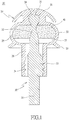
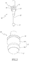
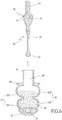
- an earplug 10 comprises a main guide body 20, a supporting stem 30, and a filler material 40.
- the main guide body 20 further comprises a guide portion 21, a compression portion 22 that extends from the guide portion 21, and a stop portion 23 that extends from the compression portion 22, all arranged in an axial configuration.
- the exterior of the guide portion 21 assumes an umbrella form, and a connecting cavity 24 is provided inside the guide portion 21.
- a filling cavity 25 is provided inside the compression portion 22, the exterior of the stop portion 23 assumes an umbrella form, and an opening portion 26 is provided inside the stop portion 23.
- the filling cavity 25 interconnects the connecting cavity 24 and the opening portion 26.
- the supporting stem 30 that extends along the same axial direction as the main guide body 20 is provided with a connecting section 31 that enables embedding into the connecting cavity 24, an extended section 32 that extends from the connecting section 31 and is positioned inside the filling cavity 25, and a securing section 33 that extends from the extended section 32 and embeds within the opening portion 26.
- the securing section 33 is provided with an air passage 34, which enables air to pass therethrough (not shown in the drawing) and circulate between the exterior of the main guide body 20 and the interior of the filling cavity 25.
- a holding section 35 further extends outward to the exterior of the main guide body 20 from the securing section 33.
- the filler material 40 is provided with plasticity and fills the interior of the filling cavity 25 to enable an air chamber 27 to form therein and contain air. Air can enter the air chamber 27 through the air passage 34 for the compression portion 22 to maintain an original state.
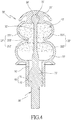
- a compression portion 22' further comprises a first compression area 221' that extends from a guide portion 21' and a second compression area 222' that extends from the first compression area 221'.
- the second compression area 222' is connected to a stop portion 23', and a filling cavity 25' further comprises a first filling cavity 251' that is positioned inside the first compression area 221' and a second filling cavity 252' that is positioned inside the second compression area 222', wherein a passage cavity 253' provides interconnection between the first filling cavity 251' and the second filling cavity 252'.
- the diameter of the passage cavity 253' is smaller than the diameters of both the first filling cavity 251' and the second filling cavity 252', and the diameter of the first filling cavity 251' is slightly smaller than that of the second filling cavity 252'.
- the second filling cavity 252' is connected to an opening portion 26', and a filler material 40' respectively fills the first filling cavity 251', the passage cavity 253', and the interior of the second filling cavity 252'.
- a filler material 40' respectively fills the first filling cavity 251', the passage cavity 253', and the interior of the second filling cavity 252'.
- an air chamber 27' is positioned inside the second filling cavity 252' and connects to an air passage 34'.
- the filler material 40' in the second embodiment is formed from silicone material, and the silicone filler material 40' is first heated to form a liquid, after which the liquid silicone material is injected into the interior of the main guide body 20'. It is important to explain that the liquid silicone material does not completely fill the interior of the second filling cavity 252' when injecting the liquid silicone material into the interior of the main guide body 20'.
- the supporting stem 30' is disposed into the interior of the main guide body 20' before the liquid silicone material has cooled down to enable inserting and embedding a connecting section 31' of the supporting stem 30' into a connecting cavity 24' while enabling an extended section 32' to extend into the filling cavity 25'.
- an embedding structure 50 is further configured between a securing section 33' and the opening portion 26', wherein the embedding structure 50 comprises: a first embedding portion 51 positioned at the opening portion 26' and a second embedding portion 52 positioned on the securing section 33' and embedded into the first embedding portion 51. Accordingly, when the supporting stem 30' is disposed into the interior of the main guide body 20', apart from embedding the connecting section 31' into the connecting cavity 24', the supporting stem 30' is also embedded into the opening portion 26' by means of the securing section 33', thereby enabling the supporting stem 30' to effectively embed into the main guide body 20' and preventing separation from occurring between the supporting stem 30' and the main guide body 20'.
- a silicone material is caused to solidify inside the filling cavity 25' and form the filler material 40' using a cooling or photocuring method, which also causes the air chamber 27' to form within the second filling cavity 252', thereby enabling air to pass through the air passage 34' on the supporting stem 30' from the exterior of the main guide body 20' and enter the air chamber 27', which further enables the compression portion 22' to maintain its original state.
- the filler material 40' After deforming, the filler material 40' produces a pushing force toward the air chamber 27' that squeezes and expels the air therein to the exterior of the main guide body 20' through the air passage 34', thereby causing the compression portion 22' to form a compressed state and enabling the stop portion 23' to block the entrance area of the person's ear canal 60. Accordingly, apart from enabling the compression portion 22' to produce a more favorable contact effect with the person's ear canal 60, the earplug 10' achieves better airtightness within the person's ear canal 60.
- compression of the compression portion 22' by the person's ear canal 60 compresses the filler material 40', which then squeezes and expels the air out to effectively reduce the pressure within the earplug 10', thereby enhancing comfortability when wearing the earplug 10'.
- the pressure produced by the ear wall on the compression portion 22' also gradually decreases along with a correspondingly gradual decrease in the pushing force of the filler material 40' on the air, at which time the pressure within the air chamber 27' is less than the atmospheric pressure outside the person's ear canal 60, which causes air to gradually enter the air chamber 27' through the air passage 34' and compress the filler material 40' until the earplug 10' is completely separated from the person's ear canal 60, whereupon the filler material 40' continues to be compressed by the air, causing the compression portion 22' to return to its original state from a compressed state, thereby further providing the earplug 10' with the effect of reusability and substantially extending the serviceable life thereof.
Landscapes
- Health & Medical Sciences (AREA)
- Life Sciences & Earth Sciences (AREA)
- Biomedical Technology (AREA)
- Acoustics & Sound (AREA)
- Biophysics (AREA)
- Otolaryngology (AREA)
- Psychology (AREA)
- Engineering & Computer Science (AREA)
- Physics & Mathematics (AREA)
- Heart & Thoracic Surgery (AREA)
- Vascular Medicine (AREA)
- Animal Behavior & Ethology (AREA)
- General Health & Medical Sciences (AREA)
- Public Health (AREA)
- Veterinary Medicine (AREA)
- Headphones And Earphones (AREA)
Claims (9)
- Ohrstöpsel mit verbessertem Tragekomfort, umfassend:einen Hauptführungskörper (20, 20'), versehen mit einem Führungsabschnitt (21, 21'), einem Kompressionsabschnitt (22, 22'), der sich von dem Führungsabschnitt (21, 21') erstreckt, und einem Stopabschnitt (23, 23'), der sich von dem Kompressionsabschnitt (22, 22') erstreckt, wobei ein Verbindungshohlraum (24, 24') innerhalb des Führungsabschnitts (21, 21'), ein Füllhohlraum (25, 25') innerhalb des Kompressionsabschnitts (22, 22') und ein Öffnungsabschnitt (26, 26') innerhalb des Stopabschnitts (23, 23') vorgesehen ist, wobei darüber hinaus der Füllhohlraum (25, 25') den Verbindungshohlraum (24, 24') und den Öffnungsabschnitt (26, 26') miteinander verbindet,einen Stützschaft (30, 30'), der mit einem Verbindungsabschnitt (31, 31'), der ein Einbetten in den Verbindungshohlraum (24, 24') ermöglicht, einem Verlängerungsabschnitt (32, 32'), der sich von dem Verbindungsabschnitt (31, 31') erstreckt und innerhalb des Füllhohlraums (25, 25') positioniert ist, und einem Befestigungsabschnitt (33, 33') versehen ist, der sich von dem Verlängerungsabschnitt (32, 32') erstreckt und in den Öffnungsabschnitt (26, 26') eingebettet ist,wobei ferner der Befestigungsabschnitt (33, 33') mit einem Luftdurchgang (34, 34') versehen ist, der es ermöglicht, dass Luft von einer Außenseite des Hauptführungskörpers (20, 20') hindurchtritt und zu einem Inneren des Füllhohlraums (25, 25') zirkuliert, undein mit Plastizität versehenes Füllmaterial (40, 40'), das das Innere des Füllhohlraums (25, 25') füllt und bewirkt, dass sich darin eine Luftkammer (27, 27') bildet und Luft enthält, so dass Luft durch den Luftdurchgang (34, 34') in die Luftkammer (27, 27') eintritt und bewirkt, dass der Kompressionsabschnitt (22, 22') seinen ursprünglichen Zustand bildet,wodurch, wenn der Kompressionsabschnitt (22, 22') gedrückt und eingeengt wird, der Kompressionsabschnitt (22, 22') die Luft innerhalb der Luftkammer (27, 27') durch das Füllmaterial (40, 40') komprimiert, wodurch die Luft durch den Luftdurchgang (34, 34') ausgestoßen wird und der Kompressionsabschnitt (22, 22') veranlasst wird, einen komprimierten Zustand zu bilden, und wobei nach dem Ablassen des Drucks auf den Kompressionsabschnitt (22, 22') Luft durch den Luftdurchgang (34, 34') in die Luftkammer (27, 27') eintritt und das Füllmaterial (40, 40') zusammendrückt, wodurch der Kompressionsabschnitt (22, 22') aus einem komprimierten Zustand in einen ursprünglichen Zustand zurückkehrt.
- Ohrstöpsel mit erhöhtem Tragekomfort nach Anspruch 1, bei welchem der Kompressionsabschnitt (22') weiterhin aus einem ersten Kompressionsbereich (221'), der mit dem Führungsabschnitt (21') verbunden ist, und einem zweiten Kompressionsbereich (222'), der sich von dem ersten Kompressionsbereich (221') erstreckt und mit dem Stopabschnitt (23') verbunden ist, zusammengesetzt ist.
- Ohrstöpsel mit erhöhtem Tragekomfort nach Anspruch 2, bei welchem der Füllhohlraum (25') weiterhin aus einem ersten Füllhohlraum (251'), der innerhalb des ersten Kompressionsbereichs (221') angeordnet ist, und einem zweiten Füllhohlraum (252'), der innerhalb des zweiten Kompressionsbereichs (222') angeordnet ist und mit dem Luftdurchgang (34') verbunden ist, zusammengesetzt ist, wobei außerdem der erste Füllhohlraum (251') und der zweite Füllhohlraum (252') miteinander verbunden sind.
- Ohrstöpsel mit erhöhtem Tragekomfort nach Anspruch 3, bei welchem das Füllmaterial (40') den ersten Füllhohlraum (252') und einen Teil des zweiten Füllhohlraums (252') ausfüllt, wodurch sich die Luftkammer (27') innerhalb des zweiten Füllhohlraums (252') bildet.
- Ohrstöpsel mit erhöhtem Tragekomfort nach Anspruch 1, bei welchem zwischen dem Öffnungsabschnitt (26, 26') und dem Befestigungsabschnitt (33, 33') eine wechselseitig eingebettete Struktur (50) ausgebildet ist.
- Ohrstöpsel mit erhöhtem Tragekomfort nach Anspruch 5, bei welchem die eingebettete Struktur (50) einen ersten Einbettungsabschnitt (51), der an dem Öffnungsabschnitt (26, 26') angeordnet ist, und einen zweiten Einbettungsabschnitt (52), der an dem Befestigungsabschnitt (33, 33') angeordnet ist und in den ersten Einbettungsabschnitt (51) eingebettet ist, aufweist.
- Ohrstöpsel mit erhöhtem Tragekomfort nach Anspruch 1, bei welchem sowohl der Führungsabschnitt (21, 21') als auch der Stopabschnitt (23, 23') eine Schirmform annehmen.
- Ohrstöpsel mit erhöhtem Tragekomfort nach Anspruch 1, bei welchem das Füllmaterial (40, 40') aus Silikonmaterial gebildet ist.
- Ohrstöpsel mit erhöhtem Tragekomfort nach Anspruch 1, bei welchem der Stützschaft (30, 30') ferner einen Halteabschnitt (35, 35') aufweist, der sich von dem Befestigungsabschnitt (33, 33') zu einer Außenseite des Öffnungsabschnitts (26, 26') erstreckt, und der Halteabschnitt (35, 35') sich zur Außenseite des Hauptführungskörpers (20, 20') erstreckt.
Applications Claiming Priority (1)
| Application Number | Priority Date | Filing Date | Title |
|---|---|---|---|
| TW108107177A TWI686183B (zh) | 2019-03-05 | 2019-03-05 | 能提升配戴舒適感的耳塞 |
Publications (2)
| Publication Number | Publication Date |
|---|---|
| EP3705096A1 EP3705096A1 (de) | 2020-09-09 |
| EP3705096B1 true EP3705096B1 (de) | 2021-09-29 |
Family
ID=66589468
Family Applications (1)
| Application Number | Title | Priority Date | Filing Date |
|---|---|---|---|
| EP19175174.2A Not-in-force EP3705096B1 (de) | 2019-03-05 | 2019-05-17 | Ohrstöpsel mit erhöhtem tragekomfort |
Country Status (4)
| Country | Link |
|---|---|
| US (1) | US20200281773A1 (de) |
| EP (1) | EP3705096B1 (de) |
| JP (1) | JP6696022B1 (de) |
| TW (1) | TWI686183B (de) |
Families Citing this family (3)
| Publication number | Priority date | Publication date | Assignee | Title |
|---|---|---|---|---|
| CN116074674B (zh) * | 2021-10-29 | 2025-10-10 | Jvc建伍株式会社 | 耳佩戴用具 |
| NL2031761B1 (en) * | 2022-05-02 | 2023-11-13 | Pro Dev B V | Earplug |
| CN115550794B (zh) * | 2022-11-24 | 2023-03-24 | 成都弱水科技有限公司 | 一种入耳式耳机 |
Family Cites Families (11)
| Publication number | Priority date | Publication date | Assignee | Title |
|---|---|---|---|---|
| CH513645A (de) * | 1968-08-10 | 1971-10-15 | Heinrich Richard | Schutzvorrichtung zum Einsetzen in den Gehörgang eines menschlichen Ohres |
| US6820717B2 (en) * | 2003-01-16 | 2004-11-23 | Howard Leight Industries, Llc | Pressure regulating earplug |
| US7779844B2 (en) * | 2006-12-15 | 2010-08-24 | Kimberly-Clark Worldwide, Inc. | Self-fitting device for location in an ear canal |
| US7984716B2 (en) * | 2007-06-22 | 2011-07-26 | Kimberly-Clark Worldwide Inc. | Self-conforming sound attenuation earplug |
| US20090173353A1 (en) | 2007-12-14 | 2009-07-09 | Kimberly-Clark Worldwide, Inc. | Self-fitting device for location in an ear canal |
| US20110228964A1 (en) | 2008-07-23 | 2011-09-22 | Asius Technologies, Llc | Inflatable Bubble |
| JP5271412B2 (ja) * | 2009-06-03 | 2013-08-21 | スペリアン ヒアリング プロテクション,エルエルシー | 非ロール型フォームイヤーチップ |
| US8550206B2 (en) * | 2011-05-31 | 2013-10-08 | Virginia Tech Intellectual Properties, Inc. | Method and structure for achieving spectrum-tunable and uniform attenuation |
| US20150282990A1 (en) | 2014-04-08 | 2015-10-08 | Paul Krause | Inflatable Water Proof Ear Plug |
| DE102014221590B4 (de) * | 2014-10-23 | 2018-03-29 | Ohropax Gmbh | Ohrstöpselset und Ohrstöpsel |
| TWM502451U (zh) * | 2014-12-12 | 2015-06-11 | Zi-Guo Ding | 充氣式耳塞 |
-
2019
- 2019-03-05 TW TW108107177A patent/TWI686183B/zh not_active IP Right Cessation
- 2019-03-28 JP JP2019063306A patent/JP6696022B1/ja not_active Expired - Fee Related
- 2019-05-17 EP EP19175174.2A patent/EP3705096B1/de not_active Not-in-force
- 2019-06-03 US US16/429,803 patent/US20200281773A1/en not_active Abandoned
Also Published As
| Publication number | Publication date |
|---|---|
| EP3705096A1 (de) | 2020-09-09 |
| TW202033170A (zh) | 2020-09-16 |
| JP2020142045A (ja) | 2020-09-10 |
| JP6696022B1 (ja) | 2020-05-20 |
| TWI686183B (zh) | 2020-03-01 |
| US20200281773A1 (en) | 2020-09-10 |
Similar Documents
| Publication | Publication Date | Title |
|---|---|---|
| EP3705096B1 (de) | Ohrstöpsel mit erhöhtem tragekomfort | |
| CN103781012B (zh) | 耳塞、制造耳塞的方法以及包括耳塞的耳机 | |
| EP1829512B1 (de) | Ohrstöpsel mit Lamellen | |
| ES2729259T3 (es) | Accesorio de seno | |
| US7779844B2 (en) | Self-fitting device for location in an ear canal | |
| CN100581512C (zh) | 听力保护耳塞 | |
| EP3449646B1 (de) | Massgefertigtes elastomeres ohrpassstück mit sekundärmaterialinfusion | |
| CN1310630C (zh) | 耳塞及其制造方法 | |
| US20090182435A1 (en) | Limb prosthesis | |
| EP3041259A1 (de) | Ohrinterner kopfhörer mit flexibler düse und zugehörige verfahren | |
| JPH06225396A (ja) | 補聴器の製造方法 | |
| US9707107B2 (en) | Prosthetic pin locking mechanism with vacuum tunnels | |
| KR101418195B1 (ko) | 이어 플러그 및 탄성 이어 플러그 제조 방법 | |
| JP2000202535A (ja) | 液圧成形ノズルおよび液圧成形装置 | |
| US7510046B2 (en) | Low attenuating push-in earplug with integral handle | |
| KR101058199B1 (ko) | 개인 맞춤형 이어 플러그 제조방법 및 제품 | |
| KR20160012084A (ko) | 도관에서 돔을 갖는 맞춤 이어폰 | |
| CN204863329U (zh) | 一种带气囊的耳道填塞装置 | |
| CN112006844A (zh) | 能提升配戴舒适感的耳塞 | |
| US20040105563A1 (en) | Method for the production of a hearing aid support and auxiliary part | |
| CN219763742U (zh) | 一种用于微高压环境中的耳道内压力平衡器 | |
| KR200240823Y1 (ko) | 귀마개 | |
| CN204798040U (zh) | 牙齿充填防悬突气囊扩张成形器 | |
| CN217066490U (zh) | 一种鼻中隔术后固定装置 | |
| GB2586744A (en) | Eartips and earphone devices, and systems and methods therefore |
Legal Events
| Date | Code | Title | Description |
|---|---|---|---|
| PUAI | Public reference made under article 153(3) epc to a published international application that has entered the european phase |
Free format text: ORIGINAL CODE: 0009012 |
|
| STAA | Information on the status of an ep patent application or granted ep patent |
Free format text: STATUS: REQUEST FOR EXAMINATION WAS MADE |
|
| 17P | Request for examination filed |
Effective date: 20190607 |
|
| AK | Designated contracting states |
Kind code of ref document: A1 Designated state(s): AL AT BE BG CH CY CZ DE DK EE ES FI FR GB GR HR HU IE IS IT LI LT LU LV MC MK MT NL NO PL PT RO RS SE SI SK SM TR |
|
| AX | Request for extension of the european patent |
Extension state: BA ME |
|
| GRAP | Despatch of communication of intention to grant a patent |
Free format text: ORIGINAL CODE: EPIDOSNIGR1 |
|
| STAA | Information on the status of an ep patent application or granted ep patent |
Free format text: STATUS: GRANT OF PATENT IS INTENDED |
|
| INTG | Intention to grant announced |
Effective date: 20210330 |
|
| RIN1 | Information on inventor provided before grant (corrected) |
Inventor name: TSAI, TZU-CHING Inventor name: CHEN, JIE-RU |
|
| GRAS | Grant fee paid |
Free format text: ORIGINAL CODE: EPIDOSNIGR3 |
|
| GRAA | (expected) grant |
Free format text: ORIGINAL CODE: 0009210 |
|
| STAA | Information on the status of an ep patent application or granted ep patent |
Free format text: STATUS: THE PATENT HAS BEEN GRANTED |
|
| RAP1 | Party data changed (applicant data changed or rights of an application transferred) |
Owner name: DRAGONSTATE TECHNOLOGY CO., LTD. |
|
| AK | Designated contracting states |
Kind code of ref document: B1 Designated state(s): AL AT BE BG CH CY CZ DE DK EE ES FI FR GB GR HR HU IE IS IT LI LT LU LV MC MK MT NL NO PL PT RO RS SE SI SK SM TR |
|
| REG | Reference to a national code |
Ref country code: GB Ref legal event code: FG4D |
|
| REG | Reference to a national code |
Ref country code: CH Ref legal event code: EP Ref country code: AT Ref legal event code: REF Ref document number: 1433565 Country of ref document: AT Kind code of ref document: T Effective date: 20211015 |
|
| REG | Reference to a national code |
Ref country code: DE Ref legal event code: R096 Ref document number: 602019007927 Country of ref document: DE |
|
| REG | Reference to a national code |
Ref country code: IE Ref legal event code: FG4D |
|
| REG | Reference to a national code |
Ref country code: LT Ref legal event code: MG9D |
|
| PG25 | Lapsed in a contracting state [announced via postgrant information from national office to epo] |
Ref country code: LT Free format text: LAPSE BECAUSE OF FAILURE TO SUBMIT A TRANSLATION OF THE DESCRIPTION OR TO PAY THE FEE WITHIN THE PRESCRIBED TIME-LIMIT Effective date: 20210929 Ref country code: BG Free format text: LAPSE BECAUSE OF FAILURE TO SUBMIT A TRANSLATION OF THE DESCRIPTION OR TO PAY THE FEE WITHIN THE PRESCRIBED TIME-LIMIT Effective date: 20211229 Ref country code: NO Free format text: LAPSE BECAUSE OF FAILURE TO SUBMIT A TRANSLATION OF THE DESCRIPTION OR TO PAY THE FEE WITHIN THE PRESCRIBED TIME-LIMIT Effective date: 20211229 Ref country code: HR Free format text: LAPSE BECAUSE OF FAILURE TO SUBMIT A TRANSLATION OF THE DESCRIPTION OR TO PAY THE FEE WITHIN THE PRESCRIBED TIME-LIMIT Effective date: 20210929 Ref country code: SE Free format text: LAPSE BECAUSE OF FAILURE TO SUBMIT A TRANSLATION OF THE DESCRIPTION OR TO PAY THE FEE WITHIN THE PRESCRIBED TIME-LIMIT Effective date: 20210929 Ref country code: RS Free format text: LAPSE BECAUSE OF FAILURE TO SUBMIT A TRANSLATION OF THE DESCRIPTION OR TO PAY THE FEE WITHIN THE PRESCRIBED TIME-LIMIT Effective date: 20210929 Ref country code: FI Free format text: LAPSE BECAUSE OF FAILURE TO SUBMIT A TRANSLATION OF THE DESCRIPTION OR TO PAY THE FEE WITHIN THE PRESCRIBED TIME-LIMIT Effective date: 20210929 |
|
| REG | Reference to a national code |
Ref country code: NL Ref legal event code: MP Effective date: 20210929 |
|
| PG25 | Lapsed in a contracting state [announced via postgrant information from national office to epo] |
Ref country code: LV Free format text: LAPSE BECAUSE OF FAILURE TO SUBMIT A TRANSLATION OF THE DESCRIPTION OR TO PAY THE FEE WITHIN THE PRESCRIBED TIME-LIMIT Effective date: 20210929 Ref country code: GR Free format text: LAPSE BECAUSE OF FAILURE TO SUBMIT A TRANSLATION OF THE DESCRIPTION OR TO PAY THE FEE WITHIN THE PRESCRIBED TIME-LIMIT Effective date: 20211230 |
|
| PG25 | Lapsed in a contracting state [announced via postgrant information from national office to epo] |
Ref country code: IS Free format text: LAPSE BECAUSE OF FAILURE TO SUBMIT A TRANSLATION OF THE DESCRIPTION OR TO PAY THE FEE WITHIN THE PRESCRIBED TIME-LIMIT Effective date: 20220129 Ref country code: SK Free format text: LAPSE BECAUSE OF FAILURE TO SUBMIT A TRANSLATION OF THE DESCRIPTION OR TO PAY THE FEE WITHIN THE PRESCRIBED TIME-LIMIT Effective date: 20210929 Ref country code: RO Free format text: LAPSE BECAUSE OF FAILURE TO SUBMIT A TRANSLATION OF THE DESCRIPTION OR TO PAY THE FEE WITHIN THE PRESCRIBED TIME-LIMIT Effective date: 20210929 Ref country code: PT Free format text: LAPSE BECAUSE OF FAILURE TO SUBMIT A TRANSLATION OF THE DESCRIPTION OR TO PAY THE FEE WITHIN THE PRESCRIBED TIME-LIMIT Effective date: 20220131 Ref country code: PL Free format text: LAPSE BECAUSE OF FAILURE TO SUBMIT A TRANSLATION OF THE DESCRIPTION OR TO PAY THE FEE WITHIN THE PRESCRIBED TIME-LIMIT Effective date: 20210929 Ref country code: NL Free format text: LAPSE BECAUSE OF FAILURE TO SUBMIT A TRANSLATION OF THE DESCRIPTION OR TO PAY THE FEE WITHIN THE PRESCRIBED TIME-LIMIT Effective date: 20210929 Ref country code: ES Free format text: LAPSE BECAUSE OF FAILURE TO SUBMIT A TRANSLATION OF THE DESCRIPTION OR TO PAY THE FEE WITHIN THE PRESCRIBED TIME-LIMIT Effective date: 20210929 Ref country code: EE Free format text: LAPSE BECAUSE OF FAILURE TO SUBMIT A TRANSLATION OF THE DESCRIPTION OR TO PAY THE FEE WITHIN THE PRESCRIBED TIME-LIMIT Effective date: 20210929 Ref country code: CZ Free format text: LAPSE BECAUSE OF FAILURE TO SUBMIT A TRANSLATION OF THE DESCRIPTION OR TO PAY THE FEE WITHIN THE PRESCRIBED TIME-LIMIT Effective date: 20210929 Ref country code: AL Free format text: LAPSE BECAUSE OF FAILURE TO SUBMIT A TRANSLATION OF THE DESCRIPTION OR TO PAY THE FEE WITHIN THE PRESCRIBED TIME-LIMIT Effective date: 20210929 |
|
| REG | Reference to a national code |
Ref country code: DE Ref legal event code: R097 Ref document number: 602019007927 Country of ref document: DE |
|
| PG25 | Lapsed in a contracting state [announced via postgrant information from national office to epo] |
Ref country code: DK Free format text: LAPSE BECAUSE OF FAILURE TO SUBMIT A TRANSLATION OF THE DESCRIPTION OR TO PAY THE FEE WITHIN THE PRESCRIBED TIME-LIMIT Effective date: 20210929 |
|
| PLBE | No opposition filed within time limit |
Free format text: ORIGINAL CODE: 0009261 |
|
| STAA | Information on the status of an ep patent application or granted ep patent |
Free format text: STATUS: NO OPPOSITION FILED WITHIN TIME LIMIT |
|
| 26N | No opposition filed |
Effective date: 20220630 |
|
| PG25 | Lapsed in a contracting state [announced via postgrant information from national office to epo] |
Ref country code: SI Free format text: LAPSE BECAUSE OF FAILURE TO SUBMIT A TRANSLATION OF THE DESCRIPTION OR TO PAY THE FEE WITHIN THE PRESCRIBED TIME-LIMIT Effective date: 20210929 |
|
| REG | Reference to a national code |
Ref country code: DE Ref legal event code: R119 Ref document number: 602019007927 Country of ref document: DE |
|
| REG | Reference to a national code |
Ref country code: CH Ref legal event code: PL |
|
| REG | Reference to a national code |
Ref country code: BE Ref legal event code: MM Effective date: 20220531 |
|
| PG25 | Lapsed in a contracting state [announced via postgrant information from national office to epo] |
Ref country code: MC Free format text: LAPSE BECAUSE OF FAILURE TO SUBMIT A TRANSLATION OF THE DESCRIPTION OR TO PAY THE FEE WITHIN THE PRESCRIBED TIME-LIMIT Effective date: 20210929 Ref country code: LU Free format text: LAPSE BECAUSE OF NON-PAYMENT OF DUE FEES Effective date: 20220517 Ref country code: LI Free format text: LAPSE BECAUSE OF NON-PAYMENT OF DUE FEES Effective date: 20220531 Ref country code: IT Free format text: LAPSE BECAUSE OF FAILURE TO SUBMIT A TRANSLATION OF THE DESCRIPTION OR TO PAY THE FEE WITHIN THE PRESCRIBED TIME-LIMIT Effective date: 20210929 Ref country code: CH Free format text: LAPSE BECAUSE OF NON-PAYMENT OF DUE FEES Effective date: 20220531 |
|
| PG25 | Lapsed in a contracting state [announced via postgrant information from national office to epo] |
Ref country code: IE Free format text: LAPSE BECAUSE OF NON-PAYMENT OF DUE FEES Effective date: 20220517 Ref country code: FR Free format text: LAPSE BECAUSE OF NON-PAYMENT OF DUE FEES Effective date: 20220531 |
|
| PG25 | Lapsed in a contracting state [announced via postgrant information from national office to epo] |
Ref country code: DE Free format text: LAPSE BECAUSE OF NON-PAYMENT OF DUE FEES Effective date: 20221201 Ref country code: BE Free format text: LAPSE BECAUSE OF NON-PAYMENT OF DUE FEES Effective date: 20220531 |
|
| REG | Reference to a national code |
Ref country code: AT Ref legal event code: UEP Ref document number: 1433565 Country of ref document: AT Kind code of ref document: T Effective date: 20210929 |
|
| GBPC | Gb: european patent ceased through non-payment of renewal fee |
Effective date: 20230517 |
|
| PG25 | Lapsed in a contracting state [announced via postgrant information from national office to epo] |
Ref country code: SM Free format text: LAPSE BECAUSE OF FAILURE TO SUBMIT A TRANSLATION OF THE DESCRIPTION OR TO PAY THE FEE WITHIN THE PRESCRIBED TIME-LIMIT Effective date: 20210929 Ref country code: MK Free format text: LAPSE BECAUSE OF FAILURE TO SUBMIT A TRANSLATION OF THE DESCRIPTION OR TO PAY THE FEE WITHIN THE PRESCRIBED TIME-LIMIT Effective date: 20210929 Ref country code: CY Free format text: LAPSE BECAUSE OF FAILURE TO SUBMIT A TRANSLATION OF THE DESCRIPTION OR TO PAY THE FEE WITHIN THE PRESCRIBED TIME-LIMIT Effective date: 20210929 Ref country code: GB Free format text: LAPSE BECAUSE OF NON-PAYMENT OF DUE FEES Effective date: 20230517 |
|
| PG25 | Lapsed in a contracting state [announced via postgrant information from national office to epo] |
Ref country code: HU Free format text: LAPSE BECAUSE OF FAILURE TO SUBMIT A TRANSLATION OF THE DESCRIPTION OR TO PAY THE FEE WITHIN THE PRESCRIBED TIME-LIMIT; INVALID AB INITIO Effective date: 20190517 |
|
| PG25 | Lapsed in a contracting state [announced via postgrant information from national office to epo] |
Ref country code: TR Free format text: LAPSE BECAUSE OF FAILURE TO SUBMIT A TRANSLATION OF THE DESCRIPTION OR TO PAY THE FEE WITHIN THE PRESCRIBED TIME-LIMIT Effective date: 20210929 |
|
| PG25 | Lapsed in a contracting state [announced via postgrant information from national office to epo] |
Ref country code: MT Free format text: LAPSE BECAUSE OF FAILURE TO SUBMIT A TRANSLATION OF THE DESCRIPTION OR TO PAY THE FEE WITHIN THE PRESCRIBED TIME-LIMIT Effective date: 20210929 |
|
| REG | Reference to a national code |
Ref country code: AT Ref legal event code: MM01 Ref document number: 1433565 Country of ref document: AT Kind code of ref document: T Effective date: 20240517 |
|
| PG25 | Lapsed in a contracting state [announced via postgrant information from national office to epo] |
Ref country code: AT Free format text: LAPSE BECAUSE OF NON-PAYMENT OF DUE FEES Effective date: 20240517 |