EP3705041B1 - Sensoranordnung - Google Patents
Sensoranordnung Download PDFInfo
- Publication number
- EP3705041B1 EP3705041B1 EP19160799.3A EP19160799A EP3705041B1 EP 3705041 B1 EP3705041 B1 EP 3705041B1 EP 19160799 A EP19160799 A EP 19160799A EP 3705041 B1 EP3705041 B1 EP 3705041B1
- Authority
- EP
- European Patent Office
- Prior art keywords
- contact
- sensor
- light
- sensor unit
- sensor configuration
- Prior art date
- Legal status (The legal status is an assumption and is not a legal conclusion. Google has not performed a legal analysis and makes no representation as to the accuracy of the status listed.)
- Active
Links
Images

Classifications
-
- A—HUMAN NECESSITIES
- A61—MEDICAL OR VETERINARY SCIENCE; HYGIENE
- A61B—DIAGNOSIS; SURGERY; IDENTIFICATION
- A61B5/00—Measuring for diagnostic purposes; Identification of persons
- A61B5/145—Measuring characteristics of blood in vivo, e.g. gas concentration or pH-value ; Measuring characteristics of body fluids or tissues, e.g. interstitial fluid or cerebral tissue
- A61B5/1455—Measuring characteristics of blood in vivo, e.g. gas concentration or pH-value ; Measuring characteristics of body fluids or tissues, e.g. interstitial fluid or cerebral tissue using optical sensors, e.g. spectral photometrical oximeters
-
- A—HUMAN NECESSITIES
- A61—MEDICAL OR VETERINARY SCIENCE; HYGIENE
- A61B—DIAGNOSIS; SURGERY; IDENTIFICATION
- A61B5/00—Measuring for diagnostic purposes; Identification of persons
-
- A—HUMAN NECESSITIES
- A61—MEDICAL OR VETERINARY SCIENCE; HYGIENE
- A61B—DIAGNOSIS; SURGERY; IDENTIFICATION
- A61B5/00—Measuring for diagnostic purposes; Identification of persons
- A61B5/145—Measuring characteristics of blood in vivo, e.g. gas concentration or pH-value ; Measuring characteristics of body fluids or tissues, e.g. interstitial fluid or cerebral tissue
- A61B5/14546—Measuring characteristics of blood in vivo, e.g. gas concentration or pH-value ; Measuring characteristics of body fluids or tissues, e.g. interstitial fluid or cerebral tissue for measuring analytes not otherwise provided for, e.g. ions, cytochromes
-
- A—HUMAN NECESSITIES
- A61—MEDICAL OR VETERINARY SCIENCE; HYGIENE
- A61B—DIAGNOSIS; SURGERY; IDENTIFICATION
- A61B5/00—Measuring for diagnostic purposes; Identification of persons
- A61B5/68—Arrangements of detecting, measuring or recording means, e.g. sensors, in relation to patient
- A61B5/6801—Arrangements of detecting, measuring or recording means, e.g. sensors, in relation to patient specially adapted to be attached to or worn on the body surface
- A61B5/683—Means for maintaining contact with the body
- A61B5/6832—Means for maintaining contact with the body using adhesives
- A61B5/6833—Adhesive patches
-
- G—PHYSICS
- G01—MEASURING; TESTING
- G01J—MEASUREMENT OF INTENSITY, VELOCITY, SPECTRAL CONTENT, POLARISATION, PHASE OR PULSE CHARACTERISTICS OF INFRARED, VISIBLE OR ULTRAVIOLET LIGHT; COLORIMETRY; RADIATION PYROMETRY
- G01J3/00—Spectrometry; Spectrophotometry; Monochromators; Measuring colours
- G01J3/02—Details
- G01J3/0205—Optical elements not provided otherwise, e.g. optical manifolds, diffusers, windows
- G01J3/0218—Optical elements not provided otherwise, e.g. optical manifolds, diffusers, windows using optical fibers
-
- G—PHYSICS
- G01—MEASURING; TESTING
- G01J—MEASUREMENT OF INTENSITY, VELOCITY, SPECTRAL CONTENT, POLARISATION, PHASE OR PULSE CHARACTERISTICS OF INFRARED, VISIBLE OR ULTRAVIOLET LIGHT; COLORIMETRY; RADIATION PYROMETRY
- G01J3/00—Spectrometry; Spectrophotometry; Monochromators; Measuring colours
- G01J3/02—Details
- G01J3/0291—Housings; Spectrometer accessories; Spatial arrangement of elements, e.g. folded path arrangements
-
- G—PHYSICS
- G02—OPTICS
- G02B—OPTICAL ELEMENTS, SYSTEMS OR APPARATUS
- G02B6/00—Light guides; Structural details of arrangements comprising light guides and other optical elements, e.g. couplings
- G02B6/24—Coupling light guides
- G02B6/42—Coupling light guides with opto-electronic elements
- G02B6/4201—Packages, e.g. shape, construction, internal or external details
- G02B6/4204—Packages, e.g. shape, construction, internal or external details the coupling comprising intermediate optical elements, e.g. lenses, holograms
- G02B6/4214—Packages, e.g. shape, construction, internal or external details the coupling comprising intermediate optical elements, e.g. lenses, holograms the intermediate optical element having redirecting reflective means, e.g. mirrors, prisms for deflecting the radiation from horizontal to down- or upward direction toward a device
-
- G—PHYSICS
- G02—OPTICS
- G02B—OPTICAL ELEMENTS, SYSTEMS OR APPARATUS
- G02B6/00—Light guides; Structural details of arrangements comprising light guides and other optical elements, e.g. couplings
- G02B6/24—Coupling light guides
- G02B6/42—Coupling light guides with opto-electronic elements
- G02B6/4201—Packages, e.g. shape, construction, internal or external details
- G02B6/4274—Electrical aspects
- G02B6/428—Electrical aspects containing printed circuit boards [PCB]
- G02B6/4281—Electrical aspects containing printed circuit boards [PCB] the printed circuit boards being flexible
-
- A—HUMAN NECESSITIES
- A61—MEDICAL OR VETERINARY SCIENCE; HYGIENE
- A61B—DIAGNOSIS; SURGERY; IDENTIFICATION
- A61B90/00—Instruments, implements or accessories specially adapted for surgery or diagnosis and not covered by any of the groups A61B1/00 - A61B50/00, e.g. for luxation treatment or for protecting wound edges
- A61B90/30—Devices for illuminating a surgical field, the devices having an interrelation with other surgical devices or with a surgical procedure
- A61B2090/306—Devices for illuminating a surgical field, the devices having an interrelation with other surgical devices or with a surgical procedure using optical fibres
-
- A—HUMAN NECESSITIES
- A61—MEDICAL OR VETERINARY SCIENCE; HYGIENE
- A61B—DIAGNOSIS; SURGERY; IDENTIFICATION
- A61B2560/00—Constructional details of operational features of apparatus; Accessories for medical measuring apparatus
- A61B2560/04—Constructional details of apparatus
- A61B2560/0443—Modular apparatus
-
- A—HUMAN NECESSITIES
- A61—MEDICAL OR VETERINARY SCIENCE; HYGIENE
- A61B—DIAGNOSIS; SURGERY; IDENTIFICATION
- A61B2562/00—Details of sensors; Constructional details of sensor housings or probes; Accessories for sensors
- A61B2562/02—Details of sensors specially adapted for in-vivo measurements
- A61B2562/0233—Special features of optical sensors or probes classified in A61B5/00
- A61B2562/0238—Optical sensor arrangements for performing transmission measurements on body tissue
-
- A—HUMAN NECESSITIES
- A61—MEDICAL OR VETERINARY SCIENCE; HYGIENE
- A61B—DIAGNOSIS; SURGERY; IDENTIFICATION
- A61B2562/00—Details of sensors; Constructional details of sensor housings or probes; Accessories for sensors
- A61B2562/04—Arrangements of multiple sensors of the same type
- A61B2562/043—Arrangements of multiple sensors of the same type in a linear array
-
- A—HUMAN NECESSITIES
- A61—MEDICAL OR VETERINARY SCIENCE; HYGIENE
- A61B—DIAGNOSIS; SURGERY; IDENTIFICATION
- A61B2562/00—Details of sensors; Constructional details of sensor housings or probes; Accessories for sensors
- A61B2562/12—Manufacturing methods specially adapted for producing sensors for in-vivo measurements
-
- A—HUMAN NECESSITIES
- A61—MEDICAL OR VETERINARY SCIENCE; HYGIENE
- A61B—DIAGNOSIS; SURGERY; IDENTIFICATION
- A61B2562/00—Details of sensors; Constructional details of sensor housings or probes; Accessories for sensors
- A61B2562/16—Details of sensor housings or probes; Details of structural supports for sensors
- A61B2562/164—Details of sensor housings or probes; Details of structural supports for sensors the sensor is mounted in or on a conformable substrate or carrier
-
- A—HUMAN NECESSITIES
- A61—MEDICAL OR VETERINARY SCIENCE; HYGIENE
- A61B—DIAGNOSIS; SURGERY; IDENTIFICATION
- A61B2562/00—Details of sensors; Constructional details of sensor housings or probes; Accessories for sensors
- A61B2562/16—Details of sensor housings or probes; Details of structural supports for sensors
- A61B2562/166—Details of sensor housings or probes; Details of structural supports for sensors the sensor is mounted on a specially adapted printed circuit board
-
- A—HUMAN NECESSITIES
- A61—MEDICAL OR VETERINARY SCIENCE; HYGIENE
- A61B—DIAGNOSIS; SURGERY; IDENTIFICATION
- A61B2562/00—Details of sensors; Constructional details of sensor housings or probes; Accessories for sensors
- A61B2562/18—Shielding or protection of sensors from environmental influences, e.g. protection from mechanical damage
- A61B2562/182—Electrical shielding, e.g. using a Faraday cage
-
- A—HUMAN NECESSITIES
- A61—MEDICAL OR VETERINARY SCIENCE; HYGIENE
- A61B—DIAGNOSIS; SURGERY; IDENTIFICATION
- A61B2562/00—Details of sensors; Constructional details of sensor housings or probes; Accessories for sensors
- A61B2562/22—Arrangements of medical sensors with cables or leads; Connectors or couplings specifically adapted for medical sensors
- A61B2562/225—Connectors or couplings
- A61B2562/227—Sensors with electrical connectors
-
- A—HUMAN NECESSITIES
- A61—MEDICAL OR VETERINARY SCIENCE; HYGIENE
- A61B—DIAGNOSIS; SURGERY; IDENTIFICATION
- A61B5/00—Measuring for diagnostic purposes; Identification of persons
- A61B5/0059—Measuring for diagnostic purposes; Identification of persons using light, e.g. diagnosis by transillumination, diascopy, fluorescence
- A61B5/0075—Measuring for diagnostic purposes; Identification of persons using light, e.g. diagnosis by transillumination, diascopy, fluorescence by spectroscopy, i.e. measuring spectra, e.g. Raman spectroscopy, infrared absorption spectroscopy
-
- A—HUMAN NECESSITIES
- A61—MEDICAL OR VETERINARY SCIENCE; HYGIENE
- A61B—DIAGNOSIS; SURGERY; IDENTIFICATION
- A61B5/00—Measuring for diagnostic purposes; Identification of persons
- A61B5/145—Measuring characteristics of blood in vivo, e.g. gas concentration or pH-value ; Measuring characteristics of body fluids or tissues, e.g. interstitial fluid or cerebral tissue
- A61B5/1455—Measuring characteristics of blood in vivo, e.g. gas concentration or pH-value ; Measuring characteristics of body fluids or tissues, e.g. interstitial fluid or cerebral tissue using optical sensors, e.g. spectral photometrical oximeters
- A61B5/14551—Measuring characteristics of blood in vivo, e.g. gas concentration or pH-value ; Measuring characteristics of body fluids or tissues, e.g. interstitial fluid or cerebral tissue using optical sensors, e.g. spectral photometrical oximeters for measuring blood gases
- A61B5/14553—Measuring characteristics of blood in vivo, e.g. gas concentration or pH-value ; Measuring characteristics of body fluids or tissues, e.g. interstitial fluid or cerebral tissue using optical sensors, e.g. spectral photometrical oximeters for measuring blood gases specially adapted for cerebral tissue
-
- A—HUMAN NECESSITIES
- A61—MEDICAL OR VETERINARY SCIENCE; HYGIENE
- A61B—DIAGNOSIS; SURGERY; IDENTIFICATION
- A61B5/00—Measuring for diagnostic purposes; Identification of persons
- A61B5/68—Arrangements of detecting, measuring or recording means, e.g. sensors, in relation to patient
- A61B5/6801—Arrangements of detecting, measuring or recording means, e.g. sensors, in relation to patient specially adapted to be attached to or worn on the body surface
- A61B5/6813—Specially adapted to be attached to a specific body part
- A61B5/6814—Head
-
- A—HUMAN NECESSITIES
- A61—MEDICAL OR VETERINARY SCIENCE; HYGIENE
- A61B—DIAGNOSIS; SURGERY; IDENTIFICATION
- A61B5/00—Measuring for diagnostic purposes; Identification of persons
- A61B5/68—Arrangements of detecting, measuring or recording means, e.g. sensors, in relation to patient
- A61B5/6801—Arrangements of detecting, measuring or recording means, e.g. sensors, in relation to patient specially adapted to be attached to or worn on the body surface
- A61B5/683—Means for maintaining contact with the body
- A61B5/6832—Means for maintaining contact with the body using adhesives
Definitions
- the present invention relates to a sensor arrangement, in particular a sensor arrangement for the non-invasive measurement of body parameters, for example cerebral parameters such as the oxygen content of the brain.
- a measuring device is placed on a body surface, e.g. a head surface, and a measurement is carried out using near-infrared spectroscopy (NIRS).
- NIRS near-infrared spectroscopy
- NIRS monitoring systems for non-invasive monitoring for example of blood oxygen levels, are known, which include reusable and disposable components.
- WO 94/27494 a spectrophotometric sensor mat with a flexible layer of foam material for resting on a body surface, which comprises a support frame for receiving sensor elements, is known.
- a non-invasive measuring device for measuring parameters of body tissue which provides a sensor unit and a sensor mat for detachable application to a part of the body.
- the sensor unit comprises a sensor arrangement accommodated in a receptacle with a sensor surface oriented on an underside towards the body surface, wherein the sensor unit is sealed in a light-tight manner by means of a cover or a film.
- the receptacle is accommodated in a corresponding recess formed on the flexible and/or compressible sensor mat, wherein the sensor mat rests on the body surface with a support surface and can be connected to it by means of an adhesive layer.
- the sensor unit, sensor mat, and cover are detachably connected to one another, wherein the sensor mat and cover can be disposable products.
- the sensor unit comprises a sensor arrangement accommodated in an only partially flexible receptacle, which is designed as a type of flat housing or shell, i.e., comprises a base area and a peripheral wall.
- the sensor arrangement has a contact unit arranged thereon and firmly connected thereto for the supply and discharge of electrical and optical signals, the power supply and the connection to an external control and processing unit and/or monitoring unit.
- a NIRS sensor arrangement which comprises a sensor part with a light source, for example a combination of fiber optic light guide and prism, and at least one light detector, as well as a flexible electrical circuit and a connector element.
- the flexible electrical circuit can be multilayered and comprises, in a communication layer, several conductor tracks and an EMI shield for electrical contact and signal transmission between the sensor arrangement and the connector element.
- the connector element comprises a fiber optic coupler as an optical interface and a line coupler as an electrical interface, whereby both can be combined, for example, in a hybrid connector. A detachable connection to the sensor arrangement by means of contact elements of such a hybrid connector is not described.
- a NIRS sensor arrangement in which a light source is connected to a fiber optic light guide and a A prism housed in a housing within the sensor array emits light into body tissue. Furthermore, electrical contact is established between the light detectors of the sensor array, which are arranged on a flexible circuit, via a shielded cable, which can also be arranged independently of the optical contact on the sensor array.
- the combination of optical fiber and prism is rotatably mounted on the sensor array but cannot be detachably connected to it.
- US 2016/029890 describes a system for automated triage prioritization, comprising a portable device with a plurality of sensors for detecting physiological, physical, and environmental parameters. Accordingly, a pulse oximetry sensor with a light emitter and light detector is also provided, wherein the device can be arranged in a definable position on the surface using designated components.
- US 6,014,576 describes a two-part probe with a universal probe end and a connecting cable segment that can be used with a variety of different photoplethysmographic devices.
- the connector end of the connecting cable segment is rigid and can only be inserted into the probe end in one specific direction. This limits its application to flat body surfaces.
- the object of the present invention is to provide a non-invasive sensor arrangement for determining body parameters or parameters of body tissue, in which the manufacturing costs are reduced, the flexibility of the arrangement is increased, and the operative contacting is designed independently. Since the recyclability of at least individual components must also be taken into account when determining the manufacturing costs, the The invention aims to make expensive components reusable. In particular, it aims to ensure homogeneous contact between the sensor assembly and the surface of the body tissue, and the sensor assembly is at least partially reusable.
- a sensor arrangement for the non-invasive measurement of parameters comprises a sensor unit and a sensor mat for detachably applying or fastening the sensor arrangement to a more or less curved body surface.
- the sensor arrangement comprises a contact head, which is connectable to the sensor unit and is designed to electrically contact the sensor unit and to supply light from a light source to the sensor unit.
- the sensor unit is designed as a flexible printed circuit board with optical components, which comprise at least one light detector device for detecting light emitted into and passed through the body tissue by the contact head received and connected to the sensor unit, as well as a first contact means and conductor tracks for operatively connecting the sensor unit to the contact head.
- the sensor unit is also designed as a body elongated along a longitudinal axis with tabs that are formed substantially perpendicular to and/or along the longitudinal axis.
- tabs are formed on the elongated body of the sensor unit in the area of the optical components or the light detector device, which extend vertically and/or along the longitudinal axis.
- the sensor mat of the sensor arrangement according to the invention has a multi-layer structure, with a lower layer, which has a lower support surface for resting on the body surface and an upper support surface for supporting the sensor unit, wherein recesses are provided which are matched to the optical components of the sensor unit and form an optical passage.
- At least one further layer can be arranged facing the body surface, which has optically transparent sections in the areas of the recesses and thus forms a type of foil window in relation to the light coupling and light coupling sections.
- Optically transparent means that an amount of light can pass through such a layer which is sufficient, for example, for an NIRS analysis.
- Other areas of the layer can be optically opaque.
- a first optically transparent layer and a further optically opaque layer with corresponding optical passages can be arranged on the underside of the lower layer of the sensor mat.
- the sensor assembly consists of separable components, with the contact head and the sensor unit forming an operative connection, and the sensor mat designed to easily and securely attach the connected sensor unit to the skin of a person being examined. It is more economical to design the sensor unit and/or the contact head as reusable elements while simultaneously meeting the high hygiene and sterilization requirements for use in healthcare.
- the sensor unit is thus housed in the multilayer sensor mat, the individual layers of which are separable from one another, allowing the sensor unit housed between them to be removed and reused after preparatory steps.
- a means for detecting temperature and/or heat flow can also be provided.
- the temperature of the tissue to be examined can be determined using NIRS, which is based on a temperature dependence of the water absorption spectrum.
- one of the included sensor surfaces can also be used to detect the temperature of a light source integrated in the sensor arrangement in order to verify the influence of temperature on the emission characteristics of the light source, e.g., the LEDs, and the determined measurement results. It is known that heat from a light source positioned close to the body surface is perceived as unpleasant by a patient, and if the temperature is too high, it can even lead to the failure of individual components of the sensor arrangement.
- the light source Preferably, at least four different light-emitting or laser diodes of different wavelengths are provided as the light source, which can be switched on and off in a staggered manner.
- the light source can be selectively operated, in particular to conduct or emit infrared light, wherein the light source either generates light signals as a light source integrated in the sensor arrangement itself or generates light signals at a position outside the sensor arrangement and is fed to the sensor arrangement by means of a fiber optic.
- one or more light sources, designed as Light-emitting diodes or laser diodes can be directly integrated into the contact head, thus avoiding luminance losses at optical coupling points. These integrated light sources are called internal light sources.
- Transmission losses are largely avoided when the light is emitted from a remote light source via fiber optics via the contact head into the body tissue to be examined.
- a light source positioned outside the sensor array i.e., an external light source, this advantageously prevents the possibility of heat generation from the light source affecting the examination space or blood flow.
- the light detectors are arranged on the sensor unit such that it is separated from the light coupling point by a few mm to more than 20 mm.
- the relative position and distance of the light detectors from the light coupling point(s) can depend on the size of the object to be examined.
- the number of photodiodes in the light detectors can vary depending on the application. Multiple photodiodes can be used to monitor different levels of blood oxygenation in the subject or can be used as reference detectors, for example, to compensate for interference effects of the detected signals in an algorithm.
- a flexprint generally refers to a flexible or rigid-flexible printed circuit board with printed conductor tracks, comprising a substrate made of an insulating polymer material with fibers made of an electrically conductive material arranged or embedded thereon to form a flexible circuit.
- a flexible circuit in conjunction with a flexible substrate improves the flexibility of such a sensor unit.
- the sensor unit designed as a flexible printed circuit board can have a multi-layer structure, in particular with a communication layer, for example comprising a flexible copper-clad laminate, as well as cover layers or insulating layers and corresponding adhesive layers.
- the multiple layers of the sensor unit can be laminated, joined together, or otherwise connected to one another to form a single structure. The number of layers can also vary.
- one or more layers can have optically transparent sections at least in alignment with the areas of the light coupling point and the light detector surfaces, through which a quantity of light can pass.
- the optically transparent section can contain an electrically conductive wire mesh, e.g., a copper wire mesh.
- Other sections of the sensor unit are not optically transparent and can, for example, be formed from a copper metal foil.
- a sensor unit designed in this way is characterized by low weight and volume, offers a high degree of design freedom, and dynamic and mechanical resilience.
- reinforcing elements are provided at least in sections on the sensor unit.
- These reinforcing elements also referred to as stiffeners, can be formed as molded pieces made of a rigid material, particularly in the form of polymer thickenings that stiffen the flexible circuit board in desired areas, for example, in the area of the photodiodes.
- a copper mesh can be provided as a braided layer. The provided copper mesh can also provide a type of shielding against electromagnetic interference.
- the sensor unit is designed as a body extending along a longitudinal axis.
- the shape of the sensor unit incorporates rounded transitions and correspondingly shaped sections to prevent breakage when the sensor unit is positioned in a sharp curve or bent position, for example, when placed around a finger.
- the sensor unit designed as an elongated body, has tabs that extend essentially perpendicular to both sides and/or along the longitudinal axis of the body.
- the tabs also referred to as noses, as well as the basic shape of the body of the sensor unit allow its flat contact surface on the sensor mat.
- the optical components i.e. light detector devices and/or emitters, rest, for example, on optically transparent surfaces or windows of the sensor mat or directly on the body surface for efficient measurement.
- the sensor unit comprises the first contact means with a contact geometry designed for electrical contact and for connection to the contact head.
- the first contact means provides an operative connection for the electrical supply of the sensor unit and for connection to a light source, as well as for the transmission of detected signals.
- the first contact means is a coupling element or a plug element that can be detachably connected to a correspondingly designed counterpart.
- the connection can be designed, among other things, as a plug contact or a latch.
- the contact geometry for this purpose comprises magnetic and electrical contact elements.
- the first contact means can be designed as a contact ring, which is formed on the sensor unit designed as a flexible or rigid-flexible printed circuit board in a position suitable for being brought into contact with the contact head, which will be explained in more detail below.
- the contact ring can have the form of a PCB ring, comprising a plurality of elements for electrical and mechanical or magnetic contact with corresponding counterparts provided on the contact head.
- the connectable contact head can be positioned in a predeterminable orientation relative to the sensor unit.
- an alignment aid for example in the form of a positioning ring, can be arranged on the contact ring, which, through an asymmetric shape or shaped sections, specifies a predetermined orientation of the connectable contact head.
- cables which are used for electrical and/or optical connection to the The sensor assembly connected to the contact head must be aligned in such a way that a person is not disturbed by the attached sensor assembly.
- the positioning ring can be glued to the sensor unit.
- the first contact means has the contact geometry comprising electrical and magnetic contact elements.
- the contact elements can be combined on a contact ring, wherein the contact geometry is provided on an annular surface in an arrangement such that, for example, several electrical contact elements, in particular contact points, for electrically contacting the sensor surfaces, i.e., the photodiodes of the near and/or far detectors, and one or more magnetically active contact elements are present.
- the magnetically active contact elements can be designed as tinplate points.
- electrical and magnetic contact elements are positioned in a mutually alternating sequence, i.e., an electrical contact element is located between adjacent magnetic contact elements. This prevents mutual interference between electrical contact elements.
- the magnetic contact elements are selected such that secure contact is established between the sensor unit and the contact head. Furthermore, it can be provided that the secure contact between the sensor unit and the contact head is detected and displayed by means of appropriate detection or monitoring means.
- the sensor unit of the sensor arrangement according to the invention can be manufactured in a simple manner in which prefabricated components only have to be connected to one another, preferably by "pick and place” steps.
- the sensor unit and the contact head operatively connected thereto can be detachably connected to the sensor mat.
- the sensor mat has recesses, openings, or transparent windows, which are arranged and designed according to the optical components of the sensor unit, i.e., light detector device and/or emitter.
- the sensor mat is designed as an elongated, flat mat, with a multi-layer structure, wherein, for example, at least one foam layer made of a thin, biocompatible foam material is comprised with an adhesive layer arranged on one or both sides.
- This comprises a lower layer which has openings or passages or transparent windows in the area of the sensor surfaces, i.e. the photodiodes, and the coupling area or the light exit area of the light, i.e. the emitter, and which is in contact with a body surface with an underside and can be applied to this surface by means of an adhesive layer.
- the corresponding upper side is also adhesive, so that the sensor unit resting thereon is held in place, in particular by means of the tabs or noses formed thereon.
- at least one further layer, i.e. an upper layer is included, which only has a recess in the area of the light coupling, i.e. in the area of the contact head.
- the upper layer comprises a lower adhesive layer, which is in an adhesive connection with the upper side of the lower layer, so that the sensor unit is securely held in position between them.
- the multi-layer sensor mat can be designed as a disposable unit, i.e. after a measurement, the sensor arrangement can be removed from the body surface and the individual components, i.e. sensor unit, sensor mat and contact head, can be separated from each other and the sensor mat can be disposed of or recycled.
- the sensor mat is preferably flexible or bendable, allowing it to adapt to the body surface and conform to its curvatures, elevations, or depressions.
- the sensor mat's design provides an outer perimeter that has, for example, notches and/or thin areas along the entire outer perimeter.
- the outer perimeter can be configured in the form of wings in the areas where the tabs or lugs of the sensor unit rest on the sensor mat, allowing the sensor mat to easily adapt to the contours of the body surface.
- a middle layer can be provided between the lower layer and the upper layer.
- the sensor arrangement is activated by coupling in light waves and making electrical contact using the contact head connected to the sensor unit.
- the contact head connectable to the sensor unit comprises a housing, at least second contact means having a contact geometry corresponding to the first contact means of the sensor unit, electrical lines that can be fixed in the housing and that can be conductively connected to electrical contact elements of the second contact means.
- the contact head comprises means for providing and guiding light in a direction directed perpendicular to the body surface and a light exit surface through which light is emitted into the body tissue.
- the means comprise a fiber optic for supplying light from an external light source and a deflection element for deflecting the light supplied in one direction into the direction perpendicular to the body surface.
- the deflection element may provide a reflection surface to deflect the supplied light from a first direction into a second direction which is directed substantially perpendicular to the body surface and emitted into the body tissue via a light exit surface.
- the means for providing and guiding light comprise an internal light source, for example in the form of one or more light-emitting or laser diodes, which is integrated into the contact head itself as an internal light source, and a light-guiding element, so that light emanating therefrom is directed in a direction perpendicular to the body surface and emitted via a light exit surface.
- an internal light source for example in the form of one or more light-emitting or laser diodes, which is integrated into the contact head itself as an internal light source, and a light-guiding element, so that light emanating therefrom is directed in a direction perpendicular to the body surface and emitted via a light exit surface.
- a power source accommodated in the contact head is provided for electrically contacting the internal light source integrated in the contact head and/or the sensor unit connectable to the contact head, so that the electrical lines run within the contact head for electrically contacting the at least one light detector device of the sensor arrangement, while no external connections are required.
- Transmission of the signals, i.e., data transmission, from the at least one light detector device and/or control unit to an external control and/or processing unit can be achieved by means of wireless communication.
- control means ensure that no light is emitted when there is no contact with a body surface or when the contact head is not securely connected to the sensor unit.
- control means are provided to measure background illumination, whereby the measurement of the background illumination is used to implement an emergency shutdown of the sensor assembly. As soon as the value or intensity of the background illumination exceeds a predetermined maximum value, the one or more light sources are switched off to ensure that there is no danger if the sensor assembly becomes partially or completely detached from the body surface, either intentionally or inadvertently.
- the electrical lines and the light supply lines e.g. designed as fiber optics with at least one optical fiber, can be combined in a hybrid cable which can be fixed to the contact head.
- second contact means are provided, which can be accommodated in the housing of the contact head as separate annular components.
- the second contact means comprise a first contact ring, on which spring contact pins are arranged in a predetermined arrangement on a first side and plug elements are arranged on a second side, which form a plug contact with a counterpart provided on the electrical lines, and a second contact ring, which has through-holes through which the spring contact pins extend and on which magnetic contact elements are arranged on a first side, which can be brought into contact with those of the first contact means.
- the second contact means are configured with a contact geometry complementary to that of the first contact means.
- the second contact means can be ring-shaped, in particular as a substantially ring-shaped printed circuit board, i.e., as a PCB, wherein connecting elements, preferably spring contact pins, are provided on a first side for electrical contacting.
- the connecting elements are positioned on one side of the second contact means in an arrangement such that they can be brought into contact with the electrical contact elements of the first contact means with a predetermined orientation, wherein the exact orientation can be provided by shaping the second contact means.
- the second contact means can be placed on an underside of the contact head or the housing, i.e., approximately parallel to the body surface. Plug elements, in particular a microplug, are arranged on the second contact means on the second side and thus opposite the first side provided with the spring contact pins. Accordingly, the electrical lines can be brought into conductive contact with the spring contact pins via a plug connection.
- the second contact means comprise the second contact ring, which has a corresponding arrangement of magnetic elements and through-holes on an annular surface.
- These through-holes are designed such that the connecting elements, i.e., the spring contact pins, can be inserted through them so that they protrude beyond the annular surface.
- through-holes and magnetic elements alternate on the annular surface of the second ring, thus ensuring secure electrical and magnetic contact between the contact head and the counterparts on the first contact means of the sensor unit.
- a fiber optic can be fixed to the contact head, which fiber optics can have at least one optical fiber which is fixed in the housing or an element that can be accommodated in the housing. Accordingly, in addition to making electrical contact, the contact head also guides light, for example from a distant light source, and couples the light waves into the tissue to be examined. Light, for example near-infrared light, is directed along the fiber optics along a first direction and deflected at a reflection surface so that the light exits the contact head at the light exit surface along a second direction, generally perpendicular to the first direction and in particular perpendicular to the body surface.
- the fiber optics comprises one or more optical fibers that are accommodated and held in a bore in the housing of the contact head or a holding element that can be accommodated therein.
- the holding element can be in direct contact with a deflecting element, which provides the reflection surface so that light rays are deflected accordingly and emitted into the tissue under examination largely perpendicularly via a flat contact.
- the deflecting element can be designed as a prism.
- the contact head complementary to the sensor unit is manufactured as a separate unit, so that an optimized production This is possible independently of the other components of the sensor arrangement. Only the contact means of the contact head and the sensor unit are coordinated. Accordingly, contacting of the sensor unit of the sensor arrangement according to the invention is also possible in a simple manner, also taking local conditions into account, in order to make the orientation of the supply and discharge lines as comfortable as possible for a patient.
- a bottom side is to be understood as a side facing a body surface, and a top side as a side opposite the bottom side.
- the top and bottom sides are essentially at least approximately parallel to a body surface, or at least partially parallel.
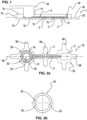
- FIG. 1 The structure of a sensor arrangement 1 according to the invention for the non-invasive measurement of parameters of a body tissue with a sensor unit 10 and a sensor mat 12 for the detachable application of the sensor arrangement 1 on a body surface 20 is shown schematically.
- the sensor arrangement 1 essentially comprises the reusable sensor unit 10, the sensor mat 12, and a contact head 16 for electrically and optically contacting the sensor arrangement 1.
- the sensor unit 10 has light detector devices 2, also referred to as measuring surfaces 2, and conductor tracks 5, spaced from the position of the contact head 16. Further elements, for example, control units, can be provided in the sensor arrangement 1. From a light source, light with different wavelengths in the near-infrared range (NIRS) for measuring parameters can be emitted, preferably staggered in time, via the contact head 16 or via a light source arranged directly on the sensor unit 10 or in the contact head 16 and comprising several light-emitting or laser diodes, preferably four laser diodes.
- NIRS near-infrared range
- Photodiodes for example, are used as sensor surfaces 2.
- the sensor unit 10 is designed along a longitudinal axis 18 in an elongated, flat body shape, with a A defined outer contour, which is adapted to the outer contour of the enclosed elements and to the body surface to be applied.
- the sensor unit 10 is designed as a flexible printed circuit board and is therefore bendable to a certain extent.
- the sensor unit 10 is mounted on the sensor mat 12, which comprises a lower layer 13 and an upper layer 14.
- the lower layer 13 has a base surface on its underside with a plurality of cutouts 15, which provide a passage for light.
- the base surface faces the body surface 20.
- the underside of the base surface is designed as a support surface for resting on the body surface 20.
- the base surface completely surrounds the sensor unit 10 and its outer contour is matched to the sensor unit 10, with wings being provided in particular, which are arranged largely perpendicular to both sides of the longitudinal axis 18.
- the shape of the sensor mat 12 determines the size of the support surface and thus the support on the body surface 20 for fastening the sensor arrangement 1.
- An adhesive layer is arranged on the support surface of the lower layer 13.
- the upper side of the lower layer 13 is in contact with the upper layer 14 of the multi-layer sensor mat 12.
- the lower layer 13 and the upper layer 14 are releasably connected to one another at the contact surface, for example, by an adhesive layer.
- the upper layer 14 also has an opening 17 through which the contact head 16 is at least partially guided. Accordingly, the upper layer 14 of the sensor mat 12 covers the sensor unit 10 as a cover.
- the sensor mat 12 is flexible in order to be able to adapt to the contour of the body surface 20.
- the sensor mat 12 is intended as a disposable unit and is disposed of after a single use.
- the multi-layer sensor mat 12 has at least one foam layer.
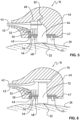
- FIG. 2a A schematic plan view of the sensor unit 10 is shown, which is designed as a flexible or rigid-flexible printed circuit board.
- the sensor unit 10 is in the form of a flat body, wherein first and second light detector devices 2, or sensor surfaces 2, are arranged.
- the light detector devices 2 are positioned at different separation distances from a light coupling point to a contact surface 22, or light exit surface or light coupling point. The separation distance depends on the circumstances of the application and, in the illustrated embodiment, refers to light detector devices 2 for measuring in body surfaces 20 near and deeper body tissues.
- Conductor tracks 5 extend along the longitudinal axis 18, which are configured both for signal conduction and for electrical contacting and a first contact means 30 with a contact geometry 32 and.
- the first contact means 30 is formed in a largely annular, integral manner on the sensor unit 10, which is designed as a flexible or rigid-flexible printed circuit board. Positioning elements 31 are provided in one or more regions on an outer circumference of the largely annular first contact means 30, for example in the form of indentations on the circumference.
- the shape of the annular first contact means 30 is complementary to the shape of a positioning ring 33, which is Figure 2b is shown.
- the positioning ring 33 has, on an inner circumference, correspondingly designed positioning elements 35, for example protuberances, which allow the positioning ring 33 to be positioned and fixed in a predetermined orientation on the sensor unit 10.
- the positioning ring 33 allows the contact head 16 to be contacted with the sensor unit 10 to be positioned in a predetermined orientation by the shape of the positioning ring 33.
- Magnetic contact elements 34 and electrical contact elements 36 are arranged on an annular surface of the first contact means 30 in an arrangement according to the contact geometry 32.
- the electrical contact elements 36 can be electrically conductively contacted via the conductor tracks 5 to activate the light detector devices 2.
- the magnetic contact elements 34, with a corresponding counterpart provided on the contact head 16, form a detachable connection between the sensor unit 10 and the contact head 16, as will be described later.
- the magnetic coupling provides the electrical contact of the sensor unit 10.
- Figure 3 1 shows a plan view of the sensor mat 12 viewed from below, so that the base area of the lower layer 13 is visible.
- the sensor mat 12 is designed as an elongated, flat body which extends in particular along the longitudinal axis 18.
- the base area which forms the support surface for resting on the body surface 20, has a plurality of recesses 15 in the regions where optical components of the sensor unit 10 are provided, for example the light coupling point 22 and the light detector devices 2.
- the outer contour of the sensor mat 12 can have different shapes; in particular, wings can be provided in regions of the optical components, which wings are generally designated 24 and which extend at least partially perpendicular to the longitudinal axis 18.
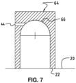
- FIG. 7 An embodiment of a deflecting element 64 is shown.
- the deflecting element 64 is designed as a separate element that can be received in the contact head 16 and fixed therein.
- the deflecting element 62 is designed as a hollow cylinder with a hemispherically closed end 66.
- a receptacle for the fiber optic 44 opens into this hemispherical end 66, so that light emerging from the fiber optic 44 is reflected by the hemispherical shape and deflected essentially perpendicular to the fiber optic 44 in order to emit from the light coupling point 22 or the contact surface 22 into the body surface 20 in contact therewith.
Landscapes
- Physics & Mathematics (AREA)
- Life Sciences & Earth Sciences (AREA)
- Health & Medical Sciences (AREA)
- Spectroscopy & Molecular Physics (AREA)
- Optics & Photonics (AREA)
- Heart & Thoracic Surgery (AREA)
- Molecular Biology (AREA)
- Pathology (AREA)
- Engineering & Computer Science (AREA)
- Biomedical Technology (AREA)
- Veterinary Medicine (AREA)
- Medical Informatics (AREA)
- Biophysics (AREA)
- Surgery (AREA)
- Animal Behavior & Ethology (AREA)
- General Health & Medical Sciences (AREA)
- Public Health (AREA)
- General Physics & Mathematics (AREA)
- Measurement Of The Respiration, Hearing Ability, Form, And Blood Characteristics Of Living Organisms (AREA)
- Investigating Or Analysing Materials By Optical Means (AREA)
Description
- Die vorliegende Erfindung bezieht sich auf eine Sensoranordnung, insbesondere eine Sensoranordnung zur nicht-invasiven Messung von Körperparametern, beispielsweise zerebralen Parametern wie den Sauerstoffgehalt des Gehirns.
- Es ist bekannt, dass zur Messung von Körperparametern, insbesondere von zerebralen Parametern wie Konzentrationen von desoxygeniertem und oxygeniertem Hämoglobin des zerebralen Blutflusses oder des Gewebesauerstoffindexes, eine Messvorrichtung auf eine Körperoberfläche, z.B. eine Kopfoberfläche, angeordnet und eine Messung mittels Nahinfrarotspektroskopie (NIRS) durchgeführt wird.
- Demnach kann durch Verwendung von Lichtquellen, welche Nahinfrarotlicht bei bestimmten unterschiedlichen Wellenlängen übertragen, und durch Messung von Änderungen der Extinktion detektierten oder reflektierten Lichts, Änderungen der Sauerstoffkonzentration von desoxygeniertem und oxygeniertem Hämoglobin überwacht werden. Mittels eines anderen spektrophotometrischen Verfahrens, der sogenannten Pulsoximetrie, ist durch Überwachung der pulsatilen optischen Extinktionsänderungen des detektierten Lichts, die arterielle Sauerstoffsättigung im peripheren Gewebe, beispielsweise Finger, Ohr, Nase, bestimmbar.
- Es sind NIRS-Überwachungsanordnungen zur nicht-invasiven Überwachung, beispielsweise des Blutsauerstoffgehalts, bekannt, welche wiederverwertbare und zu entsorgende Komponenten umfassen. So ist zum Beispiel aus
WO 94/27494 - Aus
EP 2 916 716 ist eine nicht-invasive Messvorrichtung zur Messung von Parametern eines Körpergewebes bekannt, welche eine Sensoreinheit und eine Sensormatte zum lösbaren Aufbringen auf einer Körperpartie bereitstellt. Die Sensoreinheit umfasst eine in einer Aufnahme aufgenommene Sensoranordnung mit einer an einer Unterseite in Richtung Körperoberfläche orientierten Sensorfläche, wobei die Sensoreinheit mittels eines Deckels oder einer Folie lichtdicht verschlossen wird. Die Aufnahme ist in einer an der biegsamen und/oder komprimierbaren Sensormatte ausgebildeten entsprechenden Aussparung aufgenommen, wobei die Sensormatte mit einer Auflagefläche auf der Körperoberfläche aufliegt und mittels einer Haftlage mit dieser verbindbar ist. Sensoreinheit, Sensormatte und Abdeckung sind lösbar miteinander verbunden, wobei Sensormatte und Abdeckung Einweg-Produkte sein können. Demnach umfasst die Sensoreinheit eine Sensoranordnung, aufgenommen in einer nur teilweise flexiblen Aufnahme, welche als eine Art flaches Gehäuse oder Schale ausgebildet ist, d.h. eine Grundfläche und eine Umfangswandung umfasst. Die Sensoranordnung weist eine daran angeordnete und fest mit dieser verbundenen Kontakteinheit für die Zu- und Ableitung elektrischer und optischer Signale, die Stromversorgung und die Verbindung mit einer externen Steuer- und Verarbeitungseinheit und/oder Kontrolleinheit auf. - Aus
WO 2012/109661 ist eine NIRS-Sensoranordnung bekannt, welche einen Sensorteil mit einer Lichtquelle, beispielsweise eine Kombination aus faseroptischen Lichtleiter und Prisma und mindestens einem Lichtdetektor aufweist, ebenso wie eine flexible elektrische Schaltung und ein Verbinderelement. Die flexible elektrische Schaltung kann mehrschichtig sein und umfasst in einer Kommunikationsschicht mehrere Leiterbahnen und eine EMI-Abschirmung zur elektrischen Kontaktierung und Signalübertragung der Sensoranordnung mit dem Verbinderelement. Das Verbinderelement umfasst einen Faseroptik-Koppler als optische Schnittstelle und einen Leitungskoppler als elektrische Schnittstelle, wobei beide beispielsweise in einem Hybridverbinder zusammengefasst sein können. Eine lösbare Verbindung mittels Kontaktelementen eines derartigen Hybridverbinders an der Sensoranordnung wird nicht beschrieben. - Aus
US 2009/182209 ist eine NIRS-Sensoranordnung bekannt, wobei von einer Lichtquelle mittels eines faseroptischen Lichtleiters und einem an der Sensoranordnung aufgenommenes, in einem Gehäuse angeordnetes Prisma Licht in eine Körpergewebe emittiert wird. Ferner erfolgt eine elektrische Kontaktierung der an einer flexiblen Schaltung angeordneten Lichtdetektoren der Sensoranordnung mittels eines abgeschirmten Kabels, welches auch unabhängig von der optischen Kontaktierung an der Sensoranordnung angeordnet sein kann. Die Kombination aus Lichtleiter und Prisma ist zwar drehbar an der Sensoranordnung angeordnet aber nicht mit dieser lösbar verbindbar. - Aus
US 2017/319132 ist ein tragbares Kleidungsstück mit daran angeordneten Sensoren bekannt, welche eine Kommunikation mit einem tragbaren Telefon ermöglichen. -
US 2016/029890 beschreibt ein System zur automatisierten Triage-Priorisierung, umfassend eine tragbare Einrichtung mit einer Vielzahl von Sensoren zur Erfassung von physiologischen, physikalischen und Umgebungsparametern. Demnach ist auch ein Pulsoximetriesensor vorgesehen mit Lichtemitter und Lichtdetektor, wobei die Einrichtung mittels vorgesehener Komponenten auf der Oberfläche in einer bestimmbaren Position angeordnet werden kann. -
US 6,014,576 beschreibt eine zweiteilige Sonde mit einem universellen Sondenende und einem Verbindungskabelsegment, welches mit einer Vielzahl von verschiedenen photoplethysmographischen Geräten verwendet werden kann. Das Stecker-Ende des Verbindungskabelsegments ist jedoch starr, und kann nur in einer vorgegebenen Richtung in das Sondenende eingesteckt werden. Dadurch ist die Anbringung auf flache Körperoberflächen limitiert. - Aus dem Stand der Technik sind Messanordnungen bekannt, welche aufgrund einer mehr oder weniger starren Aufnahme für eine Sensoreinheit nicht über eine gewünschte Flexibilität verfügen, um auch an stark gekrümmten Körperflächen angeordnet werden zu können. Ferner ist auch die operative Kontaktierung der umfassten Sensoreinheit nicht unabhängig von der Messanordnung gelöst.
- Es ist Aufgabe der vorliegenden Erfindung eine nicht-invasive Sensoranordnung zur Bestimmung von Körperparametern, bzw. Parametern des Körpergewebes, bereit zu stellen, bei welcher die Herstellungskosten gesenkt, die Flexibilität der Anordnung erhöht und die operative Kontaktierung unabhängig gestaltet ist. Da bei der Höhe der Herstellungskosten auch die Wiederverwertbarkeit zumindest einzelner Komponenten zu berücksichtigen ist, wird mit der Erfindung angestrebt, insbesondere teure Komponenten wiederverwertbar auszubilden. Insbesondere soll ein homogener Kontakt zwischen Sensoranordnung und Oberfläche des Körpergewebes sichergestellt und die Sensoranordnung zumindest teilweise wiederverwendbar sein.
- Diese und weitere Aufgaben werden von einer nicht-invasiven Sensoranordnung gemäss dem unabhängigen Patentanspruch gelöst. Besondere Ausgestaltungen und/oder Varianten gehen aus den abhängigen Ansprüchen hervor.
- Gemäss der Erfindung weist eine Sensoranordnung zur nicht-invasiven Messung von Parametern eine Sensoreinheit und eine Sensormatte zum lösbaren Aufbringen, bzw. zum Befestigen, der Sensoranordnung auf einer mehr oder weniger gekrümmten Körperoberfläche auf. Die Sensoranordnung umfasst einen Kontaktkopf, welcher mit der Sensoreinheit verbindbar ist, und welcher zum elektrischen Kontaktieren der Sensoreinheit und zum Zuführen von Licht von einer Lichtquelle zu der Sensoreinheit ausgebildet ist. Ferner ist die Sensoreinheit als eine flexible Leiterplatte ausgebildet mit optischen Komponenten, welche mindestens eine Lichtdetektoreinrichtung umfassen, um Licht zu detektieren, welches von dem an der Sensoreinheit aufgenommenen und verbundenen Kontaktkopf in das Körpergewebe emittiert und dieses passiert hat, sowie einem ersten Kontaktmittel und Leiterbahnen zum operativen Verbinden der Sensoreinheit mit dem Kontaktkopf. Die Sensoreinheit ist zudem als entlang einer Längsachse gestreckter Körper mit Laschen ausgebildet, welche im Wesentlichen senkrecht zur und/oder entlang der Längsachse ausgebildet sind. Hierbei sind an dem langgestreckten Körper der Sensoreinheit im Bereich der optischen Komponenten, bzw. der Lichtdetektoreinrichtung, Laschen ausgebildet, welche sich senkrecht und/oder entlang der Längsachse erstrecken. Die Sensormatte der erfindungsgemässen Sensoranordnung hat einen mehrschichtigen Aufbau, mit einer unteren Schicht, welche eine untere Auflagefläche zur Auflage auf der Körperoberfläche und eine obere Auflagefläche zur Auflage der Sensoreinheit aufweist, wobei Aussparungen vorgesehen sind, welche auf die optischen Komponenten der Sensoreinheit abgestimmt sind, und einen optischen Durchgang bilden. An einer Unterseite der unteren Schicht und damit der Körperoberfläche zugewandt kann ferner zumindest eine weitere Schicht angeordnet sein, welche in den Bereichen der Aussparungen optisch transparente Abschnitte aufweist und demnach eine Art Folienfenster in Bezug zu den Lichteinkopplungs- bzw. Lichtauskopplungsabschnitten bildet. Optisch transparent bedeutet, dass durch eine derartige Schicht eine Lichtmenge treten kann, welche beispielsweise für eine NIRS-Analyse ausreichend ist. Andere Bereiche der Schicht können dagegen optisch nicht transparent sein. Alternativ können eine erste optisch transparente Schicht und eine weitere optisch nicht transparente Schicht mit entsprechenden optischen Durchgängen an der Unterseite der unteren Schicht der Sensormatte angeordnet sein. Die optisch nicht transparenten Abschnitte, bzw. die optisch nicht transparente weitere Schicht, stellen eine Art Isolierschicht bereit, welche zwischen den optisch aktiven Bereichen der Sensoranordnung angeordnet sind und demnach eine Beeinflussung der Lichtdetektion durch beispielsweise seitlichen Lichteinfall und/oder Hintergrundlicht verhindern. Eine derartige Abdeckung der optisch aktiven Komponenten wirkt sich vorteilhaft im Hinblick auf eine sterile Sensoranordnung aus. Ferner umfasst die Sensormatte eine obere Schicht, welche mit der oberen Auflagefläche der unteren Schicht voneinander lösbar verbunden ist. Eine Aussenform der Sensoranordnung ist mit Einkerbungen bzw. Einschnitten gestaltet, so dass diese an unterschiedlichsten Körperoberflächen anordenbar ist und insbesondere einen guten Tragekomfort bietet.
- Die Sensoranordnung besteht aus voneinander trennbaren Komponenten, wobei der Kontaktkopf und die Sensoreinheit eine operative Verbindung eingehen und die Sensormatte ausgebildet ist, um die damit verbundene Sensoreinheit leicht und sicher an der Haut einer zu untersuchenden Person zu befestigen. Es ist wirtschaftlicher, die Sensoreinheit und/oder den Kontaktkopf als wiederverwendbare Elemente zu gestalten, während gleichzeitig die hohen Anforderungen an Hygiene und Sterilisation bei der Anwendung im Gesundheitswesen erfüllt werden. Die Sensoreinheit ist demnach in der mehrschichtigen Sensormatte aufnehmbar, deren einzelne Schichten voneinander trennbar sind, so dass die dazwischen aufgenommene Sensoreinheit entnommen und nach vorbereitenden Schritten wieder verwendet werden kann.
- Die Sensoreinheit einer derartigen optoelektronischen Sensoranordnung ist gemäss der Erfindung als flexible oder starr-flexible Leiterplatte ausgebildet, auch bezeichnet als Flexprint. An der Sensoreinheit können Ausgänge einer oder mehrerer Lichtquellen, wie etwa Leuchtdioden, Laserdioden oder eine oder mehrere Lichtquellen selbst angeordnet sein und davon beabstandet eine oder mehrere Sensorflächen, z.B. als Fotodioden ausgebildete Lichtdetektoren, ebenso wie elektrische Leitungen, die z.B. Licht der Lichtquelle oder der Lichtquellen oder elektrische Signale von und zu den Elementen der Sensoreinheit leiten. Ebenfalls können weitere Elemente vorgesehen sein, beispielsweise eine Kontrolleinheit, welche über entsprechend vorgesehenen Sensorflächen eine Hintergrundbeleuchtung jeweils zwischen einzelnen Lichtpulsen der Lichtquelle misst und/oder den elektrischen Strom. Demnach kann die Kontrolleinheit über die Sensorflächen automatisch eine Hintergrundbeleuchtung jeweils zwischen Laserlichtpulsen messen, ausgehend von der Lichtquelle, welches als Korrektur des gemessenen Lichts während der Laserlichtimpulse genutzt wird. Bei einer teilweise oder vollständig abgelösten Sensoranordnung verändert sich die Hintergrundbeleuchtung, so dass entweder ein Störsignal oder eine Störautomatik erzeugt werden kann, welche zur automatischen Abschaltung der Leucht- bzw. Laserdioden führen kann. Ferner kann die Kontrolleinheit für weitere Kalibrierungs- und Messaufgaben verwendet werden.
- Als Ergänzung kann ferner ein Mittel zur Erfassung von Temperatur und/oder Wärmefluss vorgesehen sein. Beispielsweise kann vorgesehen sein, die Temperatur des zu untersuchenden Gewebes mittels NIRS zu ermitteln, welches auf einer Temperaturabhängigkeit des Wasserabsorptionsspektrums basiert. Ferner kann aber auch eine der umfassten Sensorflächen verwendet werden, um die Temperatur einer in der Sensoranordnung integrierten Lichtquelle zu erfassen zur Verifizierung des Temperatureinflusses auf die Emissionscharakteristiken der Lichtquelle, z.B. der LED's, und der ermittelten Messergebnisse. Es ist bekannt, dass Wärme von einer nahe an der Körperoberfläche positionierten Lichtquelle von einem Patienten als unangenehm empfunden wird, bzw. bei zu hoher Temperatur es sogar zu einem Ausfall einzelner Komponenten der Sensoranordnung kommen kann.
- Vorzugsweise werden als Lichtquelle wenigstens vier verschiedene Leucht- bzw. Laserdioden unterschiedlicher Wellenlänge vorgesehen, die zeitlich gestaffelt ein- und ausgeschaltet werden können. Die Lichtquelle ist selektiv betreibbar, um insbesondere infrarotes Licht zu leiten oder zu emittieren, wobei die Lichtquelle entweder als eine in der Sensoranordnung integrierte Lichtquelle selbst Lichtsignale erzeugt oder Lichtsignale an einer Position ausserhalb der Sensoranordnung erzeugt und mittels einer Faseroptik der Sensoranordnung zugeführt werden. So können eine oder mehrere Lichtquellen, ausgebildet als Leuchtdioden oder Laserdioden, in dem Kontaktkopf direkt integriert sein, so dass Verluste der Leuchtdichte an optischen Kopplungsstellen vermieden werden. Diese integrierten Lichtquellen werden als interne Lichtquellen bezeichnet.
- Übertragungsverluste werden weitgehend vermieden, wenn von einer entfernten Lichtquelle das Licht mittels Faseroptik via dem Kontaktkopf in das zu untersuchende Körpergewebe emittiert wird. Insbesondere bei einer ausserhalb der Sensoranordnung positionierten Lichtquelle, d.h. einer externen Lichtquelle, wird vorteilhaft vermieden, dass es zu einer Beeinflussung des Untersuchungsraums bzw. des Blutflusses durch Wärmeentwicklung der Lichtquelle kommen kann.
- Die Lichtdetektoren, insbesondere die eine oder mehrere Fotodioden, sind an der Sensoreinheit angeordnet, so dass dieser von der Lichteinkopplungsstelle, um einige mm bis mehr als 20 mm getrennt ist. Vorzugsweise beträgt ein Abstand von der Lichteinkopplungsstelle zu mindestens einer ersten Fotodiode, bezeichnet als Nahdetektoren, etwa 20 mm und zu einer oder mehreren weiteren zweiten Fotodioden etwa 40 mm, welche als Ferndetektoren bezeichnet sein können. Dabei können sich die relative Position und der Abstand der Lichtdetektoren von der oder den Lichteinkopplungsstellen nach der Grösse des zu untersuchenden Objekts richten. Die Anzahl der Fotodioden können in den Lichtdetektoren je nach Anwendung variieren. Mehrere Fotodioden können verwendet werden, um verschiedene Tiefen der Blutoxygenierung in dem Subjekt zu überwachen, oder können als Referenzdetektoren verwendet werden, beispielsweise um in einem Algorithmus Störeffekte der detektierten Signale zu kompensieren.
- In Bezug auf die Sensoreinheit wird als Flexprint allgemein eine flexible oder starr flexible Leiterplatte mit gedruckten Leiterbahnen mit einem Substrat aus einem isolierenden Polymermaterial mit daran angeordneten bzw. eingebetteten Fasern aus einem elektrisch leitenden Material zur Ausbildung einer flexiblen Schaltung bezeichnet. Eine flexible Schaltung in Zusammenhang mit einem flexiblen Substrat verbessert die Flexibilität einer derartigen Sensoreinheit. Die als flexible Leiterplatte ausgebildete Sensoreinheit kann mehrschichtig aufgebaut sein, insbesondere mit einer Kommunikationsschicht, beispielsweise umfassend ein flexibles kupferkaschiertes Laminat, sowie mit Deckschichten bzw. Isolierschichten und entsprechenden Klebeschichten ausgebildet sein. Die mehreren Schichten der Sensoreinheit können laminiert, zusammengefügt oder auf andere Weise miteinander verbunden sein, um eine einzige Struktur zu bilden. Die Anzahl der Schichten kann ebenfalls variieren. Beispielsweise können eine oder mehrere Schichten optisch transparente Abschnitte zumindest in Ausrichtung zu den Bereichen der Lichteinkopplungsstelle und der Lichtdetektorflächen aufweisen, durch welche eine Lichtmenge hindurchtreten können. Zum Beispiel kann der optisch transparente Abschnitt ein elektrisch leitendes Drahtgeflecht, z.B. ein Kupferdrahtgeflecht, enthalten. Andere Abschnitte der Sensoreinheit sind optisch nicht transparent und können beispielswiese aus einer Kupfermetallfolie gebildet sein. Eine derartig ausgebildete Sensoreinheit zeichnet sich durch ein geringes Gewicht und Volumen aus, bietet eine hohe Designfreiheit und dynamische und mechanische Belastbarkeit.
- In einer Ausführungsform sind zumindest abschnittsweise an der Sensoreinheit Verstärkungselemente vorgesehen. Diese auch als Stiffener bezeichnete Verstärkungselemente können als Formstücke aus einen starren Material ausgebildet sein, insbesondere in Form von Polymerverdickungen, die in gewünschten Bereichen, beispielsweise im Bereich der Fotodioden, die flexible Leiterplatte versteifen. Zur weiteren Stabilisierung der Form und der Planheit der Sensoreinheit kann ein Kupfernetz als Flechtschicht vorgesehen sein. Das vorgesehene Kupfernetz kann auch eine Art Abschirmung gegen elektromagnetische Interferenzen bereitstellen.
- Die Sensoreinheit ist als ein sich entlang einer Längsachse erstreckender Körper ausgebildet. Die Formgebung der Sensoreinheit berücksichtigt abgerundete Übergänge und entsprechend geformte Abschnitte, so dass Bruchstellen vermieden werden, wenn die Sensoreinheit in einer starken Krümmung oder stark gebogen angeordnet wird, beispielsweise um einen Finger gelegt ist.
- Die als langgestreckter Körper ausgebildete Sensoreinheit weist Laschen auf, welche sich im Wesentlichen senkrecht zu beiden Seiten und/oder entlang der Längsachse des Körpers erstrecken. Die Laschen, auch als Nasen bezeichnet, sowie die grundsätzliche Formgebung des Körpers der Sensoreinheit erlauben seine plane Auflagefläche auf der Sensormatte. Hierbei liegen die optischen Komponenten, d.h. Lichtdetektoreinrichtungen und/oder Emitter, beispielsweise auf optisch transparenten Flächen bzw. Fenstern der Sensormatte oder direkt an der Körperoberfläche für eine effiziente Messung auf. Mit der erfindungsgemässen Ausgestaltung der Sensoreinheit ist es nicht erforderlich, dass die Sensoreinheit in einer mehr oder weniger starren Aufnahme aufgenommen und darin mittels Silikonguss fixiert wird, um dann an oder in einer Sensormatte aufgenommen zu werden. Die Flexibiltät erhöht sich dementsprechend.
- Gemäss einer Ausführungsform umfasst die Sensoreinheit die ersten Kontaktmittel mit einer Kontaktgeometrie, welche zum elektrischen Kontaktieren und zum Verbinden mit dem Kontaktkopf ausgebildet ist. Demnach stellt das erste Kontaktmittel eine operative Verbindung zur elektrischen Versorgung der Sensoreinheit und zur Verbindung mit einer Lichtquelle bereit, ebenso wie zur Übermittlung von detektierten Signalen. Mit anderen Worten ist das erste Kontaktmittel ein Kopplungselement bzw. ein Steckerelement, welches mit einem entsprechend ausgebildeten Gegenstück lösbar verbunden werden kann. Die Verbindung kann unteranderem als Steckkontakt oder Rastung ausgebildet sein. In einer bevorzugten Ausführungsform umfasst die Kontaktgeometrie hierfür magnetische und elektrische Kontaktelemente. So kann das erste Kontaktmittel als ein Kontaktring ausgebildet sein, welcher an der als flexible oder starr-flexible Leiterplatte ausgebildete Sensoreinheit in einer Position ausgebildet ist, welche geeignet ist, um mit dem noch näher zu erläuternden Kontaktkopf in Kontakt gebracht zu werden. Insbesondere kann der Kontaktring die Form eines PCB-Rings haben, umfassend eine Vielzahl von Elementen zur elektrischen und mechanischen bzw. magnetischen Kontaktierung mit entsprechenden an dem Kontaktkopf vorgesehenen Gegenstücken. Dabei ist vorgesehen, dass der verbindbare Kontaktkopf in einer vorbestimmbaren Orientierung relativ zur Sensoreinheit positionierbar ist. Insbesondere kann eine Ausrichtungshilfe, beispielsweise in Form eines Positionierrings, an dem Kontaktring angeordnet sein, welcher durch eine asymmetrische Formgebung bzw. Formabschnitten eine vorbestimmte Ausrichtung des verbindbaren Kontaktkopfes vorgibt. So können Kabel, welche zur elektrischen und/oder optischen Verbindung an dem Kontaktkopf verbunden sind, in einer Orientierung ausgerichtet werden, dass eine Person durch die befestigte Sensoranordnung nicht gestört wird. Insbesondere kann der Positionierring mit der Sensoreinheit verklebt sein.
- Das erste Kontaktmittel weist die Kontaktgeometrie auf, umfassend elektrische und magnetische Kontaktelemente. Insbesondere können die Kontaktelemente auf einem Kontaktring zusammengefasst sein, wobei die Kontaktgeometrie auf einer Ringfläche in einer Anordnung vorgesehen ist, so dass beispielsweise mehrere elektrische Kontaktelemente, insbesondere Kontaktpunkte, zur elektrischen Kontaktierung der Sensorflächen, d.h. der Fotodioden der Nah- und/oder Ferndetektoren und ein oder mehrere magnetisch wirksame Kontaktelemente vorhanden sind. Die magnetisch wirksamen Kontaktelemente können als Weissblechpunkte ausgebildet sein. Vorzugsweise sind elektrische und magnetische Kontaktelementen in einer sich gegenseitig abwechselnden Reihenfolge positioniert, d.h. dass ein elektrisches Kontaktelement zwischen benachbarten magnetischen Kontaktelementen liegt. Hiermit wird eine gegenseitige Beeinflussung elektrischer Kontaktelemente vermieden. Die magnetischen Kontaktelemente sind so ausgewählt, dass eine sichere Kontaktierung zwischen Sensoreinheit und Kontaktkopf vorliegt. Ferner kann vorgesehen sein, dass die sichere Kontaktierung von Sensoreinheit und Kontaktkopf mittels entsprechender Erfassungsmittel bzw. Kontrollmittel detektiert und angezeigt wird.
- Die Sensoreinheit der erfindungsgemässen Sensoranordnung kann in einfacher Weise hergestellt werden, in dem vorgefertigte Bauteile lediglich zueinander in Verbindung gebracht werden müssen, vorzugsweise durch "pick und place"-Schritte.
- Die Sensoreinheit und der damit operativ verbindbare Kontaktkopf können mit der Sensormatte lösbar verbunden werden. Die Sensormatte weist Ausnehmungen, bzw. Öffnungen, oder transparente Fenster auf, die entsprechend der optischen Komponenten der Sensoreinheit, d.h. Lichtdetektoreinrichtung und/oder Emitter, angeordnet und ausgebildet sind. Grundsätzlich ist die Sensormatte als eine längliche flache Matte ausgebildet, mit einem mehrschichtigen Aufbau, wobei beispielsweise mindestens eine Schaumschicht aus einem dünnen, biokompatiblen Schaummaterial mit einer bzw. beidseitig angeordneter Klebeschicht umfasst ist.
- Hierbei ist eine untere Schicht umfasst, welche Öffnungen bzw. Durchgänge oder auch transparente Fenster im Bereich der Sensorflächen, d.h. der Fotodioden, und dem Einkopplungsbereich, bzw. der Lichtaustrittsfläche des Lichts, d.h. dem Emitter, aufweist und welche mit einer Unterseite mit einer Körperoberfläche in Kontakt steht und an dieser mittels eine Klebeschicht aufbringbar ist. Die entsprechende Oberseite ist ebenfalls klebend, so dass die darauf aufliegende Sensoreinheit insbesondere mittels der daran ausgebildeten Laschen bzw. Nasen gehalten ist. Desweiteren ist mindestens eine weitere Schicht, d.h. eine obere Schicht, umfasst, welche nur eine Aussparung im Bereich der Lichteinkopplung, d.h. im Bereich des Kontaktkopfes, aufweist. Die obere Schicht umfasst eine untere Klebschicht, welche mit der Oberseite der unteren Schicht in einer haftenden Verbindung steht, so dass dazwischen die Sensoreinheit positionssicher aufgenommen ist. Die mehrschichtige Sensormatte kann als Einweg-Einheit ausgebildet sein, d.h. nach einer Messung kann die Sensoranordnung von der Körperoberfläche entfernt und die einzelnen Komponenten, d.h. Sensoreinheit, Sensormatte und Kontaktkopf, voneinander getrennt und die Sensormatte entsorgt bzw. wieder aufbereitet werden.
- Vorzugsweise ist die Sensormatte flexibel, bzw. biegsam ausgebildet, so dass die Sensormatte an die Körperoberfläche anpassbar ist und sich an Krümmungen, Erhebungen oder Vertiefungen derselben anpasst. Die Gestaltung der Sensormatte sieht einen Aussenumfang vor, welcher beispielsweise Einkerbungen und/oder Dünnstellen aufweist, welche entlang des gesamten Aussenumfangs vorgesehen sind. Insbesondere kann der Aussenumfang an den Bereichen, an denen die Laschen bzw. Nasen der Sensoreinheit an der Sensormatte zu liegen kommen, in Form von Flügeln ausgebildet sein, so dass eine leichte Anpassung der Sensormatte an die Kontur der Körperfläche ermöglicht wird.
- In einer alternativen Ausführungsform der Sensormatte kann zwischen der unteren Schicht und der oberen Schicht eine mittlere Schicht vorgesehen sein.
- Zur Messung von Körperparametern wird in einer Ausführungsform die Sensoranordnung dadurch aktiviert, dass mittels des mit der Sensoreinheit verbundenen Kontaktkopfes eine Einkopplung von Lichtwellen und eine elektrische Kontaktierung erfolgen. Der mit der Sensoreinheit verbindbare Kontaktkopf umfasst ein Gehäuse, mindestens zweite Kontaktmittel, welche eine Kontaktgeometrie entsprechend dem ersten Kontaktmittel der Sensoreinheit aufweisen, elektrische Leitungen, welche in dem Gehäuse fixierbar und welche mit elektrischen Kontaktelementen der zweiten Kontaktmittel leitend verbindbar sind. Der Kontaktkopf umfasst Mittel zum Bereitstellen und Führen von Licht in einer Richtung, welche senkrecht zur Körperoberfläche gerichtet ist und eine Lichtaustrittsfläche, über die Licht in das Körpergewebe emittiert. In einer Ausführungsform umfassen die Mittel eine Faseroptik, um Licht von einer externen Lichtquelle zuführen und ein Umlenkelement, um das in einer Richtung zugeführte Licht in die Richtung senkrecht zur Körperoberfläche umzulenken. Das Umlenkelement kann eine Reflexionsfläche bereitstellen, um das zugeführte Licht aus einer ersten Richtung in eine zweite Richtung umzulenken, welche im Wesentlichen senkrecht zu der Körperoberfläche gerichtet ist, und via einer Lichtaustrittsfläche in das Körpergewebe emittiert.
- In einer alternativen Ausführungsform ist vorgesehen, dass die Mittel zum Bereitstellen und Führen von Licht eine interne Lichtquelle umfassen, beispielsweise in Form von einer oder mehrerer Leucht- bzw. Laserdioden, welche in dem Kontaktkopf selbst als interne Lichtquelle integriert ist, und ein Lichtleitelement, so dass davon ausgehendes Licht in Richtung senkrecht zur Körperoberfläche gelenkt wird und über eine Lichtaustrittsfläche emittiert. Demnach ist in einer derartigen Ausführungsform keine Faseroptik erforderlich, sondern die von der internen Lichtquelle ausgehenden Lichtwellen werden mittels des Lichtleitelements via der Lichtaustrittsfläche in das damit in Kontakt stehende Körpergewebe emittiert.
- Ferner kann vorgesehen sein, dass zur elektrischen Kontaktierung der in dem Kontaktkopf integrierten internen Lichtquelle und/oder der mit dem Kontaktkopf verbindbaren Sensoreinheit eine in dem Kontaktkopf aufgenommene Energiequelle vorgesehen ist, so dass die elektrischen Leitungen innerhalb des Kontaktkopfes verlaufen zur elektrischen Kontaktierung der mindestens einen Lichtdetektoreinrichtung der Sensoranordnung, während keine externen Verbindungen erforderlich sind. Eine Übertragung der Signale, d.h. eine Datenübertragung, von der mindestens einen Lichtdetektoreinrichtungen und/oder Kontrolleinheit zu einer externen Steuer- und/oder Verarbeitungseinheit kann mittels drahtloser Kommunikation erfolgen.
- Vorgesehene Kontrollmittel stellen sicher, dass kein Licht emittiert wird, wenn kein Kontakt zu einer Körperoberfläche besteht, bzw. wenn der Kontaktkopf nicht sicher mit der Sensoreinheit verbunden ist. Hierfür sind Kontrollmittel vorgesehen, um eine Hintergrundbeleuchtung zu messen, wobei die Messung der Hintergrundbeleuchtung genutzt wird, um eine Not-Ausschaltung der Sensoranordnung zu realisieren. Sobald der Wert bzw. die Intensität der Hintergrundbeleuchtung einen vorbestimmten Maximalwert überschreitet, werden die eine oder mehreren Lichtquellen ausgeschaltet, um sicherzugehen, das keine Gefahr besteht, falls die Sensoranordnung sich teilweise oder vollständig von der Körperoberfläche absichtlich oder unabsichtlich gelöst hat.
- Die elektrischen Leitungen und die Zuführungen von Licht, z.B. als Faseroptik mit mindestens einer optischen Faser ausgebildet, können in einem Hybridkabel zusammengefasst sein, welches an dem Kontaktkopf fixierbar ist.
- Zur elektrischen Kontaktierung der Sensoreinheit der erfindungsgemässen Sensoranordnung sind die zweiten Kontaktmittel vorgesehen, welche in dem Gehäuse des Kontaktkopfes als separate ringförmige Komponenten aufnehmbar sind. Die zweiten Kontaktmittel umfassen in einer Ausführungsform einen ersten Kontaktring, an welchem auf einer ersten Seite Federkontaktstifte in einer vorgegebenen Anordnung und auf einer zweiten Seite Steckerelemente angeordnet sind, welche mit einem an den elektrischen Leitungen vorgesehenen Gegenstück einen Steckerkontakt bilden, und einen zweiten Kontaktring, welcher Durchgangsbohrungen aufweist, durch welche sich die Federkontaktstifte erstrecken und an welchem auf einer ersten Seite magnetische Kontaktelemente angeordnet sind, welche mit denjenigen des ersten Kontaktmittels in Kontakt bringbar sind.
- Demnach sind die zweiten Kontaktmittel mit einer zu dem ersten Kontaktmittel komplementären Kontaktgeometrie ausgebildet. Die zweiten Kontaktmittel können ringförmig gestaltet sein, insbesondere als im Wesentlichen ringförmige Leiterplatine, d.h. als PCB, wobei zur elektrischen Kontaktierung an einer ersten Seite Verbindungselemente, vorzugsweise Federkontaktstifte vorgesehen sind. Die Verbindungselemente sind derart an den zweiten Kontaktmitteln auf einer Seite in einer Anordnung positioniert, dass sie mit einer vorgegeben Orientierung in Kontakt mit den elektrischen Kontaktelementen des ersten Kontaktmittels gebracht werden können, wobei die exakte Orientierung durch eine Formgebung der zweiten Kontaktmittel bereitgestellt werden kann. Die zweiten Kontaktmittel können an einer Unterseite des Kontaktkopfes, bzw. des Gehäuses, platziert sein, d.h. in etwa parallel zur Körperoberfläche. Die an der zweiten Seite und damit gegenüberliegend der mit den Federkontaktstiften aufweisenden ersten Seite sind an den zweiten Kontaktmitteln Steckerelemente angeordnet, insbesondere ein Mikrostecker. Demnach können die elektrischen Leitungen via einer Steckerverbindung mit den Federkontaktstiften in leitenden Kontakt gebracht werden.
- Ferner umfassen die zweiten Kontaktmittel den zweiten Kontaktring, welcher auf einer ringförmigen Fläche eine entsprechende Anordnung von Magnetelementen und Durchgangsbohrungen aufweist, welche so ausgebildet sind, dass durch diese die Verbindungselemente, d.h. die Federkontaktstifte, aufgesteckt werden können, so dass sie über die Ringfläche vorstehen. Insbesondere wechseln sich auf der Ringfläche des zweiten Rings Durchgangslöcher und Magnetelemente ab, so dass eine sichere elektrische und magnetische Kontaktierung des Kontaktkopfes mit den Gegenstücken am ersten Kontaktmittel der Sensoreinheit bereit gestellt ist.
- In einer Ausführungsform mit einer externen Lichtquelle ist an dem Kontaktkopf eine Faseroptik fixierbar, welche mindestens eine optische Faser umfasst, die in dem Gehäuse oder einem in dem Gehäuse aufnehmbaren Element fixiert ist. Demnach stellt der Kontaktkopf neben der elektrischen Kontaktierung auch eine Führung von Licht beispielsweise von einer entfernten Lichtquelle und ein Einkoppeln der Lichtwellen in das zu untersuchende Gewebe bereit. Entlang der Faseroptik wird Licht, z.B. Nahinfrarotlicht, entlang einer ersten Richtung gerichtet und an einer Reflexionsfläche umgelenkt, so dass das Licht entlang einer zweiten Richtung, im Allgemeinen senkrecht zur ersten Richtung und insbesondere senkrecht zur Körperoberfläche, aus dem Kontaktkopf an der Lichtaustrittsfläche austritt. Demnach wird Licht aus dem Kontaktkopf heraus auf ein Objekt projiziert, beispielsweise über ein entsprechend ausgebildetes Einkoppelelement, welches in unmittelbaren Kontakt mit der Körperoberfläche gebracht werden kann. Die Faseroptik umfasst ein oder mehrere optische Fasern, welche in einer Bohrung in dem Gehäuse des Kontaktkopfes oder einem darin aufnehmbaren Halteelement aufgenommen und darin gehalten ist/sind. Das Haltelement kann in direktem Kontakt mit einem Umlenkelement stehen, das die Reflexionsfläche bereitstellt, so dass Lichtstrahlen entsprechend umgelenkt werden und in das zu untersuchende Gewebe weitgehend senkrecht über einen flächigen Kontakt emittieren. Beispielsweise kann das Umlenkelement als Prisma ausgebildet sein.
- Das Umlenkelement kann als Zylinder mit einer geschlossenen abgeschrägten Endfläche ausgebildet ist. Hierfür ist das Umlenkelement als galvanisiertes Kunststoffteil ausgebildet, wobei die aus der Faseroptik austretenden Lichtwellen an der bereitgestellten Reflexionsfläche in Richtung Lichtaustrittsfläche umgelenkt und/oder reflektiert werden.
- Alternativ ist das Umlenkelement als Hohlzylinder mit einer geschlossenen halbkugelförmigen Endfläche ausgebildet. Das Umlenkelement ist insbesondere aus einem reflektierenden Material gefertigt. Hierbei mündet die Bohrung zur Aufnahme der Faseroptik an der halbkugelförmigen Endfläche, wobei austretendes Licht in Richtung der zweiten Richtung und damit in Richtung Lichtaustrittsfläche an der halbkugelförmigen Reflexionsfläche umgelenkt wird.
- Gemäss der Erfindung ist der zur Sensoreinheit komplementäre Kontaktkopf als eine separate Einheit gefertigt, so dass eine optimierte Herstellung unabhängig von den weiteren Komponenten der Sensoranordnung möglich ist. Lediglich die Kontaktmittel von Kontaktkopf und Sensoreinheit werden aufeinander abgestimmt. Demnach ist auch eine Kontaktierung der Sensoreinheit der erfindungsgemässen Sensoranordnung in einfacher Weise möglich, ebenfalls unter Berücksichtigung örtlicher Gegebenheiten, um die Orientierung der Zu- und Ableitungen für einen Patienten so angenehm wie möglich zu gestalten.
- Bevorzugte Ausführungsformen der Erfindung werden im Folgenden anhand der Zeichnungen dargestellt, die lediglich der Erläuterung dienen und nicht einschränkend auszulegen sind. Der Schutzumfang der vorliegenden Erfindung wird durch die Ansprüche definiert.
- In den Zeichnungen zeigen:
-
Fig.1 eine schematische Darstellung als Schnittansicht durch eine Sensoranordnung nach der vorliegenden Erfindung, -
Fig. 2a eine Sensoreinheit einer erfindungsgemässen Sensoranordnung, ausgebildet als flexible Leiterplatte mit dem ersten Kontaktmittel zur elektrischen und optischen Kontaktierung, -
Fig. 2b einen Positionierring, anordenbar an der Sensoreinheit gemässFig. 2a , -
Fig. 3 eine untere Ansicht einer Sensormatte einer erfindungsgemässen Sensoranordnung, -
Fig. 4 eine obere Ansicht einer Sensormatte einer erfindungsgemässen Sensoranordnung, -
Fig. 5 eine Detailansicht als Schnittansicht eines Kontaktkopfs gemäss einer Ausführungsform, -
Fig. 6 eine Detailansicht als Schnittansicht eines Kontaktkopfes in einer zweiten Ausführungsform. -
Fig. 7 eine Detailansicht eines Umlenkelements des Kontaktkopfs gemäss einer Ausführungsform. - In der folgenden Beschreibung einer Sensoranordnung nach der vorliegenden Erfindung soll eine Unterseite als eine einer Körperoberfläche zugewandte Seite und eine Oberseite als eine der Unterseite gegenüberliegende Seite verstanden werden. Dabei sind Ober- und Unterseiten im Wesentlichen zumindest annähernd parallel zu einer Körperoberfläche bzw. zumindest abschnittsweise parallel.
- In
Figur 1 ist in schematischer Weise der Aufbau einer Sensoranordnung 1 nach der Erfindung zur nicht-invasiven Messung von Parametern eines Körpergewebes mit einer Sensoreinheit 10 und einer Sensormatte 12 zum lösbaren Aufbringen der Sensoranordnung 1 auf einer Körperoberfläche 20 gezeigt. - In der dargestellten Ausführungsform umfasst die Sensoranordnung 1 im Wesentlichen die wiederverwendbare Sensoreinheit 10, die Sensormatte 12 und einen Kontaktkopf 16 zur elektrischen und optischen Kontaktierung der Sensoranordnung 1. Die Sensoreinheit 10 weist von der Position des Kontaktkopfs 16 beabstandete Lichtdetektoreinrichtungen 2, auch als Messflächen 2 bezeichnet und Leiterbahnen 5 auf. Weitere Elemente, beispielsweise Kontrolleinheiten, können in der Sensoranordnung 1 vorgesehen werden. Von einer Lichtquelle kann über den Kontaktkopf 16 oder über eine direkt an der Sensoreinheit 10 bzw. in dem Kontaktkopf 16 angeordnete Lichtquelle mit mehreren Leucht- bzw. Laserdioden, vorzugsweise vier Laserdioden, Licht mit jeweils unterschiedlichen Wellenlängen im nahinfraroten Bereich (NIRS) zur Messung von Parametern emittiert werden, vorzugsweise zeitlich gestaffelt. Als Sensorflächen 2 werden z.B. Fotodioden verwendet. Die Sensoreinheit 10 ist entlang einer Längsachse 18 in einer länglichen, flachen Körperform gestaltet, mit einer definierten Aussenkontur, welche auf die Aussenkontur der umfassten Elemente und auf die aufzubringende Körperoberfläche abgestimmt ist. Die Sensoreinheit 10 ist als flexible Leiterplatte ausgebildet und demnach bis zu einem gewissen Grad biegbar. Die Sensoreinheit 10 ist an der Sensormatte 12 aufgenommen, welche eine unter Schicht 13 und eine obere Schicht 14 umfasst.
- Die untere Schicht 13 weist auf einer Unterseite eine Grundfläche mit mehreren Aussparungen 15 auf, welche einen Durchgang für Licht bereitstellen. Die Grundfläche ist der Körperoberfläche 20 zugewandt. Die Unterseite der Grundfläche ist als Auflagefläche zur Auflage auf der Körperfläche 20 ausgebildet. Die Grundfläche umgibt die Sensoreinheit 10 vollumfänglich und ist in seiner Aussenkontur auf die Sensoreinheit 10 abgestimmt, wobei insbesondere Flügel vorgesehen sind, welche weitgehend senkrecht zu beiden Seiten der Längsachse 18 vorgesehen sind. Die Form der Sensormatte 12 bestimmt die Grösse der Auflagefläche und somit die Auflage auf der Körperoberfläche 20 zur Befestigung der Sensoranordnung 1. Auf der Auflagefläche der unteren Schicht 13 ist eine Haftlage angeordnet.
- Die Oberseite der unteren Schicht 13 steht in Kontakt mit der oberen Schicht 14 der mehrschichtigen Sensormatte 12, insbesondere sind untere Schicht 13 und obere Schicht 14 an der Kontaktfläche miteinander lösbar verbunden, beispielsweise durch eine Klebeschicht. Die obere Schicht 14 weist ebenfalls eine Öffnung 17 auf, durch welche der Kontaktkopf 16 zumindest teilweise geführt ist. Demnach überdeckt die obere Schicht 14 der Sensormatte 12 als eine Abdeckung die Sensoreinheit 10. Die Sensormatte 12 ist flexibel ausgebildet, um sich der Kontur der Körperoberfläche 20 anpassen zu können.
- Die Sensormatte 12 ist als einmal verwendbare Einheit vorgesehen und wird nach einem einmaligen Gebrauch entsorgt. Die mehrschichtige Sensormatte 12 weist mindestens eine Schaumschicht auf.
- In
Figur 2a ist eine schematische Aufsicht auf die Sensoreinheit 10 dargestellt, welche als flexible oder starr-flexible Leiterplatte ausgebildet ist. Die Sensoreinheit 10 ist in Form eines sich entlang der Längsachse 18 erstreckenden flachen Körpers ausgebildet, wobei erste und zweite Lichtdetektoreinrichtungen 2, bzw. Sensorflächen 2, angeordnet sind. Die Lichtdetektoreinrichtungen 2 sind von einer Lichteinkopplungsstelle an einer Kontaktfläche 22, bzw. Lichtaustrittsfläche oder Lichteinkopplungsstelle, in unterschiedlichen Trennabständen positioniert. Der Trennabstand richtet sich nach den Begebenheiten der Anwendung und bezieht sich in der dargestellten Ausführungsform auf Lichtdetektoreinrichtungen 2 zur Messung in Körperoberflächen 20 nahen und tieferen Körpergeweben. Entlang der Längsachse 18 erstrecken sich Leiterbahnen 5, welche sowohl zur Signalleitung als auch zur elektrischen Kontaktierung eingerichtet sind und ein erstes Kontaktmittel 30 mit einer Kontaktgeometrie 32 und. Das erste Kontaktmittel 30 ist weitgehend ringförmig integral an der als flexible oder starr-flexible Leiterplatte ausgebildeten Sensoreinheit 10 ausgebildet. Dabei sind an einem oder mehreren Bereichen an einem Aussenumfang des weitgehend ringförmigen ersten Kontaktmittels 30 Positionierelemente 31 vorgesehen, beispielsweise in Form von Einstülpungen am Umfang. Die Formgebung des ringförmigen ersten Kontaktmittels 30 ist komplementär einer Formgebung eines Positionierrings 33 ausgebildet, der inFigur 2b dargestellt ist. Der Positionierring 33 weist an einem Innenumfang die entsprechend ausgebildeten Positionierelemente 35 auf, beispielsweise Ausstülpungen, welche erlauben, den Positionierring 33 in einer vorgegebenen Orientierung an der Sensoreinheit 10 zu positionieren und zu fixieren. Der Positionierring 33 erlaubt, dass der mit der Sensoreinheit 10 zu kontaktierende Kontaktkopf 16 durch die Formgebung des Positionierrings 33 in einer vorgegebenen Orientierung positionierbar ist. Auf einer Ringfläche des ersten Kontaktmittels 30 sind magnetische Kontaktelemente 34 und elektrische Kontaktelemente 36 in einer Anordnung gemäss der Kontaktgeometrie 32 angeordnet. Die elektrischen Kontaktelemente 36 können elektrisch leitend zum Aktivieren der Lichtdetektoreinrichtungen 2 via der Leiterbahnen 5 kontaktiert werden. Die magnetischen Kontaktelemente 34 bilden mit einem entsprechenden Gegenstück, vorgesehen am Kontaktkopf 16, eine lösbare Verbindung der Sensoreinheit 10 mit dem Kontaktkopf 16, wie dies noch beschrieben wird. Durch die magnetische Kopplung wird die elektrische Kontaktierung der Sensoreinheit 10 bereitgestellt. - An dem langgestreckten Körper der Sensoreinheit 10 sind im Bereich der optischen Komponenten, bzw. der Sensorflächen 2, als auch an der Lichteinkopplungsstelle 22 Laschen 38, bzw. Nasen, ausgebildet, welche sich senkrecht und/oder entlang der Längsachse 18 erstrecken. Die angeformten Laschen 38 bilden eine Auflagefläche auf einer Fläche der mehrschichtigen Sensormatte 12. In der dargestellten Perspektive nicht erkennbar, weist die als flexible oder starr-flexible Leiterplatte ausgebildete Sensoreinheit 10 Verstärkungselemente 39 auf, welche beispielsweise als Materialverdickungen an den Positionen der optischen Komponenten ausgebildet sein können.
- In
Figur 3 ist eine Aufsicht auf die Sensormatte 12 von unten aus betrachtet dargestellt, so dass die Grundfläche der unteren Schicht 13 sichtbar ist. Die Sensormatte 12 ist als länglicher flacher Körper ausgebildet, welcher sich insbesondere entlang der Längsachse 18 erstreckt. Die Grundfläche, welche die Auflagefläche zur Auflage auf der Körperoberfläche 20 bildet, weist mehrere Aussparungen 15 in den Bereichen auf, an welchen optische Komponenten der Sensoreinheit 10 vorgesehen sind, beispielsweise die Lichteinkopplungsstelle 22 und die Lichtdetektoreinrichtungen 2. Die Aussenkontur der Sensormatte 12 kann unterschiedliche Formen haben, insbesondere können in Bereichen der optischen Komponenten Flügel vorgesehen sein, welche allgemein mit 24 bezeichnet werden und welche sich zumindest teilweise senkrecht zur Längsachse 18 erstrecken. - In
Figur 4 ist eine Aufsicht auf die obere Schicht 14 der Sensormatte 12 gezeigt, welche in Form der Aussenkontur weitgehend derjenigen der unteren Schicht 13 entspricht. Allerdings ist an der oberen Schicht 14 lediglich eine Öffnung 17 im Bereich der Kontaktfläche 22 bzw. der Lichteinkopplungsstelle 22 ausgebildet, welche einen Durchgang für einzustrahlendes Licht in die darunter befindliche Körperoberfläche 20 bereitstellt. - In
Figur 5 ist eine Detailansicht als Schnittansicht eines Kontaktkopfes 16 gemäss einer ersten Ausführungsform dargestellt, welcher mit der Sensoreinheit 10 in operative Verbindung gebracht werden kann. Der Kontaktkopf 16 umfasst ein Gehäuse 40, in welches in einer nicht näher dargestellten Aufnahme elektrische Leitungen 42 und eine Faseroptik 44 aufnehmbar und fixierbar sind. Die elektrischen Leitungen 42 stehen in elektrisch leitender Verbindung mit Federkontaktstiften 46, welche an zweiten Kontaktmitteln 47 vorgesehen sind. In der dargestellten Ausführungsform ragen die Federkontaktstifte 46 nach unten aus einem ersten Kontaktring 48 der zweiten Kontaktmittel 47 vor und sind auf einer gegenüberliegenden Seite des ersten Kontaktrings 48 mittels Steckerelementen 50 elektrisch leitend mit den elektrischen Leitungen 42 verbunden, beispielsweise durch einen daran angeordneten Stecker 52. An dem ersten Kontaktring 48 kann ein zweiter Kontaktring 49 angeordnet sein, welcher Durchgangsbohrungen 54 aufweist, durch welche sich die Federkontaktstifte 46 erstrecken. Ferner sind an einer Unterseite des zweiten Kontaktrings 49 Magnetelemente bzw. magnetische Kontaktelemente 45 angeordnet, welche in komplementärer Anordnung zur Kontaktgeometrie 32 des ersten Kontaktmittels 30 (nicht dargestellt) positioniert sind. - Ferner ist in
Figur 5 dargestellt, dass die Faseroptik 44 in einem in dem Gehäuse 40 aufnehmbaren Halteelement 60 aufgenommen und fixiert ist, wobei aus der Faseroptik 44 in einer Richtung austretendes Licht an einer bereitgestellten Reflexionsfläche 62 in eine zweite Richtung umgelenkt bzw. reflektiert wird, welche weitgehend senkrecht zur ersten Richtung orientiert ist und weitgehend senkrecht zur Körperoberfläche 20 durch die Kontaktfläche 22 bzw. Lichteinkopplungsstelle 22 austritt. Die Reflexionsfläche 62 wird gebildet durch ein schräges geschlossenes Ende eines als Zylinder ausgebildeten Umlenkelements 64, welches in dem Gehäuse 40 des Kontaktkopfes 16 aufgenommen und gehalten ist. - In
Figur 6 ist eine alternative Ausführungsform des Kontaktkopfes 16 dargestellt, wobei insbesondere eine interne Lichtquelle 70 in Form von Leuchtdioden bzw. Laserdioden in dem Gehäuse 40 vorgesehen ist. Der Kontakt des Kontaktkopfes 16 zu der Kontaktgeometrie 32 des ersten Kontaktmittels 30 der Sensoreinheit 10 entspricht demjenigen der inFigur 5 dargestellten Ausführungsform. InFigur 6 ist schematisch die interne Lichtquelle 70 dargestellt, welche mittels elektrischer Leitungen 42 elektrisch kontaktiert werden kann. Das von der internen Lichtquelle 70 ausgehende Licht, vorzugsweise Lichtwellen mit unterschiedlichen Wellenlängen, wird entlang eines Lichtleiterelements 72 in Richtung Körperoberfläche 20 geführt. Das Lichtleiterelement 72 kann als ein Zylinder aus einem lichtleitenden Material ausgebildet sein, beispielsweise aus Polycarbonat und ist in dem Kontaktkopf 16 aufnehmbar. - In
Figur 7 ist eine Ausführungsform eines Umlenkelements 64 dargestellt. Das Umlenkelement 64 ist als separates Element ausgebildet, welches in den Kontaktkopf 16 aufnehmbar und darin fixierbar ist. In der dargestellten Ausführungsform ist das Umlenkelement 62 als Hohlzylinder mit einem halbkugelförmig geschlossenen Ende 66 ausgebildet. In dieses halbkugelförmige Ende 66 mündet eine Aufnahme für die Faseroptik 44, so dass aus der Faseroptik 44 austretendes Licht an der Halbkugelform reflektiert wird und im Wesentlichen senkrecht zur Faseroptik 44 umgelenkt wird, um aus der Lichteinkopplungsstelle 22 bzw. der Kontaktfläche 22 in die damit in Kontakt stehende Körperoberfläche 20 zu emittieren.
Claims (16)
- Sensoranordnung (1) zur nicht-invasiven Messung von Parametern eines Körpergewebes mit einer Sensoreinheit (10) und einer Sensormatte (12) zum lösbaren Aufbringen der Sensoranordnung (1) auf einer Körperoberfläche (20), dadurch gekennzeichnet, dass▪ die Sensoranordnung (1) einen Kontaktkopf (16) umfasst, ausgebildet zum elektrischen Kontaktieren der Sensoreinheit (10) und zum Zuführen von Licht von einer Lichtquelle zu der Sensoreinheit (10), wobei der Kontaktkopf (16) an der Sensoreinheit (10) aufnehmbar und mit dieser verbindbar ist,▪ die Sensoreinheit (10) als eine flexible Leiterplatte ausgebildet ist;mit optischen Komponenten, umfassend mindestens eine Lichtdetektoreinrichtung (2), um Licht zu detektieren, welches von dem an der Sensoreinheit (10) aufgenommenen und verbundenen Kontaktkopf (16) in das Körpergewebe emittiert und dieses passiert hat, und
 mit einem ersten Kontaktmittel (30) und Leiterbahnen (5) zum operativen Verbinden der Sensoreinheit (10) mit dem Kontaktkopf (16),▪ und wobei die Sensormatte (12) einen mehrschichtigen Aufbau hat,mit einer unteren Schicht (13), welche eine untere Auflagefläche zur Auflage auf der Körperoberfläche (20) und eine obere Auflagefläche zur Auflage der Sensoreinheit (10) aufweist, wobei Aussparungen (15, 17) vorgesehen sind, welche auf die optischen Komponenten der Sensoreinheit (10) abgestimmt sind, und einen optischen Durchgang bilden, undmit einer oberen Schicht (14), welche mit der oberen Auflagefläche der unteren Schicht (13) voneinander lösbar verbunden ist;▪ und wobei die Sensoreinheit (10) als entlang einer Längsachse (18) gestreckter Körper ausgebildet ist,und wobei an dem langgestreckten Körper der Sensoreinheit (10) im Bereich der optischen Komponenten, bzw. der Lichtdetektoreinrichtung (2) und der Lichteinkopplungsstelle (22), Laschen (38) ausgebildet sind, welche sich senkrecht zur und/oder entlang der Längsachse (18) erstrecken.
 - Sensoranordnung (1) nach Anspruch 1, dadurch gekennzeichnet, dass die Sensoreinheit (10) zumindest abschnittsweise Verstärkungselemente (39) aufweist.
- Sensoranordnung (1) nach einem der vorhergehenden Ansprüche, dadurch gekennzeichnet, dass das erste Kontaktmittel (30) magnetische Kontaktelemente (34) und elektrische Kontaktelemente (36) umfasst.
- Sensoranordnung (1) nach Anspruch 3, dadurch gekennzeichnet, dass die magnetischen Kontaktelemente (34) und die elektrischen Kontaktelemente (36) des ersten Kontaktmittels (30) der Sensoreinheit (10) gemäss einer Kontaktgeometrie (32) angeordnet sind, welche zum elektrischen Kontaktieren und zum Verbinden mit dem Kontaktkopf (16) ausgebildet ist.
- Sensoranordnung (1) nach einem der vorhergehenden Ansprüche, dadurch gekennzeichnet, dass der Kontaktkopf (16) umfasst:▪ ein Gehäuse (40),▪ mindestens zweite Kontaktmittel (47), welche eine Kontaktgeometrie (32) entsprechend dem ersten Kontaktmittel (30) der Sensoreinheit (10) aufweisen,▪ elektrische Leitungen (42), welche in dem Gehäuse (40) fixierbar und welche mit elektrischen Kontaktelementen (46) der zweiten Kontaktmittel (47) leitend verbindbar sind,▪ Mittel (44, 64; 70, 72) zum Bereitstellen und Führen von Licht in einer Richtung, welche senkrecht zu der Körperoberfläche (20) gerichtet ist, wenn die Sensoranordnung (1) auf der Körperoberfläche (20) angebracht ist, und▪ eine Lichtaustrittsfläche (22), über welche das in der Richtung geführte Licht in das Körpergewebe emittierbar ist.
- Sensoranordnung (1) nach Anspruch 5, dadurch gekennzeichnet, dass die zweiten Kontaktmittel (47) in dem Gehäuse (40) des Kontaktkopfes (16) als separate ringförmige Komponenten (48, 49) aufnehmbar sind, umfassend:▪ einen ersten Kontaktring (48), an welchem auf einer ersten Seite die Federkontaktstifte (46) in einer vorgegebenen Anordnung und auf einer zweiten Seite Steckerelemente (52) angeordnet sind, welche mit einem an den elektrischen Leitungen (42) vorgesehenen Gegenstück einen Steckerkontakt (50) bilden, und▪ einen zweiten Kontaktring (49), welcher Durchgangsbohrungen aufweist, durch welche sich die Federkontaktstifte (46) erstrecken und an welchem auf einer ersten Seite magnetische Kontaktelemente (45) angeordnet sind, welche mit denjenigen des ersten Kontaktmittels (30) in Kontakt bringbar sind.
- Sensoranordnung (1) nach Anspruch 5 oder 6, dadurch gekennzeichnet, dass die Mittel (44, 64; 70, 72) eine Faseroptik (44) umfassen, um Licht einer externen Lichtquelle in einer ersten Richtung zu führen und ein Umlenkelement (64), welches das zugeführte Licht in die Richtung senkrecht zu der Körperoberfläche (20) umlenkt.
- Sensoranordnung (1) nach Anspruch 7, dadurch gekennzeichnet, dass die Faseroptik (44) mindestens eine optische Faser umfasst, welche in dem Gehäuse (40) oder einem in dem Gehäuse (40) aufnehmbaren Element (60) fixiert ist, so dass Licht aus der Faseroptik (44) in das Umlenkelement (64) austritt.
- Sensoranordnung (1) nach Anspruch 7 oder 8, dadurch gekennzeichnet, dass von dem in dem Gehäuse (40) aufnehmbaren Umlenkelement (64) eine Reflexionsfläche (62) bereitgestellt ist.
- Sensoranordnung (1) nach Anspruch 9, dadurch gekennzeichnet, dass das Umlenkelement (64) als Zylinder mit einer geschlossenen abgeschrägten Endfläche als Reflexionsfläche (62) ausgebildet ist.
- Sensoranordnung (1) nach Anspruch 10, dadurch gekennzeichnet, dass das Umlenkelement (64) als zumindest teilweise galvanisiertes Kunststoffelement gefertigt ist.
- Sensoranordnung (1) nach einem der Ansprüche 7 bis 9,
dadurch gekennzeichnet, dass das Umlenkelement (64) als Hohlzylinder mit einer geschlossenen halbkugelförmigen Endfläche (66) als Reflexionsfläche (62) ausgebildet ist. - Sensoranordnung (1) nach Anspruch 12, dadurch gekennzeichnet, dass das Umlenkelement (64) aus einem reflektierenden Material gefertigt ist.
- Sensoranordnung (1) nach Anspruch 5, dadurch gekennzeichnet, dass die Mittel (44, 64; 70, 72) als interne Lichtquelle (70) und als ein Lichtleiterelement (72) ausgebildet sind, welche in dem Gehäuse (40) des Kontaktkopfes (16) aufnehmbar sind.
- Sensoranordnung (1) nach einem der Ansprüche 5 bis 14,
dadurch gekennzeichnet, dass in dem Kontaktkopf (16) eine Energiequelle vorgesehen ist zur elektrischen Kontaktierung via der elektrischen Leitungen (42). - Sensoranordnung (1) nach Anspruch 15, dadurch gekennzeichnet, dass eine drahtlose Datenübertragung der Sensoranordnung (1) mit einer externen Steuer- und Verarbeitungseinheit vorgesehen ist.
Priority Applications (9)
| Application Number | Priority Date | Filing Date | Title |
|---|---|---|---|
| PL19160799.3T PL3705041T3 (pl) | 2019-03-05 | 2019-03-05 | Układ czujnikowy |
| EP19160799.3A EP3705041B8 (de) | 2019-03-05 | 2019-03-05 | Sensoranordnung |
| ES19160799T ES3038426T3 (en) | 2019-03-05 | 2019-03-05 | Sensor assembly |
| BR102020003343-3A BR102020003343A2 (pt) | 2019-03-05 | 2020-02-18 | Configuração de sensor |
| JP2020036738A JP2020142077A (ja) | 2019-03-05 | 2020-03-04 | センサー構造体 |
| CA3074855A CA3074855A1 (en) | 2019-03-05 | 2020-03-05 | Sensor configuration |
| US16/810,387 US11931146B2 (en) | 2019-03-05 | 2020-03-05 | Sensor configuration |
| CN202010147352.5A CN111657960A (zh) | 2019-03-05 | 2020-03-05 | 传感器配置 |
| JP2024114534A JP2024161377A (ja) | 2019-03-05 | 2024-07-18 | センサー構造体 |
Applications Claiming Priority (1)
| Application Number | Priority Date | Filing Date | Title |
|---|---|---|---|
| EP19160799.3A EP3705041B8 (de) | 2019-03-05 | 2019-03-05 | Sensoranordnung |
Publications (4)
| Publication Number | Publication Date |
|---|---|
| EP3705041A1 EP3705041A1 (de) | 2020-09-09 |
| EP3705041C0 EP3705041C0 (de) | 2025-06-25 |
| EP3705041B1 true EP3705041B1 (de) | 2025-06-25 |
| EP3705041B8 EP3705041B8 (de) | 2025-09-10 |
Family
ID=65903881
Family Applications (1)
| Application Number | Title | Priority Date | Filing Date |
|---|---|---|---|
| EP19160799.3A Active EP3705041B8 (de) | 2019-03-05 | 2019-03-05 | Sensoranordnung |
Country Status (8)
| Country | Link |
|---|---|
| US (1) | US11931146B2 (de) |
| EP (1) | EP3705041B8 (de) |
| JP (2) | JP2020142077A (de) |
| CN (1) | CN111657960A (de) |
| BR (1) | BR102020003343A2 (de) |
| CA (1) | CA3074855A1 (de) |
| ES (1) | ES3038426T3 (de) |
| PL (1) | PL3705041T3 (de) |
Families Citing this family (6)
| Publication number | Priority date | Publication date | Assignee | Title |
|---|---|---|---|---|
| CA3125119A1 (en) | 2019-01-16 | 2020-07-23 | Medibeacon Inc. | Two piece sensor assembly and method of use |
| US12209936B2 (en) * | 2020-01-15 | 2025-01-28 | Nevada Research & Innovation Corporation | Sensor systems and methods of measuring infrastructure displacement |
| CN113476043B (zh) * | 2021-07-01 | 2024-09-24 | 深圳亿杉医疗科技有限公司 | 一种非侵入式传感装置及检测方法、检测仪 |
| USD1051738S1 (en) | 2023-01-06 | 2024-11-19 | Medibeacon Inc. | Sensor ring |
| USD1052412S1 (en) | 2023-01-06 | 2024-11-26 | Medibeacon Inc. | Sensor |
| CN119257551B (zh) * | 2024-09-19 | 2025-08-26 | 四川指南熊医疗科技有限公司 | 一种黄疸检测用的探头结构及安装方法 |
Citations (2)
| Publication number | Priority date | Publication date | Assignee | Title |
|---|---|---|---|---|
| US6014576A (en) * | 1998-02-27 | 2000-01-11 | Datex-Ohmeda, Inc. | Segmented photoplethysmographic sensor with universal probe-end |
| US6377829B1 (en) * | 1999-12-09 | 2002-04-23 | Masimo Corporation | Resposable pulse oximetry sensor |
Family Cites Families (19)
| Publication number | Priority date | Publication date | Assignee | Title |
|---|---|---|---|---|
| JPS55101107U (de) * | 1979-01-10 | 1980-07-14 | ||
| WO1994027494A1 (en) | 1993-05-20 | 1994-12-08 | Somanetics Corporation | Improved electro-optical sensor for spectrophotometric medical devices |
| US7047054B2 (en) * | 1999-03-12 | 2006-05-16 | Cas Medical Systems, Inc. | Laser diode optical transducer assembly for non-invasive spectrophotometric blood oxygenation monitoring |
| US7706853B2 (en) * | 2005-02-10 | 2010-04-27 | Terumo Cardiovascular Systems Corporation | Near infrared spectroscopy device with reusable portion |
| US8965472B2 (en) * | 2005-10-21 | 2015-02-24 | Cas Medical Systems, Inc. | Method and apparatus for spectrophotometric based oximetry |
| US8233955B2 (en) * | 2005-11-29 | 2012-07-31 | Cercacor Laboratories, Inc. | Optical sensor including disposable and reusable elements |
| JP2008171652A (ja) * | 2007-01-11 | 2008-07-24 | Daiwa Denki Kk | 小型マグネットコネクター |
| CN101827555B (zh) * | 2007-09-07 | 2012-11-21 | 英戈·弗洛尔 | 诊断用传感器单元 |
| US9375179B2 (en) * | 2010-12-23 | 2016-06-28 | Biosense Webster, Inc. | Single radio-transparent connector for multi-functional reference patch |
| SI2658444T1 (sl) * | 2010-12-30 | 2015-01-30 | F. Hoffmann-La Roche Ag | Postopek za izvedbo učinkovitega biosenzorja in ustrezni biosenzor, substrat in komplet za vstavljanje |
| CN103732140B (zh) * | 2011-02-13 | 2016-10-26 | 卡斯医疗系统公司 | 包括导电和光学透明的emi屏蔽的nirs传感器组件 |
| EP2679156B1 (de) * | 2012-06-28 | 2019-10-02 | Roche Diabetes Care GmbH | Vorrichtung zum Überwachen von mindestens einer Körperfunktion eines Benutzers und Verfahren zu deren Herstellung |
| CH707194A1 (de) * | 2012-11-06 | 2014-05-15 | Nemodevices Ag | Messvorrichtung zur Bestimmung zerebraler Parameter. |
| JP2016513527A (ja) * | 2013-03-14 | 2016-05-16 | オル−ニム メディカル エルティーディー.Or−Nim Medical Ltd. | 非侵襲的光学モニタリングのためのプローブ |
| US9883801B2 (en) * | 2014-07-29 | 2018-02-06 | Kurt Stump | Computer-implemented systems and methods of automated physiological monitoring, prognosis, and triage |
| CN107106048A (zh) * | 2014-10-01 | 2017-08-29 | 立芙公司 | 供生理监测服装使用的设备和方法 |
| EP3023056B1 (de) * | 2014-11-20 | 2021-03-24 | Edwards Lifesciences Corporation | Spektrophotometrischer sensor |
| WO2016132879A1 (ja) * | 2015-02-16 | 2016-08-25 | 株式会社村田製作所 | 生体装着型装置 |
| US11045223B2 (en) * | 2015-12-11 | 2021-06-29 | Reach Surgical, Inc. | Modular signal interface system and powered trocar |
-
2019
- 2019-03-05 PL PL19160799.3T patent/PL3705041T3/pl unknown
- 2019-03-05 ES ES19160799T patent/ES3038426T3/es active Active
- 2019-03-05 EP EP19160799.3A patent/EP3705041B8/de active Active
-
2020
- 2020-02-18 BR BR102020003343-3A patent/BR102020003343A2/pt unknown
- 2020-03-04 JP JP2020036738A patent/JP2020142077A/ja active Pending
- 2020-03-05 US US16/810,387 patent/US11931146B2/en active Active
- 2020-03-05 CA CA3074855A patent/CA3074855A1/en active Pending
- 2020-03-05 CN CN202010147352.5A patent/CN111657960A/zh active Pending
-
2024
- 2024-07-18 JP JP2024114534A patent/JP2024161377A/ja active Pending
Patent Citations (2)
| Publication number | Priority date | Publication date | Assignee | Title |
|---|---|---|---|---|
| US6014576A (en) * | 1998-02-27 | 2000-01-11 | Datex-Ohmeda, Inc. | Segmented photoplethysmographic sensor with universal probe-end |
| US6377829B1 (en) * | 1999-12-09 | 2002-04-23 | Masimo Corporation | Resposable pulse oximetry sensor |
Also Published As
| Publication number | Publication date |
|---|---|
| CN111657960A (zh) | 2020-09-15 |
| EP3705041C0 (de) | 2025-06-25 |
| BR102020003343A2 (pt) | 2020-11-03 |
| ES3038426T3 (en) | 2025-10-13 |
| JP2020142077A (ja) | 2020-09-10 |
| EP3705041A1 (de) | 2020-09-09 |
| EP3705041B8 (de) | 2025-09-10 |
| US11931146B2 (en) | 2024-03-19 |
| CA3074855A1 (en) | 2020-09-05 |
| PL3705041T3 (pl) | 2025-11-12 |
| US20200281510A1 (en) | 2020-09-10 |
| JP2024161377A (ja) | 2024-11-19 |
Similar Documents
| Publication | Publication Date | Title |
|---|---|---|
| EP3705041B1 (de) | Sensoranordnung | |
| DE69533927T2 (de) | Für niedrige Sättigung speziell optimierte Pulsoximetermessfühler | |
| DE69613902T2 (de) | Sonden-Anschlussstück mit Messlaserdiode | |
| DE69635228T2 (de) | Vorrichtung für die pulsoximetrie durch laserdiode mittels multifaser optischen kabeln und wegwerf faseroptischen sonden | |
| EP2403398B1 (de) | Diagnostische messvorrichtung | |
| EP2203113B1 (de) | Diagnostische sensoreinheit | |
| DE60111531T2 (de) | Sonde und vorichtung zur messung zerebraler hämodynamik und sauerstoffsättigung | |
| DE68923941T2 (de) | Verfahren und Gerät zur Messung der Eigenschaften einer Substanz mittels Lichtstreuung. | |
| CA2724017C (en) | Non-invasive optical sensor | |
| DE60001561T2 (de) | Faseroptischer lichtmischer | |
| EP2717756B1 (de) | Sensor zur messung von vitalparametern im gehörgang | |
| EP0430340A2 (de) | Nichtinvasive Oximeteranordung | |
| DE3215879A1 (de) | Geraet zur spektrenmessung in der blutbahn | |
| DE19640807A1 (de) | Verfahren und Vorrichtung zur nichtinvasiven optischen Erfassung der Sauerstoffversorgung eines Patienten | |
| DE19541605A1 (de) | Sensor für die Durchführung medizinischer Messungen, insbesondere pulsoximetrischer Messungen, am menschlichen Finger | |
| DE3313601A1 (de) | Spektrophotometrische messanordnung | |
| DE102016218060A1 (de) | An einem handgelenk getragenes gerät zum erfassen eines biosignals | |
| DE102008002741B4 (de) | Optoelektronische Durchblutungsmessvorrichtung für funktionelle Kreislaufdiagnostik | |
| EP2916716B1 (de) | Messvorrichtung zur bestimmung zerebraler parameter | |
| DE112019006237T5 (de) | Integrierte optische biosensor mit geformten strahlformungselementen | |
| DE202015106811U1 (de) | Klemmhalter zum Halten einer Sensoreinrichtung | |
| DE3711272C2 (de) | ||
| JP7612223B2 (ja) | 近赤外分光センサ | |
| DE112015001109T5 (de) | Leuchtende Patientenverbindung für die Erfassung von physiologischen Signalen | |
| DE102008002747B4 (de) | Ohrsensor |
Legal Events
| Date | Code | Title | Description |
|---|---|---|---|
| PUAI | Public reference made under article 153(3) epc to a published international application that has entered the european phase |
Free format text: ORIGINAL CODE: 0009012 |
|
| STAA | Information on the status of an ep patent application or granted ep patent |
Free format text: STATUS: THE APPLICATION HAS BEEN PUBLISHED |
|
| AK | Designated contracting states |
Kind code of ref document: A1 Designated state(s): AL AT BE BG CH CY CZ DE DK EE ES FI FR GB GR HR HU IE IS IT LI LT LU LV MC MK MT NL NO PL PT RO RS SE SI SK SM TR |
|
| AX | Request for extension of the european patent |
Extension state: BA ME |
|
| STAA | Information on the status of an ep patent application or granted ep patent |
Free format text: STATUS: REQUEST FOR EXAMINATION WAS MADE |
|
| 17P | Request for examination filed |
Effective date: 20210219 |
|
| RBV | Designated contracting states (corrected) |
Designated state(s): AL AT BE BG CH CY CZ DE DK EE ES FI FR GB GR HR HU IE IS IT LI LT LU LV MC MK MT NL NO PL PT RO RS SE SI SK SM TR |
|
| STAA | Information on the status of an ep patent application or granted ep patent |
Free format text: STATUS: EXAMINATION IS IN PROGRESS |
|
| 17Q | First examination report despatched |
Effective date: 20230904 |
|
| GRAP | Despatch of communication of intention to grant a patent |
Free format text: ORIGINAL CODE: EPIDOSNIGR1 |
|
| STAA | Information on the status of an ep patent application or granted ep patent |
Free format text: STATUS: GRANT OF PATENT IS INTENDED |
|
| RIC1 | Information provided on ipc code assigned before grant |
Ipc: A61B 5/00 20060101ALN20241218BHEP Ipc: A61B 5/1455 20060101AFI20241218BHEP |
|
| INTG | Intention to grant announced |
Effective date: 20250115 |
|
| GRAS | Grant fee paid |
Free format text: ORIGINAL CODE: EPIDOSNIGR3 |
|
| GRAA | (expected) grant |
Free format text: ORIGINAL CODE: 0009210 |
|
| STAA | Information on the status of an ep patent application or granted ep patent |
Free format text: STATUS: THE PATENT HAS BEEN GRANTED |
|
| AK | Designated contracting states |
Kind code of ref document: B1 Designated state(s): AL AT BE BG CH CY CZ DE DK EE ES FI FR GB GR HR HU IE IS IT LI LT LU LV MC MK MT NL NO PL PT RO RS SE SI SK SM TR |
|
| RAP3 | Party data changed (applicant data changed or rights of an application transferred) |
Owner name: LUCIOLE MEDICAL AG |
|
| REG | Reference to a national code |
Ref country code: GB Ref legal event code: FG4D Free format text: NOT ENGLISH |
|
| REG | Reference to a national code |
Ref country code: CH Ref legal event code: EP |
|
| REG | Reference to a national code |
Ref country code: CH Ref legal event code: EP |
|
| REG | Reference to a national code |
Ref country code: IE Ref legal event code: FG4D Free format text: LANGUAGE OF EP DOCUMENT: GERMAN |
|
| REG | Reference to a national code |
Ref country code: DE Ref legal event code: R096 Ref document number: 502019013493 Country of ref document: DE |
|
| GRAT | Correction requested after decision to grant or after decision to maintain patent in amended form |
Free format text: ORIGINAL CODE: EPIDOSNCDEC |
|
| U01 | Request for unitary effect filed |
Effective date: 20250710 |
|
| REG | Reference to a national code |
Ref country code: CH Ref legal event code: PK Free format text: BERICHTIGUNG B8 Ref country code: CH Ref legal event code: PK Free format text: BERICHTIGUNGEN |
|
| U07 | Unitary effect registered |
Designated state(s): AT BE BG DE DK EE FI FR IT LT LU LV MT NL PT RO SE SI Effective date: 20250717 |
|
| RIN2 | Information on inventor provided after grant (corrected) |
Inventor name: FROEHLICH, JUERG HANS Inventor name: ZAHNER, MARCO Inventor name: SCHNEIDER, FABIAN Inventor name: BAUMANN, DIRK Inventor name: MUSER, MARKUS HUGO |
|
| REG | Reference to a national code |
Ref country code: ES Ref legal event code: FG2A Ref document number: 3038426 Country of ref document: ES Kind code of ref document: T3 Effective date: 20251013 |
|
| REG | Reference to a national code |
Ref country code: SK Ref legal event code: T3 Ref document number: E 46892 Country of ref document: SK |
|
| PG25 | Lapsed in a contracting state [announced via postgrant information from national office to epo] |
Ref country code: HR Free format text: LAPSE BECAUSE OF FAILURE TO SUBMIT A TRANSLATION OF THE DESCRIPTION OR TO PAY THE FEE WITHIN THE PRESCRIBED TIME-LIMIT Effective date: 20250625 |
|
| PG25 | Lapsed in a contracting state [announced via postgrant information from national office to epo] |
Ref country code: RS Free format text: LAPSE BECAUSE OF FAILURE TO SUBMIT A TRANSLATION OF THE DESCRIPTION OR TO PAY THE FEE WITHIN THE PRESCRIBED TIME-LIMIT Effective date: 20250925 |
|
| REG | Reference to a national code |
Ref country code: GR Ref legal event code: EP Ref document number: 20250401816 Country of ref document: GR Effective date: 20251009 |