EP3704965A2 - Aerosol generating device - Google Patents
Aerosol generating device Download PDFInfo
- Publication number
- EP3704965A2 EP3704965A2 EP18872527.9A EP18872527A EP3704965A2 EP 3704965 A2 EP3704965 A2 EP 3704965A2 EP 18872527 A EP18872527 A EP 18872527A EP 3704965 A2 EP3704965 A2 EP 3704965A2
- Authority
- EP
- European Patent Office
- Prior art keywords
- generating device
- aerosol generating
- hole
- body portion
- outer housing
- Prior art date
- Legal status (The legal status is an assumption and is not a legal conclusion. Google has not performed a legal analysis and makes no representation as to the accuracy of the status listed.)
- Pending
Links
Images





Classifications
-
- A—HUMAN NECESSITIES
- A24—TOBACCO; CIGARS; CIGARETTES; SIMULATED SMOKING DEVICES; SMOKERS' REQUISITES
- A24F—SMOKERS' REQUISITES; MATCH BOXES; SIMULATED SMOKING DEVICES
- A24F47/00—Smokers' requisites not otherwise provided for
-
- A—HUMAN NECESSITIES
- A24—TOBACCO; CIGARS; CIGARETTES; SIMULATED SMOKING DEVICES; SMOKERS' REQUISITES
- A24F—SMOKERS' REQUISITES; MATCH BOXES; SIMULATED SMOKING DEVICES
- A24F40/00—Electrically operated smoking devices; Component parts thereof; Manufacture thereof; Maintenance or testing thereof; Charging means specially adapted therefor
- A24F40/30—Devices using two or more structurally separated inhalable precursors, e.g. using two liquid precursors in two cartridges
-
- A—HUMAN NECESSITIES
- A24—TOBACCO; CIGARS; CIGARETTES; SIMULATED SMOKING DEVICES; SMOKERS' REQUISITES
- A24F—SMOKERS' REQUISITES; MATCH BOXES; SIMULATED SMOKING DEVICES
- A24F40/00—Electrically operated smoking devices; Component parts thereof; Manufacture thereof; Maintenance or testing thereof; Charging means specially adapted therefor
- A24F40/40—Constructional details, e.g. connection of cartridges and battery parts
-
- A—HUMAN NECESSITIES
- A24—TOBACCO; CIGARS; CIGARETTES; SIMULATED SMOKING DEVICES; SMOKERS' REQUISITES
- A24B—MANUFACTURE OR PREPARATION OF TOBACCO FOR SMOKING OR CHEWING; TOBACCO; SNUFF
- A24B15/00—Chemical features or treatment of tobacco; Tobacco substitutes, e.g. in liquid form
- A24B15/10—Chemical features of tobacco products or tobacco substitutes
- A24B15/16—Chemical features of tobacco products or tobacco substitutes of tobacco substitutes
- A24B15/167—Chemical features of tobacco products or tobacco substitutes of tobacco substitutes in liquid or vaporisable form, e.g. liquid compositions for electronic cigarettes
-
- A—HUMAN NECESSITIES
- A24—TOBACCO; CIGARS; CIGARETTES; SIMULATED SMOKING DEVICES; SMOKERS' REQUISITES
- A24B—MANUFACTURE OR PREPARATION OF TOBACCO FOR SMOKING OR CHEWING; TOBACCO; SNUFF
- A24B15/00—Chemical features or treatment of tobacco; Tobacco substitutes, e.g. in liquid form
- A24B15/18—Treatment of tobacco products or tobacco substitutes
- A24B15/28—Treatment of tobacco products or tobacco substitutes by chemical substances
- A24B15/30—Treatment of tobacco products or tobacco substitutes by chemical substances by organic substances
- A24B15/302—Treatment of tobacco products or tobacco substitutes by chemical substances by organic substances by natural substances obtained from animals or plants
-
- A—HUMAN NECESSITIES
- A24—TOBACCO; CIGARS; CIGARETTES; SIMULATED SMOKING DEVICES; SMOKERS' REQUISITES
- A24D—CIGARS; CIGARETTES; TOBACCO SMOKE FILTERS; MOUTHPIECES OF CIGARS OR CIGARETTES; MANUFACTURE OF TOBACCO SMOKE FILTERS OR MOUTHPIECES
- A24D1/00—Cigars; Cigarettes
- A24D1/20—Cigarettes specially adapted for simulated smoking devices
-
- A—HUMAN NECESSITIES
- A24—TOBACCO; CIGARS; CIGARETTES; SIMULATED SMOKING DEVICES; SMOKERS' REQUISITES
- A24D—CIGARS; CIGARETTES; TOBACCO SMOKE FILTERS; MOUTHPIECES OF CIGARS OR CIGARETTES; MANUFACTURE OF TOBACCO SMOKE FILTERS OR MOUTHPIECES
- A24D3/00—Tobacco smoke filters, e.g. filter tips or filtering inserts; Filters specially adapted for simulated smoking devices; Mouthpieces of cigars or cigarettes
- A24D3/17—Filters specially adapted for simulated smoking devices
-
- A—HUMAN NECESSITIES
- A24—TOBACCO; CIGARS; CIGARETTES; SIMULATED SMOKING DEVICES; SMOKERS' REQUISITES
- A24F—SMOKERS' REQUISITES; MATCH BOXES; SIMULATED SMOKING DEVICES
- A24F15/00—Receptacles or boxes specially adapted for cigars, cigarettes, simulated smoking devices or cigarettes therefor
- A24F15/01—Receptacles or boxes specially adapted for cigars, cigarettes, simulated smoking devices or cigarettes therefor specially adapted for simulated smoking devices or cigarettes therefor
-
- A—HUMAN NECESSITIES
- A24—TOBACCO; CIGARS; CIGARETTES; SIMULATED SMOKING DEVICES; SMOKERS' REQUISITES
- A24F—SMOKERS' REQUISITES; MATCH BOXES; SIMULATED SMOKING DEVICES
- A24F40/00—Electrically operated smoking devices; Component parts thereof; Manufacture thereof; Maintenance or testing thereof; Charging means specially adapted therefor
- A24F40/10—Devices using liquid inhalable precursors
-
- A—HUMAN NECESSITIES
- A24—TOBACCO; CIGARS; CIGARETTES; SIMULATED SMOKING DEVICES; SMOKERS' REQUISITES
- A24F—SMOKERS' REQUISITES; MATCH BOXES; SIMULATED SMOKING DEVICES
- A24F40/00—Electrically operated smoking devices; Component parts thereof; Manufacture thereof; Maintenance or testing thereof; Charging means specially adapted therefor
- A24F40/40—Constructional details, e.g. connection of cartridges and battery parts
- A24F40/42—Cartridges or containers for inhalable precursors
-
- A—HUMAN NECESSITIES
- A24—TOBACCO; CIGARS; CIGARETTES; SIMULATED SMOKING DEVICES; SMOKERS' REQUISITES
- A24F—SMOKERS' REQUISITES; MATCH BOXES; SIMULATED SMOKING DEVICES
- A24F40/00—Electrically operated smoking devices; Component parts thereof; Manufacture thereof; Maintenance or testing thereof; Charging means specially adapted therefor
- A24F40/40—Constructional details, e.g. connection of cartridges and battery parts
- A24F40/44—Wicks
-
- A—HUMAN NECESSITIES
- A24—TOBACCO; CIGARS; CIGARETTES; SIMULATED SMOKING DEVICES; SMOKERS' REQUISITES
- A24F—SMOKERS' REQUISITES; MATCH BOXES; SIMULATED SMOKING DEVICES
- A24F40/00—Electrically operated smoking devices; Component parts thereof; Manufacture thereof; Maintenance or testing thereof; Charging means specially adapted therefor
- A24F40/40—Constructional details, e.g. connection of cartridges and battery parts
- A24F40/46—Shape or structure of electric heating means
-
- A—HUMAN NECESSITIES
- A24—TOBACCO; CIGARS; CIGARETTES; SIMULATED SMOKING DEVICES; SMOKERS' REQUISITES
- A24F—SMOKERS' REQUISITES; MATCH BOXES; SIMULATED SMOKING DEVICES
- A24F40/00—Electrically operated smoking devices; Component parts thereof; Manufacture thereof; Maintenance or testing thereof; Charging means specially adapted therefor
- A24F40/40—Constructional details, e.g. connection of cartridges and battery parts
- A24F40/48—Fluid transfer means, e.g. pumps
-
- A—HUMAN NECESSITIES
- A24—TOBACCO; CIGARS; CIGARETTES; SIMULATED SMOKING DEVICES; SMOKERS' REQUISITES
- A24F—SMOKERS' REQUISITES; MATCH BOXES; SIMULATED SMOKING DEVICES
- A24F40/00—Electrically operated smoking devices; Component parts thereof; Manufacture thereof; Maintenance or testing thereof; Charging means specially adapted therefor
- A24F40/40—Constructional details, e.g. connection of cartridges and battery parts
- A24F40/48—Fluid transfer means, e.g. pumps
- A24F40/485—Valves; Apertures
-
- A—HUMAN NECESSITIES
- A24—TOBACCO; CIGARS; CIGARETTES; SIMULATED SMOKING DEVICES; SMOKERS' REQUISITES
- A24F—SMOKERS' REQUISITES; MATCH BOXES; SIMULATED SMOKING DEVICES
- A24F40/00—Electrically operated smoking devices; Component parts thereof; Manufacture thereof; Maintenance or testing thereof; Charging means specially adapted therefor
- A24F40/50—Control or monitoring
-
- A—HUMAN NECESSITIES
- A24—TOBACCO; CIGARS; CIGARETTES; SIMULATED SMOKING DEVICES; SMOKERS' REQUISITES
- A24F—SMOKERS' REQUISITES; MATCH BOXES; SIMULATED SMOKING DEVICES
- A24F40/00—Electrically operated smoking devices; Component parts thereof; Manufacture thereof; Maintenance or testing thereof; Charging means specially adapted therefor
- A24F40/50—Control or monitoring
- A24F40/51—Arrangement of sensors
-
- A—HUMAN NECESSITIES
- A24—TOBACCO; CIGARS; CIGARETTES; SIMULATED SMOKING DEVICES; SMOKERS' REQUISITES
- A24F—SMOKERS' REQUISITES; MATCH BOXES; SIMULATED SMOKING DEVICES
- A24F40/00—Electrically operated smoking devices; Component parts thereof; Manufacture thereof; Maintenance or testing thereof; Charging means specially adapted therefor
- A24F40/50—Control or monitoring
- A24F40/53—Monitoring, e.g. fault detection
-
- A—HUMAN NECESSITIES
- A24—TOBACCO; CIGARS; CIGARETTES; SIMULATED SMOKING DEVICES; SMOKERS' REQUISITES
- A24F—SMOKERS' REQUISITES; MATCH BOXES; SIMULATED SMOKING DEVICES
- A24F40/00—Electrically operated smoking devices; Component parts thereof; Manufacture thereof; Maintenance or testing thereof; Charging means specially adapted therefor
- A24F40/50—Control or monitoring
- A24F40/57—Temperature control
-
- A—HUMAN NECESSITIES
- A24—TOBACCO; CIGARS; CIGARETTES; SIMULATED SMOKING DEVICES; SMOKERS' REQUISITES
- A24F—SMOKERS' REQUISITES; MATCH BOXES; SIMULATED SMOKING DEVICES
- A24F40/00—Electrically operated smoking devices; Component parts thereof; Manufacture thereof; Maintenance or testing thereof; Charging means specially adapted therefor
- A24F40/60—Devices with integrated user interfaces
-
- A—HUMAN NECESSITIES
- A24—TOBACCO; CIGARS; CIGARETTES; SIMULATED SMOKING DEVICES; SMOKERS' REQUISITES
- A24F—SMOKERS' REQUISITES; MATCH BOXES; SIMULATED SMOKING DEVICES
- A24F40/00—Electrically operated smoking devices; Component parts thereof; Manufacture thereof; Maintenance or testing thereof; Charging means specially adapted therefor
- A24F40/65—Devices with integrated communication means, e.g. wireless communication means
-
- A—HUMAN NECESSITIES
- A24—TOBACCO; CIGARS; CIGARETTES; SIMULATED SMOKING DEVICES; SMOKERS' REQUISITES
- A24F—SMOKERS' REQUISITES; MATCH BOXES; SIMULATED SMOKING DEVICES
- A24F40/00—Electrically operated smoking devices; Component parts thereof; Manufacture thereof; Maintenance or testing thereof; Charging means specially adapted therefor
- A24F40/90—Arrangements or methods specially adapted for charging batteries thereof
-
- A—HUMAN NECESSITIES
- A24—TOBACCO; CIGARS; CIGARETTES; SIMULATED SMOKING DEVICES; SMOKERS' REQUISITES
- A24F—SMOKERS' REQUISITES; MATCH BOXES; SIMULATED SMOKING DEVICES
- A24F40/00—Electrically operated smoking devices; Component parts thereof; Manufacture thereof; Maintenance or testing thereof; Charging means specially adapted therefor
- A24F40/90—Arrangements or methods specially adapted for charging batteries thereof
- A24F40/95—Arrangements or methods specially adapted for charging batteries thereof structurally associated with cases
-
- A—HUMAN NECESSITIES
- A61—MEDICAL OR VETERINARY SCIENCE; HYGIENE
- A61M—DEVICES FOR INTRODUCING MEDIA INTO, OR ONTO, THE BODY; DEVICES FOR TRANSDUCING BODY MEDIA OR FOR TAKING MEDIA FROM THE BODY; DEVICES FOR PRODUCING OR ENDING SLEEP OR STUPOR
- A61M15/00—Inhalators
- A61M15/06—Inhaling appliances shaped like cigars, cigarettes or pipes
-
- F—MECHANICAL ENGINEERING; LIGHTING; HEATING; WEAPONS; BLASTING
- F21—LIGHTING
- F21V—FUNCTIONAL FEATURES OR DETAILS OF LIGHTING DEVICES OR SYSTEMS THEREOF; STRUCTURAL COMBINATIONS OF LIGHTING DEVICES WITH OTHER ARTICLES, NOT OTHERWISE PROVIDED FOR
- F21V3/00—Globes; Bowls; Cover glasses
-
- F—MECHANICAL ENGINEERING; LIGHTING; HEATING; WEAPONS; BLASTING
- F21—LIGHTING
- F21V—FUNCTIONAL FEATURES OR DETAILS OF LIGHTING DEVICES OR SYSTEMS THEREOF; STRUCTURAL COMBINATIONS OF LIGHTING DEVICES WITH OTHER ARTICLES, NOT OTHERWISE PROVIDED FOR
- F21V5/00—Refractors for light sources
-
- G—PHYSICS
- G02—OPTICS
- G02B—OPTICAL ELEMENTS, SYSTEMS OR APPARATUS
- G02B19/00—Condensers, e.g. light collectors or similar non-imaging optics
- G02B19/0004—Condensers, e.g. light collectors or similar non-imaging optics characterised by the optical means employed
- G02B19/0009—Condensers, e.g. light collectors or similar non-imaging optics characterised by the optical means employed having refractive surfaces only
-
- G—PHYSICS
- G02—OPTICS
- G02B—OPTICAL ELEMENTS, SYSTEMS OR APPARATUS
- G02B19/00—Condensers, e.g. light collectors or similar non-imaging optics
- G02B19/0033—Condensers, e.g. light collectors or similar non-imaging optics characterised by the use
- G02B19/0047—Condensers, e.g. light collectors or similar non-imaging optics characterised by the use for use with a light source
- G02B19/0061—Condensers, e.g. light collectors or similar non-imaging optics characterised by the use for use with a light source the light source comprising a LED
-
- H—ELECTRICITY
- H05—ELECTRIC TECHNIQUES NOT OTHERWISE PROVIDED FOR
- H05B—ELECTRIC HEATING; ELECTRIC LIGHT SOURCES NOT OTHERWISE PROVIDED FOR; CIRCUIT ARRANGEMENTS FOR ELECTRIC LIGHT SOURCES, IN GENERAL
- H05B1/00—Details of electric heating devices
- H05B1/02—Automatic switching arrangements specially adapted to apparatus ; Control of heating devices
- H05B1/0227—Applications
-
- H—ELECTRICITY
- H05—ELECTRIC TECHNIQUES NOT OTHERWISE PROVIDED FOR
- H05B—ELECTRIC HEATING; ELECTRIC LIGHT SOURCES NOT OTHERWISE PROVIDED FOR; CIRCUIT ARRANGEMENTS FOR ELECTRIC LIGHT SOURCES, IN GENERAL
- H05B3/00—Ohmic-resistance heating
- H05B3/20—Heating elements having extended surface area substantially in a two-dimensional [2D] plane, e.g. plate-heater
-
- H—ELECTRICITY
- H05—ELECTRIC TECHNIQUES NOT OTHERWISE PROVIDED FOR
- H05B—ELECTRIC HEATING; ELECTRIC LIGHT SOURCES NOT OTHERWISE PROVIDED FOR; CIRCUIT ARRANGEMENTS FOR ELECTRIC LIGHT SOURCES, IN GENERAL
- H05B3/00—Ohmic-resistance heating
- H05B3/40—Heating elements having the shape of rods or tubes
- H05B3/54—Heating elements having the shape of rods or tubes flexible
-
- H—ELECTRICITY
- H05—ELECTRIC TECHNIQUES NOT OTHERWISE PROVIDED FOR
- H05B—ELECTRIC HEATING; ELECTRIC LIGHT SOURCES NOT OTHERWISE PROVIDED FOR; CIRCUIT ARRANGEMENTS FOR ELECTRIC LIGHT SOURCES, IN GENERAL
- H05B6/00—Heating by electric, magnetic or electromagnetic fields
- H05B6/02—Induction heating
- H05B6/06—Control, e.g. of temperature, of power
-
- H—ELECTRICITY
- H05—ELECTRIC TECHNIQUES NOT OTHERWISE PROVIDED FOR
- H05B—ELECTRIC HEATING; ELECTRIC LIGHT SOURCES NOT OTHERWISE PROVIDED FOR; CIRCUIT ARRANGEMENTS FOR ELECTRIC LIGHT SOURCES, IN GENERAL
- H05B6/00—Heating by electric, magnetic or electromagnetic fields
- H05B6/02—Induction heating
- H05B6/10—Induction heating apparatus, other than furnaces, for specific applications
- H05B6/105—Induction heating apparatus, other than furnaces, for specific applications using a susceptor
- H05B6/108—Induction heating apparatus, other than furnaces, for specific applications using a susceptor for heating a fluid
-
- H—ELECTRICITY
- H05—ELECTRIC TECHNIQUES NOT OTHERWISE PROVIDED FOR
- H05K—PRINTED CIRCUITS; CASINGS OR CONSTRUCTIONAL DETAILS OF ELECTRIC APPARATUS; MANUFACTURE OF ASSEMBLAGES OF ELECTRICAL COMPONENTS
- H05K1/00—Printed circuits
- H05K1/02—Details
- H05K1/0201—Thermal arrangements, e.g. for cooling, heating or preventing overheating
- H05K1/0203—Cooling of mounted components
-
- H—ELECTRICITY
- H05—ELECTRIC TECHNIQUES NOT OTHERWISE PROVIDED FOR
- H05K—PRINTED CIRCUITS; CASINGS OR CONSTRUCTIONAL DETAILS OF ELECTRIC APPARATUS; MANUFACTURE OF ASSEMBLAGES OF ELECTRICAL COMPONENTS
- H05K1/00—Printed circuits
- H05K1/02—Details
- H05K1/0277—Bendability or stretchability details
-
- H—ELECTRICITY
- H05—ELECTRIC TECHNIQUES NOT OTHERWISE PROVIDED FOR
- H05K—PRINTED CIRCUITS; CASINGS OR CONSTRUCTIONAL DETAILS OF ELECTRIC APPARATUS; MANUFACTURE OF ASSEMBLAGES OF ELECTRICAL COMPONENTS
- H05K1/00—Printed circuits
- H05K1/02—Details
- H05K1/14—Structural association of two or more printed circuits
- H05K1/148—Arrangements of two or more hingeably connected rigid printed circuit boards, i.e. connected by flexible means
-
- H—ELECTRICITY
- H05—ELECTRIC TECHNIQUES NOT OTHERWISE PROVIDED FOR
- H05K—PRINTED CIRCUITS; CASINGS OR CONSTRUCTIONAL DETAILS OF ELECTRIC APPARATUS; MANUFACTURE OF ASSEMBLAGES OF ELECTRICAL COMPONENTS
- H05K1/00—Printed circuits
- H05K1/18—Printed circuits structurally associated with non-printed electric components
- H05K1/181—Printed circuits structurally associated with non-printed electric components associated with surface mounted components
-
- A—HUMAN NECESSITIES
- A24—TOBACCO; CIGARS; CIGARETTES; SIMULATED SMOKING DEVICES; SMOKERS' REQUISITES
- A24F—SMOKERS' REQUISITES; MATCH BOXES; SIMULATED SMOKING DEVICES
- A24F40/00—Electrically operated smoking devices; Component parts thereof; Manufacture thereof; Maintenance or testing thereof; Charging means specially adapted therefor
- A24F40/20—Devices using solid inhalable precursors
-
- F—MECHANICAL ENGINEERING; LIGHTING; HEATING; WEAPONS; BLASTING
- F21—LIGHTING
- F21Y—INDEXING SCHEME ASSOCIATED WITH SUBCLASSES F21K, F21L, F21S and F21V, RELATING TO THE FORM OR THE KIND OF THE LIGHT SOURCES OR OF THE COLOUR OF THE LIGHT EMITTED
- F21Y2115/00—Light-generating elements of semiconductor light sources
- F21Y2115/10—Light-emitting diodes [LED]
-
- H—ELECTRICITY
- H05—ELECTRIC TECHNIQUES NOT OTHERWISE PROVIDED FOR
- H05K—PRINTED CIRCUITS; CASINGS OR CONSTRUCTIONAL DETAILS OF ELECTRIC APPARATUS; MANUFACTURE OF ASSEMBLAGES OF ELECTRICAL COMPONENTS
- H05K2201/00—Indexing scheme relating to printed circuits covered by H05K1/00
- H05K2201/01—Dielectrics
- H05K2201/0104—Properties and characteristics in general
- H05K2201/012—Flame-retardant; Preventing of inflammation
-
- H—ELECTRICITY
- H05—ELECTRIC TECHNIQUES NOT OTHERWISE PROVIDED FOR
- H05K—PRINTED CIRCUITS; CASINGS OR CONSTRUCTIONAL DETAILS OF ELECTRIC APPARATUS; MANUFACTURE OF ASSEMBLAGES OF ELECTRICAL COMPONENTS
- H05K2201/00—Indexing scheme relating to printed circuits covered by H05K1/00
- H05K2201/01—Dielectrics
- H05K2201/0137—Materials
- H05K2201/0154—Polyimide
-
- H—ELECTRICITY
- H05—ELECTRIC TECHNIQUES NOT OTHERWISE PROVIDED FOR
- H05K—PRINTED CIRCUITS; CASINGS OR CONSTRUCTIONAL DETAILS OF ELECTRIC APPARATUS; MANUFACTURE OF ASSEMBLAGES OF ELECTRICAL COMPONENTS
- H05K2201/00—Indexing scheme relating to printed circuits covered by H05K1/00
- H05K2201/10—Details of components or other objects attached to or integrated in a printed circuit board
- H05K2201/10007—Types of components
- H05K2201/10219—Thermoelectric component
Definitions
- the present disclosure relates to an aerosol generating device, and more particularly, to an aerosol generating device capable of generating an aerosol having various flavors by passing an aerosol generated by a vaporizer through a cigarette.
- an aerosol generating device that uses a liquid composition as an aerosol generating source with a cigarette has been developed.
- an aerosol generating device which includes a vaporizer for heating a liquid composition to generate an aerosol and allows the aerosol generated by the vaporizer to pass through the cigarette and be delivered to the user.
- air introduced into the aerosol generating device needs to pass through not only the cigarette but also the vaporizer to be delivered to the user.
- the air flow path may increase or may be more complex as compared to the related art.
- the performance of the aerosol generating device may be degraded because of unsmooth air flow in the aerosol generating device. Accordingly, technology for facilitating air flow in the aerosol generating device may be required.
- an aerosol generating device may include a body portion comprising a vaporizer configured to heat a liquid composition to generate an aerosol and one or more air flow paths for causing the generated aerosol to pass through a cigarette and discharged to the outside, and a cover coupled to the body portion and comprising a plurality of passages comprising a first passage and a second passage which are independent from each other and guide air to an entrance of the vaporizer along at least a part of the surface of the body portion.
- the present disclosure may provide an aerosol generating device including a cover coupled to a body portion.
- the aerosol generating device according to the present disclosure may include a body portion comprising a vaporizer for heating a liquid composition to generate an aerosol and one or more air flow paths for causing the generated aerosol to pass through a cigarette and discharged to the outside, and a cover coupled to the body portion and comprising a plurality of independent passages that guide air to an entrance of the vaporizer along at least a part of the surface of the body portion.
- the plurality of passages through which air is introduced into the vaporizer included in the aerosol generating device are formed, thereby achieving a smooth air flow in the aerosol generating device, and effectively preventing the performance degradation of the aerosol generating device.
- an aerosol generating device may include a body portion comprising a vaporizer configured to generate aerosol by heating a liquid composition; and one or more air flow paths configured to cause the generated aerosol to pass through a cigarette and be discharged to outside; and a cover coupled to the body portion and comprising a plurality of passages comprising a first passage and a second passage which are independent from each other and guide air to an entrance of the vaporizer along at least part of a surface of the body portion.
- the cover may include an outer housing comprising a first through hole through which the cigarette penetrates and arranged to correspond to a receiving hole formed in the body portion into which the cigarette is inserted; a stopper configured to open or close the first through hole by sliding along an upper end of the outer housing; and an inner housing spaced apart from the outer housing to form a space such that the stopper slides inside the outer housing.
- the inner housing may include a second through hole disposed coaxially with the first through hole, and the first passage may be formed between the inner housing and the body portion such that air that flows into a gap between the cigarette inserted into the receiving hole and the first through hole and passing through the second through hole flows along an upper surface of the body portion.
- At least one of the outer housing and the inner housing may further include at least one support protrusion configured to maintain an interval between the inner housing and the body portion.
- the inner housing may further include a third through hole spaced apart from the second through hole, and the second passage may be formed between the outer housing and the inner housing to guide the air that flows into the gap between the cigarette inserted into the receiving hole and the first through hole to a side of the body portion.
- a width of the first passage may be less than a width of the second passage.
- the inner housing may further include a filter member disposed on the third through hole and configured to pass through air and filter foreign substances.
- a cross-sectional shape of the third through hole may be at least one of a circle, a semicircle, an ellipse, and a polygon.
- the third through hole may include a plurality of holes.
- the outer housing may further include an air inlet formed in a part where the outer housing and the body portion are connected when the outer housing is coupled to the body portion, and the cover may further include a third passage configured to guide air that flows into through the air inlet along at least a part of a surface of the body portion.
- the air inlet may be formed to extend along at least a part of a circumference of the outer housing.
- the outer housing may further include an air inlet formed to be spaced apart from a portion where the outer housing and the body portion are connected when the outer housing is coupled to the body portion, and the cover may further include a third passage configured to guide air that flows into through the air inlet along at least a part of a surface of the body portion.
- end portions of the plurality of passages may be connected to each other at an entrance of the vaporizer such that air that flows into through each of the plurality of passages is induced to the entrance of the vaporizer.
- At least one of the outer housing and the inner housing may include a heat resistant material, and the heat resistant material may include a material capable of withstanding heat of 80 °C or more.
- the general terms which are currently and widely used are selected in consideration of functions of structural elements in the various embodiments of the present disclosure.
- meanings of the terms can be changed according to intention, a judicial precedence, the appearance of a new technology, and the like.
- a term which is not commonly used can be selected. In such a case, the meaning of the term will be described in detail at the corresponding portion in the description of the present disclosure. Therefore, the terms used in the various embodiments of the present disclosure should be defined based on the meanings of the terms and the descriptions provided herein.
- FIGS. 1 and 2 are diagrams showing examples in which a cigarette is inserted into an aerosol generating device.
- an aerosol generating device 10000 includes a battery 11000, a controller 12000, a heater 13000, and a vaporizer 14000. Also, a cigarette 20000 may be inserted into an inner space of the aerosol generating device 10000.
- FIGS. 1 and 2 only illustrate components of the aerosol generating device 10000, which are related to the present embodiment. Therefore, it will be understood by one of ordinary skill in the art that other general-purpose components may be further included in the aerosol generating device 10000, in addition to the components illustrated in FIG. 1 .
- FIGS. 1 and 2 illustrate that the aerosol generating device 10000 includes the heater 13000. However, as necessary, the heater 13000 may be omitted.
- FIG. 1 illustrates that the battery 11000, the controller 12000, the vaporizer 14000, and the heater 13000 are arranged in series.
- FIG. 2 illustrates that the vaporizer 14000 and the heater 13000 are arranged in parallel.
- the internal structure of the aerosol generating device 10000 is not limited to the structures illustrated in FIG. 1 or FIG. 2 . In other words, according to the design of the aerosol generating device 10000, the battery 11000, the controller 12000, the vaporizer 14000, and the heater 13000 may be differently arranged.
- the aerosol generating device 10000 may operate the vaporizer 14000 to generate aerosol.
- the aerosol generated by the vaporizer 14000 is delivered to the user by passing through the cigarette 20000.
- the vaporizer 14000 will be described in more detail later.
- the battery 11000 may supply power to be used for the aerosol generating device 10000 to operate.
- the battery 11000 may supply power to heat the heater 13000 or the vaporizer 14000 and may supply power for operating the controller 12000.
- the battery 11000 may supply power for operations of a display, a sensor, a motor, etc. mounted in the aerosol generating device 10000.
- the controller 12000 may generally control operations of the aerosol generating device 10000.
- the controller 12000 may control not only operations of the battery 11000, the heater 13000, and the vaporizer 14000, but also operations of other components included in the aerosol generating device 10000.
- the controller 12000 may check a state of each of the components of the aerosol generating device 10000 to determine whether or not the aerosol generating device 10000 is in an operable state.
- the controller 12000 may include at least one processor.
- a processor can be implemented as an array of a plurality of logic gates or can be implemented as a combination of a general-purpose microprocessor and a memory in which a program executable in the microprocessor is stored. It will be understood by one of ordinary skill in the art that the processor can be implemented in other forms of hardware.
- the heater 13000 may be heated by the power supplied from the battery 11000.
- the heater 13000 may be located outside the cigarette 20000 and increase a temperature of an aerosol generating material in the cigarette 20000.
- the heater 13000 may include an electro-resistive heater.
- the heater 13000 may include an electrically conductive track, and the heater 13000 may be heated when currents flow through the electrically conductive track.
- the heater 13000 is not limited to the example described above and may include any other heaters which may be heated to a desired temperature.
- the desired temperature may be pre-set in the aerosol generating device 10000 or may be set by a user.
- the heater 13000 may include an induction heater.
- the heater 13000 may include an electrically conductive coil for heating a cigarette in an induction heating method, and the cigarette may include a susceptor which may be heated by the induction heater.
- FIGS. 1 and 2 illustrate that the heater 13000 is positioned outside the cigarette 20000, but the position of the heater 13000 is not limited thereto.
- the heater 13000 may include a tube-type heating element, a plate-type heating element, a needle-type heating element, or a rod-type heating element, and may heat the inside or the outside of the cigarette 20000, according to the shape of the heating element.
- the aerosol generating device 10000 may include a plurality of heaters 13000.
- the plurality of heaters 13000 may be inserted into the cigarette 20000 or may be arranged outside the cigarette 20000.
- some of the plurality of heaters 13000 may be inserted into the cigarette 20000, and the others may be arranged outside the cigarette 20000.
- the shape of the heater 13000 is not limited to the shapes illustrated in FIGS. 1 and 2 and may include various shapes.
- the vaporizer 14000 may generate aerosol by heating a liquid composition and the generated aerosol may pass through the cigarette 20000 to be delivered to a user.
- the aerosol generated by the vaporizer 14000 may move along an air flow passage of the aerosol generating device 10000.
- the air flow passage may be configured such that the aerosol generated by the vaporizer 14000 passes through the cigarette 20000 to be delivered to the user.
- the vaporizer 14000 may include a liquid storage, a liquid delivery element, and a heating element, but it is not limited thereto.
- the liquid storage, the liquid delivery element, and the heating element may be included in the aerosol generating device 10000 as independent modules.
- the liquid storage may store a liquid composition.
- the liquid composition may be a liquid including a tobacco-containing material having a volatile tobacco flavor component, or a liquid including a non-tobacco material.
- the liquid storage may be formed to be attachable/detachable to/from the vaporizer 14000 or may be formed integrally with the vaporizer 14000.
- the liquid composition may include water, a solvent, ethanol, plant extract, spices, flavorings, or a vitamin mixture.
- the spices may include menthol, peppermint, spearmint oil, and various fruit-flavored ingredients, but are not limited thereto.
- the flavorings may include ingredients capable of providing various flavors or tastes to a user.
- Vitamin mixtures may be a mixture of at least one of vitamin A, vitamin B, vitamin C, and vitamin E, but are not limited thereto.
- the liquid composition may include an aerosol forming substance, such as glycerin and propylene glycol.
- the liquid delivery element may deliver the liquid composition of the liquid storage to the heating element.
- the liquid delivery element may be a wick such as cotton fiber, ceramic fiber, glass fiber, or porous ceramic, but is not limited thereto.
- the heating element is an element for heating the liquid composition delivered by the liquid delivery element.
- the heating element may be a metal heating wire, a metal hot plate, a ceramic heater, or the like, but is not limited thereto.
- the heating element may include a conductive filament such as nichrome wire and may be wound around the liquid delivery element. The heating element may be heated by electrical current and may transfer heat to the liquid composition in contact with the heating element, thereby heating the liquid composition. As a result, aerosol may be generated.
- the vaporizer 14000 may be referred to as a cartomizer or an atomizer, but it is not limited thereto.
- the aerosol generating device 10000 may further include general-purpose components in addition to the battery 11000, the controller 12000, and the heater 13000.
- the aerosol generating device 10000 may include a display capable of outputting visual information and/or a motor for outputting haptic information.
- the aerosol generating device 10000 may include at least one sensor (a puff detecting sensor, a temperature detecting sensor, a cigarette insertion detecting sensor, etc.).
- the aerosol generating device 10000 may be formed as a structure where, even when the cigarette 20000 is inserted into the aerosol generating device 10000, external air may be introduced or internal air may be discharged.
- a cradle may be used with the aerosol generating device 10000 to form a system.
- the cradle may be used to charge the battery 11000 of the aerosol generating device 10000.
- the heater 13000 may be heated when the cradle and the aerosol generating device 10000 are coupled to each other.
- the cigarette 20000 may be similar to a general combustive cigarette.
- the cigarette 20000 may be divided into a first portion including an aerosol generating material and a second portion including a filter, etc.
- the second portion of the cigarette 20000 may also include an aerosol generating material.
- an aerosol generating material made in the form of granules or capsules may be inserted into the second portion.
- the entire first portion may be inserted into the aerosol generating device 10000, and the second portion may be exposed to the outside.
- the first portion may be partially inserted into the aerosol generating device 10000.
- the first portion and a part of the second portion may be inserted into the aerosol generating device 10000.
- the user may puff aerosol while holding the second portion by the mouth of the user. In this case, the aerosol is generated by the external air passing through the first portion, and the generated aerosol passes through the second portion and is delivered to the user's mouth.
- the external air may flow into at least one air passage formed in the aerosol generating device 10000.
- opening and closing of the air passage and/or a size of the air passage may be adjusted by the user. Accordingly, the amount of smoke and a smoking impression may be adjusted by the user.
- the external air may flow into the cigarette 20000 through at least one hole formed in a surface of the cigarette 20000.
- FIG. 3 is a drawing illustrating an example of a cigarette.
- the cigarette 20000 may include a tobacco rod 21000 and a filter rod 22000.
- the first portion described above with reference to FIGS. 1 and 2 may include the tobacco rod 21000, and the second portion may include the filter rod 22000.
- FIG. 3 illustrates that the filter rod 22000 includes a single segment.
- the filter rod 22000 is not limited thereto.
- the filter rod 22000 may include a plurality of segments.
- the filter rod 22000 may include a first segment configured to cool aerosol and a second segment configured to filter a certain component included in the aerosol.
- the filter rod 22000 may further include at least one segment configured to perform other functions.
- the cigarette 20000 may be packaged using at least one wrapper 24000.
- the wrapper 24000 may have at least one hole through which external air may be introduced or internal air may be discharged.
- the cigarette 20000 may be packaged using one wrapper 24000.
- the cigarette 20000 may be doubly packaged using at least two wrappers 24000.
- the tobacco rod 21000 may be packaged using a first wrapper, and the filter rod 22000 may be packaged using a second wrapper.
- the tobacco rod 21000 and the filter rod 22000, which are respectively packaged via separate wrappers may be combined and packaged together using a third wrapper.
- each of the tobacco rod 21000 and the filter rod 22000 includes a plurality of segments, each segment may be packaged using a separate wrapper.
- the entire cigarette 20000 including the plurality of segments, which are respectively packaged using the separate wrappers and coupled to each other may be re-packaged using another wrapper.
- the tobacco rod 21000 may include an aerosol generating material.
- the aerosol generating material may include at least one of glycerin, propylene glycol, ethylene glycol, dipropylene glycol, diethylene glycol, triethylene glycol, tetraethylene glycol, and oleyl alcohol, but it is not limited thereto.
- the tobacco rod 21000 may include other additives, such as flavors, a wetting agent, and/or organic acid.
- the tobacco rod 21000 may include a flavored liquid, such as menthol or a moisturizer, which is injected to the tobacco rod 21000.
- the tobacco rod 21000 may be manufactured in various forms.
- the tobacco rod 21000 may be formed as a sheet or a strand.
- the tobacco rod 21000 may be formed as a pipe tobacco, which is formed of tiny bits cut from a tobacco sheet.
- the tobacco rod 21000 may be surrounded by a heat conductive material.
- the heat conductive material may be, but is not limited to, a metal foil such as aluminum foil.
- the heat conductive material surrounding the tobacco rod 21000 may uniformly distribute heat transmitted to the tobacco rod 21000, and thus, the heat conductivity applied to the tobacco rod may be increased and taste of the tobacco may be improved.
- the filter rod 22000 may include a cellulose acetate filter. Shapes of the filter rod 22000 are not limited.
- the filter rod 22000 may include a cylinder-type rod or a tube-type rod having a hollow inside.
- the filter rod 22000 may include a recess-type rod.
- the filter rod 22000 includes a plurality of segments, at least one of the plurality of segments may have a different shape.
- the filter rod 22000 may be formed to generate flavors. For example, a flavoring liquid may be injected onto the filter rod 22000, or an additional fiber coated with a flavoring liquid may be inserted into the filter rod 22000.
- the filter rod 22000 may include at least one capsule 23000.
- the capsule 23000 may generate a flavor or aerosol.
- the capsule 23000 may have a structure in which a liquid containing a flavoring material is wrapped with a film.
- the capsule 23000 may have a spherical or cylindrical shape, but is not limited thereto.
- the cooling segment may include a polymer material or a biodegradable polymer material.
- the cooling segment may include pure polylactic acid alone, but the material for forming the cooling segment is not limited thereto.
- the cooling segment may include a cellulose acetate filter having a plurality of holes.
- the cooling segment is not limited to the above-described example and any other cooling segment that cools the aerosol may be used.
- the cigarette 20000 may further include a front-end filter.
- the front-end filter may be located on a front side of the tobacco rod 21000, the side away from the filter rod 22000.
- the front-end filter may prevent the tobacco rod 21000 from being detached and prevent liquefied aerosol from flowing into the aerosol generating device 10000 ( FIGS. 1 and 2 ) from the tobacco rod 21000, during smoking.
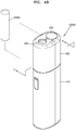
- FIG. 4A is a perspective view of an aerosol generating device according to an exemplary embodiment
- FIG. 4B is a perspective view showing an operating state of the aerosol generating device shown in FIG. 4A .
- the aerosol generating device 10000 includes a body portion 410 into which a cigarette 20000 may be inserted.
- a cover 420 is coupled to the upper portion of the body portion 410.
- the cover 420 is coupled to the body portion 410 in a detachable manner.
- a stopper 430 is installed on the upper surface of the cover 420 in a slidable manner.
- the structure of the aerosol generating device 10000 shown in FIGS. 4A and 4B is only one example, and is not limited thereto.
- the body portion 410 and the cover 420 may be an integral structure and not detachable from each other.
- the upper surface of the cover 420 is provided with a rail extending along the sliding movement direction of the stopper 430, and a first through hole 440 into which the cigarette 20000 is inserted.
- the rail may expose the inside of the cover 420.
- the present disclosure is not limited thereto, and the rail may have a closed structure such that the outside and the inside of the cover 420 are not connected.
- the upper surface of the cover 420 may include any suitable structure, instead of the rail, that allows the sliding movement of the stopper 430 .
- the stopper 430 may open and close the first through hole 440 by sliding along the upper end of the cover 420. For example, when the stopper 430 moves along the rail formed on the upper surface of the cover 420 to a position shown in FIG. 4B , the first through hole 440 is exposed to the outside so that at least a part of the cigarette 20000 may be inserted into the first through hole 440.
- a method of coupling the stopper 430 to the cover 420 is not limited to the configuration of the exemplary embodiment shown in FIGS. 4A and 4B .
- the stopper 430 may be coupled to the cover 420 by using a hinge coupling method such that the stopper 430 may open or close the cover 420.
- the body portion 410 may include a vaporizer 14000 for heating a liquid composition to generate aerosol as described with reference to FIGS. 1 and 2 , and may include one or more air flows for causing the generated aerosol to pass through the cigarette 20000 and discharged to the outside.
- the cover 420 may be coupled to the body portion 410 and may include a plurality of independent passages that guide air to an entrance of the vaporizer 14000 along at least a part of the surface of the body portion 410.
- the plurality of passages provided in the cover 420 will be described in detail with reference to FIG. 5 .
- FIG. 5 is a cross-sectional view taken along the line V-V of FIG. 4B to show a configuration of an aerosol generating device according to an exemplary embodiment.
- FIG. 5 an example of a state in which the cover 420 of the aerosol generating device 10000 is coupled to the body portion 410 is illustrated. Meanwhile, FIG. 5 only shows elements of the aerosol generating device 10000 related to the present embodiment. Accordingly, it will be understood by those skilled in the art that the general purpose elements other than the elements shown in FIG. 5 may be further included in the aerosol generating device 10000.
- the cover 420 may include an outer housing 510, a stopper 430, and an inner housing 520. At least one of the outer housing 510, the stopper 430, and the inner housing 520 may include a heat resistant material, and the heat resistant material may include a material capable of withstanding heat of 80°C or more. Being capable of withstanding heat of 80°C or more means that the melting point Tm of the heat resistant material is above 80 °C.
- the heat resistant material may be a heat resistant synthetic resin.
- the heat resistant material is the heat resistant synthetic resin
- at least one of the melting point and a glass transition temperature Tg of the heat resistant material may be 80 °C or more.
- the heat resistant material may include at least one of, for example, polypropylene, polyether ether ketone (PEEK), polyethylene, polypropylene, polyethylene terephthalate, polycyclohexylenedimethylene terephthalate, polyimide, sulfone resin, fluorine resin, and aramid.
- the sulfone resin may include a resin such as polyethylsulfone and polyphenylene sulfide
- the fluorine resin may include polytetrafluoroethylene (teflon).
- the heat resistant material may be any suitable material capable of withstanding heat of 40 °C or more, and the heat resistant material may be any suitable material capable of withstanding heat of 100 °C or more.
- the heat resistant material may be any suitable material capable of withstanding heat of 130 °C or more, for example, the heat resistant material may be any suitable material capable of withstanding heat of 200 °C or more, for example, the heat resistant material may be any suitable material capable of withstanding heat of 300 °C or more, and for example, the heat resistant material may be any suitable material capable of withstanding heat of 400 °C or more.
- the aerosol generating device 10000 may include a heat insulating portion on at least one of the inner and outer surfaces of the outer housing 510 and the inner housing 520.
- the heat insulating portion may include at least one heat insulating material.
- the heat insulating portion may include any suitable material that blocks the movement of heat through the heat insulating portion.
- the heat insulating portion may include at least one of a porous material, graphite, and ceramics, but is not limited thereto.
- the ceramic may be a porous ceramic.
- the outer housing 510 may refer to a case forming an appearance of the cover 420.
- the outer housing 510 may include the first through hole 440 arranged to correspond to a receiving hole 530 that is formed in the body portion 410 so that the cigarette 20000 is inserted.
- the first through hole 440 may be disposed coaxially with the receiving hole 530.
- the inner housing 520 may refer to a case forming the inner structure of the cover 420.
- the inner housing 520 may be spaced apart from the outer housing 510 to form a space so that the stopper 430 slides inside the outer housing 510. At least a part of the stopper 430 may be covered by the inner housing 520 when viewed from the bottom of the outer housing 510.
- the inner housing 520 may include a second through hole 540 that may be coaxially disposed with the first through hole 440.
- the second through hole 540 may be disposed to correspond to each other with the first through hole 440 and the receiving hole 530 and penetrated by the cigarette 20000.
- the cigarette 20000 may pass through the first through hole 440, the second through hole 540, and the receiving hole 530 sequentially.
- Each of the first through hole 440, the second through hole 540, and the receiving hole 530 may have a shape corresponding to the shape of the cigarette 20000.
- the shape of each of the first through hole 440, the second through hole 540, and the receiving hole 530 may be circular.
- the present disclosure is not limited thereto, and the shape of each of the first through hole 440, the second through hole 540, and the receiving hole 530 may be at least one of a circle, a semicircle, an ellipse, and a polygon.
- the diameter of the first through hole 440 may be greater than the diameter of the cigarette 20000 such that a gap through which air passes is formed between the cigarette 20000 and the first through hole 440 when the cigarette 20000 is inserted into the receiving hole 530.
- a first passage 545 may be formed between the inner housing 520 and the body portion 410 such that air flowing into the gap between the cigarette 20000 inserted into the receiving hole 530 and the first through hole 440 and passing through a second through hole 540 flows along the upper surface of the body portion 410.
- the diameter of the second through hole 540 may be greater than the diameter of the cigarette 20000 such that a gap through which air flows is formed between the cigarette 20000 and the second through hole 540 when the cigarette 20000 is inserted into the receiving hole 530.
- At least one of the outer housing 510 and the inner housing 520 may further include at least one support protrusion (not shown) to maintain an interval between the inner housing 520 and the body portion 410.
- a space may be formed between the inner housing 520 and the body portion 410 by the at least one support protrusion.
- the inner housing 520 may further include a third through hole 550 spaced apart from the second through hole 540.
- the second passage 555 may be formed between the outer housing 510 and the inner housing 520 in order to guide the air that flows into the gap between the cigarette 20000 inserted into the receiving hole 530 and the first through hole 440 to the side of the body portion 410.
- the air that flows into the gap between the cigarette 20000 and the first through hole 440 may flow along at least one of the first passage 545 extending to the entrance of the vaporizer 14000 through the second through hole 540 and the second passage 555 extending to the entrance of the vaporizer 14000 through the third through hole 550.
- the second passage 555 may be further added besides the first passage 545, and accordingly, the flow of air flowing into the vaporizer 14000 included in the aerosol generating device 10000 may be smooth.
- the width of the first passage 545 may be smaller than the width of the second passage 555, and accordingly, the influence of the flow change in the air caused by the addition of the second passage 555 may increase.
- the present disclosure is not limited thereto.
- an example of the inner housing 520 including the second through hole 540 and the third through hole 550 will be described in detail with reference to FIGS. 6A to 6D .
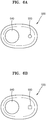
- FIGS. 6A to 6D are bottom views of examples of an inner housing included in a cover for an aerosol generating device according to an exemplary embodiment.
- the inner housing 520 further includes the third through hole 550 spaced apart from the circular second through hole 540 corresponding to the shape of the cigarette 20000.
- the third through hole 550 may have various shapes and sizes. For example, referring to FIG. 6A , the third through hole 550 having a circular cross section is shown, referring to FIG. 6B , the third through hole 550 having a rectangular cross section is shown, and referring to FIG. 6C , the third through hole 550 having an elliptical cross section is shown. Meanwhile, the cross-sectional shape of the third through hole 550 is not limited to the configuration of the embodiment in FIGS. 6A to 6C , and may be any suitable shape. For example, the shape of the third through hole 550 may be at least one of a circle, a semicircle, an ellipse, and a polygon.
- the third through hole 550 may include one or more holes.
- the third through hole 550 includes one hole in the exemplary embodiments shown in FIGS. 6A and 6B
- the third through hole 550 includes three holes in the exemplary embodiment shown in FIG. 6C .
- the number one or three is merely an example, and the third through hole 550 may include any suitable number of holes.
- the inner housing 520 may further include a filter member 610 disposed in the third through hole 550 in addition to the second through hole 540 and the third through hole 550.
- the filter member 610 allows air to pass through a plurality of holes, and may filter foreign substances, thereby preventing droplets formed when an aerosol generated by the vaporizer 14000 is liquefied again from leaking out through the third through hole 550.
- the filter member 610 may include a mesh material in which a plurality of holes are closely drilled like a mesh.
- Each of the plurality of holes included in the filter member 610 may have various sizes and various shapes.
- first group of holes included in the filter member 610 may have the same size that is different from the size of a second group of .
- the shape of each of the plurality of holes included in the filter member 610 may be at least one of a square, a rectangle, a parallelogram, and a rhombus.
- the filter member 610 may be a film or sheet shape structure such as a nonwoven fabric, and may include a polymer resin such as polyethylene, polypropylene, polyvinyl chloride resin, polyethylene terephthalate, nylon, epoxy, polyimide, polyester, urethane, acrylic, polycarbonate, urea, melanin, rubber chloride, polyvinyl alcohol, polyvinyl ester, vinylidene fluoride-hexafluoropropylene copolymer (PVDF-co-HFP), polyvinylidene fluoride (PVDF), polytetrafluoroethylene (PTFE), styrenebutadiene rubber (SBR), or ethylene-propylene-diene copolymer (EPDM).
- a polymer resin such as polyethylene, polypropylene, polyvinyl chloride resin, polyethylene terephthalate, nylon, epoxy, polyimide, polyester, urethane, acrylic, polycarbonate, urea, melanin,
- the outer housing 510 may further include an air inlet 560 formed at a part where the outer housing 510 and the body portion 410 are connected when the outer housing 510 is coupled to the body portion 410.
- the air inlet 560 may be formed along at least a part of the circumference of the outer housing 510.
- the air inlet 560 may be formed along the entire circumference of the outer housing 510, or may be formed only along a part of the circumference of the outer housing 510.
- examples of the air inlet 560 formed by the outer housing 510 will be described in detail with reference to FIGS. 7A to 7C .
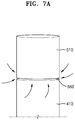
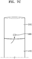
- FIGS. 7A to 7C are diagrams illustrating examples of an air inlet formed by a cover for an aerosol generating device according to an exemplary embodiment.
- the air inlet 560 may refer to a gap formed between the lower end of the outer housing 510 and the body portion 410 when the outer housing 510 and the body portion 410 are coupled. At this time, the air inlet 560 is formed along the entire circumference of the outer housing 510. Therefore, the outside air may flow into the aerosol generating device 10000 through the air inlet 560 along the entire circumference of the outer housing 510.
- the air inlet 560 may mean a gap formed by a groove provided in the lower end of the outer housing 510 at a portion where the outer housing 510 and the body portion 410 are connected when the outer housing 510 is coupled to the body portion 410. At this time, the air inlet 560 is formed along a part of the circumference of the outer housing 510.
- a rectangular groove is provided in the lower end of the outer housing 510, but is not limited thereto.
- a groove of any suitable shape may be provided in the lower end of the outer housing 510 to form the air inlet 560.
- the air inlet 560 may refer to a through hole formed spaced apart from the position where the outer housing 510 and the body portion 410 are connected to each other.
- the cross section of the air inlet 560 has a rectangular shape, but is not limited thereto.
- the air inlet 560 may be a through hole having any suitable cross sectional shape.
- the cross-sectional shape of the air inlet 560 may include at least one of a circle, a semicircle, an ellipse, and a polygon.
- FIGS. 7B and 7C Although only one air inlet 560 is shown in FIGS. 7B and 7C , it will be readily understood by those skilled in the art that a plurality of air inlets 560 may be formed spaced apart along the outer circumference of the outer housing 510. In addition, it will be readily understood by those skilled in the art that the air inlets 560 shown in FIGS. 7A to 7C may be combined and included in the aerosol generating device 10000.
- the cover 420 may further include a third passage 565 for guiding air that flows into through the air inlet 560 along at least a part of the surface of the body portion 410.
- air inhaled through the air inlet 560 may flow along the third passage 565 extending from the air inlet 560 to the vaporizer 14000.
- the cover 420 further includes the air inlet 560 in addition to the second through hole 540 and the third through hole 550, the third passage 565 may be added besides the first passage 545 and the second passage 555, and accordingly, the flow of air flowing into the entrance of the vaporizer 14000 included in the aerosol generating device 10000 may be smooth.
- End portions of a plurality of passages may be connected to each other at the entrance of the vaporizer 14000 such that air that flows into through each of the plurality of passages is induced to the entrance of the vaporizer 14000. Accordingly, air flowing through the first passage 545, air flowing through the second passage 555, and air flowing through the third passage 565 may all be combined at the entrance of the vaporizer 14000. The air combined at the entrance of the vaporizer 14000 may be delivered to a user through the cigarette 20000 along with the aerosol generated by the vaporizer 14000.
- the plurality of passages for inducing air to the entrance of the vaporizer 14000 included in the aerosol generating device 10000 are formed, and thus the air flow in the aerosol generating device 10000 may be smooth, and the performance degradation of the aerosol generating device 10000 may be effectively prevented.
- Table 1 below is a table showing a degree of ease of inhalation of the user according to the combination of the first passage 545, the second passage 555 and the third passage 565.
- Table 1 when 100 users perform a test of smoking cigarettes using an aerosol generating device 10000 including the combination of the first, second, and third passages 545, 555 and 565, ⁇ indicates that more than 85 users have determined that inhalation was easy, and ⁇ indicates that 50 to 80 users have determined that inhalation was easy, and X indicates that less than 50 users have determined that inhalation was easy.
- Combination of passageways Including only first passage Including first passage and second passage Including first passage and third passage Including all of first, second, and third passages Ease of Inhalation X ⁇ ⁇ ⁇
- Table 1 shows that at least two or more passages should be formed by the cover 420 of the aerosol generating device 10000 such that the air flow in the aerosol generating device 10000 may be smooth, and the performance degradation of the aerosol generating device 10000 may be effectively prevented.
Landscapes
- Engineering & Computer Science (AREA)
- Physics & Mathematics (AREA)
- Microelectronics & Electronic Packaging (AREA)
- Chemical & Material Sciences (AREA)
- General Chemical & Material Sciences (AREA)
- Chemical Kinetics & Catalysis (AREA)
- Health & Medical Sciences (AREA)
- General Physics & Mathematics (AREA)
- General Engineering & Computer Science (AREA)
- Optics & Photonics (AREA)
- Electromagnetism (AREA)
- General Health & Medical Sciences (AREA)
- Life Sciences & Earth Sciences (AREA)
- Computer Networks & Wireless Communication (AREA)
- Human Computer Interaction (AREA)
- Anesthesiology (AREA)
- Veterinary Medicine (AREA)
- Hematology (AREA)
- Biomedical Technology (AREA)
- Animal Behavior & Ethology (AREA)
- Pulmonology (AREA)
- Public Health (AREA)
- Heart & Thoracic Surgery (AREA)
- Bioinformatics & Cheminformatics (AREA)
- Agronomy & Crop Science (AREA)
- Botany (AREA)
- Toxicology (AREA)
- Disinfection, Sterilisation Or Deodorisation Of Air (AREA)
- Cigarettes, Filters, And Manufacturing Of Filters (AREA)
- Nozzles (AREA)
Abstract
Description
- The present disclosure relates to an aerosol generating device, and more particularly, to an aerosol generating device capable of generating an aerosol having various flavors by passing an aerosol generated by a vaporizer through a cigarette.
- Recently, the demand for alternative methods to overcome the shortcomings of general cigarettes has increased. For example, there is an increasing demand for a method of generating aerosol by heating an aerosol generating material in cigarettes, rather than by burning cigarettes. Accordingly, studies on a heating-type cigarette and a heating-type aerosol generating device have been actively conducted.
- Meanwhile, to provide a user with an improved smoking experience, an aerosol generating device that uses a liquid composition as an aerosol generating source with a cigarette has been developed. For example, there has been developed an aerosol generating device which includes a vaporizer for heating a liquid composition to generate an aerosol and allows the aerosol generated by the vaporizer to pass through the cigarette and be delivered to the user. However, in such an aerosol generating device air introduced into the aerosol generating device needs to pass through not only the cigarette but also the vaporizer to be delivered to the user. As a result, the air flow path may increase or may be more complex as compared to the related art. In this case, if the number of air inlets is maintained to be the same as in the related art, the performance of the aerosol generating device may be degraded because of unsmooth air flow in the aerosol generating device. Accordingly, technology for facilitating air flow in the aerosol generating device may be required.
- Provided are an aerosol generating device. The technical solution of the present disclosure is not limited to the above-described technical problems, and other technical problems may be deduced from the following embodiments. For example, an aerosol generating device may include a body portion comprising a vaporizer configured to heat a liquid composition to generate an aerosol and one or more air flow paths for causing the generated aerosol to pass through a cigarette and discharged to the outside, and a cover coupled to the body portion and comprising a plurality of passages comprising a first passage and a second passage which are independent from each other and guide air to an entrance of the vaporizer along at least a part of the surface of the body portion.
- The present disclosure may provide an aerosol generating device including a cover coupled to a body portion. Specifically, the aerosol generating device according to the present disclosure may include a body portion comprising a vaporizer for heating a liquid composition to generate an aerosol and one or more air flow paths for causing the generated aerosol to pass through a cigarette and discharged to the outside, and a cover coupled to the body portion and comprising a plurality of independent passages that guide air to an entrance of the vaporizer along at least a part of the surface of the body portion.
- According to the present disclosure, the plurality of passages through which air is introduced into the vaporizer included in the aerosol generating device are formed, thereby achieving a smooth air flow in the aerosol generating device, and effectively preventing the performance degradation of the aerosol generating device.
-
-
FIGS. 1 and 2 are diagrams showing examples in which a cigarette is inserted into an aerosol generating device. -
FIG. 3 is a drawing illustrating an example of a cigarette. -
FIG. 4A is a perspective view of an aerosol generating device according to an exemplary embodiment, andFIG. 4B is a perspective view showing an operating state of the aerosol generating device shown inFIG. 4A . -
FIG. 5 is a cross-sectional view taken along line V-V ofFIG. 4B to show a configuration of the aerosol generating device according to an exemplary embodiment. -
FIGS. 6A to 6D are bottom views of examples of an inner housing included in a cover for an aerosol generating device according to an exemplary embodiment. -
FIGS. 7A to 7C are diagrams illustrating examples of an air inlet formed by a cover for an aerosol generating device according to an exemplary embodiment. - According to an aspect of the present disclosure, an aerosol generating device may include a body portion comprising a vaporizer configured to generate aerosol by heating a liquid composition; and one or more air flow paths configured to cause the generated aerosol to pass through a cigarette and be discharged to outside; and a cover coupled to the body portion and comprising a plurality of passages comprising a first passage and a second passage which are independent from each other and guide air to an entrance of the vaporizer along at least part of a surface of the body portion.
- The cover may include an outer housing comprising a first through hole through which the cigarette penetrates and arranged to correspond to a receiving hole formed in the body portion into which the cigarette is inserted; a stopper configured to open or close the first through hole by sliding along an upper end of the outer housing; and an inner housing spaced apart from the outer housing to form a space such that the stopper slides inside the outer housing.
- The inner housing may include a second through hole disposed coaxially with the first through hole, and the first passage may be formed between the inner housing and the body portion such that air that flows into a gap between the cigarette inserted into the receiving hole and the first through hole and passing through the second through hole flows along an upper surface of the body portion.
- In an example, at least one of the outer housing and the inner housing may further include at least one support protrusion configured to maintain an interval between the inner housing and the body portion.
- Meanwhile, the inner housing may further include a third through hole spaced apart from the second through hole, and the second passage may be formed between the outer housing and the inner housing to guide the air that flows into the gap between the cigarette inserted into the receiving hole and the first through hole to a side of the body portion.
- A width of the first passage may be less than a width of the second passage.
- The inner housing may further include a filter member disposed on the third through hole and configured to pass through air and filter foreign substances.
- A cross-sectional shape of the third through hole may be at least one of a circle, a semicircle, an ellipse, and a polygon.
- The third through hole may include a plurality of holes.
- In an example the outer housing may further include an air inlet formed in a part where the outer housing and the body portion are connected when the outer housing is coupled to the body portion, and the cover may further include a third passage configured to guide air that flows into through the air inlet along at least a part of a surface of the body portion.
- The air inlet may be formed to extend along at least a part of a circumference of the outer housing.
- In another example, the outer housing may further include an air inlet formed to be spaced apart from a portion where the outer housing and the body portion are connected when the outer housing is coupled to the body portion, and the cover may further include a third passage configured to guide air that flows into through the air inlet along at least a part of a surface of the body portion.
- Meanwhile, end portions of the plurality of passages may be connected to each other at an entrance of the vaporizer such that air that flows into through each of the plurality of passages is induced to the entrance of the vaporizer.
- At least one of the outer housing and the inner housing may include a heat resistant material, and the heat resistant material may include a material capable of withstanding heat of 80 °C or more.
- With respect to the terms in the various embodiments, the general terms which are currently and widely used are selected in consideration of functions of structural elements in the various embodiments of the present disclosure. However, meanings of the terms can be changed according to intention, a judicial precedence, the appearance of a new technology, and the like. In addition, in certain cases, a term which is not commonly used can be selected. In such a case, the meaning of the term will be described in detail at the corresponding portion in the description of the present disclosure. Therefore, the terms used in the various embodiments of the present disclosure should be defined based on the meanings of the terms and the descriptions provided herein.
- In addition, unless explicitly described to the contrary, the word "comprise" and variations such as "comprises" or "comprising" will be understood to imply the inclusion of stated elements but not the exclusion of any other elements. In addition, the terms "-er", "-or", and "module" described in the specification mean units for processing at least one function and operation and can be implemented by hardware components or software components and combinations thereof.
- Hereinafter, the present disclosure will now be described more fully with reference to the accompanying drawings, in which exemplary embodiments of the present disclosure are shown such that one of ordinary skill in the art may easily work the present disclosure. The disclosure can, however, be embodied in many different forms and should not be construed as being limited to the embodiments set forth herein.
- Hereinafter, embodiments of the present disclosure will be described in detail with reference to the drawings.
-
FIGS. 1 and 2 are diagrams showing examples in which a cigarette is inserted into an aerosol generating device. - Referring to
FIGS. 1 and 2 , anaerosol generating device 10000 includes abattery 11000, acontroller 12000, aheater 13000, and avaporizer 14000. Also, acigarette 20000 may be inserted into an inner space of the aerosol generatingdevice 10000. -
FIGS. 1 and 2 only illustrate components of theaerosol generating device 10000, which are related to the present embodiment. Therefore, it will be understood by one of ordinary skill in the art that other general-purpose components may be further included in theaerosol generating device 10000, in addition to the components illustrated inFIG. 1 . - Also,
FIGS. 1 and 2 illustrate that theaerosol generating device 10000 includes theheater 13000. However, as necessary, theheater 13000 may be omitted. -
FIG. 1 illustrates that thebattery 11000, thecontroller 12000, thevaporizer 14000, and theheater 13000 are arranged in series. On the other hand,FIG. 2 illustrates that thevaporizer 14000 and theheater 13000 are arranged in parallel. However, the internal structure of theaerosol generating device 10000 is not limited to the structures illustrated inFIG. 1 or FIG. 2 . In other words, according to the design of theaerosol generating device 10000, thebattery 11000, thecontroller 12000, thevaporizer 14000, and theheater 13000 may be differently arranged. - When the
cigarette 20000 is inserted into theaerosol generating device 10000, theaerosol generating device 10000 may operate thevaporizer 14000 to generate aerosol. The aerosol generated by thevaporizer 14000 is delivered to the user by passing through thecigarette 20000. Thevaporizer 14000 will be described in more detail later. - The
battery 11000 may supply power to be used for theaerosol generating device 10000 to operate. For example, thebattery 11000 may supply power to heat theheater 13000 or thevaporizer 14000 and may supply power for operating thecontroller 12000. Also, thebattery 11000 may supply power for operations of a display, a sensor, a motor, etc. mounted in theaerosol generating device 10000. - The
controller 12000 may generally control operations of theaerosol generating device 10000. In detail, thecontroller 12000 may control not only operations of thebattery 11000, theheater 13000, and thevaporizer 14000, but also operations of other components included in theaerosol generating device 10000. Also, thecontroller 12000 may check a state of each of the components of theaerosol generating device 10000 to determine whether or not theaerosol generating device 10000 is in an operable state. - The
controller 12000 may include at least one processor. A processor can be implemented as an array of a plurality of logic gates or can be implemented as a combination of a general-purpose microprocessor and a memory in which a program executable in the microprocessor is stored. It will be understood by one of ordinary skill in the art that the processor can be implemented in other forms of hardware. - The
heater 13000 may be heated by the power supplied from thebattery 11000. For example, when thecigarette 20000 is inserted into theaerosol generating device 10000, theheater 13000 may be located outside thecigarette 20000 and increase a temperature of an aerosol generating material in thecigarette 20000. - The
heater 13000 may include an electro-resistive heater. For example, theheater 13000 may include an electrically conductive track, and theheater 13000 may be heated when currents flow through the electrically conductive track. However, theheater 13000 is not limited to the example described above and may include any other heaters which may be heated to a desired temperature. Here, the desired temperature may be pre-set in theaerosol generating device 10000 or may be set by a user. - As another example, the
heater 13000 may include an induction heater. In detail, theheater 13000 may include an electrically conductive coil for heating a cigarette in an induction heating method, and the cigarette may include a susceptor which may be heated by the induction heater. -
FIGS. 1 and 2 illustrate that theheater 13000 is positioned outside thecigarette 20000, but the position of theheater 13000 is not limited thereto. For example, theheater 13000 may include a tube-type heating element, a plate-type heating element, a needle-type heating element, or a rod-type heating element, and may heat the inside or the outside of thecigarette 20000, according to the shape of the heating element. - Also, the
aerosol generating device 10000 may include a plurality ofheaters 13000. Here, the plurality ofheaters 13000 may be inserted into thecigarette 20000 or may be arranged outside thecigarette 20000. Also, some of the plurality ofheaters 13000 may be inserted into thecigarette 20000, and the others may be arranged outside thecigarette 20000. In addition, the shape of theheater 13000 is not limited to the shapes illustrated inFIGS. 1 and 2 and may include various shapes. - The
vaporizer 14000 may generate aerosol by heating a liquid composition and the generated aerosol may pass through thecigarette 20000 to be delivered to a user. In other words, the aerosol generated by thevaporizer 14000 may move along an air flow passage of theaerosol generating device 10000. The air flow passage may be configured such that the aerosol generated by thevaporizer 14000 passes through thecigarette 20000 to be delivered to the user. - For example, the
vaporizer 14000 may include a liquid storage, a liquid delivery element, and a heating element, but it is not limited thereto. For example, the liquid storage, the liquid delivery element, and the heating element may be included in theaerosol generating device 10000 as independent modules. - The liquid storage may store a liquid composition. For example, the liquid composition may be a liquid including a tobacco-containing material having a volatile tobacco flavor component, or a liquid including a non-tobacco material. The liquid storage may be formed to be attachable/detachable to/from the
vaporizer 14000 or may be formed integrally with thevaporizer 14000. - For example, the liquid composition may include water, a solvent, ethanol, plant extract, spices, flavorings, or a vitamin mixture. The spices may include menthol, peppermint, spearmint oil, and various fruit-flavored ingredients, but are not limited thereto. The flavorings may include ingredients capable of providing various flavors or tastes to a user. Vitamin mixtures may be a mixture of at least one of vitamin A, vitamin B, vitamin C, and vitamin E, but are not limited thereto. Also, the liquid composition may include an aerosol forming substance, such as glycerin and propylene glycol.
- The liquid delivery element may deliver the liquid composition of the liquid storage to the heating element. For example, the liquid delivery element may be a wick such as cotton fiber, ceramic fiber, glass fiber, or porous ceramic, but is not limited thereto.
- The heating element is an element for heating the liquid composition delivered by the liquid delivery element. For example, the heating element may be a metal heating wire, a metal hot plate, a ceramic heater, or the like, but is not limited thereto. In addition, the heating element may include a conductive filament such as nichrome wire and may be wound around the liquid delivery element. The heating element may be heated by electrical current and may transfer heat to the liquid composition in contact with the heating element, thereby heating the liquid composition. As a result, aerosol may be generated.
- For example, the
vaporizer 14000 may be referred to as a cartomizer or an atomizer, but it is not limited thereto. - The
aerosol generating device 10000 may further include general-purpose components in addition to thebattery 11000, thecontroller 12000, and theheater 13000. For example, theaerosol generating device 10000 may include a display capable of outputting visual information and/or a motor for outputting haptic information. Also, theaerosol generating device 10000 may include at least one sensor (a puff detecting sensor, a temperature detecting sensor, a cigarette insertion detecting sensor, etc.). Also, theaerosol generating device 10000 may be formed as a structure where, even when thecigarette 20000 is inserted into theaerosol generating device 10000, external air may be introduced or internal air may be discharged. - Although not illustrated in
FIGS. 1 and 2 , a cradle may be used with theaerosol generating device 10000 to form a system. For example, the cradle may be used to charge thebattery 11000 of theaerosol generating device 10000. Alternatively, theheater 13000 may be heated when the cradle and theaerosol generating device 10000 are coupled to each other. - The
cigarette 20000 may be similar to a general combustive cigarette. For example, thecigarette 20000 may be divided into a first portion including an aerosol generating material and a second portion including a filter, etc. Alternatively, the second portion of thecigarette 20000 may also include an aerosol generating material. For example, an aerosol generating material made in the form of granules or capsules may be inserted into the second portion. The entire first portion may be inserted into theaerosol generating device 10000, and the second portion may be exposed to the outside. Alternatively, the first portion may be partially inserted into theaerosol generating device 10000. Otherwise, the first portion and a part of the second portion may be inserted into theaerosol generating device 10000. The user may puff aerosol while holding the second portion by the mouth of the user. In this case, the aerosol is generated by the external air passing through the first portion, and the generated aerosol passes through the second portion and is delivered to the user's mouth. - For example, the external air may flow into at least one air passage formed in the
aerosol generating device 10000. For example, opening and closing of the air passage and/or a size of the air passage may be adjusted by the user. Accordingly, the amount of smoke and a smoking impression may be adjusted by the user. As another example, the external air may flow into thecigarette 20000 through at least one hole formed in a surface of thecigarette 20000. - Hereinafter, an example of the
cigarette 20000 will be described with reference toFIG. 3. FIG. 3 is a drawing illustrating an example of a cigarette. - Referring to
FIG. 3 , thecigarette 20000 may include atobacco rod 21000 and afilter rod 22000. The first portion described above with reference toFIGS. 1 and 2 may include thetobacco rod 21000, and the second portion may include thefilter rod 22000. -
FIG. 3 illustrates that thefilter rod 22000 includes a single segment. However, thefilter rod 22000 is not limited thereto. In other words, thefilter rod 22000 may include a plurality of segments. For example, thefilter rod 22000 may include a first segment configured to cool aerosol and a second segment configured to filter a certain component included in the aerosol. Also, as necessary, thefilter rod 22000 may further include at least one segment configured to perform other functions. - The
cigarette 20000 may be packaged using at least onewrapper 24000. Thewrapper 24000 may have at least one hole through which external air may be introduced or internal air may be discharged. For example, thecigarette 20000 may be packaged using onewrapper 24000. As another example, thecigarette 20000 may be doubly packaged using at least twowrappers 24000. For example, thetobacco rod 21000 may be packaged using a first wrapper, and thefilter rod 22000 may be packaged using a second wrapper. Also, thetobacco rod 21000 and thefilter rod 22000, which are respectively packaged via separate wrappers, may be combined and packaged together using a third wrapper. When each of thetobacco rod 21000 and thefilter rod 22000 includes a plurality of segments, each segment may be packaged using a separate wrapper. Also, theentire cigarette 20000 including the plurality of segments, which are respectively packaged using the separate wrappers and coupled to each other, may be re-packaged using another wrapper. - The
tobacco rod 21000 may include an aerosol generating material. For example, the aerosol generating material may include at least one of glycerin, propylene glycol, ethylene glycol, dipropylene glycol, diethylene glycol, triethylene glycol, tetraethylene glycol, and oleyl alcohol, but it is not limited thereto. Also, thetobacco rod 21000 may include other additives, such as flavors, a wetting agent, and/or organic acid. Also, thetobacco rod 21000 may include a flavored liquid, such as menthol or a moisturizer, which is injected to thetobacco rod 21000. - The
tobacco rod 21000 may be manufactured in various forms. For example, thetobacco rod 21000 may be formed as a sheet or a strand. Also, thetobacco rod 21000 may be formed as a pipe tobacco, which is formed of tiny bits cut from a tobacco sheet. Also, thetobacco rod 21000 may be surrounded by a heat conductive material. For example, the heat conductive material may be, but is not limited to, a metal foil such as aluminum foil. For example, the heat conductive material surrounding thetobacco rod 21000 may uniformly distribute heat transmitted to thetobacco rod 21000, and thus, the heat conductivity applied to the tobacco rod may be increased and taste of the tobacco may be improved. - The
filter rod 22000 may include a cellulose acetate filter. Shapes of thefilter rod 22000 are not limited. For example, thefilter rod 22000 may include a cylinder-type rod or a tube-type rod having a hollow inside. Also, thefilter rod 22000 may include a recess-type rod. When thefilter rod 22000 includes a plurality of segments, at least one of the plurality of segments may have a different shape. - The
filter rod 22000 may be formed to generate flavors. For example, a flavoring liquid may be injected onto thefilter rod 22000, or an additional fiber coated with a flavoring liquid may be inserted into thefilter rod 22000. - Also, the
filter rod 22000 may include at least onecapsule 23000. Here, thecapsule 23000 may generate a flavor or aerosol. For example, thecapsule 23000 may have a structure in which a liquid containing a flavoring material is wrapped with a film. For example, thecapsule 23000 may have a spherical or cylindrical shape, but is not limited thereto. - When the
filter rod 22000 includes a segment configured to cool the aerosol, the cooling segment may include a polymer material or a biodegradable polymer material. For example, the cooling segment may include pure polylactic acid alone, but the material for forming the cooling segment is not limited thereto. In an exemplary embodiment, the cooling segment may include a cellulose acetate filter having a plurality of holes. However, the cooling segment is not limited to the above-described example and any other cooling segment that cools the aerosol may be used. - Although not illustrated in
FIG. 3 , thecigarette 20000 according to an exemplary embodiment may further include a front-end filter. The front-end filter may be located on a front side of thetobacco rod 21000, the side away from thefilter rod 22000. The front-end filter may prevent thetobacco rod 21000 from being detached and prevent liquefied aerosol from flowing into the aerosol generating device 10000 (FIGS. 1 and 2 ) from thetobacco rod 21000, during smoking. -
FIG. 4A is a perspective view of an aerosol generating device according to an exemplary embodiment, andFIG. 4B is a perspective view showing an operating state of the aerosol generating device shown inFIG. 4A . - Referring to
FIGS. 4A and4B , theaerosol generating device 10000 includes abody portion 410 into which acigarette 20000 may be inserted. Acover 420 is coupled to the upper portion of thebody portion 410. Thecover 420 is coupled to thebody portion 410 in a detachable manner. Astopper 430 is installed on the upper surface of thecover 420 in a slidable manner. However, the structure of theaerosol generating device 10000 shown inFIGS. 4A and4B is only one example, and is not limited thereto. For example, thebody portion 410 and thecover 420 may be an integral structure and not detachable from each other. - The upper surface of the
cover 420 is provided with a rail extending along the sliding movement direction of thestopper 430, and a first throughhole 440 into which thecigarette 20000 is inserted. The rail may expose the inside of thecover 420. However, the present disclosure is not limited thereto, and the rail may have a closed structure such that the outside and the inside of thecover 420 are not connected. In addition, the upper surface of thecover 420 may include any suitable structure, instead of the rail, that allows the sliding movement of thestopper 430 . - The
stopper 430 may open and close the first throughhole 440 by sliding along the upper end of thecover 420. For example, when thestopper 430 moves along the rail formed on the upper surface of thecover 420 to a position shown inFIG. 4B , the first throughhole 440 is exposed to the outside so that at least a part of thecigarette 20000 may be inserted into the first throughhole 440. - Meanwhile, a method of coupling the
stopper 430 to thecover 420 is not limited to the configuration of the exemplary embodiment shown inFIGS. 4A and4B . For example, thestopper 430 may be coupled to thecover 420 by using a hinge coupling method such that thestopper 430 may open or close thecover 420. - The
body portion 410 may include avaporizer 14000 for heating a liquid composition to generate aerosol as described with reference toFIGS. 1 and 2 , and may include one or more air flows for causing the generated aerosol to pass through thecigarette 20000 and discharged to the outside. - The
cover 420 may be coupled to thebody portion 410 and may include a plurality of independent passages that guide air to an entrance of thevaporizer 14000 along at least a part of the surface of thebody portion 410. Hereinafter, the plurality of passages provided in thecover 420 will be described in detail with reference toFIG. 5 . -
FIG. 5 is a cross-sectional view taken along the line V-V ofFIG. 4B to show a configuration of an aerosol generating device according to an exemplary embodiment. - Referring to
FIG. 5 , an example of a state in which thecover 420 of theaerosol generating device 10000 is coupled to thebody portion 410 is illustrated. Meanwhile,FIG. 5 only shows elements of theaerosol generating device 10000 related to the present embodiment. Accordingly, it will be understood by those skilled in the art that the general purpose elements other than the elements shown inFIG. 5 may be further included in theaerosol generating device 10000. - The
cover 420 may include anouter housing 510, astopper 430, and aninner housing 520. At least one of theouter housing 510, thestopper 430, and theinner housing 520 may include a heat resistant material, and the heat resistant material may include a material capable of withstanding heat of 80°C or more. Being capable of withstanding heat of 80°C or more means that the melting point Tm of the heat resistant material is above 80 °C. - Meanwhile, the heat resistant material may be a heat resistant synthetic resin. When the heat resistant material is the heat resistant synthetic resin, at least one of the melting point and a glass transition temperature Tg of the heat resistant material may be 80 °C or more.
- For example, the heat resistant material may include at least one of, for example, polypropylene, polyether ether ketone (PEEK), polyethylene, polypropylene, polyethylene terephthalate, polycyclohexylenedimethylene terephthalate, polyimide, sulfone resin, fluorine resin, and aramid. The sulfone resin may include a resin such as polyethylsulfone and polyphenylene sulfide, and the fluorine resin may include polytetrafluoroethylene (teflon). However, the present disclosure is not limited thereto, and for example, the heat resistant material may be any suitable material capable of withstanding heat of 40 °C or more, and the heat resistant material may be any suitable material capable of withstanding heat of 100 °C or more. Further, for example, the heat resistant material may be any suitable material capable of withstanding heat of 130 °C or more, for example, the heat resistant material may be any suitable material capable of withstanding heat of 200 °C or more, for example, the heat resistant material may be any suitable material capable of withstanding heat of 300 °C or more, and for example, the heat resistant material may be any suitable material capable of withstanding heat of 400 °C or more.
- In addition, the
aerosol generating device 10000 may include a heat insulating portion on at least one of the inner and outer surfaces of theouter housing 510 and theinner housing 520. The heat insulating portion may include at least one heat insulating material. For example, the heat insulating portion may include any suitable material that blocks the movement of heat through the heat insulating portion. For example, the heat insulating portion may include at least one of a porous material, graphite, and ceramics, but is not limited thereto. The ceramic may be a porous ceramic. - The
outer housing 510 may refer to a case forming an appearance of thecover 420. Theouter housing 510 may include the first throughhole 440 arranged to correspond to a receivinghole 530 that is formed in thebody portion 410 so that thecigarette 20000 is inserted. The first throughhole 440 may be disposed coaxially with the receivinghole 530. - The
inner housing 520 may refer to a case forming the inner structure of thecover 420. Theinner housing 520 may be spaced apart from theouter housing 510 to form a space so that thestopper 430 slides inside theouter housing 510. At least a part of thestopper 430 may be covered by theinner housing 520 when viewed from the bottom of theouter housing 510. - The
inner housing 520 may include a second throughhole 540 that may be coaxially disposed with the first throughhole 440. The second throughhole 540 may be disposed to correspond to each other with the first throughhole 440 and the receivinghole 530 and penetrated by thecigarette 20000. When thecigarette 20000 is inserted into theaerosol generating device 10000, thecigarette 20000 may pass through the first throughhole 440, the second throughhole 540, and the receivinghole 530 sequentially. - Each of the first through
hole 440, the second throughhole 540, and the receivinghole 530 may have a shape corresponding to the shape of thecigarette 20000. For example, when thecigarette 20000 is cylindrical, the shape of each of the first throughhole 440, the second throughhole 540, and the receivinghole 530 may be circular. However, the present disclosure is not limited thereto, and the shape of each of the first throughhole 440, the second throughhole 540, and the receivinghole 530 may be at least one of a circle, a semicircle, an ellipse, and a polygon. Meanwhile, the diameter of the first throughhole 440 may be greater than the diameter of thecigarette 20000 such that a gap through which air passes is formed between thecigarette 20000 and the first throughhole 440 when thecigarette 20000 is inserted into the receivinghole 530. - Among the plurality of passages that guide air to the entrance of the
vaporizer 14000 along at least a part of the surface of thebody portion 410, afirst passage 545 may be formed between theinner housing 520 and thebody portion 410 such that air flowing into the gap between thecigarette 20000 inserted into the receivinghole 530 and the first throughhole 440 and passing through a second throughhole 540 flows along the upper surface of thebody portion 410. Meanwhile, the diameter of the second throughhole 540 may be greater than the diameter of thecigarette 20000 such that a gap through which air flows is formed between thecigarette 20000 and the second throughhole 540 when thecigarette 20000 is inserted into the receivinghole 530. - In an example, at least one of the
outer housing 510 and theinner housing 520 may further include at least one support protrusion (not shown) to maintain an interval between theinner housing 520 and thebody portion 410. A space may be formed between theinner housing 520 and thebody portion 410 by the at least one support protrusion. - Meanwhile, the
inner housing 520 may further include a third throughhole 550 spaced apart from the second throughhole 540. Among the plurality of passages that guide the air to the entrance of thevaporizer 14000 along at least a part of the surface of thebody portion 410, thesecond passage 555 may be formed between theouter housing 510 and theinner housing 520 in order to guide the air that flows into the gap between thecigarette 20000 inserted into the receivinghole 530 and the first throughhole 440 to the side of thebody portion 410. - When the
cigarette 20000 is inserted into the receivinghole 530, the air that flows into the gap between thecigarette 20000 and the first throughhole 440 may flow along at least one of thefirst passage 545 extending to the entrance of thevaporizer 14000 through the second throughhole 540 and thesecond passage 555 extending to the entrance of thevaporizer 14000 through the third throughhole 550. - Because the
inner housing 520 of thecover 420 further includes the third throughhole 550 spaced apart from the second throughhole 540, thesecond passage 555 may be further added besides thefirst passage 545, and accordingly, the flow of air flowing into thevaporizer 14000 included in theaerosol generating device 10000 may be smooth. In an example, the width of thefirst passage 545 may be smaller than the width of thesecond passage 555, and accordingly, the influence of the flow change in the air caused by the addition of thesecond passage 555 may increase. However, the present disclosure is not limited thereto. Hereinafter, an example of theinner housing 520 including the second throughhole 540 and the third throughhole 550 will be described in detail with reference toFIGS. 6A to 6D . -
FIGS. 6A to 6D are bottom views of examples of an inner housing included in a cover for an aerosol generating device according to an exemplary embodiment. - Referring to
FIGS. 6A to 6D , theinner housing 520 further includes the third throughhole 550 spaced apart from the circular second throughhole 540 corresponding to the shape of thecigarette 20000. The third throughhole 550 may have various shapes and sizes. For example, referring toFIG. 6A , the third throughhole 550 having a circular cross section is shown, referring toFIG. 6B , the third throughhole 550 having a rectangular cross section is shown, and referring toFIG. 6C , the third throughhole 550 having an elliptical cross section is shown. Meanwhile, the cross-sectional shape of the third throughhole 550 is not limited to the configuration of the embodiment inFIGS. 6A to 6C , and may be any suitable shape. For example, the shape of the third throughhole 550 may be at least one of a circle, a semicircle, an ellipse, and a polygon. - Meanwhile, the third through
hole 550 may include one or more holes. For example, the third throughhole 550 includes one hole in the exemplary embodiments shown inFIGS. 6A and 6B , and the third throughhole 550 includes three holes in the exemplary embodiment shown inFIG. 6C . In the above embodiments, the number one or three is merely an example, and the third throughhole 550 may include any suitable number of holes. - Meanwhile, referring to
FIG. 6D , theinner housing 520 may further include afilter member 610 disposed in the third throughhole 550 in addition to the second throughhole 540 and the third throughhole 550. Thefilter member 610 allows air to pass through a plurality of holes, and may filter foreign substances, thereby preventing droplets formed when an aerosol generated by thevaporizer 14000 is liquefied again from leaking out through the third throughhole 550. - The
filter member 610 may include a mesh material in which a plurality of holes are closely drilled like a mesh. Each of the plurality of holes included in thefilter member 610 may have various sizes and various shapes. For example, first group of holes included in thefilter member 610 may have the same size that is different from the size of a second group of . In addition, the shape of each of the plurality of holes included in thefilter member 610 may be at least one of a square, a rectangle, a parallelogram, and a rhombus. - The
filter member 610 may be a film or sheet shape structure such as a nonwoven fabric, and may include a polymer resin such as polyethylene, polypropylene, polyvinyl chloride resin, polyethylene terephthalate, nylon, epoxy, polyimide, polyester, urethane, acrylic, polycarbonate, urea, melanin, rubber chloride, polyvinyl alcohol, polyvinyl ester, vinylidene fluoride-hexafluoropropylene copolymer (PVDF-co-HFP), polyvinylidene fluoride (PVDF), polytetrafluoroethylene (PTFE), styrenebutadiene rubber (SBR), or ethylene-propylene-diene copolymer (EPDM). - Referring back to
FIG. 5 , theouter housing 510 may further include anair inlet 560 formed at a part where theouter housing 510 and thebody portion 410 are connected when theouter housing 510 is coupled to thebody portion 410. Theair inlet 560 may be formed along at least a part of the circumference of theouter housing 510. For example, theair inlet 560 may be formed along the entire circumference of theouter housing 510, or may be formed only along a part of the circumference of theouter housing 510. Hereinafter, examples of theair inlet 560 formed by theouter housing 510 will be described in detail with reference toFIGS. 7A to 7C . -
FIGS. 7A to 7C are diagrams illustrating examples of an air inlet formed by a cover for an aerosol generating device according to an exemplary embodiment. - Referring to
FIG. 7A , theair inlet 560 may refer to a gap formed between the lower end of theouter housing 510 and thebody portion 410 when theouter housing 510 and thebody portion 410 are coupled. At this time, theair inlet 560 is formed along the entire circumference of theouter housing 510. Therefore, the outside air may flow into theaerosol generating device 10000 through theair inlet 560 along the entire circumference of theouter housing 510. - Referring to
FIG. 7B , theair inlet 560 may mean a gap formed by a groove provided in the lower end of theouter housing 510 at a portion where theouter housing 510 and thebody portion 410 are connected when theouter housing 510 is coupled to thebody portion 410. At this time, theair inlet 560 is formed along a part of the circumference of theouter housing 510. InFIG. 7B , a rectangular groove is provided in the lower end of theouter housing 510, but is not limited thereto. A groove of any suitable shape may be provided in the lower end of theouter housing 510 to form theair inlet 560. - Meanwhile, as shown in
FIG. 7C , theair inlet 560 may refer to a through hole formed spaced apart from the position where theouter housing 510 and thebody portion 410 are connected to each other. InFIG. 7C , the cross section of theair inlet 560 has a rectangular shape, but is not limited thereto. Theair inlet 560 may be a through hole having any suitable cross sectional shape. For example, the cross-sectional shape of theair inlet 560 may include at least one of a circle, a semicircle, an ellipse, and a polygon. - Meanwhile, although only one
air inlet 560 is shown inFIGS. 7B and7C , it will be readily understood by those skilled in the art that a plurality ofair inlets 560 may be formed spaced apart along the outer circumference of theouter housing 510. In addition, it will be readily understood by those skilled in the art that theair inlets 560 shown inFIGS. 7A to 7C may be combined and included in theaerosol generating device 10000. - Referring back to
FIG. 5 , thecover 420 may further include athird passage 565 for guiding air that flows into through theair inlet 560 along at least a part of the surface of thebody portion 410. For example, air inhaled through theair inlet 560 may flow along thethird passage 565 extending from theair inlet 560 to thevaporizer 14000. Because thecover 420 further includes theair inlet 560 in addition to the second throughhole 540 and the third throughhole 550, thethird passage 565 may be added besides thefirst passage 545 and thesecond passage 555, and accordingly, the flow of air flowing into the entrance of thevaporizer 14000 included in theaerosol generating device 10000 may be smooth. - End portions of a plurality of passages may be connected to each other at the entrance of the
vaporizer 14000 such that air that flows into through each of the plurality of passages is induced to the entrance of thevaporizer 14000. Accordingly, air flowing through thefirst passage 545, air flowing through thesecond passage 555, and air flowing through thethird passage 565 may all be combined at the entrance of thevaporizer 14000. The air combined at the entrance of thevaporizer 14000 may be delivered to a user through thecigarette 20000 along with the aerosol generated by thevaporizer 14000. - According to the structure of the
cover 420 for theaerosol generating device 10000 according to the present disclosure, the plurality of passages for inducing air to the entrance of thevaporizer 14000 included in theaerosol generating device 10000 are formed, and thus the air flow in theaerosol generating device 10000 may be smooth, and the performance degradation of theaerosol generating device 10000 may be effectively prevented. - For example, Table 1 below is a table showing a degree of ease of inhalation of the user according to the combination of the
first passage 545, thesecond passage 555 and thethird passage 565. In Table 1, when 100 users perform a test of smoking cigarettes using anaerosol generating device 10000 including the combination of the first, second, andthird passages [Table 1] Combination of passageways Including only first passage Including first passage and second passage Including first passage and third passage Including all of first, second, and third passages Ease of Inhalation X ○ ○ ⊚ - Table 1 shows that at least two or more passages should be formed by the
cover 420 of theaerosol generating device 10000 such that the air flow in theaerosol generating device 10000 may be smooth, and the performance degradation of theaerosol generating device 10000 may be effectively prevented. - It will be understood by one of ordinary skill in the art that various changes in form and details may be made therein without departing from the spirit and scope of the invention as defined by the appended claims. Therefore, the disclosed methods should be considered from an illustrative point of view, not from a restrictive point of view. The scope of the present disclosure is defined by the appended claims rather than by the foregoing description, and all differences within the scope of equivalents thereof should be construed as being included in the present disclosure.
Claims (15)
- An aerosol generating device comprising:a body portion comprising:a vaporizer configured to generate aerosol by heating a liquid composition; andone or more air flow paths configured to cause the generated aerosol to pass through a cigarette and be discharged to outside; anda cover coupled to the body portion and comprising a plurality of passages comprising a first passage and a second passage which are independent from each other and guide air to an entrance of the vaporizer along at least part of a surface of the body portion.
- The aerosol generating device of claim 1, wherein the cover comprises:an outer housing comprising a first through hole through which the cigarette penetrates and arranged to correspond to a receiving hole formed in the body portion into which the cigarette is inserted;a stopper configured to open or close the first through hole by sliding along an upper end of the outer housing; andan inner housing spaced apart from the outer housing to form a space such that the stopper slides inside the outer housing.
- The aerosol generating device of claim 2,
wherein the inner housing comprises a second through hole disposed coaxially with the first through hole, and
wherein the first passage is formed between the inner housing and the body portion such that air flowing into a gap between the cigarette inserted into the receiving hole and the first through hole and passing through the second through hole flows along an upper surface of the body portion. - The aerosol generating device of claim 3, wherein at least one of the outer housing and the inner housing further comprises at least one support protrusion configured to maintain an interval between the inner housing and the body portion.
- The aerosol generating device of claim 3, wherein the inner housing further includes a third through hole spaced apart from the second through hole, and
wherein the second passage is formed between the outer housing and the inner housing to guide the air that flows into the gap between the cigarette and the first through hole to a side of the body portion. - The aerosol generating device of claim 5, wherein a width of the first passage is less than a width of the second passage.
- The aerosol generating device of claim 5, wherein a cross-sectional shape of the third through hole is at least one of a circle, a semicircle, an ellipse, and a polygon.
- The aerosol generating device of claim 5, wherein the third through hole comprises a plurality of holes.
- The aerosol generating device of claim 5, wherein the inner housing further comprises a filter member disposed on the third through hole and configured to filter foreign substances from air passing through the filter member.
- The aerosol generating device of claim 2, wherein the outer housing further comprises an air inlet formed in a portion where the outer housing and the body portion are connected when the outer housing is coupled to the body portion, and
wherein the cover further comprises a third passage configured to guide air that flows in through the air inlet along at least part of a surface of the body portion. - The aerosol generating device of claim 10, wherein the air inlet extends along at least part of a circumference of the outer housing.
- The aerosol generating device of claim 2, wherein the outer housing further includes an air inlet formed to be spaced apart from a portion where the outer housing and the body portion are connected when the outer housing is coupled to the body portion, and
wherein the cover further comprises a third passage configured to guide air that flows in through the air inlet along at least part of a surface of the body portion. - The aerosol generating device of claim 1, wherein end portions of the plurality of passages are connected to each other at an entrance of the vaporizer such that air that flows in through each of the plurality of passages is directed to the entrance of the vaporizer.
- The aerosol generating device of claim 2, wherein at least one of the outer housing and the inner housing comprises a heat-resistant material.
- The aerosol generating device of claim 14, wherein the heat-resistant material comprises a material capable of withstanding heat of 80 °C or more.
Applications Claiming Priority (3)
| Application Number | Priority Date | Filing Date | Title |
|---|---|---|---|
| KR20170142578 | 2017-10-30 | ||
| KR1020180062137A KR102074935B1 (en) | 2017-10-30 | 2018-05-30 | An apparatus for generating aerosols |
| PCT/KR2018/012807 WO2019088586A2 (en) | 2017-10-30 | 2018-10-26 | Aerosol generating device |
Publications (2)
| Publication Number | Publication Date |
|---|---|
| EP3704965A2 true EP3704965A2 (en) | 2020-09-09 |
| EP3704965A4 EP3704965A4 (en) | 2021-09-08 |
Family
ID=66331449
Family Applications (1)
| Application Number | Title | Priority Date | Filing Date |
|---|---|---|---|
| EP18872527.9A Pending EP3704965A4 (en) | 2017-10-30 | 2018-10-26 | AEROSOL GENERATING DEVICE |
Country Status (5)
| Country | Link |
|---|---|
| US (2) | US12317923B2 (en) |
| EP (1) | EP3704965A4 (en) |
| JP (1) | JP6840291B2 (en) |
| CN (2) | CN110958841A (en) |
| WO (1) | WO2019088586A2 (en) |
Cited By (2)
| Publication number | Priority date | Publication date | Assignee | Title |
|---|---|---|---|---|
| EP4186379B1 (en) | 2019-07-01 | 2025-02-19 | Japan Tobacco Inc. | Container assembly and smoking system |
| US12550942B2 (en) | 2022-09-19 | 2026-02-17 | Altria Client Services Llc | Session control system |
Families Citing this family (25)
| Publication number | Priority date | Publication date | Assignee | Title |
|---|---|---|---|---|
| KR20180124739A (en) | 2017-05-11 | 2018-11-21 | 주식회사 케이티앤지 | An aerosol generating device for controlling the temperature of a heater according to the type of cigarette and method thereof |
| KR20190049391A (en) | 2017-10-30 | 2019-05-09 | 주식회사 케이티앤지 | Aerosol generating apparatus having heater |
| KR102138246B1 (en) | 2017-10-30 | 2020-07-28 | 주식회사 케이티앤지 | Vaporizer and aerosol generating apparatus comprising the same |
| KR102057215B1 (en) | 2017-10-30 | 2019-12-18 | 주식회사 케이티앤지 | Method and apparatus for generating aerosols |
| KR102180421B1 (en) | 2017-10-30 | 2020-11-18 | 주식회사 케이티앤지 | Apparatus for generating aerosols |
| EP3704963B1 (en) | 2017-10-30 | 2024-05-29 | KT&G Corporation | Optical module and aerosol generation device comprising same |
| KR102138245B1 (en) | 2017-10-30 | 2020-07-28 | 주식회사 케이티앤지 | Aerosol generating apparatus |
| PL3750418T3 (en) | 2017-10-30 | 2024-05-27 | Kt&G Corporation | Aerosol generating device and method for controlling same |
| JP6978580B2 (en) | 2017-10-30 | 2021-12-08 | ケイティー アンド ジー コーポレイション | Heaters for aerosol generators and aerosol generators |
| CN111050579B (en) | 2017-10-30 | 2023-03-17 | 韩国烟草人参公社 | Aerosol generating device |
| KR102057216B1 (en) | 2017-10-30 | 2019-12-18 | 주식회사 케이티앤지 | An apparatus for generating aerosols and A heater assembly therein |
| WO2019088586A2 (en) | 2017-10-30 | 2019-05-09 | 주식회사 케이티앤지 | Aerosol generating device |
| JP6884264B2 (en) | 2017-10-30 | 2021-06-09 | ケイティー アンド ジー コーポレイション | Aerosol generator |
| KR102203852B1 (en) * | 2018-11-16 | 2021-01-15 | 주식회사 케이티앤지 | Apparatus and system for generating aerosols |
| EP3979851A1 (en) * | 2019-06-05 | 2022-04-13 | Philip Morris Products S.A. | Aerosol-generating article comprising an aerosol-cooling element with peripheral openings |
| US12256787B2 (en) | 2019-10-17 | 2025-03-25 | Philip Morris Products S.A. | Charger and aerosol-generating system with rotatable cover |
| JP7650875B2 (en) | 2019-10-17 | 2025-03-25 | フィリップ・モーリス・プロダクツ・ソシエテ・アノニム | Charger and aerosol generating system having improved closure means |
| EP4044857B1 (en) | 2019-10-17 | 2023-11-29 | Philip Morris Products S.A. | Charger and aerosol-generating system with a multi-component cover |
| CN110664017B (en) * | 2019-11-05 | 2022-08-16 | 深圳市新宜康科技股份有限公司 | Method for alternately heating multiple heating bodies of atomizer and atomizer |
| CN111420620B (en) * | 2020-04-21 | 2025-06-17 | 深圳麦时科技有限公司 | Aerosol Generating Device |
| JP6890203B1 (en) | 2020-09-30 | 2021-06-18 | 日本たばこ産業株式会社 | Power supply unit of aerosol generator |
| JP6854961B1 (en) * | 2020-11-20 | 2021-04-07 | 日本たばこ産業株式会社 | Power supply unit for aerosol generator |
| WO2022123757A1 (en) * | 2020-12-11 | 2022-06-16 | 日本たばこ産業株式会社 | Fragrance inhaler |
| KR102533271B1 (en) * | 2021-03-16 | 2023-05-15 | 주식회사 케이티앤지 | Device for generating aerosol |
| JP1726573S (en) * | 2021-11-04 | 2022-10-05 | electronic cigarette |
Family Cites Families (294)
| Publication number | Priority date | Publication date | Assignee | Title |
|---|---|---|---|---|
| JPS537657Y2 (en) | 1971-11-20 | 1978-02-27 | ||
| US3886954A (en) * | 1974-03-13 | 1975-06-03 | Johannes Hermanus Hannema | Fire safety cigarette |
| JPS6215793A (en) | 1985-07-10 | 1987-01-24 | 三菱油化株式会社 | flexible heater |
| JPH0738943Y2 (en) | 1986-10-24 | 1995-09-06 | 三菱自動車工業株式会社 | Display device |
| US5093894A (en) | 1989-12-01 | 1992-03-03 | Philip Morris Incorporated | Electrically-powered linear heating element |
| US5408574A (en) | 1989-12-01 | 1995-04-18 | Philip Morris Incorporated | Flat ceramic heater having discrete heating zones |
| US5348027A (en) | 1991-02-14 | 1994-09-20 | R. J. Reynolds Tobacco Company | Cigarette with improved substrate |
| US5505214A (en) | 1991-03-11 | 1996-04-09 | Philip Morris Incorporated | Electrical smoking article and method for making same |
| US5665262A (en) | 1991-03-11 | 1997-09-09 | Philip Morris Incorporated | Tubular heater for use in an electrical smoking article |
| US5388594A (en) | 1991-03-11 | 1995-02-14 | Philip Morris Incorporated | Electrical smoking system for delivering flavors and method for making same |
| US5692525A (en) | 1992-09-11 | 1997-12-02 | Philip Morris Incorporated | Cigarette for electrical smoking system |
| JPH0673784U (en) | 1993-03-23 | 1994-10-18 | マルイ工業株式会社 | Display panel |
| JPH0772809A (en) | 1993-09-02 | 1995-03-17 | Toray Ind Inc | Microlens array sheet for liquid crystal display, and liquid crystal display using the same |
| US5555476A (en) | 1993-08-30 | 1996-09-10 | Toray Industries, Inc. | Microlens array sheet for a liquid crystal display, method for attaching the same and liquid crystal display equipped with the same |
| CR4906A (en) | 1993-09-10 | 1994-09-09 | Philip Morris Prod | ELECTRIC SMOKING SYSTEM TO DISTRIBUTE FLAVORS AND METHOD FOR ITS MANUFACTURE |
| JP3437287B2 (en) | 1994-10-21 | 2003-08-18 | 富士写真フイルム株式会社 | Film carrier |
| AR002035A1 (en) | 1995-04-20 | 1998-01-07 | Philip Morris Prod | A CIGARETTE, A CIGARETTE AND LIGHTER ADAPTED TO COOPERATE WITH THEMSELVES, A METHOD TO IMPROVE THE DELIVERY OF A SPRAY OF A CIGARETTE, A CONTINUOUS MATERIAL OF TOBACCO, A WORKING CIGARETTE, A MANUFACTURING MANUFACTURING METHOD , A METHOD FOR FORMING A HEATER AND AN ELECTRICAL SYSTEM FOR SMOKING |
| AU695608B2 (en) | 1995-06-07 | 1998-08-20 | Toyoda Gosei Co. Ltd. | Light-driven display device |
| JPH0975058A (en) | 1995-09-18 | 1997-03-25 | Masaya Nagai | Nicotine inhalator |
| CN1072472C (en) | 1995-10-21 | 2001-10-10 | 熊显耀 | Infrared health-care shoes |
| JP3553245B2 (en) | 1995-12-06 | 2004-08-11 | 本田技研工業株式会社 | Direct methanol fuel cell |
| DE69632550T2 (en) | 1995-12-06 | 2005-05-25 | Honda Giken Kogyo K.K. | Direct methanol fuel cell |
| JPH09228919A (en) | 1996-02-22 | 1997-09-02 | Keehin:Kk | Air-assisted electromagnetic fuel injection valve |
| JPH1037781A (en) | 1996-07-24 | 1998-02-10 | Suzuki Motor Corp | Mounting structure of intake pipe pressure sensor for internal combustion engine |
| US5934289A (en) | 1996-10-22 | 1999-08-10 | Philip Morris Incorporated | Electronic smoking system |
| US5878752A (en) * | 1996-11-25 | 1999-03-09 | Philip Morris Incorporated | Method and apparatus for using, cleaning, and maintaining electrical heat sources and lighters useful in smoking systems and other apparatuses |
| US5902501A (en) | 1997-10-20 | 1999-05-11 | Philip Morris Incorporated | Lighter actuation system |
| US5970719A (en) | 1998-03-02 | 1999-10-26 | Merritt; Thomas | Heating and cooling device |
| JP2001200495A (en) | 2000-01-14 | 2001-07-27 | Printing Bureau Ministry Of Finance | Coated paper for preventing forgery, its authenticity discrimination method and authenticity discrimination device |
| BR0109685B1 (en) | 2000-03-23 | 2013-07-23 | electric smoking system and method for cigarette smoking for electric smoking system | |
| KR200203233Y1 (en) | 2000-06-19 | 2000-11-15 | 최성문 | Portable cigarette case |
| US6615840B1 (en) | 2002-02-15 | 2003-09-09 | Philip Morris Incorporated | Electrical smoking system and method |
| US6803545B2 (en) | 2002-06-05 | 2004-10-12 | Philip Morris Incorporated | Electrically heated smoking system and methods for supplying electrical power from a lithium ion power source |
| US20050172976A1 (en) | 2002-10-31 | 2005-08-11 | Newman Deborah J. | Electrically heated cigarette including controlled-release flavoring |
| US6810883B2 (en) | 2002-11-08 | 2004-11-02 | Philip Morris Usa Inc. | Electrically heated cigarette smoking system with internal manifolding for puff detection |
| JP3898118B2 (en) | 2002-12-05 | 2007-03-28 | シンワ測定株式会社 | Manufacturing method of sheet heating device having temperature detection function |
| JP3975440B2 (en) | 2002-12-27 | 2007-09-12 | 株式会社山武 | Flow meter and smoking device |
| US7082825B2 (en) | 2002-12-27 | 2006-08-01 | Yamatake Corporation | Smoking device including a flowmeter |
| US6803550B2 (en) | 2003-01-30 | 2004-10-12 | Philip Morris Usa Inc. | Inductive cleaning system for removing condensates from electronic smoking systems |
| KR100750586B1 (en) | 2003-12-26 | 2007-08-20 | 한국전자통신연구원 | Microfluidic heating system |
| CA2552895A1 (en) | 2004-01-16 | 2005-07-28 | Mitsubishi Cable Industries Ltd. | Handle grip with heater |
| JP4447929B2 (en) | 2004-01-16 | 2010-04-07 | 三菱電線工業株式会社 | Heating element for handle grip |
| CN2719043Y (en) | 2004-04-14 | 2005-08-24 | 韩力 | Atomized electronic cigarette |
| JP2006252897A (en) | 2005-03-10 | 2006-09-21 | Harison Toshiba Lighting Corp | Heater, heating device, image forming apparatus |
| JP2006292620A (en) | 2005-04-13 | 2006-10-26 | Shibaura Electronics Co Ltd | Indirectly heated thermistor |
| US20060267614A1 (en) | 2005-05-24 | 2006-11-30 | Youn-Seob Lee | Ceramic heater |
| KR100782063B1 (en) | 2005-05-24 | 2007-12-04 | 주식회사 스마텍 | Ceramic Heater |
| KR100560332B1 (en) | 2005-06-01 | 2006-03-14 | 삼성광주전자 주식회사 | Dust collecting / fixing device and cyclone dust collecting device having the same |
| JP2007101639A (en) | 2005-09-30 | 2007-04-19 | Dainippon Printing Co Ltd | Filter for image display device and manufacturing method thereof |
| US20070102013A1 (en) | 2005-09-30 | 2007-05-10 | Philip Morris Usa Inc. | Electrical smoking system |
| US20070074734A1 (en) | 2005-09-30 | 2007-04-05 | Philip Morris Usa Inc. | Smokeless cigarette system |
| CN100581398C (en) | 2006-02-27 | 2010-01-20 | 何文天 | Environmentally friendly cigarette case that can eject cigarettes automatically |
| US7726320B2 (en) * | 2006-10-18 | 2010-06-01 | R. J. Reynolds Tobacco Company | Tobacco-containing smoking article |
| CA2683884C (en) | 2007-04-18 | 2012-10-30 | Japan Tobacco Inc. | Smoking article |
| CN101301963B (en) | 2007-05-08 | 2016-09-14 | 北京银融科技有限责任公司 | The management method of a kind of pipeline transmission and device |
| WO2009044716A1 (en) | 2007-10-01 | 2009-04-09 | Koha Co., Ltd. | Light emitting device |
| US9110249B2 (en) | 2007-10-02 | 2015-08-18 | Telescent Inc. | In-line fiber optic monitors responsive to optical intensity |
| CN101324490B (en) * | 2008-07-25 | 2010-08-04 | 北京汇丰隆生物科技发展有限公司 | A large-flow aerosol sampling device |
| CN201253138Y (en) | 2008-08-05 | 2009-06-10 | 宋建新 | Safe environmental protection type instant-hot type drinking device |
| CN201314692Y (en) | 2008-08-19 | 2009-09-23 | 刘雷刚 | Electromagnetic rapid water boiler |
| TW201023769A (en) | 2008-10-23 | 2010-07-01 | Japan Tobacco Inc | Non-burning type flavor inhalation article |
| AT507187B1 (en) | 2008-10-23 | 2010-03-15 | Helmut Dr Buchberger | INHALER |
| EP2201850A1 (en) | 2008-12-24 | 2010-06-30 | Philip Morris Products S.A. | An article including identification information for use in an electrically heated smoking system |
| CN101518361B (en) | 2009-03-24 | 2010-10-06 | 北京格林世界科技发展有限公司 | High-simulation electronic cigarette |
| JP2010266425A (en) | 2009-04-15 | 2010-11-25 | Toyota Motor Corp | Hydrogen pressure sensor |
| EP2253233A1 (en) | 2009-05-21 | 2010-11-24 | Philip Morris Products S.A. | An electrically heated smoking system |
| RU2529387C2 (en) | 2009-08-07 | 2014-09-27 | Кайнд Консьюмер Лимитед | Inhaler |
| KR200460461Y1 (en) | 2009-09-30 | 2012-05-25 | 주식회사 손엔 | Charging apparatus for vaporizing and inhaling apparatus |
| EP2319334A1 (en) | 2009-10-27 | 2011-05-11 | Philip Morris Products S.A. | A smoking system having a liquid storage portion |
| EP2316286A1 (en) | 2009-10-29 | 2011-05-04 | Philip Morris Products S.A. | An electrically heated smoking system with improved heater |
| EP2327318A1 (en) | 2009-11-27 | 2011-06-01 | Philip Morris Products S.A. | An electrically heated smoking system with internal or external heater |
| EP2340729A1 (en) | 2009-12-30 | 2011-07-06 | Philip Morris Products S.A. | An improved heater for an electrically heated aerosol generating system |
| EP2340730A1 (en) | 2009-12-30 | 2011-07-06 | Philip Morris Products S.A. | A shaped heater for an aerosol generating system |
| KR20110008931U (en) | 2010-03-12 | 2011-09-20 | 주식회사 손엔 | Vaporization suction device |
| CN201657047U (en) | 2010-03-23 | 2010-11-24 | 国基电子(上海)有限公司 | mobile phone |
| CN102970885B (en) | 2010-04-30 | 2015-05-20 | 洛艾克有限公司 | Electronic smoking device |
| GB201009042D0 (en) | 2010-06-01 | 2010-07-14 | Dunlop Oil & Marine Ltd | Leak detector |
| KR101012472B1 (en) | 2010-07-15 | 2011-02-08 | 양재성 | Condensing signs |
| KR101239080B1 (en) | 2010-09-01 | 2013-03-06 | (주)제로스인터내셔널 | Handy Nebulizer with Negative Ion Generator |
| KR20120050568A (en) | 2010-11-11 | 2012-05-21 | (주)데캉코리아 | Multi-function electronic cigarette |
| EP2460424A1 (en) | 2010-12-03 | 2012-06-06 | Philip Morris Products S.A. | An aerosol generating system with leakage prevention |
| EP2460422A1 (en) | 2010-12-03 | 2012-06-06 | Philip Morris Products S.A. | An aerosol generating system with provention of condensate leakage |
| EP2460423A1 (en) | 2010-12-03 | 2012-06-06 | Philip Morris Products S.A. | An electrically heated aerosol generating system having improved heater control |
| KR101057774B1 (en) | 2010-12-13 | 2011-08-19 | 신종수 | Electronic cigarette |
| EP2469969A1 (en) | 2010-12-24 | 2012-06-27 | Philip Morris Products S.A. | Reduced ceramic heating element |
| CN201996322U (en) | 2011-03-09 | 2011-10-05 | 潘毅强 | Full-automatic brewing machine |
| KR20120007263U (en) | 2011-04-13 | 2012-10-23 | (주)데캉코리아 | electronic-cigarette with cartridge |
| US9347644B2 (en) | 2011-04-22 | 2016-05-24 | Sharp Kabushiki Kaisha | Lens and light source unit |
| KR20120008751U (en) | 2011-06-13 | 2012-12-24 | 이영찬 | an electronic cigarette |
| KR101062248B1 (en) * | 2011-06-20 | 2011-09-05 | 신종수 | Electronic cigarette |
| US8528569B1 (en) | 2011-06-28 | 2013-09-10 | Kyle D. Newton | Electronic cigarette with liquid reservoir |
| WO2013007020A1 (en) | 2011-07-12 | 2013-01-17 | Liu Qiuming | Electronic flue-cured tobacco |
| CN103732280B (en) | 2011-08-19 | 2016-01-06 | 日本烟草产业株式会社 | Aerosol Aspirator |
| KR101289032B1 (en) | 2011-09-20 | 2013-07-23 | 서울과학기술대학교 산학협력단 | Auto-lighting Having Cigarette Case |
| AT511344B1 (en) | 2011-10-21 | 2012-11-15 | Helmut Dr Buchberger | INHALATORKOMPONENTE |
| PT2770859T (en) | 2011-10-27 | 2019-03-21 | Philip Morris Products Sa | Aerosol generating system with improved aerosol production |
| CN202385727U (en) | 2011-11-03 | 2012-08-22 | 湖北中烟工业有限责任公司 | Flammable harmless atomizer cigarette |
| CN103997922B (en) | 2011-11-21 | 2016-12-14 | 菲利普莫里斯生产公司 | Extractors for aerosol generating devices |
| TW201330884A (en) | 2011-12-07 | 2013-08-01 | Philip Morris Prod | An aerosol generating device having airflow inlets |
| KR102166921B1 (en) | 2011-12-08 | 2020-10-19 | 필립모리스 프로덕츠 에스.에이. | An aerosol generating device with adjustable airflow |
| KR101338073B1 (en) | 2011-12-09 | 2013-12-06 | 기아자동차주식회사 | Apparatus for indicating multi-symbol |
| JP2015500647A (en) | 2011-12-18 | 2015-01-08 | エスアイエス・リソーシズ・リミテッド | Rechargeable electronic cigarette |
| MX357545B (en) | 2011-12-30 | 2018-07-13 | Philip Morris Products Sa | AEROSOL GENERATOR SYSTEM WITH CONSUMPTION AND FEEDBACK MONITORING. |
| UA114306C2 (en) | 2011-12-30 | 2017-05-25 | Філіп Морріс Продактс С.А. | Aerosol generating device with air flow detection |
| PL2797445T3 (en) | 2011-12-30 | 2016-11-30 | Aerosol generating device with improved temperature distribution | |
| EP2609821A1 (en) | 2011-12-30 | 2013-07-03 | Philip Morris Products S.A. | Method and apparatus for cleaning a heating element of aerosol-generating device |
| PL3092909T3 (en) | 2012-01-03 | 2021-09-20 | Philip Morris Products S.A. | POWER SUPPLY SYSTEM FOR PORTABLE AEROSOL DEVICE |
| TWI584745B (en) | 2012-01-03 | 2017-06-01 | 菲利浦莫里斯製品股份有限公司 | Non-rolling aerosol-generating device and system |
| BR112014016266B1 (en) | 2012-01-03 | 2020-11-10 | Philip Morris Products S.A. | electrical system |
| AU2012364360B2 (en) | 2012-01-03 | 2016-11-24 | Philip Morris Products S.A. | An aerosol generating device and system with improved airflow |
| KR20130084789A (en) | 2012-01-18 | 2013-07-26 | 이영인 | Electronic cigarette |
| US9854839B2 (en) | 2012-01-31 | 2018-01-02 | Altria Client Services Llc | Electronic vaping device and method |
| US20130255675A1 (en) | 2012-04-01 | 2013-10-03 | Huizhou Kimree Technology Co., Ltd. | Electronic Cigarette and Mouthpiece Part Thereof |
| DE102012210037A1 (en) | 2012-06-14 | 2013-12-19 | Hauni Maschinenbau Ag | Measuring device and method for optical inspection of an end face of a cross-axially conveyed rod-shaped product of the tobacco processing industry |
| CN202854031U (en) | 2012-08-08 | 2013-04-03 | 谢洪 | Glue detection device for strip box paper on cigarette strip box packaging machine |
| US8881737B2 (en) | 2012-09-04 | 2014-11-11 | R.J. Reynolds Tobacco Company | Electronic smoking article comprising one or more microheaters |
| ES2613050T3 (en) | 2012-09-10 | 2017-05-22 | Ght Global Heating Technologies Ag | Liquid vaporization device for inhalation |
| KR101619034B1 (en) | 2012-09-11 | 2016-05-18 | 필립모리스 프로덕츠 에스.에이. | Device and method for controlling an electrical heater to control temperature |
| GB201216621D0 (en) | 2012-09-18 | 2012-10-31 | British American Tobacco Co | Heading smokeable material |
| CN202907797U (en) | 2012-09-29 | 2013-05-01 | 吴昌明 | Electronic smoking device |
| KR101426352B1 (en) | 2012-10-04 | 2014-08-05 | 주식회사 시그닛코리아 | Electronic cigarette |
| JP5992388B2 (en) | 2012-12-03 | 2016-09-14 | 日本碍子株式会社 | Ceramic heater |
| KR101465846B1 (en) | 2012-12-27 | 2014-11-26 | 주식회사 케이티앤지 | Cartridge and apparatus to inhale aerosol having the same |
| UA114651C2 (en) | 2012-12-28 | 2017-07-10 | Філіп Морріс Продактс С.А. | Heating assembly for an aerosol generating system |
| US8910640B2 (en) | 2013-01-30 | 2014-12-16 | R.J. Reynolds Tobacco Company | Wick suitable for use in an electronic smoking article |
| CN203040065U (en) | 2013-02-01 | 2013-07-03 | 青岛海信电子技术服务有限公司工业设计中心 | Electronic device provided with novel snap joint locking device |
| US9375034B2 (en) | 2013-02-05 | 2016-06-28 | Atmos Nation Llc | Combination electric lighter and portable vaporization device |
| CN103099319B (en) * | 2013-02-05 | 2015-07-08 | 广东精进能源有限公司 | Electronic cigarette |
| US20140261487A1 (en) | 2013-03-14 | 2014-09-18 | R. J. Reynolds Tobacco Company | Electronic smoking article with improved storage and transport of aerosol precursor compositions |
| US10098381B2 (en) * | 2013-03-15 | 2018-10-16 | Altria Client Services Llc | Electronic smoking article |
| JP2014216287A (en) | 2013-04-30 | 2014-11-17 | 清水 和彦 | Heater for smokeless smoking jig |
| KR102048924B1 (en) | 2013-05-16 | 2019-11-27 | 삼성디스플레이 주식회사 | Organic light emitting display apparatus |
| CN103271447A (en) | 2013-05-23 | 2013-09-04 | 红云红河烟草(集团)有限责任公司 | Novel carbon heating electron cigarette |
| GB2514893B (en) | 2013-06-04 | 2017-12-06 | Nicoventures Holdings Ltd | Container |
| US9541820B2 (en) | 2013-08-29 | 2017-01-10 | Casio Computer Co., Ltd. | Light source unit including an area of luminescent material emitting luminescent light in green wavelength range on part of member situated on optical path of light in blue wavelength range and projector |
| GB2518598B (en) | 2013-08-30 | 2016-06-01 | Nicoventures Holdings Ltd | Apparatus with battery power control |
| CA2852318A1 (en) | 2013-09-16 | 2015-03-16 | Cameron Lanning Cormack | Printed battery for electronic personal vaporizer |
| ES2762171T3 (en) | 2013-09-30 | 2020-05-22 | Japan Tobacco Inc | Non-Combustion Type Aroma Inhaler |
| CN203492793U (en) | 2013-10-17 | 2014-03-26 | 向智勇 | Electronic cigarette |
| KR101480423B1 (en) | 2013-10-22 | 2015-01-13 | 주식회사 프로모파트너스 | an advertising Panel using in LED |
| CN103519351B (en) | 2013-10-31 | 2017-02-15 | 红塔烟草(集团)有限责任公司 | Electrical heating cigarette |
| US9402422B2 (en) * | 2013-11-01 | 2016-08-02 | Yuval Shenkal | Hybrid e-cigarette/vaporizer with exhale filter capability |
| CN105722412B (en) | 2013-11-13 | 2019-04-12 | 吉瑞高新科技股份有限公司 | Atomizing device, electronic cigarette and method for adjusting e-liquid thereof |
| CN103653258A (en) | 2013-11-27 | 2014-03-26 | 浙江中烟工业有限责任公司 | Sectional heating device for non-combustion cigarettes |
| CN103653257B (en) | 2013-11-27 | 2015-12-09 | 浙江中烟工业有限责任公司 | A segmented heat-not-burn smoking device |
| HUE071643T2 (en) | 2013-12-03 | 2025-09-28 | Philip Morris Products Sa | Aerosol-generating article and electrically operated system incorporating a taggant |
| EA038916B1 (en) | 2013-12-05 | 2021-11-09 | Филип Моррис Продактс С.А. | Aerosol-generating article with low resistance air flow path |
| CN103720056A (en) | 2013-12-13 | 2014-04-16 | 浙江中烟工业有限责任公司 | Resistance wire heating device for non-burning cigarettes |
| KR102650793B1 (en) | 2014-02-10 | 2024-03-26 | 필립모리스 프로덕츠 에스.에이. | An aerosol-generating system having a fluid-permeable heater assembly |
| CN203723449U (en) | 2014-02-12 | 2014-07-23 | 刘秋明 | Electronic cigarette |
| DE202014001718U1 (en) | 2014-02-27 | 2015-05-28 | Xeo Holding GmbH | smoking device |
| US9839238B2 (en) | 2014-02-28 | 2017-12-12 | Rai Strategic Holdings, Inc. | Control body for an electronic smoking article |
| MY179623A (en) | 2014-03-21 | 2020-11-11 | Nicoventures Trading Ltd | Apparatus for heating smokable material and article of smokable material |
| KR20150111021A (en) | 2014-03-24 | 2015-10-05 | 삼성디스플레이 주식회사 | Light source module, backlight assembly including the same, and display device including the light source module |
| GB2524736B (en) | 2014-03-31 | 2021-02-24 | Nicoventures Holdings Ltd | Re-charging pack for an e-cigarette |
| SG11201605638PA (en) | 2014-03-31 | 2016-08-30 | Philip Morris Products Sa | Electrically heated aerosol-generating system |
| CN103859609B (en) | 2014-04-03 | 2016-05-11 | 惠州市吉瑞科技有限公司 | Electronic cigarette and electronic cigarette atomizing control method |
| US9877510B2 (en) | 2014-04-04 | 2018-01-30 | Rai Strategic Holdings, Inc. | Sensor for an aerosol delivery device |
| WO2015165747A1 (en) | 2014-04-30 | 2015-11-05 | Philip Morris Products S.A. | Aerosol generating device with battery indication |
| WO2015168828A1 (en) | 2014-05-04 | 2015-11-12 | 吉瑞高新科技股份有限公司 | Electronic cigarette and atomization control method therefor |
| KR101631286B1 (en) | 2014-05-12 | 2016-06-16 | 신종수 | Electronic cigarette |
| PL3142506T3 (en) | 2014-05-13 | 2019-07-31 | Fontem Holdings 4 B.V. | Electronic smoking device and data exchange applications |
| TWI666992B (en) | 2014-05-21 | 2019-08-01 | 瑞士商菲利浦莫里斯製品股份有限公司 | Aerosol-generating system and cartridge for usein the aerosol-generating system |
| DE102014108356A1 (en) | 2014-06-13 | 2015-12-17 | Innovative Sensor Technology Ist Ag | Planar heating element with a PTC resistor structure |
| EP3166425B1 (en) | 2014-07-11 | 2018-06-13 | Philip Morris Products S.a.s. | Aerosol-generating system comprising a removable heater |
| KR102534659B1 (en) | 2014-07-11 | 2023-05-19 | 필립모리스 프로덕츠 에스.에이. | Aerosol-generating system with improved air flow control |
| CN204120226U (en) | 2014-07-15 | 2015-01-28 | 刘水根 | Electronic Tobacco Vaporizer |
| GB201412600D0 (en) | 2014-07-16 | 2014-08-27 | Strutt Benjamin J And Bititsios Stergios And Cane Michael R | Inhalation device with a touch or proximity sensitive user interface which controls the device functionality when specific gestures are performed by the user |
| RS58459B1 (en) | 2014-07-24 | 2019-04-30 | Nicoventures Holdings Ltd | Re-charging pack for an e-cigarette |
| GB2559281B (en) | 2014-07-29 | 2019-05-15 | Nicoventures Holdings Ltd | E-cigarette and re-charging pack |
| CN104146353B (en) * | 2014-07-30 | 2015-10-07 | 普维思信(北京)科技有限公司 | A kind of low-temperature heat type electronic cigarette heater |
| CN104188110A (en) | 2014-08-05 | 2014-12-10 | 深圳市合元科技有限公司 | Curing-type electronic cigarette |
| CN116172269A (en) | 2014-08-13 | 2023-05-30 | 菲利普莫里斯生产公司 | Aerosol generating system including a multipurpose computing device |
| WO2016029471A1 (en) | 2014-08-29 | 2016-03-03 | 深圳麦克韦尔股份有限公司 | Electronic cigarette and atomizing component mounting base thereof |
| KR101736445B1 (en) | 2014-09-15 | 2017-05-31 | 주식회사 제이에프티 | Electronic cigarette |
| KR102185235B1 (en) | 2014-10-10 | 2020-12-02 | 삼성디스플레이 주식회사 | Display device |
| GB201418817D0 (en) | 2014-10-22 | 2014-12-03 | British American Tobacco Co | Apparatus and method for generating an inhalable medium, and a cartridge for use therewith |
| CN204146340U (en) | 2014-10-24 | 2015-02-11 | 深圳市杰仕博科技有限公司 | The easy electronic atomization device changing atomization core |
| CN204132401U (en) | 2014-10-24 | 2015-02-04 | 深圳市云享科技有限公司 | Atomizer and electronic cigarette |
| US10842195B2 (en) | 2014-10-29 | 2020-11-24 | Jt International S.A. | Aerosol generating device |
| CN204317492U (en) | 2014-11-14 | 2015-05-13 | 深圳市合元科技有限公司 | Be applicable to atomising device and the electronic cigarette of fluid matrix |
| KR101486294B1 (en) | 2014-11-14 | 2015-01-27 | 전병철 | A electronic cigarette |
| CN204317502U (en) | 2014-12-01 | 2015-05-13 | 深圳佳品健怡科技有限公司 | Electronic cigarette |
| GB2533137A (en) | 2014-12-11 | 2016-06-15 | Nicoventures Holdings Ltd | Electronic vapour provision system |
| GB2533135B (en) * | 2014-12-11 | 2020-11-11 | Nicoventures Holdings Ltd | Aerosol provision systems |
| EP3229622B1 (en) | 2014-12-11 | 2019-10-16 | Philip Morris Products S.a.s. | Inhaling device with user recognition based on inhalation behaviour |
| TWI674071B (en) * | 2014-12-15 | 2019-10-11 | 瑞士商菲利浦莫里斯製品股份有限公司 | Aerosol-generating systems and methods for guiding an airflow inside an electrically heated aerosol-generating system |
| MX2017007760A (en) | 2014-12-15 | 2017-09-05 | Philip Morris Products Sa | An aerosol-generating system using the venturi effect to deliver substrate to a heating element. |
| AR103016A1 (en) * | 2014-12-15 | 2017-04-12 | Philip Morris Products Sa | AEROSOL GENERATOR SYSTEMS AND METHODS FOR DIRECTING AN AIR FLOW TOWARDS AN ELECTRIC HEATED AEROSOL GENERATOR SYSTEM |
| WO2016096337A1 (en) | 2014-12-18 | 2016-06-23 | Jt International Sa | Container for an aerosol generating device |
| CN204393344U (en) | 2014-12-19 | 2015-06-17 | 上海烟草集团有限责任公司 | Tobacco heater |
| PL3236789T3 (en) | 2014-12-25 | 2021-03-22 | Fontem Ventures B.V. | Electronic smoking device with aerosol measurement |
| KR20160082570A (en) | 2014-12-30 | 2016-07-08 | 김한기 | Structure For Vaporizing Nicotine Solution in Electronic Cigarette |
| KR20160086118A (en) | 2015-01-09 | 2016-07-19 | 오재호 | Electronic cigarette having one button |
| JP6856545B2 (en) | 2015-01-09 | 2021-04-07 | アドヒアリアム(エヌ・ズィー)リミテッドAdherium (NZ) Limited | Monitor for drug inhaler |
| KR20160088163A (en) | 2015-01-15 | 2016-07-25 | 주식회사다모아캠 | Potable recharging apparatus for electronic cigarette |
| CA2973143A1 (en) | 2015-01-28 | 2016-08-04 | Philip Morris Products S.A. | Aerosol-generating article with integral heating element |
| WO2016123738A1 (en) | 2015-02-02 | 2016-08-11 | 深圳麦克韦尔股份有限公司 | Cigarette heater and heating assembly thereof |
| CN107205491A (en) | 2015-02-05 | 2017-09-26 | 菲利普莫里斯生产公司 | Aerosol generating device with anchor heater |
| JP6368866B2 (en) | 2015-02-11 | 2018-08-01 | 雲南中煙工業有限責任公司 | Smoke generator and its assembly method |
| GB201503411D0 (en) * | 2015-02-27 | 2015-04-15 | British American Tobacco Co | Apparatus and method for generating an inhalable medium, and a cartridge for use therewith |
| KR102628155B1 (en) | 2015-02-27 | 2024-01-23 | 필립모리스 프로덕츠 에스.에이. | Feedback-controlled RTD adjustment for aerosol-generating devices |
| CN204483007U (en) | 2015-03-03 | 2015-07-22 | 云南中烟工业有限责任公司 | A kind of cigarette smoking device with electronic atomized function |
| WO2016138689A1 (en) * | 2015-03-03 | 2016-09-09 | 云南中烟工业有限责任公司 | Cigarette smoking device having electronic atomization function and method for improving cigarette smoking quality |
| KR101677547B1 (en) | 2015-03-20 | 2016-11-18 | 주식회사 케이티앤지 | Smokeless electronic cigarette apparatus |
| KR101733448B1 (en) * | 2015-03-31 | 2017-05-08 | 신종수 | Electronic Cigarette and Electronic Cigarette Manufacture Method |
| EP2921065A1 (en) | 2015-03-31 | 2015-09-23 | Philip Morris Products S.a.s. | Extended heating and heating assembly for an aerosol generating system |
| WO2016159013A1 (en) * | 2015-04-02 | 2016-10-06 | 日本たばこ産業株式会社 | Flavor inhaler |
| CN104886776A (en) | 2015-04-15 | 2015-09-09 | 广西中烟工业有限责任公司 | Mixed type electronic cigarette appliance |
| US20160321879A1 (en) | 2015-04-30 | 2016-11-03 | Taeyeon OH | Smoking signal transmitting apparatus and smoking pattern managing apparatus |
| JP6827424B2 (en) | 2015-05-06 | 2021-02-10 | アルトリア クライアント サービシーズ エルエルシー | Non-combustible smoking device and its elements |
| US11000069B2 (en) | 2015-05-15 | 2021-05-11 | Rai Strategic Holdings, Inc. | Aerosol delivery device and methods of formation thereof |
| GB201508670D0 (en) | 2015-05-20 | 2015-07-01 | British American Tobacco Co | Aerosol generating material and devices including the same |
| IL255490B (en) | 2015-06-12 | 2022-07-01 | Philip Morris Products Sa | Product identification in aerosol production devices |
| KR102600781B1 (en) | 2015-06-12 | 2023-11-10 | 필립모리스 프로덕츠 에스.에이. | Detection in aerosol-generating articles |
| US11134717B2 (en) * | 2015-06-26 | 2021-10-05 | Nicoventures Trading Limited | Apparatus for heating smokable material |
| GB201511349D0 (en) | 2015-06-29 | 2015-08-12 | Nicoventures Holdings Ltd | Electronic aerosol provision systems |
| US10542779B2 (en) | 2015-06-30 | 2020-01-28 | Philip Morris Products S.A. | Aerosol-generating device, system and method with a heated gas sensor |
| KR101908058B1 (en) | 2015-07-07 | 2018-10-15 | 주식회사 케이티앤지 | Electronic cigarette |
| KR20170006253A (en) | 2015-07-07 | 2017-01-17 | 주식회사 케이티앤지 | Electronic cigarette |
| KR102663840B1 (en) | 2015-07-09 | 2024-05-07 | 필립모리스 프로덕츠 에스.에이. | Heater assembly for aerosol-generating systems |
| CN205072064U (en) | 2015-07-20 | 2016-03-09 | 深圳麦克韦尔股份有限公司 | Tobacco heating device |
| US20170020195A1 (en) | 2015-07-20 | 2017-01-26 | Lunatech, Llc | Electronic Vaporizer Testing |
| CN204838003U (en) | 2015-07-23 | 2015-12-09 | 云南中烟工业有限责任公司 | Multi -temperature -zone that axial distributes adds thermoelectron cigarette |
| US10492528B2 (en) | 2015-08-11 | 2019-12-03 | Altria Client Services Llc | Power supply section configuration for an electronic vaping device and electronic vaping device |
| MX2018001614A (en) | 2015-08-14 | 2018-05-22 | Philip Morris Products Sa | ELECTRICALLY OPERATED SMOKING DEVICE INCLUDING A COMPACT SYSTEM TO IDENTIFY ITEMS TO SMOKE ON THE DEVICE. |
| CN205214209U (en) | 2015-10-21 | 2016-05-11 | 惠州市吉瑞科技有限公司深圳分公司 | Electronic cigarette |
| US20170119051A1 (en) | 2015-10-30 | 2017-05-04 | British American Tobacco (Investments) Limited | Article for Use with Apparatus for Heating Smokable Material |
| US10201187B2 (en) | 2015-11-02 | 2019-02-12 | Rai Strategic Holdings, Inc. | User interface for an aerosol delivery device |
| WO2017086537A1 (en) | 2015-11-17 | 2017-05-26 | 경희대학교산학협력단 | Device and method for measuring biological information by using sensor array |
| KR101762022B1 (en) | 2015-11-17 | 2017-08-04 | 경희대학교 산학협력단 | Temperature sensing array and device |
| CN205180371U (en) | 2015-11-18 | 2016-04-27 | 卓尔悦(常州)电子科技有限公司 | Nebulizer and electronic cigarette with same |
| CN105326092B (en) | 2015-11-28 | 2018-07-24 | 广东中烟工业有限责任公司 | A kind of very fast heating device of non-burning low temperature and its cigarette case |
| KR20160005323A (en) | 2015-12-28 | 2016-01-14 | 김한기 | Cartridge for electric cigarette capable of exchanging heat assembly |
| CN205358219U (en) | 2015-12-31 | 2016-07-06 | 深圳市合元科技有限公司 | The heating element , atomizer that contains this the heating element and electron cigarette |
| JP6458749B2 (en) | 2016-01-14 | 2019-01-30 | 清水 和彦 | Smokeless smoking equipment |
| CN205358225U (en) | 2016-01-14 | 2016-07-06 | 卓尔悦(常州)电子科技有限公司 | Atomising head, atomizer and electron cigarette thereof |
| CN205456064U (en) | 2016-01-29 | 2016-08-17 | 深圳市施美乐科技股份有限公司 | Binary channels electron cigarette |
| CN105559146B (en) | 2016-02-01 | 2018-08-24 | 昂纳自动化技术(深圳)有限公司 | A kind of electronic cigarette equipped with multiple heat generating components |
| KR101635340B1 (en) | 2016-02-19 | 2016-06-30 | 전병철 | A vaporizing device for electronic cigarettes |
| DE202016100917U1 (en) | 2016-02-22 | 2016-03-09 | Türk & Hillinger GmbH | Air and / or aerosol heater |
| GB201605105D0 (en) | 2016-03-24 | 2016-05-11 | Nicoventures Holdings Ltd | Vapour provision apparatus |
| US10334882B2 (en) | 2016-04-13 | 2019-07-02 | Md&C Creative Masion Sa | Electronic cigarette |
| EP3445186B1 (en) | 2016-04-20 | 2023-04-05 | Philip Morris Products S.A. | Hybrid aerosol-generating element and method for manufacturing a hybrid aerosol-generating element |
| CN205624474U (en) | 2016-04-22 | 2016-10-12 | 深圳市合元科技有限公司 | Electron smog spinning disk atomiser that pottery generates heat and atomizes core and use this atomizing core |
| EP3188570B1 (en) | 2016-04-22 | 2019-09-11 | Shenzhen First Union Technology Co., Ltd. | Atomizer of electronic cigarette, ceramic heating atomizing core and ceramic heater therein |
| CN205671480U (en) | 2016-06-03 | 2016-11-09 | 湖南中烟工业有限责任公司 | A kind of electronic smoke atomizer |
| WO2017211600A1 (en) | 2016-06-08 | 2017-12-14 | Philip Morris Products S.A. | Electrically operated aerosol-generating system with multiple-component aerosol-generating article |
| CN105852221B (en) | 2016-06-08 | 2019-06-14 | 卓尔悦欧洲控股有限公司 | e-cigarette |
| CN105852225B (en) | 2016-06-16 | 2018-07-13 | 湖南中烟工业有限责任公司 | A kind of drawer type low temperature cigarette |
| US10111469B2 (en) * | 2016-07-05 | 2018-10-30 | Shenzhen Kanger Technology Co., Ltd. | Vaporizers having top air intake and electronic cigarette having the same |
| CN205831079U (en) | 2016-07-18 | 2016-12-28 | 深圳市新宜康科技有限公司 | Large-volume lung electrophilic aerosolization core and nebulizer |
| CN207040892U (en) | 2016-07-23 | 2018-02-27 | 深圳市合元科技有限公司 | Baking formula smoking set |
| US10729177B2 (en) | 2016-07-31 | 2020-08-04 | Altria Client Services Llc | Electronic vaping device, battery section, and charger |
| CN106136331A (en) | 2016-08-09 | 2016-11-23 | 卓尔悦欧洲控股有限公司 | A kind of nebulizer and electronic cigarette thereof |
| CN106418702A (en) | 2016-09-06 | 2017-02-22 | 深圳市合元科技有限公司 | Electronic cigarette and method and device for temperature control of same |
| GB201615603D0 (en) * | 2016-09-14 | 2016-10-26 | British American Tobacco Investments Ltd | Receptacle section |
| CN206197012U (en) | 2016-09-14 | 2017-05-31 | 深圳市合元科技有限公司 | Electronic smoking set |
| CN106235419B (en) | 2016-09-19 | 2023-10-27 | 深圳市康泓威科技有限公司 | Electronic cigarette atomizer with liquid storage transition chamber |
| MX2019005370A (en) * | 2016-11-10 | 2019-06-24 | British American Tobacco Investments Ltd | Tobacco blend. |
| CN106490686B (en) | 2016-11-23 | 2024-06-18 | 深圳市合元科技有限公司 | Smoke generator, electronic cigarette and detachable atomizing device |
| CN107156909B (en) * | 2016-11-24 | 2018-09-04 | 深圳市赛尔美电子科技有限公司 | Heating non-combustion smoking set and heating assembly thereof |
| RU2749137C2 (en) * | 2016-12-16 | 2021-06-04 | Кей Ти Энд Джи Корпорейшн | Device and method for aerosol generation |
| CN206443202U (en) | 2016-12-19 | 2017-08-29 | 湖南中烟工业有限责任公司 | Mix cigarette bullet and mixing low temp cigarette |
| CN206314585U (en) | 2016-12-19 | 2017-07-11 | 深圳市富瑞灵珂实业有限公司 | Integral type bottom heating electronic cigarette |
| CN106418729B (en) | 2016-12-20 | 2023-12-26 | 惠州市吉瑞科技有限公司深圳分公司 | Atomizer external member |
| CN106473232A (en) | 2016-12-20 | 2017-03-08 | 惠州市吉瑞科技有限公司深圳分公司 | A kind of atomizer suction nozzle |
| CN106473233A (en) | 2016-12-29 | 2017-03-08 | 上海烟草集团有限责任公司 | Electronic smoking set and its excessively suction indicating means |
| CN206462413U (en) | 2016-12-30 | 2017-09-05 | 惠州市吉瑞科技有限公司深圳分公司 | A kind of atomizer |
| GB201700136D0 (en) * | 2017-01-05 | 2017-02-22 | British American Tobacco Investments Ltd | Aerosol generating device and article |
| CN206525558U (en) * | 2017-01-13 | 2017-09-29 | 深圳市赛尔美电子科技有限公司 | Smoking set and movable cover structure thereof |
| CN106723379B (en) | 2017-01-16 | 2023-07-28 | 常州市派腾电子技术服务有限公司 | Electronic cigarette |
| CN206442590U (en) | 2017-01-20 | 2017-08-25 | 奥斯比电子(深圳)有限公司 | The structure-improved of Rigid Flex |
| CN206443214U (en) | 2017-02-07 | 2017-08-29 | 湖南中烟工业有限责任公司 | Bakee atomization mixing smoking set |
| CN106690425B (en) | 2017-02-28 | 2019-09-20 | 深圳市康泓威科技有限公司 | Anti-fog electronic cigarette |
| CN206547882U (en) | 2017-02-28 | 2017-10-13 | 深圳市康泓威科技有限公司 | The electronic cigarette of water-mist-proof |
| CN106690427B (en) | 2017-03-30 | 2020-02-18 | 云南拓宝科技有限公司 | Low-temperature tobacco smoking set heated by hot air flow |
| US11197497B2 (en) | 2017-04-11 | 2021-12-14 | Kt&G Corporation | Aerosol generating device |
| AT519470B1 (en) | 2017-04-20 | 2018-07-15 | Von Erl Gmbh | Mouthpiece for an inhaler |
| CN106912985A (en) | 2017-04-24 | 2017-07-04 | 云南中烟工业有限责任公司 | A kind of smoking set for having tobacco tar atomization and low-temperature bake function concurrently |
| KR102583037B1 (en) | 2017-05-16 | 2023-09-27 | 이충언 | The heating element for generating the aersol and smoking device using the same |
| WO2018209632A1 (en) | 2017-05-18 | 2018-11-22 | 惠州市吉瑞科技有限公司深圳分公司 | Electronic cigarette control method and electronic cigarette |
| KR102231228B1 (en) | 2017-05-26 | 2021-03-24 | 주식회사 케이티앤지 | Apparatus and method for generating aerosol having cigarette insertion detection function |
| TWI644626B (en) * | 2017-06-14 | 2018-12-21 | 研能科技股份有限公司 | Driving module of electronic cigarette |
| CN107173850B (en) | 2017-06-16 | 2020-11-10 | 中国烟草总公司郑州烟草研究院 | Electric heating distillation type non-combustion cigarette |
| KR102116961B1 (en) | 2017-07-21 | 2020-06-02 | 주식회사 아모센스 | heater assembly for cylinderical type electronic cigarette and cylinderical type electronic cigarette including the same |
| CN107183789A (en) | 2017-07-21 | 2017-09-22 | 上海烟草集团有限责任公司 | Electro-heat equipment, heating are not burnt smoking set and constant temperature flue gas method for releasing |
| KR102124636B1 (en) | 2017-08-09 | 2020-06-18 | 주식회사 케이티앤지 | A heater installed in an aerosol generating apparatus |
| GB201717496D0 (en) * | 2017-10-24 | 2017-12-06 | British American Tobacco Investments Ltd | A cartridge for an aerosol provision device |
| WO2019088586A2 (en) | 2017-10-30 | 2019-05-09 | 주식회사 케이티앤지 | Aerosol generating device |
| CN108013512A (en) | 2017-12-29 | 2018-05-11 | 深圳市华诚达精密工业有限公司 | A flexible tobacco heating component and its production process |
| CN208144423U (en) * | 2018-02-26 | 2018-11-27 | 常州市派腾电子技术服务有限公司 | Flue-cured tobacco heating member, pipe bowl device and electronic cigarette |
| WO2020053388A1 (en) * | 2018-09-14 | 2020-03-19 | Nerudia Limited | Consumable |
| US11731792B2 (en) | 2018-09-26 | 2023-08-22 | Dexterity, Inc. | Kitting machine |
-
2018
- 2018-10-26 WO PCT/KR2018/012807 patent/WO2019088586A2/en not_active Ceased
- 2018-10-26 EP EP18872527.9A patent/EP3704965A4/en active Pending
- 2018-10-26 CN CN201880049465.2A patent/CN110958841A/en active Pending
- 2018-10-26 US US16/759,441 patent/US12317923B2/en active Active
- 2018-10-26 JP JP2020523670A patent/JP6840291B2/en active Active
- 2018-10-26 CN CN202211279469.4A patent/CN115530429A/en active Pending
-
2025
- 2025-04-29 US US19/192,813 patent/US20250255341A1/en active Pending
Cited By (2)
| Publication number | Priority date | Publication date | Assignee | Title |
|---|---|---|---|---|
| EP4186379B1 (en) | 2019-07-01 | 2025-02-19 | Japan Tobacco Inc. | Container assembly and smoking system |
| US12550942B2 (en) | 2022-09-19 | 2026-02-17 | Altria Client Services Llc | Session control system |
Also Published As
| Publication number | Publication date |
|---|---|
| US12317923B2 (en) | 2025-06-03 |
| CN115530429A (en) | 2022-12-30 |
| US20200329772A1 (en) | 2020-10-22 |
| CN110958841A (en) | 2020-04-03 |
| US20250255341A1 (en) | 2025-08-14 |
| JP6840291B2 (en) | 2021-03-10 |
| WO2019088586A2 (en) | 2019-05-09 |
| WO2019088586A3 (en) | 2019-06-20 |
| JP2020526232A (en) | 2020-08-31 |
| EP3704965A4 (en) | 2021-09-08 |
Similar Documents
| Publication | Publication Date | Title |
|---|---|---|
| US20250255341A1 (en) | Aerosol generating device | |
| KR102074935B1 (en) | An apparatus for generating aerosols | |
| US11344067B2 (en) | Aerosol generating apparatus having air circulation hole and groove | |
| KR102530610B1 (en) | Cigarette and aerosol generating apparatus therefor | |
| US11478015B2 (en) | Vaporizer of an aerosol generating device having a leakage-preventing structure | |
| US11730195B2 (en) | Aerosol generation device | |
| CA3063034C (en) | Vaporizer and aerosol generation device including same | |
| EP3847915B1 (en) | Cigarette and aerosol generation device for cigarette | |
| EP3818883A1 (en) | Aerosol-generating article | |
| EP3818875A1 (en) | Cigarette with outer wrapper | |
| US20200345066A1 (en) | Apparatus and system for generating aerosols | |
| US11950628B2 (en) | Aerosol generating device and case therefor | |
| US20200359678A1 (en) | Aerosol generating article and aerosol generating system | |
| US20230094786A1 (en) | Aerosol generating device, cleaning kit for aerosol generating device and aerosol generating system | |
| US11974605B2 (en) | Aerosol generating device providing an aerosol transfer amount and suction resistance |
Legal Events
| Date | Code | Title | Description |
|---|---|---|---|
| STAA | Information on the status of an ep patent application or granted ep patent |
Free format text: STATUS: THE INTERNATIONAL PUBLICATION HAS BEEN MADE |
|
| PUAI | Public reference made under article 153(3) epc to a published international application that has entered the european phase |
Free format text: ORIGINAL CODE: 0009012 |
|
| STAA | Information on the status of an ep patent application or granted ep patent |
Free format text: STATUS: REQUEST FOR EXAMINATION WAS MADE |
|
| 17P | Request for examination filed |
Effective date: 20200219 |
|
| AK | Designated contracting states |
Kind code of ref document: A2 Designated state(s): AL AT BE BG CH CY CZ DE DK EE ES FI FR GB GR HR HU IE IS IT LI LT LU LV MC MK MT NL NO PL PT RO RS SE SI SK SM TR |
|
| AX | Request for extension of the european patent |
Extension state: BA ME |
|
| DAV | Request for validation of the european patent (deleted) | ||
| DAX | Request for extension of the european patent (deleted) | ||
| REG | Reference to a national code |
Ref country code: DE Ref legal event code: R079 Free format text: PREVIOUS MAIN CLASS: A24F0047000000 Ipc: A24F0040300000 |
|
| A4 | Supplementary search report drawn up and despatched |
Effective date: 20210806 |
|
| RIC1 | Information provided on ipc code assigned before grant |
Ipc: H05B 1/02 20060101ALI20210802BHEP Ipc: H05B 6/10 20060101ALI20210802BHEP Ipc: H05B 6/06 20060101ALI20210802BHEP Ipc: H05B 3/20 20060101ALI20210802BHEP Ipc: A24F 40/51 20200101ALI20210802BHEP Ipc: A24F 40/30 20200101AFI20210802BHEP |
|
| P01 | Opt-out of the competence of the unified patent court (upc) registered |
Effective date: 20230526 |
|
| STAA | Information on the status of an ep patent application or granted ep patent |
Free format text: STATUS: EXAMINATION IS IN PROGRESS |
|
| 17Q | First examination report despatched |
Effective date: 20240812 |