EP3704927A1 - Schneidwerk für eine landwirtschaftliche erntemaschine - Google Patents
Schneidwerk für eine landwirtschaftliche erntemaschine Download PDFInfo
- Publication number
- EP3704927A1 EP3704927A1 EP19214391.5A EP19214391A EP3704927A1 EP 3704927 A1 EP3704927 A1 EP 3704927A1 EP 19214391 A EP19214391 A EP 19214391A EP 3704927 A1 EP3704927 A1 EP 3704927A1
- Authority
- EP
- European Patent Office
- Prior art keywords
- cutting
- crank
- mowing
- rocker
- crank mechanism
- Prior art date
- Legal status (The legal status is an assumption and is not a legal conclusion. Google has not performed a legal analysis and makes no representation as to the accuracy of the status listed.)
- Granted
Links
Images



Classifications
-
- A—HUMAN NECESSITIES
- A01—AGRICULTURE; FORESTRY; ANIMAL HUSBANDRY; HUNTING; TRAPPING; FISHING
- A01D—HARVESTING; MOWING
- A01D34/00—Mowers; Mowing apparatus of harvesters
- A01D34/01—Mowers; Mowing apparatus of harvesters characterised by features relating to the type of cutting apparatus
- A01D34/02—Mowers; Mowing apparatus of harvesters characterised by features relating to the type of cutting apparatus having reciprocating cutters
- A01D34/30—Driving mechanisms for the cutters
Definitions
- a cutting unit for an agricultural harvesting machine in particular for a combine harvester, according to the preamble of claim
- a cutting mechanism comprises a cutter bar which extends in the width direction of the cutting mechanism and which is equipped with at least one cutting segment, preferably a plurality of cutting segments. If there are several mowing segments, in particular two mowing segments, they are typically arranged next to one another, each extending over half the width of the cutting unit.
- the at least one mowing segment comprises a plurality, typically two, mowing blades which can be driven in an oscillating manner relative to one another.
- the cutting mechanism has at least one drive device which interacts directly or indirectly with at least one of the mowing knives.
- the cutter bar is suitable for cutting plants to be harvested by means of the oscillating movement of the mower blades relative to one another. These are then typically placed on a cutting table of the cutting system and transported further by means of a feed roller.
- the present application is therefore based on the object of providing a cutting mechanism that is more simply constructed and less prone to errors.
- the cutting mechanism according to the invention is characterized in that its drive device comprises at least one crank mechanism.
- this crank mechanism is arranged eccentrically with respect to the cutting mechanism.
- the crank mechanism - viewed in the width direction of the cutting unit - is arranged laterally next to a transverse center of the cutting unit.
- the crank mechanism is preferably not arranged in the laterally outer end of the cutting mechanism.
- the crank mechanism is arranged below a cutting table of the cutting mechanism. As explained above, the cutting table serves to deposit cut plants so that they can be further conveyed (typically by means of a feed roller) and then processed.
- the cutting mechanism according to the invention has many advantages.
- the design of the drive device with a crank mechanism is significantly simpler than the planetary drive described in the prior art.
- the eccentric arrangement of the crank mechanism below the cutting table offers the particular advantage that a supporting structure of the cutting mechanism is hardly affected by the space required for the crank mechanism, particularly in its central area. This is important insofar as the mechanical load on the cutting mechanism is typically maximal in its central area.
- the cutting unit is attached in its central area to a higher-level structure of a respective harvesting machine, for example to an inclined conveyor of a combine harvester, and the lateral areas of the cutting unit on both sides of the central area thus functioning as a support are mechanically considered as cantilever arms starting from the central area extend away.
- the load on the supporting structure of the cutting unit in its central area as a result of the bending moments caused by it is correspondingly significantly greater than in the side areas of the cutting unit.
- the eccentric arrangement of the crank mechanism therefore offers the advantage that the installation space required for the crank mechanism arises away from the structurally heavily loaded center of the cutting unit, so that the supporting structure of the cutting unit does not have to be weakened in its central area.
- the arrangement of the crank mechanism below the cutting table offers the advantage that the intervention in the supporting structure of the cutting system is reduced to a minimum.
- the invention offers the advantage that the cutting unit is equipped with a technically simple drive device, the engagement of which in the supporting structure of the cutting unit is minimal.
- the cutting mechanism according to the invention therefore offers the desired high level of operational reliability.
- the at least one crank mechanism is integrated in the supporting structure of the cutting mechanism and in this way protected from external influences, in particular contamination.
- a separate encapsulation can also be dispensed with by means of the direct integration into the supporting structure.
- a lateral distance, measured parallel to the width direction of the cutting device, between the at least one crank mechanism and the transverse center of the cutting device is at least 20% of half the width of the cutting device. Said distance is preferably at least 30%, more preferably at least 40%, of half the width of the cutting mechanism.
- the same comprises a plurality of crank gears, in particular two crank gears. These are arranged eccentrically in relation to the cutting mechanism, a symmetrical arrangement preferably being selected so that the crank mechanisms are at the same distance in relation to the transverse center of the cutting mechanism.
- the symmetrical structure is advantageous with regard to a drive characteristic of the crank mechanism in cooperation with the mowing segments or the mowing blades.
- Each mowing segment of the cutter bar advantageously interacts with a crank mechanism assigned to it.
- the crank mechanism interacts with a mower knife of a respective mowing segment, which is moved by means of the crank mechanism in a movement relative to the other mower knife of the same mowing segment.
- the respective other mower knife is typically designed to be stationary and thus acts to a certain extent as a counter knife for the moving mower knife.
- crank mechanisms are arranged below the cutting table.
- the crank mechanism has an eccentric which is articulated to a pivot point of a rocker.
- the rocker arm comprises two end regions, the first end region being articulated on the cutting mechanism with the formation of a swivel joint and the second end region opposite the first end region being coupled to at least one of the mowing blades by means of a coupling means.
- An oscillating pivoting of the rocker about its end pivot joint therefore leads to a corresponding oscillating movement of the mower blade, which is coupled to the end region of the rocker opposite the pivot joint.
- a swivel angle range within which the rocker can be moved in an oscillating manner about the swivel joint can be, for example, 20 °, that is to say 10 ° on both sides of a zero position.
- the mower blade advantageously extends in a horizontal direction perpendicular to a longitudinal axis of the rocker.
- a hinge axis of the swivel joint of the rocker is oriented perpendicular to a cutting plane of the mowing segment.
- the mowing knife is basically moved on an arc around the swivel joint as a result of the coupling with the rocker; Due to the small swivel angle range, a so-called “vertical stroke" of the driven mower blade, that is to say the movement component that extends in the cutting plane perpendicular to the width direction of the cutting unit, is very small. It results from the sine of the amount of the pivoting angle of the rocker on both sides of its zero position. This small vertical stroke of the respective mower blade avoids unwanted bending of the mower blade and, as a result, leads to a clean cut.
- a cutting mechanism can also be advantageous, the rocker arm of which is elongated.
- a length of the rocker extending between the swivel joint and the coupling means is at least 500 mm, preferably at least 600 mm, more preferably at least 700 mm.
- the articulation point of the eccentric on the rocker is advantageously assigned to the second end region of the rocker, that is to say to that end region which interacts with the coupling means and therefore faces the mowing blades.
- a distance between the coupling means and the articulation point of the eccentric is preferably a maximum of 40%, preferably a maximum of 30%, more preferably a maximum of 20% of the length the swing arm.
- the small distance between the articulation point and the coupling means corresponds to a relatively large distance between the articulation point and the pivot joint of the rocker.
- the eccentric is linked to the rocker by means of at least one coupling rod.
- a coupling rod By means of such a coupling rod, a movement of the eccentric can be transferred to the rocker in a particularly simple manner, the coupling rod being articulated both on the eccentric and on the rocker, forming a swivel joint. In this way, the rotating movement of the eccentric can be translated into an oscillating "back and forth movement" in a particularly simple manner.
- the crank mechanism is preferably arranged at a front end of the cutting mechanism, that is to say in the vicinity of the mowing segments. In this way, a distance between the crank mechanism and the respective mowing segment or the associated mower knife or knives is small, so that only short distances have to be covered for the purpose of transferring a movement from the crank mechanism to the mower knife.
- the drive device advantageously comprises at least one cardan shaft which interacts with the crank mechanism and extends perpendicular to the width direction, that is to say in the longitudinal direction of the cutting mechanism. The cardan shaft is used to transmit a torque provided by means of a drive shaft to the crank mechanism and thereby drive the latter.
- Such a cardan shaft is advantageously designed to be telescopic, preferably double telescopic.
- the articulated shaft can in particular follow a movement of a table arm, which enables a movement carried out in the longitudinal direction of the cutting mechanism relative to the rest of the supporting structure of the cutting mechanism.
- the drive device has at least one belt drive, which is preferably arranged at a rear end of the cutting mechanism, the rear end describes that end of the cutting unit which is arranged opposite the front mowing segments.
- the design of the drive device with a belt drive is particularly advantageous in that it dampens torque peaks in the drive train and serves as an overload element.
- the belt drive is particularly well suited to effect a power transmission "in the vertical direction" of the cutting mechanism.
- crank gears are provided, in particular two crank gears, it is advantageous if each mowing segment of the cutting unit is assigned a crank gearing, each of the crank gears having an eccentric.
- the eccentrics of the crank mechanisms are phase-shifted with respect to one another in such a way that at least their movements caused in the width direction of the cutting unit cancel each other out.
- the cutting mechanism is equipped with two crank gears which are each assigned to one of the two mowing segments, it is correspondingly particularly advantageous if the eccentrics are phase-shifted by a phase angle of ⁇ . In this way, the vibrations of the eccentrics balance each other out so that the vibrations on the cutting unit are minimal.
- the particular advantage is achieved that the mass vibrations of the mower blades are minimal, which increases the comfort for the machine operator of the associated combine harvester.
- crank gears are connected to one another by means of a connecting shaft.
- the crank gears are expediently arranged at the same distance from the mowing segments in relation to a front end of the cutting unit, which corresponds to the mowing segments, so that the connecting shaft (s) preferably extend parallel to the width direction of the cutting unit.
- at least one respective connecting shaft has at least one flywheel in order to improve the characteristics of the drive of the crank mechanism depending on the connecting shaft.
- the drive device comprises at least one T-gear, by means of which a torque made available by means of a drive shaft can be divided between two output shafts.
- a first output shaft can in particular serve indirectly or directly to drive at least one crank mechanism, while the other output shaft can serve in particular indirectly or directly to drive at least one intake roller of the cutting unit.
- the design of the drive device with the aforementioned T-gear is therefore particularly well suited for dividing a torque made available between the various working elements of the cutting mechanism.
- the same has a table extension arm which can be moved in a direction perpendicular to the width direction of the cutting device (i.e. in a longitudinal direction of the latter) between a front position and a return position.
- the table extension arm When it is in its front position, the table extension arm is extended to the maximum forwards, so that a distance between the mowing knives and the feed roller of the cutting unit is maximal.
- the table arm Conversely, the table arm is retracted to the rear when it is in its return position, so that the distance between the mowing blades and the intake roller is minimal.
- it is particularly easy to react to changing harvest parameters. This can relate, for example, to the type of grain to be harvested, its moisture and / or its density.
- An embodiment that is in the Figures 1 to 6 comprises a cutting mechanism 1 according to the invention of a combine harvester which has a supporting structure 2 .
- a cutter bar 3 which extends in a width direction 10 of the cutting mechanism 1 over an entire width of the cutting mechanism 1 , is arranged on the supporting structure 2 .
- the cutter bar 3 comprises two mowing segments 6, which in turn each have two mowing blades 5 .
- the mowing segments 6 each extend over half a width 13 of the cutting unit 1.
- the mowing knives 5 can be moved relative to one another, with a first mowing knife 5 of each mowing segment 6 being designed as a standing lower knife and the second mowing knife 5 being designed to be movable by means of a drive device 4 of the cutting unit 1 .
- the movable mowing knife can be moved back and forth in an oscillating manner by means of the drive device 4 , so that the desired cutting effect results in cooperation with the stationary mowing knife 5 .
- the drive device 4 comprises a drive shaft 30 , which is typically driven by a superordinate agricultural harvesting machine of the cutting unit 1 .
- the drive shaft 30 is arranged at a rear end 27 of the cutting mechanism 1 and interacts with a T-gear 29 .
- T-gear 29 By means of said T-gear 29 , a torque made available by means of the drive shaft 30 is divided between two separate output shafts 31, 32 .
- the first output shaft 32 interacts indirectly with a draw-in roller, not shown in the figures, so that the draw-in roller can be driven in rotation.
- the cutting unit 1 has a corresponding belt drive in the area of its side part 35 .
- the second output shaft 31 for its part interacts directly with a belt transmission 26 , which here has a composite belt 34 which connects the output shaft 31 to a cardan shaft 25 in a torque-transmitting manner.
- a belt transmission 26 which here has a composite belt 34 which connects the output shaft 31 to a cardan shaft 25 in a torque-transmitting manner.
- the cardan shaft 25 By means of the cardan shaft 25 , the torque is transmitted to a crank mechanism 9 which is arranged on a front end 24 of the cutting mechanism 1 .
- the crank mechanism 9 is arranged in the immediate vicinity of the mowing segment 6 assigned to it.
- the cardan shaft 25 therefore serves to transmit the torque made available from the rear end 27 of the cutting unit in the longitudinal direction of the cutting unit 1 to its front end 24 .
- the articulated shaft 25 is correspondingly elongated and here has a length of 1350 mm.
- the cutter 1 of the invention shown here has a total of two crank gears 9, which are each associated with one of the Mähsegmente. 6
- the crank mechanisms 9 are arranged eccentrically in relation to a transverse center 12 of the cutting mechanism 1 , with each being located at a distance 11 from the center 12 measured in the width direction 10 .
- the distance 11 corresponds to approximately 40% of half the width 13 of the cutting unit 1.
- the two crank mechanisms 9 are connected to one another by means of a connecting shaft 28 , by means of which the torque provided by the cardan shaft 25 to the first crank mechanism 9 is applied to the other crank mechanism 9 is transferable. In this way, a direct connection of the second crank mechanism 9 to its own cardan shaft can be omitted.
- crank mechanisms 9 are arranged below a cutting table 7 of the cutting mechanism 1 .
- This can be seen particularly well on the basis of the representation according to FIG Figure 2 , which illustrates the course of the cardan shaft 25 and the installation location of the crank mechanism 9 .
- the arrangement of the crank mechanism 9 below the cutting table 7 is particularly advantageous, since the supporting structure 2 is hardly influenced, in particular hardly any weakening of the latter is to be complained about.
- the result is that rigidity and load-bearing capacity of the supporting structure 2 are hardly negatively affected as a result of the arrangement of the crank mechanisms 9 .
- the drive device 4 is particularly good in its entirety on the basis of the simplified representation according to FIG Figure 3 recognizable, which in addition to the drive device 4 or its individual components only represents the cutter bar 3 .
- a cam 14 have, which is mounted for rotary drive of the crank drive 9, respectively.
- the construction of the crank mechanism 9 in cooperation with the Mähsegmenten 6 will be described below by way of example for the connected to the propeller shaft 25 of the crank mechanism. 9
- the mode of operation applies analogously to the other crank mechanism 9 .
- the crank mechanism 9 is suitable for translating the torque made available by means of the cardan shaft 25 into a rotational movement of the eccentric 14 .
- the eccentric 14 is in turn coupled by means of a coupling rod 23 to a rocker arm 16 arranged next to the crank mechanism 9 .
- the eccentric 14 and the coupling rod 23 together to a certain extent form the “crank” of the crank mechanism 9 .
- the coupling rod 23 is at its end facing away from the eccentric 14 at an articulation point 15 connected to the rocker arm 16 .
- Both ends of the coupling rod 23, i.e. on the one hand on the eccentric 14 and on the other hand on the rocker 16, are each designed to be articulated so that the rotating movement of the eccentric 14 can be transferred into a quasi-linear movement of the articulation point 15 .
- the rocker 16 has two opposite end regions 17, 19 , the rocker 16 being mounted at its first end region 17 with the formation of a rotary joint 18 on the cutting table 7 of the cutting mechanism 1 .
- the rocker 16 is connected by means of a coupling means 20 in a force-transmitting manner to the mowing knife 5 of the mowing segment 6 assigned to the crank mechanism 9 , which is designed to be movable.
- the operation of the eccentric 14 of the crank mechanism 9 results in the rocker arm 16 being pivoted back and forth in an oscillating manner about a hinge axis 33 of the swivel joint 18 , which in the desired manner results in an equally oscillating back and forth movement of the associated mower blade 5 occurs.
- the articulated shaft 25 is designed to be telescopic, so that a length 21 of the rocker 16 can be changed. This is particularly advantageous in the example shown, since the cutting mechanism 1 has a table extension arm 8 which can be moved in the longitudinal direction of the cutting mechanism 1, that is to say transversely to the width direction 10 . By means of the telescopic design of the articulated shaft 25, it is possible to move the table arm 8 axially between an advance and a reset without the crank mechanism 9 losing their functionality.
- the articulation point 15 of the coupling rod 23 on the rocker 16 is in the example shown at a distance 22 from the coupling means 20. This distance 22 in the example shown is 25% of the total length 21 of the rocker 16.
- the arrangement of the articulation point 15 in one Such region of the rocker 16 facing the second end regions 19 leads to the forces acting on the coupling rod 23 being lower.
- the available cutting force of the mower blade 5 concerned is correspondingly strong.
- a longitudinal axis of the rocker 16 is also arranged perpendicular to a longitudinal axis of the mowing knife 5 assigned to it.
Landscapes
- Harvester Elements (AREA)
- Life Sciences & Earth Sciences (AREA)
- Environmental Sciences (AREA)
Abstract
Description
- Die vorliegende Anmeldung betrifft ein Schneidwerk für eine landwirtschaftliche Erntemaschine, insbesondere für einen Mähdrescher, gemäß dem Oberbegriff von Anspruch
Ein solches Schneidwerk umfasst einen sich in Breitenrichtung des Schneidwerks erstreckenden Mähbalken, der mit mindestens einem Mähsegment, vorzugsweise einer Mehrzahl von Mähsegmenten, ausgestattet ist. Sofern mehrere Mähsegmente, insbesondere zwei Mähsegmenten, vorhanden sind, sind diese typischerweise nebeneinander angeordnet, wobei sie sich jeweils über eine halbe Breite des Schneidwerks erstrecken. Das mindestens eine Mähsegment umfasst eine Mehrzahl, typischerweise zwei, Mähmesser, die relativ zueinander oszillierend antreibbar sind. Hierzu verfügt das Schneidwerk über mindestens eine Antriebseinrichtung, die mittelbar oder unmittelbar mit mindestens einem der Mähmesser zusammenwirkt. Mittels der oszillierenden Bewegung der Mähmesser relativ zueinander ist der Mähbalken dazu geeignet, zu erntende Pflanzen zu schneiden. Diese werden sodann typischerweise auf einem Schneidwerkstisch des Schneidwerks abgelegt und mittels einer Einzugswalze weitertransportiert. - Schneidwerke der eingangs beschriebenen Art sind im Stand der Technik bereits bekannt. Hierzu wird beispielhaft auf die Europäische Patentanmeldung
EP 1 935 226 B1 verwiesen. Diese beschreibt ein Schneidwerk, dessen Antriebseinrichtung mit einem Planetenantrieb ausgestattet ist. Dieser bietet den Vorteil, vergleichsweise platzsparend ausgeführt werden zu können, sodass ein Bauraum, der für die Antriebseinrichtung vorgehalten werden muss, vergleichsweise klein gehalten werden kann. Allerdings ist die Antriebseinrichtung insoweit nachteilig, als ihre Konstruktion aufwendig und fehleranfällig ist, sodass ein Wartungsaufwand für ein mit einer solchen Antriebseinrichtung ausgestattetes Schneidwerk vergleichsweise hoch ist. - Der vorliegenden Anmeldung liegt mithin die Aufgabe zugrunde, ein Schneidwerk bereitzustellen, das einfacher konstruiert und weniger fehleranfällig ist.
- Die zugrunde liegende Aufgabe wird erfindungsgemäß mittels eines Schneidwerks mit den Merkmalen des Anspruchs 1 gelöst. Vorteilhafte Ausgestaltungen ergeben sich aus den Unteransprüchen 2 bis 15.
- Das erfindungsgemäße Schneidwerk ist dadurch gekennzeichnet, dass seine Antriebseinrichtung mindestens ein Kurbelgetriebe umfasst. Dieses Kurbelgetriebe ist erfindungsgemäß außermittig bezogen auf das Schneidwerk angeordnet. Das heißt, dass das Kurbelgetriebe - in Breitenrichtung des Schneidwerks betrachtet - seitlich neben einer querseitigen Mitte des Schneidwerks angeordnet ist. Vorzugsweise ist das Kurbelgetriebe dabei insbesondere nicht in seitlich außenliegenden Ende des Schneidwerks angeordnet. Ferner ist das Kurbelgetriebe erfindungsgemäß unterhalb eines Schneidwerkstischs des Schneidwerks angeordnet. Der Schneidwerkstisch dient gemäß vorstehender Erläuterung dazu, geschnittene Pflanzen abzulegen, sodass sie (typischerweise mittels einer Einzugswalze) weiter gefördert und sodann verarbeitet werden können.
- Das erfindungsgemäße Schneidwerk hat viele Vorteile. Zum einen ist die Ausgestaltung der Antriebseinrichtung mit einem Kurbelgetriebe deutlich einfacher als der im Stand der Technik beschriebene Planetenantrieb. Zudem anderen bietet die außermittige, unterhalb des Schneidwerkstischs befindliche Anordnung des Kurbelgetriebes den besonderen Vorteil, dass eine Tragwerksstruktur des Schneidwerks insbesondere in ihrem Mittelbereich kaum durch den für das Kurbelgetriebe erforderlichen Bauraum beeinträchtigt wird. Dies ist insoweit von Bedeutung, als die mechanische Belastung des Schneidwerks typischerweise in dessen Mittelbereich maximal ist. Dies liegt darin begründet, dass das Schneidwerk in seinem Mittelbereich an eine übergeordnete Struktur einer jeweiligen Erntemaschine, beispielsweise an einen Schrägförderer eines Mähdreschers, angehängt ist und die seitlichen Bereiche des Schneidwerks sich beidseits des so als Auflager fungierenden Mittelbereichs mechanisch betrachtet als Kragarme ausgehend von dem Mittelbereich weg erstrecken. Die Belastung der Tragwerkstruktur des Schneidwerks in dessen Mittelbereich infolge dadurch bedingter Biegemomente ist entsprechend deutlich größer, als in den Seitenbereichen des Schneidwerks. Die außermittige Anordnung des Kurbelgetriebes bietet mithin den Vorteil, dass der für das Kurbelgetriebe erforderliche Bauraum abseits der strukturell stark belasteten Mitte des Schneidwerks anfällt, sodass die Tragwerkstruktur des Schneidwerks insbesondere nicht in ihrem Mittelbereich geschwächt werden muss. Zusätzlich bietet die Anordnung des Kurbelgetriebes unterhalb des Schneidwerkstischs den Vorteil, dass zudem der Eingriff in die Tragwerkstruktur des Schneidwerks auf ein Minimum reduziert ist.
- Im Ergebnis bietet die Erfindung den Vorteil, dass das Schneidwerk mit einer technisch einfachen Antriebseinrichtung ausgestattet ist, deren Eingriff in die Tragwerkstruktur des Schneidwerks minimal ist. Die erfindungsgemäße Schneidwerk bietet mithin die gewünschte hohe Betriebssicherheit.
- Vorteilhafterweise ist das mindestens eine Kurbelgetriebe in der Tragwerksstruktur des Schneidwerks integriert und auf diese Weise von äußeren Einflüssen, insbesondere Verschmutzungen, geschützt. Mittels der direkten Integration in die Tragwerksstruktur kann auch eine gesonderte Kapselung verzichtet werden.
- In einer vorteilhaften Ausgestaltung des erfindungsgemäßen Schneidwerks beträgt ein seitlicher, parallel zu der Breitenrichtung des Schneidwerks gemessener Abstand zwischen dem mindestens einen Kurbelgetriebe und der querseitigen Mitte des Schneidwerks mindestens 20 % einer halben Breite des Schneidwerks. Vorzugsweise beträgt besagter Abstand mindestens 30 %, weiter vorzugsweise mindestens 40 %, der halben Breite des Schneidwerks. Gemäß vorstehender Erläuterung ist ein Abstand zwischen dem Kurbelgetriebe und der querseitigen Mitte des Schneidwerks im Hinblick auf die Tragwerksstruktur des Schneidwerks vorteilhaft, da mit zunehmendem Abstand von der Mitte die mechanische Belastung der Tragwerksstruktur abnimmt. Die Schwächen der Tragwerksstruktur infolge des für das Kurbelgetriebe erforderlichen Bauraums ist folglich vorteilhafterweise möglichst weit von der Mitte des Schneidwerks entfernt.
- In einer besonders vorteilhaften Ausgestaltung des erfindungsgemäßen Schneidwerks umfasst selbiges eine Mehrzahl von Kurbelgetrieben, insbesondere zwei Kurbelgetriebe. Diese sind außermittig bezogen auf das Schneidwerk angeordnet, wobei vorzugsweise eine symmetrische Anordnung gewählt ist, sodass sich die Kurbelgetriebe im gleichen Abstand bezogen auf die querseitigen Mitte des Schneidwerks befinden. Der symmetrische Aufbau ist im Hinblick auf eine Antriebscharakteristik der Kurbelgetriebe in Zusammenwirkung mit den Mähsegmenten bzw. den Mähmessern vorteilhaft. Vorteilhafterweise wirkt jedes Mähsegment des Mähbalkens mit einem ihm zugeordneten Kurbelgetriebe zusammen. Idealerweise wirkt das Kurbelgetriebe mit einem Mähmesser eines jeweiligen Mähsegments zusammen, das mittels des Kurbelgetriebes in eine Bewegung relativ zu dem anderen Mähmesser desselben Mähsegments bewegt wird. Das jeweils andere Mähmesser ist typischerweise stillstehend ausgebildet und wirkt mithin gewissermaßen als Gegenmesser für das sich bewegende Mähmesser.
- Grundsätzlich unabhängig von der genannten symmetrischen Anordnung, gleichwohl vorteilhafterweise in Kombination mit einer solchen, kann es weiterhin vorteilhaft sein, wenn sämtliche Kurbelgetriebe unterhalb des Schneidwerkstischs angeordnet sind. Die vorstehend im Zusammenhang den mindestens einen Kurbelgetriebe genannten Vorteile ergeben sich hierbei analog.
- Das erfindungsgemäße Schneidwerk weiter ausgestaltend weist das Kurbelgetriebe einen Exzenter auf, der an einer Anlenkstelle einer Schwinge angelenkt ist. Die Schwinge umfasst zwei Endbereiche, wobei der erste Endbereich unter Ausbildung eines Drehgelenks gelenkig an dem Schneidwerk gelagert ist und der zweite, dem ersten Endbereich gegenüberliegende Endbereich mittels eines Kopplungsmittels mit mindestens einem der Mähmesser gekoppelt ist. Eine oszillierende Verschwenkung der Schwinge um ihr endseitiges Drehgelenk führt mithin zu einer entsprechenden oszillierenden Bewegung des Mähmessers, das mit dem dem Drehgelenk gegenüberliegenden Endbereich der Schwinge gekoppelt ist. Ein Schwenkwinkelbereich, innerhalb dessen die Schwinge um das Drehgelenk oszillierend bewegbar ist, kann beispielsweise 20°, das heißt 10° zu beiden Seiten einer Nullstellung, betragen. Bei Vorliegen der Schwinge in seiner Nullstellung erstreckt sich das Mähmesser vorteilhafterweise in horizontale Richtung senkrecht zu einer Längsachse der Schwinge. Mit anderen Worten ist eine Gelenkachse des Drehgelenks der Schwinge senkrecht zu einer Schnittebene des Mähsegments orientiert. Diese Anordnung bewirkt bei Ausführung eine Schwenkbewegung der Schwinge fast ausschließlich eine oszillierende Horizontalbewegung des jeweiligen Mähmessers, das heißt eine Bewegung parallel einer Schnittebene des Mähsegments. Dabei versteht es sich, dass das Mähmesser infolge der Koppelung mit der Schwinge grundsätzlich auf einem Kreisbogen um das Drehgelenk bewegt wird; aufgrund des geringen Schwenkwinkelbereichs ist ein sogenannter "Vertikalhub" des angetriebenen Mähmessers, das heißt der Bewegungsanteil, der sich in der Schnittebene senkrecht zur Breitenrichtung des Schneidwerks erstreckt, sehr gering. Er ergibt sich zum Sinus des Betrags des Schwenkwinkels der Schwinge beidseits von ihrer Nullstellung. Dieser geringe Vertikalhub des jeweiligen Mähmessers vermeidet eine ungewollte Biegung des Mähmessers und führt im Ergebnis zu seinem sauberen Schnitt.
- Um den vorstehend als "Vertikalhub" beschriebenen Bewegungsanteil des Mähmessers möglichst gering zu halten, kann weiterhin ein solches Schneidwerk vorteilhaft sein, dessen Schwinge langgestreckt ausgebildet ist. Vorzugsweise beträgt eine sich zwischen dem Drehgelenk und dem Kopplungsmittel erstreckende Länge der Schwinge mindestens 500 mm, vorzugsweise mindestens 600 mm, weiter vorzugsweise mindestens 700 mm.
- Vorteilhafterweise ist die Anlenkstelle des Exzenters an der Schwinge dem zweiten Endbereich der Schwinge zugeordnet, das heißt demjenigen Endbereich, der mit dem Kopplungsmittel zusammenwirkt und mithin den Mähmessern zugewandt ist. Vorzugsweise beträgt ein Abstand zwischen dem Kopplungsmittel und der Anlenkstelle des Exzenters maximal 40 %, vorzugsweise maximal 30 %, weiter vorzugsweise maximal 20 % der Länge der Schwinge. Der geringe Abstand zwischen der Anlenkstelle und dem Kopplungsmittel entspricht umgekehrt einem relativ großen Abstand zwischen der Anlenkstelle und dem Drehgelenk der Schwinge. Dies hat zur Folge, dass eine quer zu der Längsachse der Schwinge bewirkte Bewegung der Schwinge einen vergleichsweise geringen Winkelbereich aufweist, der in der gewünschten Weise gemäß vorstehender Erläuterung hauptsächlich zu einer horizontalen Bewegung des Mähmessersparallel zur Breitenrichtung des Schneidwerks führt. Ferner dient das Verhältnis einer geeigneten Kraftübersetzung zwischen dem Kurbelgetriebe und dem jeweiligen Mähmesser, sodass eine ausreichende Schneidkraft zum Schneiden der zu erntenden Pflanzen zur Verfügung gestellt werden kann.
- Sofern das mindestens eine Kurbelgetriebe mit einem Exzenter ausgestattet ist, ist es weiterhin von besonderem Vorteil, wenn der Exzenter mittels mindestens einer Koppelstange an der Schwinge angelenkt ist. Mittels einer solchen Koppelstange ist eine Bewegung des Exzenters besonders einfach auf die Schwinge übertragbar, wobei die Koppelstange sowohl an dem Exzenter als auch an der Schwinge jeweils unter Ausbildung eines Drehgelenks angelenkt ist. Die rotierende Bewegung des Exzenters kann auf diese Weise besonders einfach in eine oszillierende "Hin-und-Her-Bewegung" übersetzt werden.
- Vorzugsweise ist das Kurbelgetriebe an einem vorderseitigen Ende des Schneidwerks, das heißt in der Nähe der Mähsegmente, angeordnet. Auf diese Weise ist ein Abstand zwischen dem Kurbelgetriebe und dem jeweiligen Mähsegment bzw. dem oder den zugeordneten Mähmessern gering, sodass zwecks Übertragung einer Bewegung von dem Kurbelgetriebe auf die Mähmesser nur kurze Strecken überwunden werden müssen. Vorteilhafterweise umfasst die Antriebseinrichtung dabei mindestens eine Gelenkwelle, die mit dem Kurbelgetriebe zusammenwirkt und sich senkrecht zu der Breitenrichtung, das heißt gewissermaßen in Längsrichtung des Schneidwerks erstreckt. Die Gelenkwelle dient dazu, ein mittels einer Antriebswelle bereitgestelltes Drehmoment auf das Kurbelgetriebe zu übertragen und letzteres hierdurch anzutreiben.
- Vorteilhafterweise ist eine solche Gelenkwelle teleskopierbar, vorzugsweise doppelt teleskopierbar, ausgebildet. Auf diese Weise kann die Gelenkwelle insbesondere einer Bewegung eines Tischauslegers folgen, der eine in Längsrichtung des Schneidwerks ausgeführte Bewegung relativ zu der übrigen Tragwerkstruktur des Schneidwerks ermöglicht.
- In einer überdies vorteilhaften Ausgestaltung des erfindungsgemäßen Schneidwerks weist die Antriebseinrichtung mindestens ein Riemengetriebe auf, das vorzugsweise an einem rückseitigen Ende des Schneidwerks angeordnet ist, wobei das rückseitige Ende dasjenige Ende des Schneidwerks beschreibt, das den frontseitig angeordneten Mähsegmenten gegenüberliegend angeordnet ist. Die Ausgestaltung der Antriebseinrichtung mit einem Riemengetriebe ist insoweit besonders vorteilhaft, als es Drehmomentspitzen des Antriebsstrangs dämpft und als Überlastelement dient. Ferner ist das Riemengetriebe besonders gut geeignet, eine Kraftübertragung "in Hochrichtung" des Schneidwerks zu bewerkstelligen. Insbesondere ist es denkbar, ein von einer Antriebswelle zur Verfügung gestelltes Drehmoment mittels eines Kraftriemens auf das unterhalb des Schneidwerkstischs befindliche Höhenniveau zu übertragen und auf diese Weise beispielsweise eine Gelenkwelle anzutreiben, mittels der das Drehmoment sodann in einen vorderen Bereich des Schneidwerks zu dem Kurbelgetriebe geführt wird.
- Sofern eine Mehrzahl von Kurbelgetrieben vorgesehen ist, insbesondere zwei Kurbelgetriebe, ist es vorteilhaft, wenn jedem Mähsegment des Schneidwerks jeweils ein Kurbelgetriebe zugeordnet ist, wobei jedes der Kurbelgetriebe einen Exzenter aufweist. Um Vibrationen der Mähsegmente auf ein Minimum zu reduzieren, ist es bei einer solchen Ausgestaltung besonders vorteilhaft, wenn die Exzenter der Kurbelgetriebe gegeneinander derart phasenverschoben sind, dass sich zumindest ihre in Breitenrichtung des Schneidwerks bewirkten Bewegungen möglichst aufheben. Für den besonders vorteilhaften Fall, dass das Schneidwerk mit zwei Kurbelgetrieben ausgestattet ist, die jeweils einem der beiden Mähsegmente zugeordnet sind, ist es entsprechend besonders vorteilhaft, wenn die Exzenter um einen Phasenwinkel von π gegeneinander phasenverschoben sind. Auf diese Weise gleichen sich die Schwingungen der Exzenter gegeneinander aus, sodass die Vibrationen an dem Schneidwerk minimal sind. Zudem wird der besondere Vorteil erzielt, dass die Massenschwingungen der Mähmesser minimal sind, wodurch der Komfort für den Maschinenführer des zugehörigen Mähdreschers erhöht wird.
- Für den Fall, dass das Schneidwerk mit einer Mehrzahl von Kurbelgetrieben ausgestattet ist, ist es besonders vorteilhaft, wenn mindestens zwei Kurbelgetriebe, vorzugsweise sämtliche Kurbelgetriebe, mittels einer Verbindungswelle miteinander verbunden sind. Auf diese Weise ist die Möglichkeit geschaffen, lediglich eines der Kurbelgetriebe unmittelbar anzutreiben, beispielsweise mittels einer vorstehend beschriebenen Gelenkwelle, und das auf dieses Kurbelgetriebe übertragene Drehmoment auf die anderen Kurbelgetriebe mittels der Verbindungswelle zu übertragen. Sinnvollerweise sind die Kurbelgetriebe bezogen auf ein vorderes Ende des Schneidwerks, das mit den Mähsegmenten korrespondiert, im gleichen Abstand zu den Mähsegmenten angeordnet, sodass sich die Verbindungswelle(n) vorzugsweise parallel zu der Breitenrichtung des Schneidwerks erstrecken. Vorzugsweise weist mindestens eine jeweilige Verbindungswelle mindestens eine Schwungmasse auf, um die Charakteristik des Antriebs des von der Verbindungswelle abhängenden Kurbelgetriebes zu verbessern.
- In einer weiterhin vorteilhaften Ausgestaltung des erfindungsgemäßen Schneidwerks umfasst die Antriebseinrichtung mindestens ein T-Getriebe, mittels dessen ein mittels einer Antriebswelle zur Verfügung gestelltes Drehmoment auf zwei Abtriebswellen aufteilbar ist. Eine erste Abtriebswelle kann dabei insbesondere mittelbar oder unmittelbar zum Antrieb mindestens eines Kurbelgetriebes dienen, während die andere Abtriebswelle insbesondere mittelbar oder unmittelbar zum Antrieb mindestens eine Einzugswalze des Schneidwerks dienen kann. Die Ausgestaltung der Antriebseinrichtung mit dem genannten T-Getriebe ist demzufolge besonders gut geeignet, ein zur Verfügung gestelltes Drehmoment zwischen den verschiedenen Arbeitsorganen des Schneidwerks aufzuteilen.
- In einer weiterhin vorteilhaften Ausgestaltung des erfindungsgemäßen Schneidwerks weist selbiges einen Tischausleger auf, der in eine Richtung senkrecht zu der Breitenrichtung des Schneidwerks (das heißt in eine Längsrichtung des letzteren) zwischen einer Vorderstellung und einer Rückstellung bewegbar ist. Bei Vorliegen in seiner Vorderstellung ist der Tischausleger maximal nach vorne ausgefahren, sodass ein Abstand zwischen den Mähmessern und der Einzugswalze des Schneidwerks maximal ist. Entsprechend umgekehrt ist der Tischausleger bei Vorliegen in seiner Rückstellung maximal nach hinten eingefahren, sodass der Abstand zwischen den Mähmessern und der Einzugswalze minimal ist. Mittels eines solchen Tischauslegers kann besonders einfach auf sich ändernde Ernteparameter reagiert werden. Dies kann beispielsweise die Art eines zu erntenden Getreides, dessen Feuchtigkeit und/oder dessen Dichte betreffen.
- Die Erfindung ist nachstehend anhand eines Ausführungsbeispiels, das in den Figuren dargestellt ist, näher erläutert. Es zeigt:
- Fig. 1:
- Eine perspektivische Ansicht eines erfindungsgemäßen Schneidwerks,
- Fig. 2:
- Eine weitere perspektivische Ansicht des Schneidwerks gemäß
Figur 1 , jedoch von einer Unterseite, - Fig. 3:
- Ein Detail zweier Mähsegmente des Schneidwerks gemäß
Figur 1 , die jeweils mit einem Kurbelgetriebe zusammenwirken, - Fig. 4:
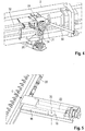
- Ein Detail einer Antriebseinrichtung des Schneidwerks gemäß
Figur 1 betrachtet von einer Rückseite des Schneidwerks, - Fig. 5:
- Ein Detail eines Kurbelgetriebes des Schneidwerks gemäß
Figur 1 in Zusammenwirkung mit einer Schwinge und - Fig. 6:
- Eine Draufsicht des Kurbelgetriebes gemäß
Figur 5 . - Ein Ausführungsbeispiel, das in den
Figuren 1 bis 6 dargestellt ist, umfasst ein erfindungsgemäßes Schneidwerk 1 eines Mähdreschers, das eine Tragwerksstruktur 2 aufweist. An der Tragwerkstruktur 2 ist ein Mähbalken 3 angeordnet, der sich in eine Breitenrichtung 10 des Schneidwerks 1 über eine gesamte Breite des Schneidwerks 1 erstreckt. Der Mähbalken 3 umfasst in dem gezeigten Beispiel zwei Mähsegmente 6, die wiederum jeweils zwei Mähmesser 5 aufweisen. Die Mähsegmente 6 erstrecken sich jeweils über eine halbe Breite 13 des Schneidwerks 1. Die Mähmesser 5 sind relativ zueinander bewegbar, wobei ein erstes Mähmesser 5 eines jeweiligen Mähsegments 6 als stehendes Untermesser und das zweite Mähmesser 5 mittels einer Antriebseinrichtung 4 des Schneidwerks 1 bewegbar ausgebildet sind. Insbesondere ist das bewegbare Mähmesser mittels der Antriebseinrichtung 4 oszillierend hin-und-her bewegbar, sodass sich in Zusammenwirkung mit dem feststehenden Mähmesser 5 die gewünschte Schneidwirkung ergibt. - Die Antriebseinrichtung 4 umfasst in dem gezeigten Beispiel eine Antriebswelle 30, die typischerweise von einer übergeordneten landwirtschaftlichen Erntemaschine des Schneidwerks 1 angetrieben wird. Die Antriebswelle 30 ist an einem rückseitigen Ende 27 des Schneidwerks 1 angeordnet und wirkt mit einem T-Getriebe 29 zusammen. Letzteres ergibt sich besonders gut anhand von
Figur 4 . Mittels des besagten T-Getriebes 29 wird ein mittels der Antriebswelle 30 zur Verfügung gestelltes Drehmoment auf zwei separate Abtriebswellen 31, 32 aufgeteilt. Die erste Abtriebswelle 32 wirkt mittelbar mit einer in den Figuren nicht dargestellten Einzugswalze zusammen, sodass die Einzugswalze drehantreibbar ist. Hierzu verfügt das Schneidwerk 1 im Bereich seines Seitenteils 35 über ein entsprechendes Riemengetriebe. Die zweite Abtriebswelle 31 wirkt ihrerseits unmittelbar mit einem Riemengetriebe 26 zusammen, das hier einen Verbundriemen 34 aufweist, der die Abtriebswelle 31 in Drehmoment übertragender Weise mit einer Gelenkwelle 25 verbindet. Letztere ergibt sich besonders gut vonFigur 5 , während sich der Aufbau der Antriebseinrichtung 4 insgesamt besonders gut anhand vonFigur 2 ergibt. Mittels der Gelenkwelle 25 wird das Drehmoment an ein Kurbelgetriebe 9 übertragen, das an einem vorderseitigen Ende 24 des Schneidwerks 1 angeordnet ist. Insbesondere ist das Kurbelgetriebe 9 in unmittelbarer Nähe zu dem ihm zugeordneten Mähsegment 6 angeordnet. Die Gelenkwelle 25 dient mithin dazu, das zur Verfügung gestellte Drehmoment von dem rückseitigen Ende 27 des Schneidwerks in Längsrichtung des Schneidwerks 1 zu dessen vorderseitigem Ende 24 zu übertragen. Die Gelenkwelle 25 ist entsprechend langgestreckt ausgebildet und weist hier eine Länge von 1350 mm auf. - Das hier gezeigte erfindungsgemäße Schneidwerk 1 verfügt über insgesamt zwei Kurbelgetrieben 9, die jeweils einem der Mähsegmente 6 zugeordnet sind. Erfindungsgemäß sind die Kurbelgetriebe 9 außermittig bezogen auf eine querseitige Mitte 12 des Schneidwerks 1 angeordnet, wobei sie sich jeweils in einem in Breitenrichtung 10 gemessenen Abstand 11 von der Mitte 12 befinden. Der Abstand 11 entspricht in dem gezeigten Beispiel jeweils ca. 40 % der halben Breite 13 des Schneidwerks 1. Die beiden Kurbelgetriebe 9 sind mittels einer Verbindungswelle 28 miteinander verbunden, mittels derer das mit der Gelenkwelle 25 dem ersten Kurbelgetriebe 9 zur Verfügung gestellte Drehmoment auf das andere Kurbelgetriebe 9 übertragbar ist. Auf diese Weise kann ein unmittelbarer Anschluss des zweiten Kurbelgetriebes 9 an eine eigene Gelenkwelle unterbleiben.
- Beide Kurbelgetriebe 9 sind unterhalb eines Schneidwerkstischs 7 des Schneidwerks 1 angeordnet. Dies ergibt sich besonders gut anhand der Darstellung gemäß
Figur 2 , die den Verlauf der Gelenkwelle 25 sowie den Installationsort der Kurbelgetriebe 9 verdeutlicht. Die Anordnung der Kurbelgetriebe 9 unterhalb des Schneidwerkstischs 7 ist besonders vorteilhaft, da die Tragwerksstruktur 2 kaum beeinflusst wird, insbesondere kaum eine Schwächung der letzteren zu beklagen ist. In Kombination mit der außermittigen Anordnung der Kurbelgetriebe 9 bezogen auf die querseitige Mitte 12 des Schneidwerks 1 wird hierdurch erreicht, dass eine Steifigkeit und Tragfähigkeit der Tragwerkstruktur 2 infolge der Anordnung der Kurbelgetriebe 9 kaum negativ beeinträchtigt wird. - Die Antriebseinrichtung 4 ist in ihrer Gesamtheit besonders gut anhand der vereinfachten Darstellung gemäß
Figur 3 erkennbar, die neben der Antriebseinrichtung 4 bzw. ihre einzelnen Komponenten lediglich noch den Mähbalken 3 darstellt. In Kombination mit den Darstellungen in denFiguren 5 und6 ergibt sich, dass die Kurbelgetriebe 9 des hier gezeigten erfindungsgemäßen Schneidwerks 1 jeweils einen Exzenter 14 aufweisen, der drehantreibbar an dem Kurbelgetriebe 9 gelagert ist. Die Konstruktion der Kurbelgetriebe 9 in Zusammenwirkung mit den Mähsegmenten 6 wird nachfolgende exemplarisch für das mit der Gelenkwelle 25 verbundene der Kurbelgetriebe 9 beschrieben. Die Funktionsweise gilt für das andere Kurbelgetriebe 9 analog. - Das Kurbelgetriebe 9 ist dazu geeignet, das mittels der Gelenkwelle 25 zur Verfügung gestellte Drehmoment in eine Rotationsbewegung des Exzenters 14 zu übersetzen. Der Exzenter 14 ist seinerseits mittels einer Koppelstange 23 mit einer neben dem Kurbelgetriebe 9 angeordneten Schwinge 16 gekoppelt. Der Exzenter 14 und die Koppelstange 23 bilden gemeinsam gewissermaßen die "Kurbel" des Kurbelgetriebes 9. Die Koppelstange 23 ist an ihrem dem Exzenter 14 abgewandten Ende an einer Anlenkstelle 15 mit der Schwinge 16 verbunden. Beide Enden der Koppelstange 23, das heißt zum einen an den Exzenter 14 und zum anderen an der Schwinge 16, sind jeweils gelenkig ausgebildet, sodass die rotierende Bewegung des Exzenters 14 in eine quasi lineare Bewegung der Anlenkstelle 15 übertragbar ist. Die Schwinge 16 weist zwei einander gegenüberliegende Endbereiche 17, 19 auf, wobei die Schwinge 16 an ihrem ersten Endbereich 17 unter Ausbildung eines Drehgelenks 18 an dem Schneidwerkstisch 7 des Schneidwerks 1 gelagert ist. An dem zweiten Endbereiche 19 ist die Schwinge 16 mittels eines Kopplungsmittels 20 in Kraft übertragender Weise mit dem Mähmesser 5 des dem Kurbelgetriebe 9 zugeordneten Mähsegments 6 verbunden, das bewegbar ausgebildet ist. Der Betrieb des Exzenters 14 des Kurbelgetriebes 9 führt angesichts dieser Anordnung dazu, dass die Schwinge 16 oszillierend um eine Gelenkachse 33 des Drehgelenks 18 hin-und-her geschwenkt wird, wodurch in gewünschter Weise eine gleichermaßen oszillierende Hin-und Her-Bewegung des zugeordneten Mähmessers 5 auftritt.
- Die Gelenkwelle 25 ist in dem gezeigten Beispiel teleskopierbar ausgebildet, sodass sich eine Länge 21 der Schwinge 16 verändern lässt. Dies ist in dem gezeigten Beispiel besonders vorteilhaft, da das Schneidwerk 1 über einen Tischausleger 8 verfügt, der in Längsrichtung des Schneidwerks 1, das heißt quer zu der Breitenrichtung 10, bewegbar ist. Mittels der teleskopierbaren Ausgestaltung der Gelenkwelle 25 ist die Möglichkeit gegeben, den Tischausleger 8 axial zwischen einer Vorstellung und einer Rückstellung zu verfahren, ohne dass die Kurbelgetriebe 9 ihre Funktionalität einbüßen.
- Die Anlenkstelle 15 der Koppelstange 23 an der Schwinge 16 befindet sich in dem gezeigten Beispiel in einem Abstand 22 von dem Kopplungsmittel 20. Dieser Abstand 22 beträgt in dem gezeigten Beispiel 25 % der gesamten Länge 21 der Schwinge 16. Die Anordnung der Anlenkstelle 15 in einem solchen, dem zweiten Endbereichen 19 zugewandten Bereich der Schwinge 16 führt dazu, dass auf die Koppelstange 23 einwirkende Kräfte niedriger sind. Die zur Verfügung stehende Schneidkraft des betroffenen Mähmessers 5 ist entsprechend stark ausgebildet. Eine Längsachse der Schwinge 16 ist zudem senkrecht zu einer Längsachse des ihr zugeordneten Mähmesser 5 angeordnet. Dies führt dazu, dass die Bewegung des Mähmessers 5 im Zuge des Betriebs des Kurbelgetriebes 9 sich fast ausschließlich parallel zu der Breitenrichtung 10 des Schneidwerks 1 erstreckt und kaum einen Bewegungsanteil aufweist, der sich in Längsrichtung, das heißt senkrecht zu der Breitenrichtung 10, erstreckt.
-
- 1
- Schneidwerk
- 2
- Tragwerksstruktur
- 3
- Mähbalken
- 4
- Antriebseinrichtung
- 5
- Mähmesser
- 6
- Mähsegment
- 7
- Schneidwerkstisch
- 8
- Tischausleger
- 9
- Kurbelgetriebe
- 10
- Breitenrichtung
- 11
- Abstand
- 12
- Mitte
- 13
- halbe Breite
- 14
- Exzenter
- 15
- Anlenkstelle
- 16
- Schwinge
- 17
- erster Endbereich
- 18
- Drehgelenk
- 19
- zweiter Endbereich
- 20
- Kopplungsmittel
- 21
- Länge
- 22
- Abstand
- 23
- Koppelstange
- 24
- vorderseitiges Ende
- 25
- Gelenkwelle
- 26
- Riemengetriebe
- 27
- rückseitiges Ende
- 28
- Verbindungswelle
- 29
- T-Getriebe
- 30
- Antriebswelle
- 31
- Abtriebswelle
- 32
- Abtriebswelle
- 33
- Gelenkachse
- 34
- Zahnriemen
- 35
- Seitenteil
Claims (15)
- Schneidwerk (1) für eine landwirtschaftliche Erntemaschine, insbesondere für einen Mähdrescher, umfassend- einen langgestreckten, sich in Breitenrichtung (10) des Schneidwerks (1) erstreckenden Mähbalken (3) sowie- eine mit dem Mähbalken (3) zusammenwirkende Antriebseinrichtung (4),wobei der Mähbalken (3) mindestens ein mit Mähmessern (5) versehenes Mähsegment (6) aufweist,
wobei die Mähmesser (5) des Mähsegments (6) mittelbar oder unmittelbar mittels der Antriebseinrichtung (4) derart relativ zueinander oszillierend antreibbar sind, dass zu erntende Pflanzen schneidbar sind,
dadurch gekennzeichnet, dass
die Antriebseinrichtung (4) mindestens ein Kurbelgetriebe (9) umfasst,
wobei das Kurbelgetriebe (9) außermittig bezogen auf das Schneidwerk (1) angeordnet ist und
wobei das Kurbelgetriebe (9) unterhalb eines Schneidwerkstischs (7) des Schneidwerks (1) angeordnet ist. - Schneidwerk (1) nach Anspruch 1, dadurch gekennzeichnet, dass ein seitlicher, parallel zur Breitenrichtung (10) des Schneidwerks (1) gemessener Abstand (11) zwischen dem mindestens einen Kurbelgetriebe (9) und einer querseitigen Mitte (12) des Schneidwerks (1) mindestens 20 %, vorzugsweise mindestens 30 %, weiter vorzugsweise mindestens 40 %, einer halben Breite (13) des Schneidwerks (1) beträgt.
- Schneidwerk (1) nach Anspruch 1 oder 2, gekennzeichnet durch eine Mehrzahl von Kurbelgetrieben (9), insbesondere zwei Kurbelgetriebe (9), wobei sämtliche Kurbelgetriebe (9) außermittig bezogen auf das Schneidwerk (1) angeordnet sind, wobei die Kurbelgetriebe (9) vorzugsweise symmetrisch bezogen auf eine querseitige Mitte (12) des Schneidwerks (1) angeordnet sind.
- Schneidwerk (1) nach einem der Ansprüche 1 bis 3, gekennzeichnet durch eine Mehrzahl von Kurbelgetrieben (9), insbesondere zwei Kurbelgetriebe (9), wobei sämtliche Kurbelgetriebe (9) unterhalb des Schneidwerkstischs (7) angeordnet sind.
- Schneidwerk (1) nach einem der Ansprüche 1 bis 4, dadurch gekennzeichnet, dass das Kurbelgetriebe (9) einen Exzenter (14) aufweist, der an einer Anlenkstelle (15) einer Schwinge (16) angelenkt ist, wobei die Schwinge (16) in einem ersten Endbereich (17) unter Ausbildung eines Drehgelenks (18) gelenkig gelagert und an ihrem gegenüberliegenden zweiten Endbereich (19) mittels eines Kopplungsmittels (20) mit mindestens einem der Mähmesser (5) gekoppelt ist, sodass das Mähmesser (5) mittels Antriebs des Exzenters (14) in eine oszillierende Bewegung versetzbar ist.
- Schneidwerk (1) nach Anspruch 5, dadurch gekennzeichnet, dass die Schwinge (16) langgestreckt ausgebildet ist, wobei vorzugsweise eine sich zwischen dem Drehgelenk (18) und dem Kopplungsmittel (20) erstreckende Länge (21) der Schwinge (16) mindestens 500 mm, vorzugsweise mindestens 600 mm, weiter vorzugsweise mindestens 700 mm, beträgt.
- Schneidwerk (1) nach Anspruch 5 oder 6, dadurch gekennzeichnet, dass die Anlenkstelle (15) des Exzenters (14) dem dem Kopplungsmittel (20) zugeordneten zweiten Endbereich (19) der Schwinge (16) zugeordnet ist, wobei vorzugsweise ein Abstand (22) zwischen dem Kopplungsmittel (20) und der Anlenkstelle (15) maximal 40 %, vorzugsweise maximal 30 %, weiter vorzugsweise maximal 20 %, einer Länge (21) der Schwinge (16) beträgt.
- Schneidwerk (1) nach einem der Ansprüche 1 bis 7, dadurch gekennzeichnet, dass das Kurbelgetriebe (9) an einem vorderseitigen Ende (24) des Schneidwerks (1) angeordnet ist, wobei vorzugsweise die Antriebseinrichtung (4) mindestens eine Gelenkwelle (25) aufweist, die mit dem Kurbelgetriebe (9) zusammenwirkt und sich senkrecht zu der Breitenrichtung (10) des Schneidwerks (1) erstreckt.
- Schneidwerk (1) nach Anspruch 8, dadurch gekennzeichnet, dass die Gelenkwelle (25) teleskopierbar, vorzugsweise doppelt teleskopierbar, ausgebildet ist.
- Schneidwerk (1) nach einem der Ansprüche 1 bis 9, dadurch gekennzeichnet, dass die Antriebseinrichtung (4) mindestens ein Riemengetriebe (26) aufweist, das vorzugsweise an einem rückseitigen Ende (27) des Schneidwerks (1) angeordnet ist.
- Schneidwerk (1) nach einem der Ansprüche 1 bis 10, gekennzeichnet durch eine Mehrzahl von Kurbelgetrieben (9), vorzugsweise zwei Kurbelgetriebe (9), sowie mindestens zwei Mähsegmente (6), wobei die Kurbelgetriebe (9) jeweils einem Mähsegment (6) zugeordnet sind und jeweils einen Exzenter (14) aufweisen, die gegeneinander phasenverschoben ausgebildet sind, vorzugsweise um einen Phasenwinkel von π.
- Schneidwerk (1) nach Anspruch 11, dadurch gekennzeichnet, dass die Kurbelgetriebe (9) untereinander mittels einer Verbindungswelle (28) miteinander verbunden sind, sodass ein auf eines der Kurbelgetriebe (9) übertragendes Drehmoment mittels der Verbindungswelle (28) an das/die weitere(n) Kurbelgetriebe (9) übertragbar ist, wobei sich die Verbindungswelle (28) vorzugsweise parallel zu der Breitenrichtung (10) des Schneidwerks (1) erstreckt.
- Schneidwerk (1) nach Anspruch 12, dadurch gekennzeichnet, dass mindestens eine Verbindungswelle (28) mindestens eine Schwungmasse aufweist.
- Schneidwerk (1) nach einem der Ansprüche 1 bis 13, dadurch gekennzeichnet, dass die Antriebseinrichtung (4) mindestens ein T-Getriebe (29) aufweist, mittels dessen ein mittels einer Antriebswelle (30) zur Verfügung gestelltes Drehmoment auf zwei Abtriebswellen (31, 32) aufteilbar ist, wobei vorzugsweise eine erste Abtriebswelle (31) zum zumindest mittelbaren Antrieb des mindestens einen Kurbelgetriebes (9) und die zweite Abtriebswelle (32) zum zumindest mittelbaren Antrieb mindestens einer Einzugswalze (33) des Schneidwerks (1) dient.
- Schneidwerk (1) nach einem der Ansprüche 1 bis 14, dadurch gekennzeichnet, dass der Schneidwerkstisch (7) einen Tischausleger (8) umfasst, der in eine Richtung senkrecht zu der Breitenrichtung (10) des Schneidwerks (1) zwischen einer maximal nach vorne ausgefahrenen Vorderstellung und einer maximal nach hinten eingefahrenen Rückstellung bewegbar ist.
Applications Claiming Priority (1)
| Application Number | Priority Date | Filing Date | Title |
|---|---|---|---|
| DE102019105635.7A DE102019105635A1 (de) | 2019-03-06 | 2019-03-06 | Schneidwerk für eine landwirtschaftliche Erntemaschine |
Publications (2)
| Publication Number | Publication Date |
|---|---|
| EP3704927A1 true EP3704927A1 (de) | 2020-09-09 |
| EP3704927B1 EP3704927B1 (de) | 2022-02-09 |
Family
ID=68835108
Family Applications (1)
| Application Number | Title | Priority Date | Filing Date |
|---|---|---|---|
| EP19214391.5A Active EP3704927B1 (de) | 2019-03-06 | 2019-12-09 | Schneidwerk für eine landwirtschaftliche erntemaschine |
Country Status (2)
| Country | Link |
|---|---|
| EP (1) | EP3704927B1 (de) |
| DE (1) | DE102019105635A1 (de) |
Citations (6)
| Publication number | Priority date | Publication date | Assignee | Title |
|---|---|---|---|---|
| US4198803A (en) * | 1976-08-13 | 1980-04-22 | White Motor Corporation Of Canada Limited | Cutterbar for a crop harvesting machine |
| DE102009040230A1 (de) * | 2009-09-07 | 2011-04-14 | Ludger Hellkuhl | Schneidvorrichtung für eine landwirtschaftliche Maschine |
| DE102010040870A1 (de) * | 2009-10-29 | 2011-05-05 | Deere & Company, Moline | Sich hin- und herbewegende Messeranordnung für ein landwirtschaftliches Gerät |
| US8011272B1 (en) * | 2010-04-28 | 2011-09-06 | Cnh America Llc | Dual flywheel axially compact epicyclical drive |
| DE102015106087A1 (de) * | 2015-04-21 | 2016-10-27 | Claas Hungaria Kft. | Schneidwerk |
| EP1935226B1 (de) | 2006-12-22 | 2017-09-13 | CNH Industrial Belgium nv | Kompakter Sichelantrieb für einen Kopf an einer Landwirtschaftsschneidmaschine |
-
2019
- 2019-03-06 DE DE102019105635.7A patent/DE102019105635A1/de active Pending
- 2019-12-09 EP EP19214391.5A patent/EP3704927B1/de active Active
Patent Citations (6)
| Publication number | Priority date | Publication date | Assignee | Title |
|---|---|---|---|---|
| US4198803A (en) * | 1976-08-13 | 1980-04-22 | White Motor Corporation Of Canada Limited | Cutterbar for a crop harvesting machine |
| EP1935226B1 (de) | 2006-12-22 | 2017-09-13 | CNH Industrial Belgium nv | Kompakter Sichelantrieb für einen Kopf an einer Landwirtschaftsschneidmaschine |
| DE102009040230A1 (de) * | 2009-09-07 | 2011-04-14 | Ludger Hellkuhl | Schneidvorrichtung für eine landwirtschaftliche Maschine |
| DE102010040870A1 (de) * | 2009-10-29 | 2011-05-05 | Deere & Company, Moline | Sich hin- und herbewegende Messeranordnung für ein landwirtschaftliches Gerät |
| US8011272B1 (en) * | 2010-04-28 | 2011-09-06 | Cnh America Llc | Dual flywheel axially compact epicyclical drive |
| DE102015106087A1 (de) * | 2015-04-21 | 2016-10-27 | Claas Hungaria Kft. | Schneidwerk |
Also Published As
| Publication number | Publication date |
|---|---|
| DE102019105635A1 (de) | 2020-09-10 |
| EP3704927B1 (de) | 2022-02-09 |
Similar Documents
| Publication | Publication Date | Title |
|---|---|---|
| DE69511739T2 (de) | Kreiselmäher mit Mähbalken und Traggestell | |
| DE2132217A1 (de) | Dreschkorb-Einstellvorrichtung bei Maehdreschern | |
| EP3706543B1 (de) | Schneidwerk für eine landwirtschaftliche erntemaschine | |
| EP2700294B1 (de) | Schneidwerk für eine selbstfahrende Erntemaschine | |
| EP0667186B1 (de) | Walzenmühle | |
| DE102015106087A1 (de) | Schneidwerk | |
| EP3628142A1 (de) | Schneidwerk für eine landwirtschaftliche erntemaschine sowie verfahren zum betrieb eines schneidwerks | |
| EP1133911B1 (de) | Vorrichtung zum Pflücken der Fruchtstände stängeliger Erntegüter | |
| DE2262826A1 (de) | Maehwerkhaspel mit zinkensteuerung | |
| DE2104564A1 (de) | Gras Erntemaschine | |
| DE102019002828B3 (de) | Mähmaschine | |
| EP3704927B1 (de) | Schneidwerk für eine landwirtschaftliche erntemaschine | |
| EP2661952A1 (de) | Heuwerbungsmaschine | |
| EP2700293B1 (de) | Getriebe für den Antrieb eines Mähmessers einer Erntemaschine | |
| DD158460A3 (de) | Lockerungs-und verteilvorrichtung an strohschuettlern | |
| EP3957151B1 (de) | Seitenschneidwerk | |
| DE102021118849B3 (de) | Portalschneidwerk | |
| DE102023117266A1 (de) | Landwirtschaftliche Mähmaschine | |
| EP3680320B1 (de) | Austragsvorrichtung für ein beschickungssystem zum bereitstellen von biomasse in einer biogasanlage | |
| DE69617611T2 (de) | Heuwerbungsmaschine | |
| EP2163149B1 (de) | Einzugsvorrichtung für ein Häckselaggregat eines Feldhäckslers | |
| DE19926826C2 (de) | Antrieb für eine Kolbensammelpresse für landwirtschaftliche Erntegüter | |
| EP1145620B1 (de) | Heuwerbungsmaschine | |
| EP3620043A1 (de) | Heuwerbungsmaschine, insbesondere kreiselschwader | |
| DE102005053060B4 (de) | Heuwerbungsmaschine |
Legal Events
| Date | Code | Title | Description |
|---|---|---|---|
| PUAI | Public reference made under article 153(3) epc to a published international application that has entered the european phase |
Free format text: ORIGINAL CODE: 0009012 |
|
| STAA | Information on the status of an ep patent application or granted ep patent |
Free format text: STATUS: THE APPLICATION HAS BEEN PUBLISHED |
|
| AK | Designated contracting states |
Kind code of ref document: A1 Designated state(s): AL AT BE BG CH CY CZ DE DK EE ES FI FR GB GR HR HU IE IS IT LI LT LU LV MC MK MT NL NO PL PT RO RS SE SI SK SM TR |
|
| AX | Request for extension of the european patent |
Extension state: BA ME |
|
| STAA | Information on the status of an ep patent application or granted ep patent |
Free format text: STATUS: REQUEST FOR EXAMINATION WAS MADE |
|
| 17P | Request for examination filed |
Effective date: 20210309 |
|
| RBV | Designated contracting states (corrected) |
Designated state(s): AL AT BE BG CH CY CZ DE DK EE ES FI FR GB GR HR HU IE IS IT LI LT LU LV MC MK MT NL NO PL PT RO RS SE SI SK SM TR |
|
| GRAP | Despatch of communication of intention to grant a patent |
Free format text: ORIGINAL CODE: EPIDOSNIGR1 |
|
| STAA | Information on the status of an ep patent application or granted ep patent |
Free format text: STATUS: GRANT OF PATENT IS INTENDED |
|
| INTG | Intention to grant announced |
Effective date: 20210813 |
|
| GRAS | Grant fee paid |
Free format text: ORIGINAL CODE: EPIDOSNIGR3 |
|
| GRAA | (expected) grant |
Free format text: ORIGINAL CODE: 0009210 |
|
| STAA | Information on the status of an ep patent application or granted ep patent |
Free format text: STATUS: THE PATENT HAS BEEN GRANTED |
|
| AK | Designated contracting states |
Kind code of ref document: B1 Designated state(s): AL AT BE BG CH CY CZ DE DK EE ES FI FR GB GR HR HU IE IS IT LI LT LU LV MC MK MT NL NO PL PT RO RS SE SI SK SM TR |
|
| REG | Reference to a national code |
Ref country code: GB Ref legal event code: FG4D Free format text: NOT ENGLISH |
|
| REG | Reference to a national code |
Ref country code: CH Ref legal event code: EP Ref country code: AT Ref legal event code: REF Ref document number: 1466931 Country of ref document: AT Kind code of ref document: T Effective date: 20220215 |
|
| REG | Reference to a national code |
Ref country code: DE Ref legal event code: R096 Ref document number: 502019003392 Country of ref document: DE |
|
| REG | Reference to a national code |
Ref country code: IE Ref legal event code: FG4D Free format text: LANGUAGE OF EP DOCUMENT: GERMAN |
|
| REG | Reference to a national code |
Ref country code: LT Ref legal event code: MG9D |
|
| REG | Reference to a national code |
Ref country code: NL Ref legal event code: MP Effective date: 20220209 |
|
| PG25 | Lapsed in a contracting state [announced via postgrant information from national office to epo] |
Ref country code: SE Free format text: LAPSE BECAUSE OF FAILURE TO SUBMIT A TRANSLATION OF THE DESCRIPTION OR TO PAY THE FEE WITHIN THE PRESCRIBED TIME-LIMIT Effective date: 20220209 Ref country code: RS Free format text: LAPSE BECAUSE OF FAILURE TO SUBMIT A TRANSLATION OF THE DESCRIPTION OR TO PAY THE FEE WITHIN THE PRESCRIBED TIME-LIMIT Effective date: 20220209 Ref country code: PT Free format text: LAPSE BECAUSE OF FAILURE TO SUBMIT A TRANSLATION OF THE DESCRIPTION OR TO PAY THE FEE WITHIN THE PRESCRIBED TIME-LIMIT Effective date: 20220609 Ref country code: NO Free format text: LAPSE BECAUSE OF FAILURE TO SUBMIT A TRANSLATION OF THE DESCRIPTION OR TO PAY THE FEE WITHIN THE PRESCRIBED TIME-LIMIT Effective date: 20220509 Ref country code: NL Free format text: LAPSE BECAUSE OF FAILURE TO SUBMIT A TRANSLATION OF THE DESCRIPTION OR TO PAY THE FEE WITHIN THE PRESCRIBED TIME-LIMIT Effective date: 20220209 Ref country code: LT Free format text: LAPSE BECAUSE OF FAILURE TO SUBMIT A TRANSLATION OF THE DESCRIPTION OR TO PAY THE FEE WITHIN THE PRESCRIBED TIME-LIMIT Effective date: 20220209 Ref country code: HR Free format text: LAPSE BECAUSE OF FAILURE TO SUBMIT A TRANSLATION OF THE DESCRIPTION OR TO PAY THE FEE WITHIN THE PRESCRIBED TIME-LIMIT Effective date: 20220209 Ref country code: ES Free format text: LAPSE BECAUSE OF FAILURE TO SUBMIT A TRANSLATION OF THE DESCRIPTION OR TO PAY THE FEE WITHIN THE PRESCRIBED TIME-LIMIT Effective date: 20220209 Ref country code: BG Free format text: LAPSE BECAUSE OF FAILURE TO SUBMIT A TRANSLATION OF THE DESCRIPTION OR TO PAY THE FEE WITHIN THE PRESCRIBED TIME-LIMIT Effective date: 20220509 |
|
| PG25 | Lapsed in a contracting state [announced via postgrant information from national office to epo] |
Ref country code: PL Free format text: LAPSE BECAUSE OF FAILURE TO SUBMIT A TRANSLATION OF THE DESCRIPTION OR TO PAY THE FEE WITHIN THE PRESCRIBED TIME-LIMIT Effective date: 20220209 Ref country code: LV Free format text: LAPSE BECAUSE OF FAILURE TO SUBMIT A TRANSLATION OF THE DESCRIPTION OR TO PAY THE FEE WITHIN THE PRESCRIBED TIME-LIMIT Effective date: 20220209 Ref country code: GR Free format text: LAPSE BECAUSE OF FAILURE TO SUBMIT A TRANSLATION OF THE DESCRIPTION OR TO PAY THE FEE WITHIN THE PRESCRIBED TIME-LIMIT Effective date: 20220510 Ref country code: FI Free format text: LAPSE BECAUSE OF FAILURE TO SUBMIT A TRANSLATION OF THE DESCRIPTION OR TO PAY THE FEE WITHIN THE PRESCRIBED TIME-LIMIT Effective date: 20220209 |
|
| PG25 | Lapsed in a contracting state [announced via postgrant information from national office to epo] |
Ref country code: IS Free format text: LAPSE BECAUSE OF FAILURE TO SUBMIT A TRANSLATION OF THE DESCRIPTION OR TO PAY THE FEE WITHIN THE PRESCRIBED TIME-LIMIT Effective date: 20220609 |
|
| PG25 | Lapsed in a contracting state [announced via postgrant information from national office to epo] |
Ref country code: SM Free format text: LAPSE BECAUSE OF FAILURE TO SUBMIT A TRANSLATION OF THE DESCRIPTION OR TO PAY THE FEE WITHIN THE PRESCRIBED TIME-LIMIT Effective date: 20220209 Ref country code: SK Free format text: LAPSE BECAUSE OF FAILURE TO SUBMIT A TRANSLATION OF THE DESCRIPTION OR TO PAY THE FEE WITHIN THE PRESCRIBED TIME-LIMIT Effective date: 20220209 Ref country code: RO Free format text: LAPSE BECAUSE OF FAILURE TO SUBMIT A TRANSLATION OF THE DESCRIPTION OR TO PAY THE FEE WITHIN THE PRESCRIBED TIME-LIMIT Effective date: 20220209 Ref country code: EE Free format text: LAPSE BECAUSE OF FAILURE TO SUBMIT A TRANSLATION OF THE DESCRIPTION OR TO PAY THE FEE WITHIN THE PRESCRIBED TIME-LIMIT Effective date: 20220209 Ref country code: DK Free format text: LAPSE BECAUSE OF FAILURE TO SUBMIT A TRANSLATION OF THE DESCRIPTION OR TO PAY THE FEE WITHIN THE PRESCRIBED TIME-LIMIT Effective date: 20220209 Ref country code: CZ Free format text: LAPSE BECAUSE OF FAILURE TO SUBMIT A TRANSLATION OF THE DESCRIPTION OR TO PAY THE FEE WITHIN THE PRESCRIBED TIME-LIMIT Effective date: 20220209 |
|
| REG | Reference to a national code |
Ref country code: DE Ref legal event code: R097 Ref document number: 502019003392 Country of ref document: DE |
|
| PG25 | Lapsed in a contracting state [announced via postgrant information from national office to epo] |
Ref country code: AL Free format text: LAPSE BECAUSE OF FAILURE TO SUBMIT A TRANSLATION OF THE DESCRIPTION OR TO PAY THE FEE WITHIN THE PRESCRIBED TIME-LIMIT Effective date: 20220209 |
|
| PLBE | No opposition filed within time limit |
Free format text: ORIGINAL CODE: 0009261 |
|
| STAA | Information on the status of an ep patent application or granted ep patent |
Free format text: STATUS: NO OPPOSITION FILED WITHIN TIME LIMIT |
|
| 26N | No opposition filed |
Effective date: 20221110 |
|
| PG25 | Lapsed in a contracting state [announced via postgrant information from national office to epo] |
Ref country code: SI Free format text: LAPSE BECAUSE OF FAILURE TO SUBMIT A TRANSLATION OF THE DESCRIPTION OR TO PAY THE FEE WITHIN THE PRESCRIBED TIME-LIMIT Effective date: 20220209 |
|
| P01 | Opt-out of the competence of the unified patent court (upc) registered |
Effective date: 20230516 |
|
| PG25 | Lapsed in a contracting state [announced via postgrant information from national office to epo] |
Ref country code: IT Free format text: LAPSE BECAUSE OF FAILURE TO SUBMIT A TRANSLATION OF THE DESCRIPTION OR TO PAY THE FEE WITHIN THE PRESCRIBED TIME-LIMIT Effective date: 20220209 |
|
| REG | Reference to a national code |
Ref country code: CH Ref legal event code: PL |
|
| PG25 | Lapsed in a contracting state [announced via postgrant information from national office to epo] |
Ref country code: LU Free format text: LAPSE BECAUSE OF NON-PAYMENT OF DUE FEES Effective date: 20221209 |
|
| PG25 | Lapsed in a contracting state [announced via postgrant information from national office to epo] |
Ref country code: LI Free format text: LAPSE BECAUSE OF NON-PAYMENT OF DUE FEES Effective date: 20221231 Ref country code: IE Free format text: LAPSE BECAUSE OF NON-PAYMENT OF DUE FEES Effective date: 20221209 Ref country code: CH Free format text: LAPSE BECAUSE OF NON-PAYMENT OF DUE FEES Effective date: 20221231 |
|
| PG25 | Lapsed in a contracting state [announced via postgrant information from national office to epo] |
Ref country code: FR Free format text: LAPSE BECAUSE OF NON-PAYMENT OF DUE FEES Effective date: 20221231 |
|
| PG25 | Lapsed in a contracting state [announced via postgrant information from national office to epo] |
Ref country code: CY Free format text: LAPSE BECAUSE OF FAILURE TO SUBMIT A TRANSLATION OF THE DESCRIPTION OR TO PAY THE FEE WITHIN THE PRESCRIBED TIME-LIMIT Effective date: 20220209 |
|
| PG25 | Lapsed in a contracting state [announced via postgrant information from national office to epo] |
Ref country code: MK Free format text: LAPSE BECAUSE OF FAILURE TO SUBMIT A TRANSLATION OF THE DESCRIPTION OR TO PAY THE FEE WITHIN THE PRESCRIBED TIME-LIMIT Effective date: 20220209 Ref country code: HU Free format text: LAPSE BECAUSE OF FAILURE TO SUBMIT A TRANSLATION OF THE DESCRIPTION OR TO PAY THE FEE WITHIN THE PRESCRIBED TIME-LIMIT; INVALID AB INITIO Effective date: 20191209 |
|
| PG25 | Lapsed in a contracting state [announced via postgrant information from national office to epo] |
Ref country code: MC Free format text: LAPSE BECAUSE OF FAILURE TO SUBMIT A TRANSLATION OF THE DESCRIPTION OR TO PAY THE FEE WITHIN THE PRESCRIBED TIME-LIMIT Effective date: 20220209 |
|
| PG25 | Lapsed in a contracting state [announced via postgrant information from national office to epo] |
Ref country code: MC Free format text: LAPSE BECAUSE OF FAILURE TO SUBMIT A TRANSLATION OF THE DESCRIPTION OR TO PAY THE FEE WITHIN THE PRESCRIBED TIME-LIMIT Effective date: 20220209 |
|
| GBPC | Gb: european patent ceased through non-payment of renewal fee |
Effective date: 20231209 |
|
| PG25 | Lapsed in a contracting state [announced via postgrant information from national office to epo] |
Ref country code: MT Free format text: LAPSE BECAUSE OF FAILURE TO SUBMIT A TRANSLATION OF THE DESCRIPTION OR TO PAY THE FEE WITHIN THE PRESCRIBED TIME-LIMIT Effective date: 20220209 |
|
| PG25 | Lapsed in a contracting state [announced via postgrant information from national office to epo] |
Ref country code: GB Free format text: LAPSE BECAUSE OF NON-PAYMENT OF DUE FEES Effective date: 20231209 |
|
| PG25 | Lapsed in a contracting state [announced via postgrant information from national office to epo] |
Ref country code: GB Free format text: LAPSE BECAUSE OF NON-PAYMENT OF DUE FEES Effective date: 20231209 |
|
| PG25 | Lapsed in a contracting state [announced via postgrant information from national office to epo] |
Ref country code: TR Free format text: LAPSE BECAUSE OF FAILURE TO SUBMIT A TRANSLATION OF THE DESCRIPTION OR TO PAY THE FEE WITHIN THE PRESCRIBED TIME-LIMIT Effective date: 20220209 |
|
| PGFP | Annual fee paid to national office [announced via postgrant information from national office to epo] |
Ref country code: DE Payment date: 20251211 Year of fee payment: 7 |
|
| PGFP | Annual fee paid to national office [announced via postgrant information from national office to epo] |
Ref country code: BE Payment date: 20251219 Year of fee payment: 7 |
|
| REG | Reference to a national code |
Ref country code: AT Ref legal event code: MM01 Ref document number: 1466931 Country of ref document: AT Kind code of ref document: T Effective date: 20241209 |
|
| PG25 | Lapsed in a contracting state [announced via postgrant information from national office to epo] |
Ref country code: AT Free format text: LAPSE BECAUSE OF NON-PAYMENT OF DUE FEES Effective date: 20241209 |
|
| PGFP | Annual fee paid to national office [announced via postgrant information from national office to epo] |
Ref country code: AT Payment date: 20260410 Year of fee payment: 5 |