EP3704786B1 - Abschlusseinheit - Google Patents
Abschlusseinheit Download PDFInfo
- Publication number
- EP3704786B1 EP3704786B1 EP18783049.2A EP18783049A EP3704786B1 EP 3704786 B1 EP3704786 B1 EP 3704786B1 EP 18783049 A EP18783049 A EP 18783049A EP 3704786 B1 EP3704786 B1 EP 3704786B1
- Authority
- EP
- European Patent Office
- Prior art keywords
- current
- electrical steel
- shielding
- termination unit
- contributing
- Prior art date
- Legal status (The legal status is an assumption and is not a legal conclusion. Google has not performed a legal analysis and makes no representation as to the accuracy of the status listed.)
- Active
Links
Images


Classifications
-
- C—CHEMISTRY; METALLURGY
- C23—COATING METALLIC MATERIAL; COATING MATERIAL WITH METALLIC MATERIAL; CHEMICAL SURFACE TREATMENT; DIFFUSION TREATMENT OF METALLIC MATERIAL; COATING BY VACUUM EVAPORATION, BY SPUTTERING, BY ION IMPLANTATION OR BY CHEMICAL VAPOUR DEPOSITION, IN GENERAL; INHIBITING CORROSION OF METALLIC MATERIAL OR INCRUSTATION IN GENERAL
- C23C—COATING METALLIC MATERIAL; COATING MATERIAL WITH METALLIC MATERIAL; SURFACE TREATMENT OF METALLIC MATERIAL BY DIFFUSION INTO THE SURFACE, BY CHEMICAL CONVERSION OR SUBSTITUTION; COATING BY VACUUM EVAPORATION, BY SPUTTERING, BY ION IMPLANTATION OR BY CHEMICAL VAPOUR DEPOSITION, IN GENERAL
- C23C14/00—Coating by vacuum evaporation, by sputtering or by ion implantation of the coating forming material
- C23C14/22—Coating by vacuum evaporation, by sputtering or by ion implantation of the coating forming material characterised by the process of coating
- C23C14/34—Sputtering
- C23C14/3407—Cathode assembly for sputtering apparatus, e.g. Target
-
- H—ELECTRICITY
- H01—ELECTRIC ELEMENTS
- H01J—ELECTRIC DISCHARGE TUBES OR DISCHARGE LAMPS
- H01J37/00—Discharge tubes with provision for introducing objects or material to be exposed to the discharge, e.g. for the purpose of examination or processing thereof
- H01J37/32—Gas-filled discharge tubes
- H01J37/34—Gas-filled discharge tubes operating with cathodic sputtering
- H01J37/3411—Constructional aspects of the reactor
- H01J37/3435—Target holders (includes backing plates and endblocks)
-
- H—ELECTRICITY
- H02—GENERATION; CONVERSION OR DISTRIBUTION OF ELECTRIC POWER
- H02K—DYNAMO-ELECTRIC MACHINES
- H02K11/00—Structural association of dynamo-electric machines with electric components or with devices for shielding, monitoring or protection
- H02K11/01—Structural association of dynamo-electric machines with electric components or with devices for shielding, monitoring or protection for shielding from electromagnetic fields, i.e. structural association with shields
- H02K11/014—Shields associated with stationary parts, e.g. stator cores
-
- C—CHEMISTRY; METALLURGY
- C23—COATING METALLIC MATERIAL; COATING MATERIAL WITH METALLIC MATERIAL; CHEMICAL SURFACE TREATMENT; DIFFUSION TREATMENT OF METALLIC MATERIAL; COATING BY VACUUM EVAPORATION, BY SPUTTERING, BY ION IMPLANTATION OR BY CHEMICAL VAPOUR DEPOSITION, IN GENERAL; INHIBITING CORROSION OF METALLIC MATERIAL OR INCRUSTATION IN GENERAL
- C23C—COATING METALLIC MATERIAL; COATING MATERIAL WITH METALLIC MATERIAL; SURFACE TREATMENT OF METALLIC MATERIAL BY DIFFUSION INTO THE SURFACE, BY CHEMICAL CONVERSION OR SUBSTITUTION; COATING BY VACUUM EVAPORATION, BY SPUTTERING, BY ION IMPLANTATION OR BY CHEMICAL VAPOUR DEPOSITION, IN GENERAL
- C23C14/00—Coating by vacuum evaporation, by sputtering or by ion implantation of the coating forming material
- C23C14/22—Coating by vacuum evaporation, by sputtering or by ion implantation of the coating forming material characterised by the process of coating
- C23C14/34—Sputtering
- C23C14/35—Sputtering by application of a magnetic field, e.g. magnetron sputtering
Definitions
- EP3193432 discloses a stator for an electric motor which comprises a cancel coil extending in a stator axial direction and which constitutes one or more closed circuits. Thanks to the cancel coil, an unbalanced magnetic flux will be reduced and electrical corrosion of bearings in the cancel coil will be suppressed.
- a more compact termination unit can be created which is suitable for rotating a target and for transferring electrical power to the target. It is thereby advantageous that the varying non-contributing magnetic field generated by the varying current to power the target is significantly reduced by the shielding winding.
- At least one other current can be applied, which has a different topology and of which the effect is not significantly mitigated.
- selective mitigation of the effects is possible and for example only those effects may be mitigated which do not contribute to the operation of the device and/or which result in energy losses in the component comprising electrical steel.
- the shielding element is configured such that when a neighboring varying current would be applied which results in a varying non-contributing magnetic field through the electrical steel, which is not contributing to the function of the device, this neighboring varying non-contributing magnetic field results in a net magnetic flux through the shielding element, and this neighboring varying current results in a current through the at least one shielding element which results in a magnetic field which counteracts the non-contributing magnetic field.
- a potential non-contributing magnetic field generated by a potential neighboring varying current (e.g. through a neighboring current transfer means), through the electrical steel is smaller than would be the case when no shielding element is present.
- the neighboring current creates an EMF in the shielding element resulting in a current through the at least one shielding element which results in a magnetic field which counteracts the non-contributing magnetic field. This current counteracts and therefore reduces the non-contributing magnetic field.
- the non-contributing magnetic field may be generated by an external magnetizing current.
- a specific non-contributing magnetic field is reduced by the presence of the shielding winding. This is achieved by a shielding winding which is configured such that the varying non-contributing magnetic field results in a net magnetic flux through the shielding element. Other magnetic fields which do not result in a net magnetic flux through the shielding element will not be reduced.
- the at least one shielding element is a shielding winding which circumvents at least a part of the at least one component comprising electrical steel such that a(varying) non-contributing magnetic field, which is not contributing to the operation of the device, results in a net magnetic flux through shielding winding.
- the at least one component comprising electrical steel is adapted for guiding a contributing magnetic field contributing to the function of the device, wherein the at least one shielding element is positioned such that substantially no net magnetic flux through the shielding element originates from the contributing magnetic field.
- the operation of the device is not significantly or even not affected by the shielding element. This is achieved by arranging the at least one shielding element such that it does not substantially influence the contributing magnetic field.
- the shielding element is a shielding winding.
- the at least one shielding winding is positioned such that a surface of one winding is substantially orthogonal to a direction in which the magnetic field is contributing to the operation of the device.
- the transfer means for transferring power to an external device, crosses a circumference of the component comprising the electrical steel.
- the transfer means is adapted for transferring the current in a unipolar direction through the at least one component comprising electrical steel (no return path through the component).
- the transfer means is configured such that the transfer means crosses a circumference of the component comprising the electrical steel, and such that a return path of the transfer means is outside the at least one component comprising electrical steel.
- the transfer means is thereby configured such that, if an AC current is applied through the transfer means this implies that a unipolar AC current flows through the at least one component comprising electrical steel.
- the unipolar current will result in a magnetic field in the electrical steel. It is an advantage of embodiments of the present invention that this non-contributing magnetic field is compensated for by the shielding element.
- the component comprising electrical steel has a toroidal shape
- the at least one shielding element is a shielding winding which is substantially toroidally wound around the at least one component comprising electrical steel.
- the at least one shielding element is a shielding winding which is short-circuited.
- the at least one shielding element is a shielding winding is loaded by an impedance.
- the at least one shielding element is sunken and/or embedded in the at least one component comprising electrical steel.
- this may be a shielding winding. It is an advantage of embodiments of the previous claims that the at least one shielding element does not form a mechanical hindrance in the device and/or for the operation of the device.
- the at least one shielding element is positioned where the varying non-contributing magnetic fields are expected.
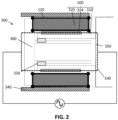
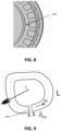
- FIG. 2 shows a schematic drawing of the same termination unit as the termination unit in FIG. 1 .
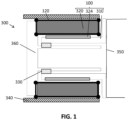
- the current transfer means 140 is indicated by the dashed line. It comprises the static part 360 of the termination unit, the brushes 330, and the rotating part 310 which is connected with the target 350.
- FIG. 2 also shows a wiring scheme for closing the current loop.
- the (unipolar) current transfer forms a closed circuitry around the component comprising electrical steel.
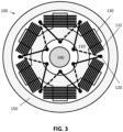
- the same shielding element may be applied to the component 324, holding the magnet configuration of the rotor.
- the same losses and heating phenomena may apply to this part as well and the shielding element is an effective method of shielding the potential external current while the functionality of the rotor is not being affected substantially.
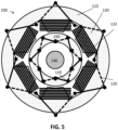
- Such a shielding element around the rotor of a motor is also illustrated in FIG. 5 .
- the termination unit comprises a current transfer means that carries a unipolar current through a component comprising electrical steel.
- the latter component is used for applying a rotational movement to the target (or to the magnetic bar) connected to the termination unit.
- This current transfer means is electrically isolated from the device 100 (e.g. from the motor, bearing or supporting structure) in order to enforce the current as a unipolar current through the component containing electrical steel.
- the total voltage drop (product of induced current and the AC resistance) is preferably below 1.0V to limit the losses inside the electrical steel. This is advantageous because the resulting voltage drop will be in correspondence with a generated ring flux inside the electrical steel.
- a shielding element e.g. winding
- a low leakage flux is realized with a low leakage flux.
- the shielding element is configured such that when a neighboring varying current (having the first topology) would be applied which results in a varying non-contributing magnetic field through the electrical steel, which is not contributing to the function of the device, this varying non-contributing magnetic field results in a net magnetic flux through the shielding element, and this neighboring varying current results in a current through the at least one shielding element which counteracts the non-contributing magnetic field.
- the neighboring varying current may be carried by a neighboring current transfer means having the first topology.
- the shielding element is a shielding winding.
- the shielding winding can for example be a single wire (being of any shape), a woven cable, a non-woven cable or a Litze cable.
- the neighboring current transfer means may be next to the component comprising electrical steel or it may go through the component comprising electrical steel.
- Electrical steel thereby is an iron alloy. It may be tailored to produce specific magnetic properties such as a small hysteresis area resulting in low power loss per cycle.
- the electrical steel may comprise other materials like ferrites, laminations, and high permeability materials.
- the non-contributing magnetic field may be generated by an external current not intended to contribute to the useful operation of the device.
- the current may for example flow over a current carrying conductor 140.
- the current carrying conductor may be in the neighborhood of the electrical steel component. This means it may be next to the electrical steel component or it may be surrounded by the electrical steel component.
- f is the frequency of the magnetic field variation and B is the magnetic flux density. This may be caused by an external current not contributing to the useful operation of the device.
- B is proportional to the current in the non-saturating working domain of the electrical steel, the losses will be proportional to the square of the current.
- the magnetic field is transferred from one side of the component comprising the electrical steel to the other side, creating the effect as if no electrical steel is present for the external current not intended to contribute to the useful operation of the device.
- the at least one component 110 comprising electrical steel is adapted for guiding a contributing magnetic field for operating the device 100. This may for example be the case for a transformer or a motor.
- the at least one shielding winding is positioned such that substantially no net integrated magnetic flux through the shielding winding originates from the contributing magnetic field.
- the potential presence of a non-contributing magnetic field has a flux path that is different from the contributing field.
- the at least one shielding winding may be short circuited or it may be loaded by an impedance.
- This may for example be a resistance, a capacitance, an inductance, or a combination of these elements.
- the device 100 is a motor.
- a motor may for example be a DC motor, an AC motor, a servo-motor, a stepper motor, a brushless DC motor, a reluctance motor, a torque motor.
- Adding magnetic reluctance inside the continuous core of the stator is an effective means in reducing the flux density generated by a potential unipolar external current, traversing the internal perimeter of the electrical steel. This can be seen from the equations that result when adding an airgap in the flux path inside electrical steel.
- Magnetic reluctance can be added into the electrical steel of a stator by introducing at least one 'airgap' or slit (filled with a non-magnetic material that can be conducting, but should be isolated from the electrical steel if the latter is conducting).
- a complete cut-out in the core of the electrical steel FIG.8
- partly slits can be made to create the same effect ( FIG.10 ).
- electrical steel when electrical steel consists of a stacked lamination assembly, it can be stacked in such a way that slit is located for many laminations at the same position, and then subsequent stacking can rotate the slit location to another location. This process can be done several times. When everything is fixed together, some substantial mechanical stiffness will result.
- the thickness of the shielding material should be at least three times the skin depth of the surface currents, as determined by the frequency content of the potential external alternating current. In that situation, no alternating magnetic field will be found at the inside of the closed shielding, hence no losses will be present in the electrical steel.
- the potential external current can pass through the shielded electrical steel as a unipolar current. In that case, a donut based hole must be provided in the shielding, so that the conductor with a unipolar current can pass through the shielding, the latter still forming a closed structure.
- the external return current is found in a conductor outside the shielded structure.
- a Faraday shielding is also very universal: it will shield the presence of every external current from the electrical steel at the inside of the shielding structure. In practice, the shielding is preferably only effective for a specific topology of the conductors carrying the potential external non-contributing current.
- the shielding element is configured such that it only counteracts the non-contributing magnetic field, but does not affect the contributing magnetic field of the motor. In this way, the shielding element can be confined to a fixed part on the stator and on the rotor only, removing the problem of the mechanical feed-through in the Faraday shielding.
- the device is a motor and the current transfer means is a conductor along the central axis of the motor which is adapted for carrying a current for powering an external device.
- the varying (e.g. alternating) part of this current has the properties that it will create unwanted excessive magnetic losses (hysteresis losses and eddy current losses) inside the electrical steel.
- the at least one shielding element e.g. winding
- the at least one shielding element is applied such that it does not counter-act the magnetic field of the normal motor operation (hence the motor windings do not induce voltages in this at least one shielding winding), but opposes the field created by the central axial current component.
- the at least one shielding winding is short-circuited, so that by definition, no magnetic field can be built-up for the flux density created by the potential external current. In practice, this alternating non-contributing magnetic field is strongly reduced because of the presence of the at least one shielding winding, and this results in a major drop of the magnetic losses inside the electrical steel as this is proportional to the square of the magnetic flux density.
Landscapes
- Chemical & Material Sciences (AREA)
- Engineering & Computer Science (AREA)
- Physics & Mathematics (AREA)
- Metallurgy (AREA)
- Organic Chemistry (AREA)
- Chemical Kinetics & Catalysis (AREA)
- Materials Engineering (AREA)
- Mechanical Engineering (AREA)
- Plasma & Fusion (AREA)
- Analytical Chemistry (AREA)
- Electromagnetism (AREA)
- Power Engineering (AREA)
- Iron Core Of Rotating Electric Machines (AREA)
- Motor Or Generator Frames (AREA)
- Physical Vapour Deposition (AREA)
- Separation Using Semi-Permeable Membranes (AREA)
- Input Circuits Of Receivers And Coupling Of Receivers And Audio Equipment (AREA)
- Coupling Device And Connection With Printed Circuit (AREA)
- Shielding Devices Or Components To Electric Or Magnetic Fields (AREA)
Claims (10)
- Eine Abschlusseinheit (300) für ein Aufdampfsystem, wobei die Abschlusseinheit einen Elektromotor (100) umfasst, wobei der Elektromotor umfasstmindestens eine Komponente (110), die Elektrostahl umfasst,wobei der Elektromotor einen Stator (320), und einen Rotor (310) umfasst, wobei der Stator (320) die mindestens eine Komponente umfasst, die Elektrostahl (110) umfasst, und/oder der Rotor (310) die mindestens eine Komponente umfasst, die Elektrostahl umfasst, und wobei der Motor konfiguriert ist, sodass ein Strom an den Elektromotor angelegt werden kann, was zu einem beitragenden Magnetfeld führt, was zu einer Drehmomentkraft zwischen dem Stator und dem Rotor führt, sodass der Motor ein Ziel (350), wenn es montiert ist, oder einen mit der Abschlusseinheit verbundenen Magnetstab drehen kann, unddadurch gekennzeichnet, dass die Vorrichtung (100) ein Stromübertragungsmittel (140) umfasst, das konfiguriert ist, sodass es einen Umfang der mindestens einen Komponente kreuzt, die Elektrostahl (110) umfasst, und wobei das Stromübertragungsmittel zum Übertragen von Leistung zum Ziel (350), wenn es an der Abschlusseinheit montiert ist, konfiguriert ist, und wobei die Vorrichtung mindestens ein elektrisch leitfähiges Abschirmelement (120) umfasst, das konfiguriert ist, sodass- wenn ein Strom an das Stromübertragungsmittel angelegt werden würde, eine Wirkung des Stroms auf die mindestens eine Komponente (110), die Elektrostahl umfasst, die nicht zur Drehmomentkraft des Elektromotors beiträgt, durch einen Strom durch das Abschirmelement (120) hindurch abgeschwächt wird, was zu einem entgegenwirkenden Feld im Abschirmelement führt.
- Eine Abschlusseinheit (300) nach Anspruch 1, wobei das Abschirmelement konfiguriert ist, sodasswenn ein benachbarter sich verändernder Strom angelegt werden würde, was zu einem sich verändernden nicht beitragenden Magnetfeld durch den Elektrostahl hindurch führt, das nicht zur Funktion der Vorrichtung beiträgt,das benachbarte, sich verändernde Magnetfeld zu einem Netto-Magnetfluss durch das Abschirmelement hindurch führt,und dieser benachbarte sich verändernde Strom zu einem Strom durch das mindestens eine Abschirmelement hindurch führt, was zu einem Magnetfeld führt, das dem nicht beitragenden Magnetfeld in der mindestens einen Komponente (110), die Elektrostahl umfasst, entgegenwirkt.
- Eine Abschlusseinheit (300) nach einem der vorstehenden Ansprüche, wobei die mindestens eine Komponente (110), die Elektrostahl umfasst, zum Führen eines beitragenden Magnetfelds, das zur Drehmomentkraft des Elektromotors (100) beiträgt, konfiguriert ist, wobei das mindestens eine Abschirmelement positioniert ist, sodass im Wesentlichen kein Netto-Magnetfluss durch das Abschirmelement hindurch aus dem beitragenden Magnetfeld stammt.
- Eine Abschlusseinheit (300) nach einem der vorstehenden Ansprüche, wobei die Komponente (110), die Elektrostahl umfasst, eine torusförmige Form aufweist, und wobei das mindestens eine Abschirmelement eine Abschirmwicklung ist, die im Wesentlichen torusförmig um die mindestens eine Komponente, die Elektrostahl umfasst, gewickelt ist.
- Eine Abschlusseinheit (300) nach einem der vorstehenden Ansprüche, wobei das mindestens eine Abschirmelement eine Abschirmwicklung (120) ist, die kurzgeschlossen ist.
- Eine Abschlusseinheit (300) nach einem der vorstehenden Ansprüche, wobei das mindestens eine Abschirmelement eine Abschirmwicklung ist, die durch eine Impedanz geladen ist.
- Eine Abschlusseinheit (300) nach einem der vorstehenden Ansprüche, wobei das mindestens eine Abschirmelement in die mindestens eine Komponente, die Elektrostahl umfasst versenkt und/oder eingebettet ist.
- Eine Abschlusseinheit (300) nach einem der vorstehenden Ansprüche, wobei die Abschlusseinheit Dichtungsmittel umfasst.
- Eine Abschlusseinheit (300) nach einem der vorstehenden Ansprüche, wobei das Stromübertragungsmittel (140) eine Mittelachse durch die Vorrichtung hindurch umfasst.
- Eine Abschlusseinheit (300) nach einem der vorstehenden Ansprüche, wobei die Abschlusseinheit eine Steuereinheit umfasst, die zum Anlegen von Gleichstrom durch das mindestens eine Abschirmelement (120) hindurch angepasst ist, um ein nicht beitragendes Magnetfeld zu erzeugen.
Applications Claiming Priority (2)
| Application Number | Priority Date | Filing Date | Title |
|---|---|---|---|
| BE201705791 | 2017-11-01 | ||
| PCT/EP2018/078124 WO2019086236A1 (en) | 2017-11-01 | 2018-10-15 | Termination unit |
Publications (3)
| Publication Number | Publication Date |
|---|---|
| EP3704786A1 EP3704786A1 (de) | 2020-09-09 |
| EP3704786B1 true EP3704786B1 (de) | 2025-06-25 |
| EP3704786C0 EP3704786C0 (de) | 2025-06-25 |
Family
ID=61156902
Family Applications (1)
| Application Number | Title | Priority Date | Filing Date |
|---|---|---|---|
| EP18783049.2A Active EP3704786B1 (de) | 2017-11-01 | 2018-10-15 | Abschlusseinheit |
Country Status (8)
| Country | Link |
|---|---|
| US (1) | US11365474B2 (de) |
| EP (1) | EP3704786B1 (de) |
| JP (1) | JP7218377B2 (de) |
| KR (1) | KR102517088B1 (de) |
| CN (1) | CN111295824B (de) |
| RU (1) | RU2020117421A (de) |
| TW (1) | TWI818927B (de) |
| WO (1) | WO2019086236A1 (de) |
Families Citing this family (2)
| Publication number | Priority date | Publication date | Assignee | Title |
|---|---|---|---|---|
| CN113261177B (zh) * | 2018-12-31 | 2025-01-14 | 亨克有限公司 | 用于运输至少一个物体和/或人的运输装置 |
| WO2022159633A1 (en) * | 2021-01-20 | 2022-07-28 | Starfire Industries Llc | Bellows coating by magnetron sputtering with kick pulse |
Family Cites Families (17)
| Publication number | Priority date | Publication date | Assignee | Title |
|---|---|---|---|---|
| DE1613065B2 (de) | 1967-11-27 | 1972-03-23 | Schorch Gmbh, 4070 Rheydt | Daempferwicklung fuer elektrische maschinen |
| CN1195918A (zh) * | 1997-04-10 | 1998-10-14 | 袁训中 | 一种单极直流电机 |
| US20030173217A1 (en) | 2002-03-14 | 2003-09-18 | Sputtering Components, Inc. | High-power ion sputtering magnetron |
| WO2004021369A2 (en) * | 2002-08-29 | 2004-03-11 | French William W | Fluid suspended self-rotating body and method |
| US9368272B2 (en) * | 2003-02-26 | 2016-06-14 | Analogic Corporation | Shielded power coupling device |
| US20050121992A1 (en) * | 2003-12-05 | 2005-06-09 | Siemens Westinghouse Power Corporation | Counteracting magnetic field generator for undesired axial magnetic field component of a power generator stator and associated methods |
| JP5469873B2 (ja) * | 2008-03-11 | 2014-04-16 | 株式会社日立製作所 | 回転電機 |
| WO2010079424A1 (en) * | 2009-01-12 | 2010-07-15 | Redemptive Technologies Limited | Decreased drag high efficiency electric generator |
| DE102009029274A1 (de) | 2009-09-08 | 2011-03-10 | Robert Bosch Gmbh | Synchronmaschine |
| JP2012100518A (ja) | 2010-10-08 | 2012-05-24 | Denso Corp | 回転電機 |
| CN103748642B (zh) * | 2011-06-01 | 2017-08-25 | Analogic公司 | 带屏蔽的电力耦合设备 |
| DE102013106168B4 (de) * | 2013-06-13 | 2015-02-12 | Von Ardenne Gmbh | Cantilever-Magnetron mit einem rotierenden Target |
| US9130433B2 (en) * | 2013-11-14 | 2015-09-08 | Arm Limited | Electronically controlled universal motor |
| WO2016180444A1 (en) * | 2015-05-08 | 2016-11-17 | Applied Materials, Inc. | Radio frequency (rf) - sputter deposition source, connector for retrofitting a sputter deposition source, apparatus and method of operating thereof |
| KR101638294B1 (ko) | 2015-10-27 | 2016-07-08 | (주)항남 | 가열 접착식 적층 코어 제조장치 |
| JP6608711B2 (ja) | 2016-01-15 | 2019-11-20 | 株式会社Soken | 回転電機およびステータ |
| JP2018061392A (ja) * | 2016-10-07 | 2018-04-12 | 株式会社デンソー | 電機子および回転電機 |
-
2018
- 2018-10-15 CN CN201880070999.3A patent/CN111295824B/zh active Active
- 2018-10-15 RU RU2020117421A patent/RU2020117421A/ru unknown
- 2018-10-15 EP EP18783049.2A patent/EP3704786B1/de active Active
- 2018-10-15 WO PCT/EP2018/078124 patent/WO2019086236A1/en not_active Ceased
- 2018-10-15 US US16/759,869 patent/US11365474B2/en active Active
- 2018-10-15 KR KR1020207015299A patent/KR102517088B1/ko active Active
- 2018-10-15 JP JP2020543700A patent/JP7218377B2/ja active Active
- 2018-10-24 TW TW107137458A patent/TWI818927B/zh active
Also Published As
| Publication number | Publication date |
|---|---|
| WO2019086236A1 (en) | 2019-05-09 |
| CN111295824A (zh) | 2020-06-16 |
| EP3704786A1 (de) | 2020-09-09 |
| US20200287445A1 (en) | 2020-09-10 |
| CN111295824B (zh) | 2023-09-15 |
| JP7218377B2 (ja) | 2023-02-06 |
| KR20200084001A (ko) | 2020-07-09 |
| RU2020117421A (ru) | 2021-12-01 |
| KR102517088B1 (ko) | 2023-04-04 |
| EP3704786C0 (de) | 2025-06-25 |
| TW201933735A (zh) | 2019-08-16 |
| JP2021501269A (ja) | 2021-01-14 |
| US11365474B2 (en) | 2022-06-21 |
| TWI818927B (zh) | 2023-10-21 |
Similar Documents
| Publication | Publication Date | Title |
|---|---|---|
| US11784529B2 (en) | Torque tunnel Halbach Array electric machine | |
| EP2553138B1 (de) | Verbesserte zielverwendung für drehbare magnetrone | |
| EP3149835B1 (de) | Schichtdauermagnet mit leitfähigen käfigrotorkonstruktion | |
| JP2021533718A (ja) | 電動機 | |
| EP3704786B1 (de) | Abschlusseinheit | |
| EP1444765B1 (de) | Elektromotor | |
| JP6317244B2 (ja) | 誘導加熱用コイルユニットおよび誘導加熱装置 | |
| Levran et al. | Design of polyphase motors with PM excitation | |
| US10547218B2 (en) | Variable magnetic monopole field electro-magnet and inductor | |
| BE1026688B1 (nl) | Terminatie-eenheid | |
| US9831753B2 (en) | Switched reluctance permanent magnet motor | |
| US20120062352A1 (en) | Flux transfer device | |
| US4595813A (en) | Induction heating apparatus for moving metal products | |
| RU2784485C1 (ru) | Индуктор для намагничивания многополюсных цилиндрических магнитов | |
| US7687960B2 (en) | Pigtailed stator windings for electrical generator | |
| US8975798B1 (en) | Method for attenuating bearing current in a rotating electrical device and system therefor | |
| US12348106B2 (en) | System for reducing bearing currents in an electric machine | |
| JP2010055814A (ja) | 誘導加熱炉および加熱方法 | |
| Wrobel et al. | Analysis of proximity losses in a brushless permanent magnet motor | |
| PUMP | _ ö)[v, ro. ol= Ao,(1) |
Legal Events
| Date | Code | Title | Description |
|---|---|---|---|
| STAA | Information on the status of an ep patent application or granted ep patent |
Free format text: STATUS: UNKNOWN |
|
| STAA | Information on the status of an ep patent application or granted ep patent |
Free format text: STATUS: THE INTERNATIONAL PUBLICATION HAS BEEN MADE |
|
| PUAI | Public reference made under article 153(3) epc to a published international application that has entered the european phase |
Free format text: ORIGINAL CODE: 0009012 |
|
| STAA | Information on the status of an ep patent application or granted ep patent |
Free format text: STATUS: REQUEST FOR EXAMINATION WAS MADE |
|
| 17P | Request for examination filed |
Effective date: 20200519 |
|
| AK | Designated contracting states |
Kind code of ref document: A1 Designated state(s): AL AT BE BG CH CY CZ DE DK EE ES FI FR GB GR HR HU IE IS IT LI LT LU LV MC MK MT NL NO PL PT RO RS SE SI SK SM TR |
|
| AX | Request for extension of the european patent |
Extension state: BA ME |
|
| DAV | Request for validation of the european patent (deleted) | ||
| DAX | Request for extension of the european patent (deleted) | ||
| STAA | Information on the status of an ep patent application or granted ep patent |
Free format text: STATUS: EXAMINATION IS IN PROGRESS |
|
| 17Q | First examination report despatched |
Effective date: 20211217 |
|
| GRAP | Despatch of communication of intention to grant a patent |
Free format text: ORIGINAL CODE: EPIDOSNIGR1 |
|
| STAA | Information on the status of an ep patent application or granted ep patent |
Free format text: STATUS: GRANT OF PATENT IS INTENDED |
|
| INTG | Intention to grant announced |
Effective date: 20250328 |
|
| GRAS | Grant fee paid |
Free format text: ORIGINAL CODE: EPIDOSNIGR3 |
|
| GRAA | (expected) grant |
Free format text: ORIGINAL CODE: 0009210 |
|
| STAA | Information on the status of an ep patent application or granted ep patent |
Free format text: STATUS: THE PATENT HAS BEEN GRANTED |
|
| AK | Designated contracting states |
Kind code of ref document: B1 Designated state(s): AL AT BE BG CH CY CZ DE DK EE ES FI FR GB GR HR HU IE IS IT LI LT LU LV MC MK MT NL NO PL PT RO RS SE SI SK SM TR |
|
| REG | Reference to a national code |
Ref country code: GB Ref legal event code: FG4D |
|
| REG | Reference to a national code |
Ref country code: CH Ref legal event code: EP |
|
| REG | Reference to a national code |
Ref country code: DE Ref legal event code: R096 Ref document number: 602018082941 Country of ref document: DE |
|
| REG | Reference to a national code |
Ref country code: CH Ref legal event code: EP |
|
| REG | Reference to a national code |
Ref country code: IE Ref legal event code: FG4D |
|
| U01 | Request for unitary effect filed |
Effective date: 20250704 |
|
| U07 | Unitary effect registered |
Designated state(s): AT BE BG DE DK EE FI FR IT LT LU LV MT NL PT RO SE SI Effective date: 20250711 |
|
| PG25 | Lapsed in a contracting state [announced via postgrant information from national office to epo] |
Ref country code: NO Free format text: LAPSE BECAUSE OF FAILURE TO SUBMIT A TRANSLATION OF THE DESCRIPTION OR TO PAY THE FEE WITHIN THE PRESCRIBED TIME-LIMIT Effective date: 20250925 Ref country code: GR Free format text: LAPSE BECAUSE OF FAILURE TO SUBMIT A TRANSLATION OF THE DESCRIPTION OR TO PAY THE FEE WITHIN THE PRESCRIBED TIME-LIMIT Effective date: 20250926 |
|
| PG25 | Lapsed in a contracting state [announced via postgrant information from national office to epo] |
Ref country code: HR Free format text: LAPSE BECAUSE OF FAILURE TO SUBMIT A TRANSLATION OF THE DESCRIPTION OR TO PAY THE FEE WITHIN THE PRESCRIBED TIME-LIMIT Effective date: 20250625 |
|
| PG25 | Lapsed in a contracting state [announced via postgrant information from national office to epo] |
Ref country code: RS Free format text: LAPSE BECAUSE OF FAILURE TO SUBMIT A TRANSLATION OF THE DESCRIPTION OR TO PAY THE FEE WITHIN THE PRESCRIBED TIME-LIMIT Effective date: 20250925 |
|
| REG | Reference to a national code |
Ref country code: CH Ref legal event code: U11 Free format text: ST27 STATUS EVENT CODE: U-0-0-U10-U11 (AS PROVIDED BY THE NATIONAL OFFICE) Effective date: 20251101 |
|
| U20 | Renewal fee for the european patent with unitary effect paid |
Year of fee payment: 8 Effective date: 20251028 |
|
| PG25 | Lapsed in a contracting state [announced via postgrant information from national office to epo] |
Ref country code: IS Free format text: LAPSE BECAUSE OF FAILURE TO SUBMIT A TRANSLATION OF THE DESCRIPTION OR TO PAY THE FEE WITHIN THE PRESCRIBED TIME-LIMIT Effective date: 20251025 |
|
| PGFP | Annual fee paid to national office [announced via postgrant information from national office to epo] |
Ref country code: GB Payment date: 20251022 Year of fee payment: 8 |
|
| PG25 | Lapsed in a contracting state [announced via postgrant information from national office to epo] |
Ref country code: SM Free format text: LAPSE BECAUSE OF FAILURE TO SUBMIT A TRANSLATION OF THE DESCRIPTION OR TO PAY THE FEE WITHIN THE PRESCRIBED TIME-LIMIT Effective date: 20250625 |
|
| PGFP | Annual fee paid to national office [announced via postgrant information from national office to epo] |
Ref country code: CH Payment date: 20251101 Year of fee payment: 8 |
|
| PG25 | Lapsed in a contracting state [announced via postgrant information from national office to epo] |
Ref country code: CZ Free format text: LAPSE BECAUSE OF FAILURE TO SUBMIT A TRANSLATION OF THE DESCRIPTION OR TO PAY THE FEE WITHIN THE PRESCRIBED TIME-LIMIT Effective date: 20250625 |
|
| PGFP | Annual fee paid to national office [announced via postgrant information from national office to epo] |
Ref country code: IE Payment date: 20251024 Year of fee payment: 8 |
|
| PG25 | Lapsed in a contracting state [announced via postgrant information from national office to epo] |
Ref country code: PL Free format text: LAPSE BECAUSE OF FAILURE TO SUBMIT A TRANSLATION OF THE DESCRIPTION OR TO PAY THE FEE WITHIN THE PRESCRIBED TIME-LIMIT Effective date: 20250625 |
|
| PG25 | Lapsed in a contracting state [announced via postgrant information from national office to epo] |
Ref country code: SK Free format text: LAPSE BECAUSE OF FAILURE TO SUBMIT A TRANSLATION OF THE DESCRIPTION OR TO PAY THE FEE WITHIN THE PRESCRIBED TIME-LIMIT Effective date: 20250625 |
|
| PG25 | Lapsed in a contracting state [announced via postgrant information from national office to epo] |
Ref country code: ES Free format text: LAPSE BECAUSE OF FAILURE TO SUBMIT A TRANSLATION OF THE DESCRIPTION OR TO PAY THE FEE WITHIN THE PRESCRIBED TIME-LIMIT Effective date: 20250625 |