EP3704435B1 - Neue mechanismusstruktur für schusswaffen - Google Patents
Neue mechanismusstruktur für schusswaffen Download PDFInfo
- Publication number
- EP3704435B1 EP3704435B1 EP18912100.7A EP18912100A EP3704435B1 EP 3704435 B1 EP3704435 B1 EP 3704435B1 EP 18912100 A EP18912100 A EP 18912100A EP 3704435 B1 EP3704435 B1 EP 3704435B1
- Authority
- EP
- European Patent Office
- Prior art keywords
- tube
- barrel
- push
- pin
- extractor
- Prior art date
- Legal status (The legal status is an assumption and is not a legal conclusion. Google has not performed a legal analysis and makes no representation as to the accuracy of the status listed.)
- Active
Links
Images


Classifications
-
- F—MECHANICAL ENGINEERING; LIGHTING; HEATING; WEAPONS; BLASTING
- F41—WEAPONS
- F41A—FUNCTIONAL FEATURES OR DETAILS COMMON TO BOTH SMALLARMS AND ORDNANCE, e.g. CANNONS; MOUNTINGS FOR SMALLARMS OR ORDNANCE
- F41A19/00—Firing or trigger mechanisms; Cocking mechanisms
- F41A19/06—Mechanical firing mechanisms, e.g. counterrecoil firing, recoil actuated firing mechanisms
- F41A19/25—Mechanical firing mechanisms, e.g. counterrecoil firing, recoil actuated firing mechanisms having only slidably-mounted striker elements, i.e. percussion or firing pins
- F41A19/27—Mechanical firing mechanisms, e.g. counterrecoil firing, recoil actuated firing mechanisms having only slidably-mounted striker elements, i.e. percussion or firing pins the percussion or firing pin being movable relative to the breech-block
- F41A19/29—Mechanical firing mechanisms, e.g. counterrecoil firing, recoil actuated firing mechanisms having only slidably-mounted striker elements, i.e. percussion or firing pins the percussion or firing pin being movable relative to the breech-block propelled by a spring under tension
- F41A19/30—Mechanical firing mechanisms, e.g. counterrecoil firing, recoil actuated firing mechanisms having only slidably-mounted striker elements, i.e. percussion or firing pins the percussion or firing pin being movable relative to the breech-block propelled by a spring under tension in bolt-action guns
- F41A19/34—Cocking mechanisms
-
- F—MECHANICAL ENGINEERING; LIGHTING; HEATING; WEAPONS; BLASTING
- F41—WEAPONS
- F41A—FUNCTIONAL FEATURES OR DETAILS COMMON TO BOTH SMALLARMS AND ORDNANCE, e.g. CANNONS; MOUNTINGS FOR SMALLARMS OR ORDNANCE
- F41A3/00—Breech mechanisms, e.g. locks
- F41A3/12—Bolt action, i.e. the main breech opening movement being parallel to the barrel axis
- F41A3/14—Rigid bolt locks, i.e. having locking elements rigidly mounted on the bolt or bolt handle and on the barrel or breech-housing respectively
- F41A3/34—Rigid bolt locks, i.e. having locking elements rigidly mounted on the bolt or bolt handle and on the barrel or breech-housing respectively the bolt additionally effecting a sliding movement transverse to the barrel axis
-
- F—MECHANICAL ENGINEERING; LIGHTING; HEATING; WEAPONS; BLASTING
- F41—WEAPONS
- F41A—FUNCTIONAL FEATURES OR DETAILS COMMON TO BOTH SMALLARMS AND ORDNANCE, e.g. CANNONS; MOUNTINGS FOR SMALLARMS OR ORDNANCE
- F41A35/00—Accessories or details not otherwise provided for
- F41A35/06—Adaptation of guns to both right and left hand use
-
- F—MECHANICAL ENGINEERING; LIGHTING; HEATING; WEAPONS; BLASTING
- F41—WEAPONS
- F41A—FUNCTIONAL FEATURES OR DETAILS COMMON TO BOTH SMALLARMS AND ORDNANCE, e.g. CANNONS; MOUNTINGS FOR SMALLARMS OR ORDNANCE
- F41A5/00—Mechanisms or systems operated by propellant charge energy for automatically opening the lock
- F41A5/18—Mechanisms or systems operated by propellant charge energy for automatically opening the lock gas-operated
- F41A5/26—Arrangements or systems for bleeding the gas from the barrel
Definitions
- the present invention relates to a new firearm mechanism that is designed for both shotgun and rifle structures, enables to shoot rapidly and has a high shooting power thanks to the structure that it has.
- Firearm structures are typically grouped as rifles and shotguns in the state of art.
- Rifles has a structure in which interior surface of the barrel is comprised of rotative lines that are symmetrical to each other.
- Rifles has a higher firepower, therefore increasing hit ratio due to the fact that interior surface of the rifle barrels are in a rotative form.
- interior surface of the barrel is smooth in shotguns. This negatively affects hit ratio, firepower and shooting range.
- firearm structures There is a lot of firearm structures known from the state of art. These firearm structures may comprise firing mechanisms comprised of different components and arrangements. Said mechanism structures carry out respectively various processes. Taking new cartridge, which is to be fired in the firearm structures enabling to shoot successively without interfering, from magazine structure and positioning it into the barrel is one of the processes that said mechanisms carry out. Firing a cartridge by means of a pin in its structure hitting onto percussion cap can be given as another example for the processes that mechanisms carry out Lock system, which enables powder gas resulting from the cartridge fired to push bullet or shots, constitutes an example for component groups in firearm mechanisms.
- the mechanism structures may be in different shapes such as rotative head, ball etc.
- the patent application BE524044 discloses "The invention is a portable firearm, the reloading of which is carried out by the action of a piston subjected to the pressure of the gases during the departure of a shot and whose breech contains a springloaded firing pin.
- This weapon is characterized in that the breech is held sliding and tilting in the lower part of a drawer which immobilizes this breech in the closed position by keeping it lowered against a stop integral with the breech box, this drawer being mounted to slide longitudinally in a housing of this box and intended to be pushed backwards, against the action of a return spring, by the piston rod, the recoil movement first releasing the cylinder head then, causing its tilting upwards, in a locked position with the drawer, which has the consequence of driving it backwards, said tilting being caused by sliding of two corresponding inclined faces of the yoke and of the drawer respectively.”
- the invention relates to a new mechanism according to claim 1, designed for both rifles and shotguns, comprising a lock system that works in a perpendicular position, with a lower recoil level and having an increased firing power by means of a small amount of gas leak.
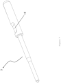
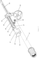
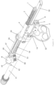
- Mechanism structure the subject matter of the invention, comprises a mechanism blog carrying out the firing process. Exploded view of said mechanism group can be seen in Figure 1 . Further, said mechanism structure comprises a particular barrel group so as to properly carry out the firing process. Exploded view of said barrel group can be seen Figure 16 .
- Trigger mechanism, cock structure, magazine structure, etc. other members that needs to exist in firearm structures, in which mechanism structure subject to the invention exists, may be standard structures.
- Mechanism group existing in the central position of mechanism structure subject to the invention is positioned such that it exactly coincides with the back portion of the barrel (61) structure.
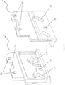
- Mechanism group is comprised of a mechanism head (14) in the center, and mechanism right cover (8) and mechanism left cover (6) that are positioned at the two opposing sides of the mechanism head (14) and are in a symmetrical form according to each other.
- Mechanism right cover (8) and mechanism left cover (6) helps mechanism head (14) with the movements to be carried out.
- Mechanism right cover (8) and mechanism left cover (6) are positioned such that they are opposing to sides of mechanism head (14).
- Positioned covers are mounted to each other by means of each cover pin housing (19) that exists at lower portions and faces each other.
- One cover mounting pin (16) mounts said cover structures to each other by means of inserting each end into a cover pin housing (19). As can be seen in Figure 12 , there is an oval space formed at lower surface of mechanism head (14) so that mechanism head (14) does not prevent cover mounting pin (16) from getting mounted. Cover mounting pin (16) can be connected to both cover structures without making a contact with the mechanism head (14) by means of said space.
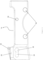
- Mechanism mounting pins (15) are positioned into two head pin housings (34) located on the side surfaces such that they are close to lower edge of the body of mechanism head (14). End portions of mechanism mounting pins (15) positioned in head pin housings (34) remain outside of the mechanism head (14). Ends of mechanism mounting pins (15) remaining outside enter into movement holes (17) that are symmetrical on the mechanism right cover (8) and mechanism left cover (6) and exist in twos on each cover.
- Said movement holes (17), as also can be seen in Figure 8 are in a longitudinal space form. This enables ends of mechanism mounting pins (15) to move in and out in the movement holes (17). However, the direction in which the movement holes (17) expand is not parallel to horizontal or perpendicular plane. Said direction comprises a slope such that it constitutes approximately 35 degree angle according to ground plane.
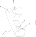
- Firing pin (5) structure to which cock structure strikes to start the firing, are positioned in the firing pin housing (30) on the back surface of mechanism head (14), in case the firearm structure in which the mechanism structure subject to the invention is triggered so as to be fired. Said firing pin (5) enters through firing pin housing (30) on the back surface of mechanism head (14), however end portion of firing pin (5) may stick out of firing pin cavity (27) on the front surface of the mechanism head (14). End portion of firing pin (5) that may stick out of firing pin cavity (27) is thinner than its remaining section.
- a firing pin spring (13) is located in the section in which the thinner end of firing pin (5) structure positioned in the mechanism head (14) exists. Firstly, the firing pin spring (13), then the firing pin (5) enters in firing pin housing (30). Objective of said firing pin spring (13) is to enable the firing pin (5) moving forward so as to carry out the firing process to take back its old position. There is a tether pin housing (35) at the point close to upper edge of the side surface of mechanism head (14). After the firing pin (5) is positioned in the firing pin housing (30), a tether pin for firing pin located in the tether pin housing (35) and firing pin (5) structure are fixed into the mechanism body (14).
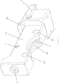
- a recoil spring tube (4) is placed exactly on the mechanism head (6) such that it coincides with between upper edges of mechanism right cover (8) and mechanism left cover (6).
- said recoil spring tube (4) is fastened between mechanism right cover (8) and mechanism left cover (6).
- the covers are seated on the symmetrical protrusion structures being on side surfaces of recoil spring tube (4) so as to ensure fastening process.
- small tube protrusions (37) on the side surfaces of recoil spring tube (4) such that they are on two sides of wide tube protrusions (38). While wide tube protrusions (38) are seated in wide tube housings (21), small tube protrusions (37) are seated in small tube housings (20) in twos on the cover structures. Small tube housings (20) are positioned such that they are at both edges of wide tube housings (21) on the upper section of cover structures. Therefore, while seating wide tube protrusions (38) in wide tube housings (21), small tube protrusions (37) are synchronously seated properly in the small tube housings (20). Thus, mechanism right cover (8) and mechanism left cover (6) are mounted very firmly to recoil spring tube (4).
- rod housing (39) in the form of cylindrical space expanding inward at the end portion facing to opposed side of barrel (61) of the recoil spring tube (4).
- rod housing (39) There is another space structure with smaller diameter at the end facing to barrel (61) of the recoil spring tube (4).
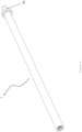
- Guide rod (1) that can be seen in Figure 4 is positioned in rod housing (39).
- recoil spring (2) Before positioning guide rod (1) in the rod housing (39), recoil spring (2) is seated on the end portion to be inserted in the guide rod (39).
- a spring plate (3) is attached to the same end of guide rod (1) after positioned on the guide rod (1) in order for recoil spring (2) to stay on the guide rod (1).
- spring plate (3) can move on the guide rod (1).
- Spring stopper (46) in the form of a protrusion that is positioned at the point close to the end with no spring plate (3) exists in the middle section of guide rod (1).
- Spring stopper (46) is a structure that prevents recoil spring (2) from moving backward on the guide rod (1) and helps recoil spring (2) with staying on the guide rod (1).
- Guide rod (1) together with the recoil spring (2) thereon, is positioned in rod housing (39) at the back section of recoil spring tube (4) such that it is the end with spring plate (3).
- Diameter of the space at frond side of recoil spring tube (4) is smaller than diameter of spring plate (3). Therefore, the spring plate (3) positioned in recoil spring tube (4) at the end of guide rode (1) cannot stick out of the end at the front side of recoil spring tube (4).
- Main objective of the guide rod (1) is to guide the recoil spring (2) ejecting empty cartridge in the chamber and loading a new cartridge in the barrel (61) in the course of firing, and enabling to take back its location in the normal position by pushing the mechanism sliding backward so as to cock firearm from back side of the firearm towards front side in which the barrel (61) takes place.
- Extractor housing (33) There is respectively one extractor housing (33), which is positioned symmetrically according to each other in both sides, at the front side in wide end portion of mechanism head (14) .
- Extractor housings (33) are inward space structures on the side surfaces of mechanism head (14).
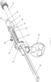
- Extractor (9) structure that can be seen in Figure 9 is positioned in one of the extractor housings (33).
- the extractor housing (33), in which the extractor is to be positioned, is determined according to the direction which firearm structure ejects the empty case. Therefore, its position can be varied preferably.
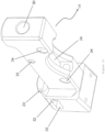
- Extractor (9) structure as can be seen in Figure 10 , comprises an extractor pin housing (49) in the form of space at its middle section. Process of positioning the extractor (9) in extractor housing (33) is carried out by means of extractor pin housing (49). Extractor (9) structure, which is positioned in extractor housing (33) such that extractor pin housing (49) stays inside, are fastened by means of extractor pin (12) positioned in extractor cavities (22) on the upper side of mechanism head (14). Extractor cavities (22) are structures in the form of two cylindrical spaces that are positioned symmetrically according to each other on the upper side of mechanism head (14). Said extractor pin (12) goes through extractor pin housing (49) by keep proceeding after entering in extractor cavity (22). Therefore, extractor (9) structure can be positioned in extractor housing (49) by means of extractor pin (12).
- Extractor (9) structure There is a spring protrusion (48) facilitating the extractor (9) to move at the back end, which is in a opposite direction of barrel, of extractor (9) structure positioned in extractor housing (33) by means of extractor pin (12).
- Spring protrusion (48) coincides exactly with the extractor spring cavity (32) when extractor (9) structure is positioned in extractor housing (33). Extractor spring cavity (32) is on the back end of extractor housing (33). Extractor spring (10) is positioned in extractor spring cavity (32). Thus, extractor spring (10) remains between extractor spring cavity (32) and spring protrusion (48).
- Extractor (9) structure may conduct circular movements depending on jamming and expanding movements of extractor spring (10) such that it takes the extractor pin (12) as the center.
- Extractor (9) structure is at the end on front side of mechanism head (14). Since the location in which mechanism head (14) exists is the very back portion of barrel (61) structure, the extractor (9) structure stays exactly behind the barrel (61) structure. Even end portion of extractor (9) structure facing towards the barrel (61) makes a contact with the cartridge structure positioned in the barrel (61) so as to be fired.
- Cartridge holding protrusion (45) is a structure that is designed so as to grip the base edge which exists in the base of cartridge in barrel and protrudes outward.
- cartridge holding protrusion (45) grips the protrusion at the cartridge base, said protrusion at the cartridge base is seated exactly on the cartridge base space (47).
- cartridge holding protrusion (45) can grip ideally the cartridge base.
- Main objective of the extractor (9) is to move the empty cartridge case that remains in the barrel backward by means of mechanism after firing processes is conducted. It is possible to move the empty cartridge case by means of cartridge holding protrusion (45) and cartridge base space (47). Extractor (9) enables the empty case to strike to ejector by moving the empty cartridge case backward and to eject it out of firearm structure.
- Mechanism rail (50) that is the backmost component of barrel group, as can be seen in Figure 27 , is positioned between said two structures such that it coincides immediately with upper side of the mechanism head (14) and immediately with underneath of recoil spring tube (4).
- Space form that lock housing (51) comprises is in a form and structure that exactly fits in lock protrusion (23).
- Main objective of the mechanism rail (50) is to lock mechanism head (14) for the purpose of pushing the bullet shot from cartridge by the effect of firing pressure in the course of firing.
- Mechanism head (14) enables to shoot the bullet through barrel (61) by pushing it by means of gas pressure arisen from the explosion of the cartridge in the barrel by fastening to barrel (61).
- Mechanism head (14) moves downward and forward traversely during its movement towards the barrel (61) thanks to its design, wherein it is locked to barrel (61) by moving upward and backward in the axis of movement holes (17) after its movement towards barrel (61) is finished.
- Mechanism head (14) prevents powder gas pushing bullet or shots from leaking by delaying first movement of mechanism pushed back after cartridge is fired until bullet or shots leave the barrel (61).
- firstly lock protrusion (23) on the mechanism head (14) leaves from the lock housing (51) on lower surface of mechanism rail (50) therein.
- mechanism head (14) moves downward. It moves backward as a whole with the components in mechanism head (14) after mechanism head (14) and mechanism rail (50) separate from each other.
- Mechanism head (14) enables to position both lock and cartridge in barrel (61) by way of pushing them.
- magazine disc (52) at the front end facing to barrel (61) of mechanism rail (50). Back end of the barrel (61) exists in the magazine disc (52).
- upper portion of the magazine disc (52) comprises a structure that can be mounted to mechanism rail (50). This allows said two structures to stay in a stabile position according to each other. Therefore, Types of montage between said structures may preferably in the form of various structures, different protrusion forms and space forms according to those.
- barrel crown (53) structure immediately in the front portion of mechanism rail (50) and magazine disc (52) in a mounted to each other form.
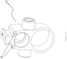
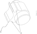
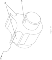
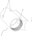
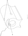
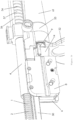
- the barrel crown (53) that can be seen in Figure 20 is in a very important and critical point. Basically, it is a structure that has two circular spaces positioned upside-down. Back end of the barrel (61) goes through the lower space of the barrel crown (53) before entering in magazine disc (52). Its upper space serves as a juncture of recoil spring tube (4) and push tube (57). Its main objective is to move synchronously the barrel (61) structure at its lower portion and the push tube (57)-recoil spring tube (4) that move based on gas at its upper portion.
- Push tube (57) is positioned on the barrel (61) structure such that it coincides with immediate front portion of recoil spring tube (4). Back end of the push tube (57) stays in the barrel crown (53). Push tube (57) moves mechanism head (14) backward by pushing the movement obtained from gas piston (42) in the gas chamber (41) at its front side to recoil spring tube (4) in the course of firing. In case of a normal position without firing, while recoil spring tube (4) and push tube (57) do not make a contact with each other, the movement arisen by means of gas pressure in the course of firing opens the lock and feeds the firearm by contacting subsequently these three component to each other.
- Push spring (54) is positioned on the push tube (57) such that it is at the back portion thereof.
- a cocking handle segment (55) is attached in front of push spring (54).
- Cocking handle segment (55) restricts movements of the push spring (54) and prevents push tube (57) from releasing from its front end. Since back end of the push spring (54) enters in the barrel crowns (53) along with the push tube (57), push spring (54) is squeezed between cocking handle segment (55) and recoil spring tube.
- Main objective of the push spring (54) is to enable the push tube (57) moving from front side towards back side to take its first position by means of the effect of movement obtained from gas piston or cocking handle (58).
- cocking handle segment (55) has a smaller diameter than the cocking handle protrusion (25) in the protruding form on the push tube (57), it is not possible to go over the cocking handle protrusion (25).
- cocking handle housing (26) on side surface of the section in which cocking handle protrusion (25) exists.
- Cocking handle housing (26) is the structure in which cocking handle (58) is positioned.
- Cocking handle segment (55) fastens cocking handle (58) into cocking handle housing (26) by means of pushing the cocking handle segment (5) at the front side of push spring (54).
- Cocking handle (58) basically enables to cock the firearm by drawing mechanism backward by a user, to load cartridge in the barrel and make it ready to fire. It has an ergonomic design which user can easily move with his/her finger. It can be attached to right side or left side according to user's preference thanks to symmetrical design of the cocking handle housing (26).
- a tube lid (60) is attached to front end of the push tube (57) structure.
- Said tube lid (60) has a structure in the cylindrical form.
- An end of tube lid (60) has a structure that can enter in front end of the push tube (57) structure.
- pin cavities (29) which are positioned on the two opposed edge and are in a uniform space form comprising a structure in which push tube pin (59) can enter, on the end of tube lid (60) that can enter in push tube (57).
- push tube holes (31) on the two edges that coincide with upper side of pin cavities (29) of the push tube (57).
- Push tube holes (31) exist exactly on the pin cavities (29) and tube lid (60) and push tube (57) are firmly mounted to each other by means of one push tube pin (59) that is positioned in said cavity structures.
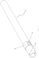
- push rail spaces (36) which are in a symmetrical structure according to each other, at both sides of upper section of the tube lid (60) that is positioned at the front end of push tube (57).
- Said push rail spaces (36) are the space structures in which push rail (56) that can be seen in Figure 16 can be positioned from both sides therein.
- Push rail (56) is comprised of two, thin and uniform tube structures which are positioned immediately on the push tube (57) structure, are in a parallel position to the push tube (57) and are in parallel location to each other.
- Push rail (56) structure is positioned such that it goes through push rail spaces (36) on the tube lid (60).
- push rail (56) structure is in a stabilized position.
- Main objective of the push rail (56) is to move push tube (57) in a parallel direction to the barrel (61) axis. It appoints the movement axis of push tube (57).
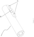
- gas chamber (41) immediately in front of free end of facing to barrel (61) muzzle of the tube lid (60) that is positioned in the front portion of push tube (57).
- Gas chamber (41) is positioned on the barrel (61) structure.
- gas piston (42) exactly in the middle of gas chamber (41).
- Gas piston (42) is the leading one of structures initiating the movements which the mechanism carries out with the effect of gas pressure arisen from firing.
- Gas piston (42) both exists in gas chamber (41) and is positioned such that its back end is exactly in front of tube lid (60). Therefore, it allows tube lid (60) to move push tube (57) backward by striking to tube lid (60) in the moment in which it moves backward with the effect of gas pressure.
- Recoil spring tube (4) enables firing circle to be completed by means of transmitting the movement obtained from push tube (57) to the mechanism.
- recoil spring (2) allows the mechanism sliding backwards by the drive obtained from the push tube (57) to move back towards barrel (61) and be locked.
- gas hole (40) in the area taking place on the barrel (61) in the interior surface of gas chamber (41). Said gas hole (40) transmits the gas in barrel (61) to the gas chamber (41).
- discharge holes (44) positioned to be at least one on the upper surface of gas chamber (41) which does not make a contact with the barrel (61) and faces outwards. Main objective of the discharge holes (44) is to discharge the excessive gas and to enable gas residues/particles entered in gas chamber (41) to be discharged in case there is too much burnt powder gas filled in the gas chamber (41). Thus, it is ensured that gas chamber (41) gets dirty later than the usual, and to increase the firing number that requires cleaning.
- gas chamber lid (43) at the end portion of gas chamber (41) facing towards end of the barrel (61). Gas chamber lid (43) keeps gas chamber (41) closed. It is fastened by means of lid pin (62).
Landscapes
- Engineering & Computer Science (AREA)
- General Engineering & Computer Science (AREA)
- Toys (AREA)
- Telescopes (AREA)
- Aiming, Guidance, Guns With A Light Source, Armor, Camouflage, And Targets (AREA)
Claims (1)
- Eine Mechanismusstruktur, die Folgendes umfasst:einen Schlagbolzen (5),einen Extraktor (9),ein Fass (61),ein Schubrohr (57),ein Rückholfederrohr (4),eine Magazinscheibe (52),ein Spanngriffsegment (55),einen Gaskolben (42),eine Gaskammer (41),ein Haltestiftgehäuse (35),eine Federhauskrone (53),einen Mechanismuskopf (14), der an der Rückseite der Laufstruktur (61) positioniert ist und das Abfeuern der Mechanismusstruktur ermöglicht,worinder Mechanismuskopf (14) auf seiner dem Lauf (61) gegenüberliegenden Rückseite ein Schlagbolzengehäuse (30) aufweist, in dem der Schlagbolzen (5) positioniert werden kann,wobei das Haltestiftgehäuse (35) das Schlagbolzengehäuse (30) von beiden Seitenflächen des Mechanismuskopfes (14) durchquert und das Haltestiftgehäuse einen Haltestift für den Schlagbolzen (11) aufnimmt,Extraktorgehäuse (33), die gegenüber Seitenflächen des vorderen Abschnitts des Mechanismuskopfs (14) positioniert sind,einen Verriegelungsvorsprung (23) in dreieckiger Form auf der Oberseite des vorderen Abschnitts des Mechanismuskopfs (14),wobei der Schlagbolzen (5) das Abfeuern einer schussbereiten Patrone im Mechanismus ermöglicht, wobei der Schlagbolzen (5) ein Haltegurtlager (18) umfasst, das als Aussparung geformt ist, in der der Haltegurtstift (11) positioniert werden kann, der Schlagbolzen (5) im Schlagbolzengehäuse (30) so positioniert ist, dass er aus einem Schlagbolzenhohlraum (27) an der Vorderfläche des Mechanismuskopfs (14) herausragt, und der Extraktor (9) in einem der Extraktorgehäuse (33) positioniert ist,der Extraktor (9) einen Patronenhaltevorsprung (45) aufweist, um eine Patronenbasis am vorderen Abschnitt des Mechanismuskopfes (14) zu halten, der Extraktor (9) einen Patronenbasisraum (47) unmittelbar hinter dem Patronenhaltevorsprung (45) umfasst, der als Aussparung geformt und so positioniert ist, dass er die Basis der Patronenstruktur richtig greift wobei die Laufkrone (53) zwei übereinanderliegende kreisförmige Räume aufweist,wobei der Lauf (61) durch den unteren Raum der Laufkrone (53) geht, bevor er in die Magazinscheibe (52) eintritt,wobei das Federrohr (4) und das Schubrohr (57) im oberen Raum zusammenlaufen, das Schubrohr (57) so angeordnet ist, dass es die vom Gaskolben (42) in der Gaskammer (41) erhaltene Bewegung auf das Rückholfederrohr (4) überträgt und dadurch bewirkt, dass der Mechanismuskopf (14) nach hinten gleitet,die Gaskammer (41) auf der Struktur des Zylinders (61) genau vor dem Tubendeckel (60) positioniert ist,die Gaskammer (41) ein Gasloch (40) aufweist, durch das das bei der Pulververbrennung entstehende Gas aufgenommen wird die Gaskammer (41) umfasst den Gaskolben (42), der aufgrund der Füllung der Gaskammer mit Gas die Bewegungen auslöst, die der Mechanismus ausführt die Gaskammer (41) Ablasslöcher (44) aufweist, um überschüssiges Gas und darin befindliche Pulverreste/Partikel abzuleiten,worinam Schubrohr (57) ist eine Schubfeder (54) vorgesehen, Das Spanngriffsegment (55) ist vor der Druckfeder (54) angebracht, um Bewegungen der Druckfeder (54) einzuschränken und dadurch zu verhindern, dass sich das Druckrohr (57) von seinem vorderen Ende der Druckfeder (54) löst,das Schubrohr (57) einen Spanngriffvorsprung (25) umfasst, wobei das Spanngriffsegment (55) einen kleineren Durchmesser als der Spanngriffvorsprung (25) aufweist, so dass es nicht über den Spanngriffvorsprung (25) hinausgehen kann das Schubrohr (57) ein Spanngriffgehäuse (26) an den Seitenflächen des Spanngriffvorsprungs (25) umfasst, in dem ein Spanngriff (58) positioniert ist,wobei der Rohrdeckel (60) ein Ende aufweist, das in das vordere Ende des Schubrohrs (57) eingeführt werden kann, Der Tubendeckel (60) ist an dem Schubrohr (57) mittels eines Schubrohrstifts (59) befestigt, der im Stifthohlraum (29) am Ende des Schubrohrs (57) positioniert ist, und der Tubendeckel (60) angeordnet,um die von der Gaskammer (41) übertragene Bewegung auf das Schubrohr (57) zu übertragen.
Applications Claiming Priority (2)
| Application Number | Priority Date | Filing Date | Title |
|---|---|---|---|
| TR2017/15303A TR201715303A2 (tr) | 2017-10-10 | 2017-10-10 | Tüfekler İçin Yeni Bir Mekanizma Yapısı |
| PCT/TR2018/050368 WO2019190418A2 (en) | 2017-10-10 | 2018-07-13 | A new mechanism structure for firearms |
Publications (3)
| Publication Number | Publication Date |
|---|---|
| EP3704435A2 EP3704435A2 (de) | 2020-09-09 |
| EP3704435A4 EP3704435A4 (de) | 2022-06-15 |
| EP3704435B1 true EP3704435B1 (de) | 2024-04-17 |
Family
ID=67980387
Family Applications (1)
| Application Number | Title | Priority Date | Filing Date |
|---|---|---|---|
| EP18912100.7A Active EP3704435B1 (de) | 2017-10-10 | 2018-07-13 | Neue mechanismusstruktur für schusswaffen |
Country Status (5)
| Country | Link |
|---|---|
| US (1) | US11175111B2 (de) |
| EP (1) | EP3704435B1 (de) |
| IL (1) | IL273342A (de) |
| TR (1) | TR201715303A2 (de) |
| WO (1) | WO2019190418A2 (de) |
Family Cites Families (17)
| Publication number | Priority date | Publication date | Assignee | Title |
|---|---|---|---|---|
| US1572450A (en) * | 1919-05-15 | 1926-02-09 | Marlin Firearms Corp | Automatic rifle |
| FR555255A (fr) * | 1922-02-27 | 1923-06-27 | Carabine mitraillette automatique de chasse | |
| CH206755A (fr) * | 1937-09-27 | 1939-08-31 | Anonima Nazionale Cogne Soc | Mécanisme de fermeture pour armes à feu. |
| US2554618A (en) * | 1946-12-16 | 1951-05-29 | Paul H Dixon | Gas piston for operating automatic gun breech locks |
| US2601808A (en) * | 1948-09-15 | 1952-07-01 | Howard R Clarke | Breech bolt lock and actuator for firearms |
| BE515573A (de) * | 1951-11-17 | |||
| CH313589A (fr) * | 1953-02-02 | 1956-04-30 | Kara Haim | Arme à feu portative |
| US2960917A (en) * | 1959-01-22 | 1960-11-22 | Albert J Lizza | Lock means for telescopic firearm bolts |
| US3405471A (en) * | 1966-05-24 | 1968-10-15 | Zd Y Jana Svermy Narodni Podni | Firearm having disconnectable sections |
| DE19734042C2 (de) * | 1997-08-06 | 1999-10-28 | Sommer & Ockenfuss Gmbh | Blockverschluß für Rohrwaffen |
| DE10240891A1 (de) * | 2002-09-04 | 2004-03-18 | Heckler & Koch Gmbh | Handfeuerwaffe mit verriegeltem Verschluß |
| DE102007052105B3 (de) | 2007-10-31 | 2009-05-28 | Heckler & Koch Gmbh | Fanghebel, Abzugseinrichtung und Griffstück für eine Waffe |
| US9400147B2 (en) * | 2010-05-06 | 2016-07-26 | Rock River Arms, Inc. | Firearm having gas piston system |
| US9032860B2 (en) * | 2012-12-17 | 2015-05-19 | Faxon Firearms, Llc | Gas piston operated upper receiver system |
| WO2016019297A1 (en) | 2014-08-01 | 2016-02-04 | Helvetic Design Corporation | Firearm system and methods of assembly and disassembly |
| US9644913B2 (en) | 2015-04-17 | 2017-05-09 | Cadequip, Inc. | Multi-stage trigger mechanism for rifle |
| US10215513B2 (en) * | 2015-12-18 | 2019-02-26 | Jeffrey Scott Cross | AR style receiver compatible with pistol magazines and cartridges |
-
2017
- 2017-10-10 TR TR2017/15303A patent/TR201715303A2/tr unknown
-
2018
- 2018-07-13 WO PCT/TR2018/050368 patent/WO2019190418A2/en not_active Ceased
- 2018-07-13 EP EP18912100.7A patent/EP3704435B1/de active Active
- 2018-07-13 US US16/642,645 patent/US11175111B2/en active Active
-
2020
- 2020-03-17 IL IL273342A patent/IL273342A/en unknown
Also Published As
| Publication number | Publication date |
|---|---|
| WO2019190418A3 (en) | 2019-12-05 |
| WO2019190418A2 (en) | 2019-10-03 |
| IL273342A (en) | 2020-05-31 |
| EP3704435A4 (de) | 2022-06-15 |
| EP3704435A2 (de) | 2020-09-09 |
| US20210156635A1 (en) | 2021-05-27 |
| TR201715303A2 (tr) | 2019-04-22 |
| US11175111B2 (en) | 2021-11-16 |
Similar Documents
| Publication | Publication Date | Title |
|---|---|---|
| US7201094B2 (en) | Firearm with enhanced recoil and control characteristics | |
| US8667722B2 (en) | Firearm with enhanced recoil and control characteristics | |
| US6971202B2 (en) | Gas operated action for auto-loading firearms | |
| US8726554B2 (en) | Magazine well adapter and kit | |
| US8813405B2 (en) | Firearm with enhanced recoil and control characteristics | |
| US5900577A (en) | Modular, multi-caliber weapon system | |
| US8176668B2 (en) | Recoil reducer for use with a firearm | |
| US7631453B2 (en) | Interchangeable caliber semi-automatic rifle | |
| US20100077643A1 (en) | Firearm with enhanced recoil and control characteristics | |
| US20170321978A1 (en) | Tactical rifle | |
| US20210123699A1 (en) | Apparatus and method to reduce muzzle rise in a firearm | |
| EP3784975B1 (de) | Rückstossanordnung für ein gewehr | |
| US9038524B2 (en) | Firearm with enhanced recoil and control characters | |
| US20170146311A1 (en) | Pistol dry fire device | |
| EP3704435B1 (de) | Neue mechanismusstruktur für schusswaffen | |
| EP3704436B1 (de) | Dreisäulige magazinstruktur für schusswaffen | |
| TW482888B (en) | Conversion of firearms to fire reduced-energy ammunition | |
| US20160265859A1 (en) | Blowback-type firing unit | |
| RU2226251C2 (ru) | Полуавтоматическое стрелковое оружие (варианты) системы кобец | |
| RU2836424C1 (ru) | Пистолет с поперечно скользящим затвором с автоматическим взводом | |
| RU2284441C2 (ru) | Комбинированное ружье | |
| ES3006453T3 (en) | Upper receiver for modular shotgun | |
| RU2116602C1 (ru) | Стрелковое оружие револьвер сотскова | |
| RU207692U1 (ru) | Безоткатное многозарядное оружие без обратного скольжения с магазинным питанием | |
| RU2675309C2 (ru) | Самозарядный пистолет |
Legal Events
| Date | Code | Title | Description |
|---|---|---|---|
| STAA | Information on the status of an ep patent application or granted ep patent |
Free format text: STATUS: THE INTERNATIONAL PUBLICATION HAS BEEN MADE |
|
| PUAI | Public reference made under article 153(3) epc to a published international application that has entered the european phase |
Free format text: ORIGINAL CODE: 0009012 |
|
| STAA | Information on the status of an ep patent application or granted ep patent |
Free format text: STATUS: REQUEST FOR EXAMINATION WAS MADE |
|
| 17P | Request for examination filed |
Effective date: 20200219 |
|
| AK | Designated contracting states |
Kind code of ref document: A2 Designated state(s): AL AT BE BG CH CY CZ DE DK EE ES FI FR GB GR HR HU IE IS IT LI LT LU LV MC MK MT NL NO PL PT RO RS SE SI SK SM TR |
|
| AX | Request for extension of the european patent |
Extension state: BA ME |
|
| DAV | Request for validation of the european patent (deleted) | ||
| DAX | Request for extension of the european patent (deleted) | ||
| A4 | Supplementary search report drawn up and despatched |
Effective date: 20220512 |
|
| RIC1 | Information provided on ipc code assigned before grant |
Ipc: F41A 35/06 20060101ALI20220506BHEP Ipc: F41A 3/34 20060101ALI20220506BHEP Ipc: F41A 15/14 20060101ALI20220506BHEP Ipc: F41A 5/28 20060101ALI20220506BHEP Ipc: F41A 5/18 20060101ALI20220506BHEP Ipc: F41A 3/26 20060101AFI20220506BHEP |
|
| GRAP | Despatch of communication of intention to grant a patent |
Free format text: ORIGINAL CODE: EPIDOSNIGR1 |
|
| STAA | Information on the status of an ep patent application or granted ep patent |
Free format text: STATUS: GRANT OF PATENT IS INTENDED |
|
| INTG | Intention to grant announced |
Effective date: 20240131 |
|
| GRAS | Grant fee paid |
Free format text: ORIGINAL CODE: EPIDOSNIGR3 |
|
| GRAA | (expected) grant |
Free format text: ORIGINAL CODE: 0009210 |
|
| STAA | Information on the status of an ep patent application or granted ep patent |
Free format text: STATUS: THE PATENT HAS BEEN GRANTED |
|
| AK | Designated contracting states |
Kind code of ref document: B1 Designated state(s): AL AT BE BG CH CY CZ DE DK EE ES FI FR GB GR HR HU IE IS IT LI LT LU LV MC MK MT NL NO PL PT RO RS SE SI SK SM TR |
|
| REG | Reference to a national code |
Ref country code: GB Ref legal event code: FG4D |
|
| REG | Reference to a national code |
Ref country code: CH Ref legal event code: EP |
|
| REG | Reference to a national code |
Ref country code: DE Ref legal event code: R096 Ref document number: 602018068387 Country of ref document: DE |
|
| REG | Reference to a national code |
Ref country code: IE Ref legal event code: FG4D |
|
| REG | Reference to a national code |
Ref country code: LT Ref legal event code: MG9D |
|
| REG | Reference to a national code |
Ref country code: NL Ref legal event code: MP Effective date: 20240417 |
|
| REG | Reference to a national code |
Ref country code: AT Ref legal event code: MK05 Ref document number: 1677618 Country of ref document: AT Kind code of ref document: T Effective date: 20240417 |
|
| PG25 | Lapsed in a contracting state [announced via postgrant information from national office to epo] |
Ref country code: NL Free format text: LAPSE BECAUSE OF FAILURE TO SUBMIT A TRANSLATION OF THE DESCRIPTION OR TO PAY THE FEE WITHIN THE PRESCRIBED TIME-LIMIT Effective date: 20240417 |
|
| PG25 | Lapsed in a contracting state [announced via postgrant information from national office to epo] |
Ref country code: NL Free format text: LAPSE BECAUSE OF FAILURE TO SUBMIT A TRANSLATION OF THE DESCRIPTION OR TO PAY THE FEE WITHIN THE PRESCRIBED TIME-LIMIT Effective date: 20240417 |
|
| PG25 | Lapsed in a contracting state [announced via postgrant information from national office to epo] |
Ref country code: IS Free format text: LAPSE BECAUSE OF FAILURE TO SUBMIT A TRANSLATION OF THE DESCRIPTION OR TO PAY THE FEE WITHIN THE PRESCRIBED TIME-LIMIT Effective date: 20240817 |
|
| PG25 | Lapsed in a contracting state [announced via postgrant information from national office to epo] |
Ref country code: BG Free format text: LAPSE BECAUSE OF FAILURE TO SUBMIT A TRANSLATION OF THE DESCRIPTION OR TO PAY THE FEE WITHIN THE PRESCRIBED TIME-LIMIT Effective date: 20240417 |
|
| PG25 | Lapsed in a contracting state [announced via postgrant information from national office to epo] |
Ref country code: HR Free format text: LAPSE BECAUSE OF FAILURE TO SUBMIT A TRANSLATION OF THE DESCRIPTION OR TO PAY THE FEE WITHIN THE PRESCRIBED TIME-LIMIT Effective date: 20240417 Ref country code: FI Free format text: LAPSE BECAUSE OF FAILURE TO SUBMIT A TRANSLATION OF THE DESCRIPTION OR TO PAY THE FEE WITHIN THE PRESCRIBED TIME-LIMIT Effective date: 20240417 |
|
| PG25 | Lapsed in a contracting state [announced via postgrant information from national office to epo] |
Ref country code: GR Free format text: LAPSE BECAUSE OF FAILURE TO SUBMIT A TRANSLATION OF THE DESCRIPTION OR TO PAY THE FEE WITHIN THE PRESCRIBED TIME-LIMIT Effective date: 20240718 |
|
| PG25 | Lapsed in a contracting state [announced via postgrant information from national office to epo] |
Ref country code: PT Free format text: LAPSE BECAUSE OF FAILURE TO SUBMIT A TRANSLATION OF THE DESCRIPTION OR TO PAY THE FEE WITHIN THE PRESCRIBED TIME-LIMIT Effective date: 20240819 |
|
| PG25 | Lapsed in a contracting state [announced via postgrant information from national office to epo] |
Ref country code: ES Free format text: LAPSE BECAUSE OF FAILURE TO SUBMIT A TRANSLATION OF THE DESCRIPTION OR TO PAY THE FEE WITHIN THE PRESCRIBED TIME-LIMIT Effective date: 20240417 |
|
| PG25 | Lapsed in a contracting state [announced via postgrant information from national office to epo] |
Ref country code: AT Free format text: LAPSE BECAUSE OF FAILURE TO SUBMIT A TRANSLATION OF THE DESCRIPTION OR TO PAY THE FEE WITHIN THE PRESCRIBED TIME-LIMIT Effective date: 20240417 |
|
| PG25 | Lapsed in a contracting state [announced via postgrant information from national office to epo] |
Ref country code: PL Free format text: LAPSE BECAUSE OF FAILURE TO SUBMIT A TRANSLATION OF THE DESCRIPTION OR TO PAY THE FEE WITHIN THE PRESCRIBED TIME-LIMIT Effective date: 20240417 |
|
| PG25 | Lapsed in a contracting state [announced via postgrant information from national office to epo] |
Ref country code: LV Free format text: LAPSE BECAUSE OF FAILURE TO SUBMIT A TRANSLATION OF THE DESCRIPTION OR TO PAY THE FEE WITHIN THE PRESCRIBED TIME-LIMIT Effective date: 20240417 |
|
| PG25 | Lapsed in a contracting state [announced via postgrant information from national office to epo] |
Ref country code: PT Free format text: LAPSE BECAUSE OF FAILURE TO SUBMIT A TRANSLATION OF THE DESCRIPTION OR TO PAY THE FEE WITHIN THE PRESCRIBED TIME-LIMIT Effective date: 20240819 Ref country code: PL Free format text: LAPSE BECAUSE OF FAILURE TO SUBMIT A TRANSLATION OF THE DESCRIPTION OR TO PAY THE FEE WITHIN THE PRESCRIBED TIME-LIMIT Effective date: 20240417 Ref country code: NO Free format text: LAPSE BECAUSE OF FAILURE TO SUBMIT A TRANSLATION OF THE DESCRIPTION OR TO PAY THE FEE WITHIN THE PRESCRIBED TIME-LIMIT Effective date: 20240717 Ref country code: LV Free format text: LAPSE BECAUSE OF FAILURE TO SUBMIT A TRANSLATION OF THE DESCRIPTION OR TO PAY THE FEE WITHIN THE PRESCRIBED TIME-LIMIT Effective date: 20240417 Ref country code: IS Free format text: LAPSE BECAUSE OF FAILURE TO SUBMIT A TRANSLATION OF THE DESCRIPTION OR TO PAY THE FEE WITHIN THE PRESCRIBED TIME-LIMIT Effective date: 20240817 Ref country code: HR Free format text: LAPSE BECAUSE OF FAILURE TO SUBMIT A TRANSLATION OF THE DESCRIPTION OR TO PAY THE FEE WITHIN THE PRESCRIBED TIME-LIMIT Effective date: 20240417 Ref country code: GR Free format text: LAPSE BECAUSE OF FAILURE TO SUBMIT A TRANSLATION OF THE DESCRIPTION OR TO PAY THE FEE WITHIN THE PRESCRIBED TIME-LIMIT Effective date: 20240718 Ref country code: FI Free format text: LAPSE BECAUSE OF FAILURE TO SUBMIT A TRANSLATION OF THE DESCRIPTION OR TO PAY THE FEE WITHIN THE PRESCRIBED TIME-LIMIT Effective date: 20240417 Ref country code: ES Free format text: LAPSE BECAUSE OF FAILURE TO SUBMIT A TRANSLATION OF THE DESCRIPTION OR TO PAY THE FEE WITHIN THE PRESCRIBED TIME-LIMIT Effective date: 20240417 Ref country code: BG Free format text: LAPSE BECAUSE OF FAILURE TO SUBMIT A TRANSLATION OF THE DESCRIPTION OR TO PAY THE FEE WITHIN THE PRESCRIBED TIME-LIMIT Effective date: 20240417 Ref country code: AT Free format text: LAPSE BECAUSE OF FAILURE TO SUBMIT A TRANSLATION OF THE DESCRIPTION OR TO PAY THE FEE WITHIN THE PRESCRIBED TIME-LIMIT Effective date: 20240417 Ref country code: RS Free format text: LAPSE BECAUSE OF FAILURE TO SUBMIT A TRANSLATION OF THE DESCRIPTION OR TO PAY THE FEE WITHIN THE PRESCRIBED TIME-LIMIT Effective date: 20240717 |
|
| PG25 | Lapsed in a contracting state [announced via postgrant information from national office to epo] |
Ref country code: DK Free format text: LAPSE BECAUSE OF FAILURE TO SUBMIT A TRANSLATION OF THE DESCRIPTION OR TO PAY THE FEE WITHIN THE PRESCRIBED TIME-LIMIT Effective date: 20240417 |
|
| REG | Reference to a national code |
Ref country code: DE Ref legal event code: R097 Ref document number: 602018068387 Country of ref document: DE |
|
| PG25 | Lapsed in a contracting state [announced via postgrant information from national office to epo] |
Ref country code: EE Free format text: LAPSE BECAUSE OF FAILURE TO SUBMIT A TRANSLATION OF THE DESCRIPTION OR TO PAY THE FEE WITHIN THE PRESCRIBED TIME-LIMIT Effective date: 20240417 |
|
| PG25 | Lapsed in a contracting state [announced via postgrant information from national office to epo] |
Ref country code: CZ Free format text: LAPSE BECAUSE OF FAILURE TO SUBMIT A TRANSLATION OF THE DESCRIPTION OR TO PAY THE FEE WITHIN THE PRESCRIBED TIME-LIMIT Effective date: 20240417 |
|
| PG25 | Lapsed in a contracting state [announced via postgrant information from national office to epo] |
Ref country code: RO Free format text: LAPSE BECAUSE OF FAILURE TO SUBMIT A TRANSLATION OF THE DESCRIPTION OR TO PAY THE FEE WITHIN THE PRESCRIBED TIME-LIMIT Effective date: 20240417 Ref country code: SK Free format text: LAPSE BECAUSE OF FAILURE TO SUBMIT A TRANSLATION OF THE DESCRIPTION OR TO PAY THE FEE WITHIN THE PRESCRIBED TIME-LIMIT Effective date: 20240417 |
|
| PG25 | Lapsed in a contracting state [announced via postgrant information from national office to epo] |
Ref country code: SM Free format text: LAPSE BECAUSE OF FAILURE TO SUBMIT A TRANSLATION OF THE DESCRIPTION OR TO PAY THE FEE WITHIN THE PRESCRIBED TIME-LIMIT Effective date: 20240417 |
|
| PG25 | Lapsed in a contracting state [announced via postgrant information from national office to epo] |
Ref country code: SM Free format text: LAPSE BECAUSE OF FAILURE TO SUBMIT A TRANSLATION OF THE DESCRIPTION OR TO PAY THE FEE WITHIN THE PRESCRIBED TIME-LIMIT Effective date: 20240417 Ref country code: SK Free format text: LAPSE BECAUSE OF FAILURE TO SUBMIT A TRANSLATION OF THE DESCRIPTION OR TO PAY THE FEE WITHIN THE PRESCRIBED TIME-LIMIT Effective date: 20240417 Ref country code: RO Free format text: LAPSE BECAUSE OF FAILURE TO SUBMIT A TRANSLATION OF THE DESCRIPTION OR TO PAY THE FEE WITHIN THE PRESCRIBED TIME-LIMIT Effective date: 20240417 Ref country code: EE Free format text: LAPSE BECAUSE OF FAILURE TO SUBMIT A TRANSLATION OF THE DESCRIPTION OR TO PAY THE FEE WITHIN THE PRESCRIBED TIME-LIMIT Effective date: 20240417 Ref country code: DK Free format text: LAPSE BECAUSE OF FAILURE TO SUBMIT A TRANSLATION OF THE DESCRIPTION OR TO PAY THE FEE WITHIN THE PRESCRIBED TIME-LIMIT Effective date: 20240417 Ref country code: CZ Free format text: LAPSE BECAUSE OF FAILURE TO SUBMIT A TRANSLATION OF THE DESCRIPTION OR TO PAY THE FEE WITHIN THE PRESCRIBED TIME-LIMIT Effective date: 20240417 |
|
| REG | Reference to a national code |
Ref country code: DE Ref legal event code: R119 Ref document number: 602018068387 Country of ref document: DE |
|
| PG25 | Lapsed in a contracting state [announced via postgrant information from national office to epo] |
Ref country code: IT Free format text: LAPSE BECAUSE OF FAILURE TO SUBMIT A TRANSLATION OF THE DESCRIPTION OR TO PAY THE FEE WITHIN THE PRESCRIBED TIME-LIMIT Effective date: 20240417 Ref country code: MC Free format text: LAPSE BECAUSE OF FAILURE TO SUBMIT A TRANSLATION OF THE DESCRIPTION OR TO PAY THE FEE WITHIN THE PRESCRIBED TIME-LIMIT Effective date: 20240417 |
|
| PLBE | No opposition filed within time limit |
Free format text: ORIGINAL CODE: 0009261 |
|
| STAA | Information on the status of an ep patent application or granted ep patent |
Free format text: STATUS: NO OPPOSITION FILED WITHIN TIME LIMIT |
|
| REG | Reference to a national code |
Ref country code: CH Ref legal event code: PL |
|
| PG25 | Lapsed in a contracting state [announced via postgrant information from national office to epo] |
Ref country code: LU Free format text: LAPSE BECAUSE OF NON-PAYMENT OF DUE FEES Effective date: 20240713 |
|
| 26N | No opposition filed |
Effective date: 20250120 |
|
| GBPC | Gb: european patent ceased through non-payment of renewal fee |
Effective date: 20240717 |
|
| PG25 | Lapsed in a contracting state [announced via postgrant information from national office to epo] |
Ref country code: LU Free format text: LAPSE BECAUSE OF NON-PAYMENT OF DUE FEES Effective date: 20240713 |
|
| PG25 | Lapsed in a contracting state [announced via postgrant information from national office to epo] |
Ref country code: DE Free format text: LAPSE BECAUSE OF NON-PAYMENT OF DUE FEES Effective date: 20250201 |
|
| PG25 | Lapsed in a contracting state [announced via postgrant information from national office to epo] |
Ref country code: CH Free format text: LAPSE BECAUSE OF NON-PAYMENT OF DUE FEES Effective date: 20240731 Ref country code: SI Free format text: LAPSE BECAUSE OF FAILURE TO SUBMIT A TRANSLATION OF THE DESCRIPTION OR TO PAY THE FEE WITHIN THE PRESCRIBED TIME-LIMIT Effective date: 20240417 Ref country code: BE Free format text: LAPSE BECAUSE OF NON-PAYMENT OF DUE FEES Effective date: 20240731 |
|
| PG25 | Lapsed in a contracting state [announced via postgrant information from national office to epo] |
Ref country code: FR Free format text: LAPSE BECAUSE OF NON-PAYMENT OF DUE FEES Effective date: 20240731 |
|
| PG25 | Lapsed in a contracting state [announced via postgrant information from national office to epo] |
Ref country code: GB Free format text: LAPSE BECAUSE OF NON-PAYMENT OF DUE FEES Effective date: 20240717 |
|
| REG | Reference to a national code |
Ref country code: BE Ref legal event code: MM Effective date: 20240731 |
|
| PG25 | Lapsed in a contracting state [announced via postgrant information from national office to epo] |
Ref country code: IE Free format text: LAPSE BECAUSE OF NON-PAYMENT OF DUE FEES Effective date: 20240713 |
|
| PG25 | Lapsed in a contracting state [announced via postgrant information from national office to epo] |
Ref country code: SE Free format text: LAPSE BECAUSE OF FAILURE TO SUBMIT A TRANSLATION OF THE DESCRIPTION OR TO PAY THE FEE WITHIN THE PRESCRIBED TIME-LIMIT Effective date: 20240417 |
|
| PG25 | Lapsed in a contracting state [announced via postgrant information from national office to epo] |
Ref country code: CY Free format text: LAPSE BECAUSE OF FAILURE TO SUBMIT A TRANSLATION OF THE DESCRIPTION OR TO PAY THE FEE WITHIN THE PRESCRIBED TIME-LIMIT; INVALID AB INITIO Effective date: 20180713 |