EP3703988B1 - Redundant integrated parking brake release circuit - Google Patents
Redundant integrated parking brake release circuit Download PDFInfo
- Publication number
- EP3703988B1 EP3703988B1 EP18807183.1A EP18807183A EP3703988B1 EP 3703988 B1 EP3703988 B1 EP 3703988B1 EP 18807183 A EP18807183 A EP 18807183A EP 3703988 B1 EP3703988 B1 EP 3703988B1
- Authority
- EP
- European Patent Office
- Prior art keywords
- parking brake
- electric motor
- electrical energy
- processor
- normally
- Prior art date
- Legal status (The legal status is an assumption and is not a legal conclusion. Google has not performed a legal analysis and makes no representation as to the accuracy of the status listed.)
- Active
Links
- 238000000034 method Methods 0.000 claims description 8
- 230000002441 reversible effect Effects 0.000 description 3
- 230000005669 field effect Effects 0.000 description 2
- 230000005856 abnormality Effects 0.000 description 1
- 230000004913 activation Effects 0.000 description 1
- 230000000994 depressogenic effect Effects 0.000 description 1
- 238000010586 diagram Methods 0.000 description 1
Images
Classifications
-
- B—PERFORMING OPERATIONS; TRANSPORTING
- B60—VEHICLES IN GENERAL
- B60T—VEHICLE BRAKE CONTROL SYSTEMS OR PARTS THEREOF; BRAKE CONTROL SYSTEMS OR PARTS THEREOF, IN GENERAL; ARRANGEMENT OF BRAKING ELEMENTS ON VEHICLES IN GENERAL; PORTABLE DEVICES FOR PREVENTING UNWANTED MOVEMENT OF VEHICLES; VEHICLE MODIFICATIONS TO FACILITATE COOLING OF BRAKES
- B60T13/00—Transmitting braking action from initiating means to ultimate brake actuator with power assistance or drive; Brake systems incorporating such transmitting means, e.g. air-pressure brake systems
- B60T13/74—Transmitting braking action from initiating means to ultimate brake actuator with power assistance or drive; Brake systems incorporating such transmitting means, e.g. air-pressure brake systems with electrical assistance or drive
- B60T13/746—Transmitting braking action from initiating means to ultimate brake actuator with power assistance or drive; Brake systems incorporating such transmitting means, e.g. air-pressure brake systems with electrical assistance or drive and mechanical transmission of the braking action
-
- B—PERFORMING OPERATIONS; TRANSPORTING
- B60—VEHICLES IN GENERAL
- B60T—VEHICLE BRAKE CONTROL SYSTEMS OR PARTS THEREOF; BRAKE CONTROL SYSTEMS OR PARTS THEREOF, IN GENERAL; ARRANGEMENT OF BRAKING ELEMENTS ON VEHICLES IN GENERAL; PORTABLE DEVICES FOR PREVENTING UNWANTED MOVEMENT OF VEHICLES; VEHICLE MODIFICATIONS TO FACILITATE COOLING OF BRAKES
- B60T7/00—Brake-action initiating means
- B60T7/02—Brake-action initiating means for personal initiation
- B60T7/04—Brake-action initiating means for personal initiation foot actuated
- B60T7/045—Brake-action initiating means for personal initiation foot actuated with locking and release means, e.g. providing parking brake application
-
- B—PERFORMING OPERATIONS; TRANSPORTING
- B60—VEHICLES IN GENERAL
- B60T—VEHICLE BRAKE CONTROL SYSTEMS OR PARTS THEREOF; BRAKE CONTROL SYSTEMS OR PARTS THEREOF, IN GENERAL; ARRANGEMENT OF BRAKING ELEMENTS ON VEHICLES IN GENERAL; PORTABLE DEVICES FOR PREVENTING UNWANTED MOVEMENT OF VEHICLES; VEHICLE MODIFICATIONS TO FACILITATE COOLING OF BRAKES
- B60T13/00—Transmitting braking action from initiating means to ultimate brake actuator with power assistance or drive; Brake systems incorporating such transmitting means, e.g. air-pressure brake systems
- B60T13/10—Transmitting braking action from initiating means to ultimate brake actuator with power assistance or drive; Brake systems incorporating such transmitting means, e.g. air-pressure brake systems with fluid assistance, drive, or release
- B60T13/66—Electrical control in fluid-pressure brake systems
- B60T13/662—Electrical control in fluid-pressure brake systems characterised by specified functions of the control system components
-
- B—PERFORMING OPERATIONS; TRANSPORTING
- B60—VEHICLES IN GENERAL
- B60T—VEHICLE BRAKE CONTROL SYSTEMS OR PARTS THEREOF; BRAKE CONTROL SYSTEMS OR PARTS THEREOF, IN GENERAL; ARRANGEMENT OF BRAKING ELEMENTS ON VEHICLES IN GENERAL; PORTABLE DEVICES FOR PREVENTING UNWANTED MOVEMENT OF VEHICLES; VEHICLE MODIFICATIONS TO FACILITATE COOLING OF BRAKES
- B60T13/00—Transmitting braking action from initiating means to ultimate brake actuator with power assistance or drive; Brake systems incorporating such transmitting means, e.g. air-pressure brake systems
- B60T13/74—Transmitting braking action from initiating means to ultimate brake actuator with power assistance or drive; Brake systems incorporating such transmitting means, e.g. air-pressure brake systems with electrical assistance or drive
- B60T13/741—Transmitting braking action from initiating means to ultimate brake actuator with power assistance or drive; Brake systems incorporating such transmitting means, e.g. air-pressure brake systems with electrical assistance or drive acting on an ultimate actuator
- B60T13/743—Transmitting braking action from initiating means to ultimate brake actuator with power assistance or drive; Brake systems incorporating such transmitting means, e.g. air-pressure brake systems with electrical assistance or drive acting on an ultimate actuator with a spring accumulator
-
- B—PERFORMING OPERATIONS; TRANSPORTING
- B60—VEHICLES IN GENERAL
- B60T—VEHICLE BRAKE CONTROL SYSTEMS OR PARTS THEREOF; BRAKE CONTROL SYSTEMS OR PARTS THEREOF, IN GENERAL; ARRANGEMENT OF BRAKING ELEMENTS ON VEHICLES IN GENERAL; PORTABLE DEVICES FOR PREVENTING UNWANTED MOVEMENT OF VEHICLES; VEHICLE MODIFICATIONS TO FACILITATE COOLING OF BRAKES
- B60T17/00—Component parts, details, or accessories of power brake systems not covered by groups B60T8/00, B60T13/00 or B60T15/00, or presenting other characteristic features
- B60T17/18—Safety devices; Monitoring
- B60T17/22—Devices for monitoring or checking brake systems; Signal devices
- B60T17/221—Procedure or apparatus for checking or keeping in a correct functioning condition of brake systems
-
- B—PERFORMING OPERATIONS; TRANSPORTING
- B60—VEHICLES IN GENERAL
- B60T—VEHICLE BRAKE CONTROL SYSTEMS OR PARTS THEREOF; BRAKE CONTROL SYSTEMS OR PARTS THEREOF, IN GENERAL; ARRANGEMENT OF BRAKING ELEMENTS ON VEHICLES IN GENERAL; PORTABLE DEVICES FOR PREVENTING UNWANTED MOVEMENT OF VEHICLES; VEHICLE MODIFICATIONS TO FACILITATE COOLING OF BRAKES
- B60T7/00—Brake-action initiating means
- B60T7/02—Brake-action initiating means for personal initiation
- B60T7/08—Brake-action initiating means for personal initiation hand actuated
- B60T7/10—Disposition of hand control
- B60T7/102—Disposition of hand control by means of a tilting lever
- B60T7/104—Disposition of hand control by means of a tilting lever with a locking mechanism
- B60T7/105—Disposition of hand control by means of a tilting lever with a locking mechanism the lock being released by means of a push button
-
- B—PERFORMING OPERATIONS; TRANSPORTING
- B60—VEHICLES IN GENERAL
- B60T—VEHICLE BRAKE CONTROL SYSTEMS OR PARTS THEREOF; BRAKE CONTROL SYSTEMS OR PARTS THEREOF, IN GENERAL; ARRANGEMENT OF BRAKING ELEMENTS ON VEHICLES IN GENERAL; PORTABLE DEVICES FOR PREVENTING UNWANTED MOVEMENT OF VEHICLES; VEHICLE MODIFICATIONS TO FACILITATE COOLING OF BRAKES
- B60T7/00—Brake-action initiating means
- B60T7/02—Brake-action initiating means for personal initiation
- B60T7/08—Brake-action initiating means for personal initiation hand actuated
- B60T7/10—Disposition of hand control
- B60T7/107—Disposition of hand control with electrical power assistance
-
- B—PERFORMING OPERATIONS; TRANSPORTING
- B60—VEHICLES IN GENERAL
- B60T—VEHICLE BRAKE CONTROL SYSTEMS OR PARTS THEREOF; BRAKE CONTROL SYSTEMS OR PARTS THEREOF, IN GENERAL; ARRANGEMENT OF BRAKING ELEMENTS ON VEHICLES IN GENERAL; PORTABLE DEVICES FOR PREVENTING UNWANTED MOVEMENT OF VEHICLES; VEHICLE MODIFICATIONS TO FACILITATE COOLING OF BRAKES
- B60T7/00—Brake-action initiating means
- B60T7/12—Brake-action initiating means for automatic initiation; for initiation not subject to will of driver or passenger
-
- B—PERFORMING OPERATIONS; TRANSPORTING
- B60—VEHICLES IN GENERAL
- B60T—VEHICLE BRAKE CONTROL SYSTEMS OR PARTS THEREOF; BRAKE CONTROL SYSTEMS OR PARTS THEREOF, IN GENERAL; ARRANGEMENT OF BRAKING ELEMENTS ON VEHICLES IN GENERAL; PORTABLE DEVICES FOR PREVENTING UNWANTED MOVEMENT OF VEHICLES; VEHICLE MODIFICATIONS TO FACILITATE COOLING OF BRAKES
- B60T8/00—Arrangements for adjusting wheel-braking force to meet varying vehicular or ground-surface conditions, e.g. limiting or varying distribution of braking force
- B60T8/18—Arrangements for adjusting wheel-braking force to meet varying vehicular or ground-surface conditions, e.g. limiting or varying distribution of braking force responsive to vehicle weight or load, e.g. load distribution
- B60T8/1881—Arrangements for adjusting wheel-braking force to meet varying vehicular or ground-surface conditions, e.g. limiting or varying distribution of braking force responsive to vehicle weight or load, e.g. load distribution characterised by failure-responsive means
-
- B—PERFORMING OPERATIONS; TRANSPORTING
- B61—RAILWAYS
- B61H—BRAKES OR OTHER RETARDING DEVICES SPECIALLY ADAPTED FOR RAIL VEHICLES; ARRANGEMENT OR DISPOSITION THEREOF IN RAIL VEHICLES
- B61H1/00—Applications or arrangements of brakes with a braking member or members co-operating with the periphery of the wheel rim, a drum, or the like
-
- F—MECHANICAL ENGINEERING; LIGHTING; HEATING; WEAPONS; BLASTING
- F16—ENGINEERING ELEMENTS AND UNITS; GENERAL MEASURES FOR PRODUCING AND MAINTAINING EFFECTIVE FUNCTIONING OF MACHINES OR INSTALLATIONS; THERMAL INSULATION IN GENERAL
- F16D—COUPLINGS FOR TRANSMITTING ROTATION; CLUTCHES; BRAKES
- F16D65/00—Parts or details
- F16D65/14—Actuating mechanisms for brakes; Means for initiating operation at a predetermined position
-
- H—ELECTRICITY
- H02—GENERATION; CONVERSION OR DISTRIBUTION OF ELECTRIC POWER
- H02P—CONTROL OR REGULATION OF ELECTRIC MOTORS, ELECTRIC GENERATORS OR DYNAMO-ELECTRIC CONVERTERS; CONTROLLING TRANSFORMERS, REACTORS OR CHOKE COILS
- H02P1/00—Arrangements for starting electric motors or dynamo-electric converters
- H02P1/16—Arrangements for starting electric motors or dynamo-electric converters for starting dynamo-electric motors or dynamo-electric converters
- H02P1/18—Arrangements for starting electric motors or dynamo-electric converters for starting dynamo-electric motors or dynamo-electric converters for starting an individual dc motor
- H02P1/22—Arrangements for starting electric motors or dynamo-electric converters for starting dynamo-electric motors or dynamo-electric converters for starting an individual dc motor in either direction of rotation
-
- H—ELECTRICITY
- H02—GENERATION; CONVERSION OR DISTRIBUTION OF ELECTRIC POWER
- H02P—CONTROL OR REGULATION OF ELECTRIC MOTORS, ELECTRIC GENERATORS OR DYNAMO-ELECTRIC CONVERTERS; CONTROLLING TRANSFORMERS, REACTORS OR CHOKE COILS
- H02P3/00—Arrangements for stopping or slowing electric motors, generators, or dynamo-electric converters
- H02P3/06—Arrangements for stopping or slowing electric motors, generators, or dynamo-electric converters for stopping or slowing an individual dynamo-electric motor or dynamo-electric converter
- H02P3/08—Arrangements for stopping or slowing electric motors, generators, or dynamo-electric converters for stopping or slowing an individual dynamo-electric motor or dynamo-electric converter for stopping or slowing a dc motor
- H02P3/16—Arrangements for stopping or slowing electric motors, generators, or dynamo-electric converters for stopping or slowing an individual dynamo-electric motor or dynamo-electric converter for stopping or slowing a dc motor by combined electrical and mechanical braking
-
- B—PERFORMING OPERATIONS; TRANSPORTING
- B60—VEHICLES IN GENERAL
- B60T—VEHICLE BRAKE CONTROL SYSTEMS OR PARTS THEREOF; BRAKE CONTROL SYSTEMS OR PARTS THEREOF, IN GENERAL; ARRANGEMENT OF BRAKING ELEMENTS ON VEHICLES IN GENERAL; PORTABLE DEVICES FOR PREVENTING UNWANTED MOVEMENT OF VEHICLES; VEHICLE MODIFICATIONS TO FACILITATE COOLING OF BRAKES
- B60T2270/00—Further aspects of brake control systems not otherwise provided for
- B60T2270/40—Failsafe aspects of brake control systems
- B60T2270/402—Back-up
-
- B—PERFORMING OPERATIONS; TRANSPORTING
- B60—VEHICLES IN GENERAL
- B60T—VEHICLE BRAKE CONTROL SYSTEMS OR PARTS THEREOF; BRAKE CONTROL SYSTEMS OR PARTS THEREOF, IN GENERAL; ARRANGEMENT OF BRAKING ELEMENTS ON VEHICLES IN GENERAL; PORTABLE DEVICES FOR PREVENTING UNWANTED MOVEMENT OF VEHICLES; VEHICLE MODIFICATIONS TO FACILITATE COOLING OF BRAKES
- B60T2270/00—Further aspects of brake control systems not otherwise provided for
- B60T2270/40—Failsafe aspects of brake control systems
- B60T2270/413—Plausibility monitoring, cross check, redundancy
-
- B—PERFORMING OPERATIONS; TRANSPORTING
- B60—VEHICLES IN GENERAL
- B60T—VEHICLE BRAKE CONTROL SYSTEMS OR PARTS THEREOF; BRAKE CONTROL SYSTEMS OR PARTS THEREOF, IN GENERAL; ARRANGEMENT OF BRAKING ELEMENTS ON VEHICLES IN GENERAL; PORTABLE DEVICES FOR PREVENTING UNWANTED MOVEMENT OF VEHICLES; VEHICLE MODIFICATIONS TO FACILITATE COOLING OF BRAKES
- B60T2270/00—Further aspects of brake control systems not otherwise provided for
- B60T2270/40—Failsafe aspects of brake control systems
- B60T2270/414—Power supply failure
-
- F—MECHANICAL ENGINEERING; LIGHTING; HEATING; WEAPONS; BLASTING
- F16—ENGINEERING ELEMENTS AND UNITS; GENERAL MEASURES FOR PRODUCING AND MAINTAINING EFFECTIVE FUNCTIONING OF MACHINES OR INSTALLATIONS; THERMAL INSULATION IN GENERAL
- F16D—COUPLINGS FOR TRANSMITTING ROTATION; CLUTCHES; BRAKES
- F16D2121/00—Type of actuator operation force
- F16D2121/18—Electric or magnetic
- F16D2121/24—Electric or magnetic using motors
-
- F—MECHANICAL ENGINEERING; LIGHTING; HEATING; WEAPONS; BLASTING
- F16—ENGINEERING ELEMENTS AND UNITS; GENERAL MEASURES FOR PRODUCING AND MAINTAINING EFFECTIVE FUNCTIONING OF MACHINES OR INSTALLATIONS; THERMAL INSULATION IN GENERAL
- F16D—COUPLINGS FOR TRANSMITTING ROTATION; CLUTCHES; BRAKES
- F16D2127/00—Auxiliary mechanisms
- F16D2127/02—Release mechanisms
-
- F—MECHANICAL ENGINEERING; LIGHTING; HEATING; WEAPONS; BLASTING
- F16—ENGINEERING ELEMENTS AND UNITS; GENERAL MEASURES FOR PRODUCING AND MAINTAINING EFFECTIVE FUNCTIONING OF MACHINES OR INSTALLATIONS; THERMAL INSULATION IN GENERAL
- F16D—COUPLINGS FOR TRANSMITTING ROTATION; CLUTCHES; BRAKES
- F16D2129/00—Type of operation source for auxiliary mechanisms
- F16D2129/06—Electric or magnetic
Definitions
- a motor vehicle's parking brake is used to keep a vehicle stationary and in some cases perform an emergency stop. They are typically embodied as either a pedal or handle, which when depressed or lifted respectively, pulls a cable that applies force to one or two wheel brakes of a vehicle causing them to engage and hold the vehicle stationary.
- e-brakes also known as integrated parking brakes. They replace a simple and reliable prior-art parking brake with a complex system of electric motors and motor controllers.
- Activation of a parking brake in a vehicles with integrated parking brakes or "e-brakes” is accomplished using a push button on a vehicle's dashboard or elsewhere, sending a signal to an electronic device which actuates electric motors to engage the brakes. Releasing the brakes in an e-brake vehicle requires another push button actuation. Unfortunately, when electronic devices fail, as they are known to do, the parking brakes in an e-brake equipped vehicle cannot be released. And, since the electric motor-operated brakes typically apply a much greater brake actuating force, a e-brake will usually lock the wheels solidly. An apparatus for releasing the mechanical brakes in a vehicle provided with an e-brake system or "integrated parking brake” system would be an improvement over the prior art.
- US 2017/0108067 A1 discloses an electric brake device that cancels a residual pressure of a braking force, when there is an abnormality in the power supply. When there ist not enough energy left in the power supply device, a connection with the power supply device is broken and an electric motor for canceling the pressure is driven using power of a sub-power supply device.
- An apparatus for releasing an electric motor-driven parking brake of a motor vehicle the electric motor-driven parking brake including a mechanical parking brake, which is applied and released by controlling the operation and direction of an electric motor that is mechanically coupled to the mechanical parking brake, the electric motor being normally driven by a first electrical energy source
- the apparatus according to an exemplary embodiment of this disclosure, among other possible things includes a processor configured to receive a parking brake power supply failure signal, which when received, it indicates to the processor that the first electrical energy source is unable to provide electrical energy to the electric motor and an electronically controlled, normally-open switch connected between a second electrical energy source and the electric motor, the normally-open switch being operatively coupled to the processor and capable of closing and opening responsive to a control signal from the processor.
- the processor configured to send a parking brake release control signal to the electronically controlled, normally-open switch upon the processor's receipt of the parking brake power supply failure signal, the parking brake release control signal causing the electronically controlled, normally-open switch to close and thereby provide electrical energy to the motor.
- the normally-open switch comprises a transistor and wherein the second electrical energy source is a battery.
- the processor, the motor, the electronically controlled, normally-open switch and the second electrical energy source are selected and arranged to provide electrical energy to the electric motor that will cause the electric motor to rotate in only one direction when the electric motor receives electrical energy from the second power source, the one direction causing the parking brake to release.
- an integrated parking brake controller includes an output connected to the electric motor, the output of the integrated parking brake controller provides first and second output voltages, which cause the motor to apply and release the parking brake respectively.
- the invention including first and second timers connected in series, the first and second timers enabling and disabling the actuation of the electronically controlled, normally-open switch, wherein the first timer is started when the motor vehicle ignition is turned on and runs until the expiration of a predetermined amount of time the expiration of which is followed by a signal being sent to the second timer to begin a wait time for reset signal.
- an output from the first timer goes active to cause the motor to turn on and release the parking brake in response to failure to receive the reset signal.
- An electric motor-driven parking brake system for a motor vehicle includes mechanical parking brake coupled to an electric motor, wherein the mechanical parking brake is applied and released by controlling operation and direction of the electric motor, an electric energy source driving operation of the electric motor and a controller controlling operation of the electric motor to release the parking brake.
- the controller including, a processor configured to receive a parking brake power supply failure signal, which when received, it indicates to the processor that the first electrical energy source is unable to provide electrical energy to the electric motor, an electronically controlled, normally-open switch connected between a second electrical energy source and the electric motor, the normally-open switch being operatively coupled to the processor and capable of closing and opening responsive to a control signal from the processor, wherein, the processor is configured to send a parking brake release control signal to the electronically controlled, normally-open switch upon the processor's receipt of the parking brake power supply failure signal, the parking brake release control signal causing the electronically controlled, normally-open switch to close and thereby provide electrical energy to the motor.
- the electronically controlled, normally-open switch comprises a transistor and the second electrical energy source is a battery.
- the processor, the motor, the electronically controlled, normally-open switch and the second electrical energy source are selected and arranged to provide electrical energy to the electric motor that will cause the electric motor to rotate in only one direction when the electric motor receives electrical energy from the second power source, the one direction causing the parking brake to release.
- an integrated parking brake controller includes an output connected to the electric motor, the output of the integrated parking brake controller provides first and second output voltages, which cause the motor to apply and release the parking brake respectively
- first and second timers are connected in series, the first and second timers enabling and disabling the actuation of the electronically controlled, normally-open switch, wherein the first timer is started when the motor vehicle ignition is turned on and runs until the expiration of a predetermined amount of time the expiration of which is followed by a signal being sent to the second timer to begin a wait time for reset signal.
- an output from the first timer goes active to cause the motor to turn on and release the parking brake in response to failure to receive the reset signal.
- a method of controlling an electric motor-driven parking brake system for a motor vehicle includes, among other possible things, starting a timer in response to an action demonstrating an intention to move the motor vehicle, determining an operational state of an engine control unit, determining an operational state of an electric motor coupled to a parking brake, determining if the parking brake requires release and providing a current to operate the electric motor to release the parking brake.
- the action demonstrating an intention to move the motor vehicle comprises actuation of an ignition of the motor vehicle.
- the electric motor is powered through a release circuit responsive to the timer expiring without receiving an indication that the parking brake has been released.
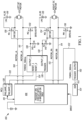
- FIG. 1 depicts an apparatus 100 for releasing one or both electric motors of an electric motor-driven parking brake system in a motor vehicle equipped with a so-called integrated parking brake or "IPB" system.
- An electric motor-driven parking brake comprises of course, two reversible motors 102, 104, the output shafts of which are omitted from FIG. 1 as they are superfluous to the invention described and claimed herein.
- the motors 102, 104 rotate in a first direction, either clockwise or counter clockwise as a design choice, they exert tension on a parking brake cable. Reversing the motors 102, 104 releases tension on the cable which releases the parking brake or unwinds a gear to release the brake, depending on the parking brake design.
- An integrated parking brake controller 106 provides electric driving current to the motors 102, 104 through corresponding drive wires 108, 110 and 112, 114.
- the motors 102, 104 are to be driven in a first direction, the electric current provided to the motors on the drive wires travels in a first direction.
- the motors need to be reversed, the polarity of the current is reversed.
- the integrated brake controller 106 fails, one or both motors can be rendered inoperative.
- the apparatus for releasing an electric motor-driven parking brake in a motor vehicle comprises a processor 120 operatively coupled to the integrated parking brake controller 106 through a control wire or control "line" 119.
- a fail signal is provided to the processor 120 through the control line 119, which indicates to the processor 120that the integrated parking brake controller 106 has failed and unlikely or unable to provide electrical energy to the electric motors 102 and 104.
- the processor 120 is configured to provide a "backup" parking brake release current to one or both motors 102, 104 through switches embodied as field effect transistors (FET), the polarity or direction of the parking brake release current being selected in advance such that the motors will only reverse, i.e. the motors will only release the parking brake, when the FETs "close” or are driven to their conducting states.
- FET field effect transistors
- the FETs are considered to be electronically controlled, normally-open switches, which are connected between the motors 102, 104 and a current source such that when the switches "close,” they provide battery power 118 to the motors 102, 104.
- the battery power 118 causes the motors to release the parking brake.
- the electronically controlled, normally-open switches are embodied as field effect transistors connected in parallel to the current supply lines 108, 110 and 112, 114 that extend from the integrated parking brake controller 106 to the motors armatures.
- a first NMOS transistor 130 has its drain terminal connected to the battery and its source terminal connected to the armature of the first motor 102. The gate is operatively coupled to the processor 120 through a timer 126, the function of which will be explained later.
- a second NMOS transistor 132 has its drain connected to the opposite armature of the first motor 102 and its source connected to ground. Its gate is also coupled to the processor 120 through the aforementioned timer 126. When a control signal 128 goes “active” or “high” both NMOS transistors turn “on” applying the battery voltage 118 to one armature and ground to the second armature, the result of which is energizing the motor 102.
- PMOS transistors are used. Unlike an NMOS transistor, the PMOS transistors conduct when their gate voltages go “low.” The polarity of the control signal 128 should therefore go “low” or inactive to turn the motors on.
- emergency power is provided to the other motor 104 in the same way.
- Two NMOS transistors 134 and 136 apply battery voltage and ground to the armatures of the second motor 104. Turning those transistors on thus enables the second motor to also become energized.
- the control signals 128 are provided to the NMOS transistors only after a first timer 126 has determined that a pre-determined amount of time has elapsed after the vehicle's ignition indicates that the vehicle is starting. That pre-determined wait or delay time that the apparatus 100 waits is determined by a second timer 150, which receives an ignition signal 152 from an ignition actuation switch 154. Stated another way, when the ignition switch 154 shows that the vehicle is being started, an ignition signal 152 is provided to the timer 150. At the expiration of the timer 150, a signal 152 is sent to the first timer 126 triggering it to begin a wait time for a signal from the processor 120 to reset.
- the outputs 128 of the first timer 126 go high or active causing the motors to turn on and release the parking brake.
- the apparatus shown in FIG. 1 thus automatically releases the parking brake of an integrated parking brake-equipped vehicle if the driver does not release the parking brake or if an integrated parking brake controller 106 fails.
- a relatively complex electronic parking brake system is thus made more reliable by including a "fail safe" release circuit 100 which provides a redundant apparatus by which the parking brakes in such a system can be released.
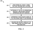
- FIG. 2 depicts steps of a method 200 for releasing an integrated parking brake using a redundant integrated parking brake release circuit, such as the one shown in FIG. 1 .
- a "first" timer is started when the vehicle's ignition is actuated or the operating state of the vehicle is otherwise changed responsive to a driver's intention to move the vehicle.
Landscapes
- Engineering & Computer Science (AREA)
- Mechanical Engineering (AREA)
- Transportation (AREA)
- Power Engineering (AREA)
- General Engineering & Computer Science (AREA)
- Valves And Accessory Devices For Braking Systems (AREA)
- Regulating Braking Force (AREA)
Description
- A motor vehicle's parking brake is used to keep a vehicle stationary and in some cases perform an emergency stop. They are typically embodied as either a pedal or handle, which when depressed or lifted respectively, pulls a cable that applies force to one or two wheel brakes of a vehicle causing them to engage and hold the vehicle stationary.
- Some vehicles are now provided with electronic brakes or "e-brakes," also known as integrated parking brakes. They replace a simple and reliable prior-art parking brake with a complex system of electric motors and motor controllers.
- Activation of a parking brake in a vehicles with integrated parking brakes or "e-brakes" is accomplished using a push button on a vehicle's dashboard or elsewhere, sending a signal to an electronic device which actuates electric motors to engage the brakes. Releasing the brakes in an e-brake vehicle requires another push button actuation. Unfortunately, when electronic devices fail, as they are known to do, the parking brakes in an e-brake equipped vehicle cannot be released. And, since the electric motor-operated brakes typically apply a much greater brake actuating force, a e-brake will usually lock the wheels solidly. An apparatus for releasing the mechanical brakes in a vehicle provided with an e-brake system or "integrated parking brake" system would be an improvement over the prior art.
US 2017/0108067 A1 discloses an electric brake device that cancels a residual pressure of a braking force, when there is an abnormality in the power supply. When there ist not enough energy left in the power supply device, a connection with the power supply device is broken and an electric motor for canceling the pressure is driven using power of a sub-power supply device. - An apparatus for releasing an electric motor-driven parking brake of a motor vehicle, the electric motor-driven parking brake including a mechanical parking brake, which is applied and released by controlling the operation and direction of an electric motor that is mechanically coupled to the mechanical parking brake, the electric motor being normally driven by a first electrical energy source, the apparatus according to an exemplary embodiment of this disclosure, among other possible things includes a processor configured to receive a parking brake power supply failure signal, which when received, it indicates to the processor that the first electrical energy source is unable to provide electrical energy to the electric motor and an electronically controlled, normally-open switch connected between a second electrical energy source and the electric motor, the normally-open switch being operatively coupled to the processor and capable of closing and opening responsive to a control signal from the processor. The processor configured to send a parking brake release control signal to the electronically controlled, normally-open switch upon the processor's receipt of the parking brake power supply failure signal, the parking brake release control signal causing the electronically controlled, normally-open switch to close and thereby provide electrical energy to the motor.
- In a further embodiment of the foregoing apparatus, the normally-open switch comprises a transistor and wherein the second electrical energy source is a battery.
- In a further embodiment of any of the foregoing apparatuses the processor, the motor, the electronically controlled, normally-open switch and the second electrical energy source are selected and arranged to provide electrical energy to the electric motor that will cause the electric motor to rotate in only one direction when the electric motor receives electrical energy from the second power source, the one direction causing the parking brake to release.
- In a further embodiment of any of the foregoing apparatuses, including an integrated parking brake controller includes an output connected to the electric motor, the output of the integrated parking brake controller provides first and second output voltages, which cause the motor to apply and release the parking brake respectively.
- The invention, including first and second timers connected in series, the first and second timers enabling and disabling the actuation of the electronically controlled, normally-open switch, wherein the first timer is started when the motor vehicle ignition is turned on and runs until the expiration of a predetermined amount of time the expiration of which is followed by a signal being sent to the second timer to begin a wait time for reset signal.
- In a further embodiment of any of the foregoing apparatuses, an output from the first timer goes active to cause the motor to turn on and release the parking brake in response to failure to receive the reset signal.
- An electric motor-driven parking brake system for a motor vehicle according to another exemplary embodiment of this disclosure, among other possible things includes mechanical parking brake coupled to an electric motor, wherein the mechanical parking brake is applied and released by controlling operation and direction of the electric motor, an electric energy source driving operation of the electric motor and a controller controlling operation of the electric motor to release the parking brake. The controller including, a processor configured to receive a parking brake power supply failure signal, which when received, it indicates to the processor that the first electrical energy source is unable to provide electrical energy to the electric motor, an electronically controlled, normally-open switch connected between a second electrical energy source and the electric motor, the normally-open switch being operatively coupled to the processor and capable of closing and opening responsive to a control signal from the processor, wherein, the processor is configured to send a parking brake release control signal to the electronically controlled, normally-open switch upon the processor's receipt of the parking brake power supply failure signal, the parking brake release control signal causing the electronically controlled, normally-open switch to close and thereby provide electrical energy to the motor.
- In a further embodiment of the foregoing electric motor-driven parking brake system the electronically controlled, normally-open switch comprises a transistor and the second electrical energy source is a battery.
- In a further embodiment of any of the foregoing electric motor-driven parking brake systems, the processor, the motor, the electronically controlled, normally-open switch and the second electrical energy source are selected and arranged to provide electrical energy to the electric motor that will cause the electric motor to rotate in only one direction when the electric motor receives electrical energy from the second power source, the one direction causing the parking brake to release.
- In a further embodiment of any of the foregoing electric motor-driven parking brake systems, an integrated parking brake controller includes an output connected to the electric motor, the output of the integrated parking brake controller provides first and second output voltages, which cause the motor to apply and release the parking brake respectively
- According to the invention, first and second timers are connected in series, the first and second timers enabling and disabling the actuation of the electronically controlled, normally-open switch, wherein the first timer is started when the motor vehicle ignition is turned on and runs until the expiration of a predetermined amount of time the expiration of which is followed by a signal being sent to the second timer to begin a wait time for reset signal.
- In a further embodiment of any of the foregoing electric motor-driven parking brake systems, an output from the first timer goes active to cause the motor to turn on and release the parking brake in response to failure to receive the reset signal.
- A method of controlling an electric motor-driven parking brake system for a motor vehicle according to another example embodiment includes, among other possible things, starting a timer in response to an action demonstrating an intention to move the motor vehicle, determining an operational state of an engine control unit, determining an operational state of an electric motor coupled to a parking brake, determining if the parking brake requires release and providing a current to operate the electric motor to release the parking brake.
- In a further embodiment of the foregoing method, the action demonstrating an intention to move the motor vehicle comprises actuation of an ignition of the motor vehicle.
- In a further embodiment of any of the forgoing methods, the electric motor is powered through a release circuit responsive to the timer expiring without receiving an indication that the parking brake has been released.
- Although the different examples have the specific components shown in the illustrations, embodiments of this disclosure are not limited to those particular combinations. It is possible to use some of the components or features from one of the examples in combination with features or components from another one of the examples.
- These and other features disclosed herein can be best understood from the following specification and drawings, the following of which is a brief description.
-
-
FIG. 1 is a block diagram of an apparatus for releasing an electric motor-driven parking brake in an integrated parking brake-equipped vehicle, when the integrated parking brake electronics fail; and -
FIG. 2 is a flow chart depicting steps of a method. -
FIG. 1 depicts anapparatus 100 for releasing one or both electric motors of an electric motor-driven parking brake system in a motor vehicle equipped with a so-called integrated parking brake or "IPB" system. An electric motor-driven parking brake comprises of course, tworeversible motors 102, 104, the output shafts of which are omitted fromFIG. 1 as they are superfluous to the invention described and claimed herein. When themotors 102, 104 rotate in a first direction, either clockwise or counter clockwise as a design choice, they exert tension on a parking brake cable. Reversing themotors 102, 104 releases tension on the cable which releases the parking brake or unwinds a gear to release the brake, depending on the parking brake design. - An integrated
parking brake controller 106 provides electric driving current to themotors 102, 104 throughcorresponding drive wires motors 102, 104 are to be driven in a first direction, the electric current provided to the motors on the drive wires travels in a first direction. When the motors need to be reversed, the polarity of the current is reversed. Unfortunately, when the integratedbrake controller 106 fails, one or both motors can be rendered inoperative. - In the preferred embodiment, the apparatus for releasing an electric motor-driven parking brake in a motor vehicle comprises a
processor 120 operatively coupled to the integratedparking brake controller 106 through a control wire or control "line" 119. Put simply, when the integratedparking brake controller 106 fails, a fail signal is provided to theprocessor 120 through thecontrol line 119, which indicates to the processor 120that the integratedparking brake controller 106 has failed and unlikely or unable to provide electrical energy to theelectric motors 102 and 104. - When the integrated
parking brake controller 106 fails, theprocessor 120 is configured to provide a "backup" parking brake release current to one or bothmotors 102, 104 through switches embodied as field effect transistors (FET), the polarity or direction of the parking brake release current being selected in advance such that the motors will only reverse, i.e. the motors will only release the parking brake, when the FETs "close" or are driven to their conducting states. - The FETs are considered to be electronically controlled, normally-open switches, which are connected between the
motors 102, 104 and a current source such that when the switches "close," they providebattery power 118 to themotors 102, 104. Thebattery power 118 causes the motors to release the parking brake. - In a preferred embodiment, the electronically controlled, normally-open switches are embodied as field effect transistors connected in parallel to the
current supply lines parking brake controller 106 to the motors armatures. Afirst NMOS transistor 130 has its drain terminal connected to the battery and its source terminal connected to the armature of thefirst motor 102. The gate is operatively coupled to theprocessor 120 through atimer 126, the function of which will be explained later. - A
second NMOS transistor 132 has its drain connected to the opposite armature of thefirst motor 102 and its source connected to ground. Its gate is also coupled to theprocessor 120 through theaforementioned timer 126. When acontrol signal 128 goes "active" or "high" both NMOS transistors turn "on" applying thebattery voltage 118 to one armature and ground to the second armature, the result of which is energizing themotor 102. - In an alternate embodiment, PMOS transistors are used. Unlike an NMOS transistor, the PMOS transistors conduct when their gate voltages go "low." The polarity of the
control signal 128 should therefore go "low" or inactive to turn the motors on. - In
FIG. 1 , emergency power is provided to the other motor 104 in the same way. TwoNMOS transistors - The
control signals 128 are provided to the NMOS transistors only after afirst timer 126 has determined that a pre-determined amount of time has elapsed after the vehicle's ignition indicates that the vehicle is starting. That pre-determined wait or delay time that theapparatus 100 waits is determined by asecond timer 150, which receives anignition signal 152 from anignition actuation switch 154. Stated another way, when theignition switch 154 shows that the vehicle is being started, anignition signal 152 is provided to thetimer 150. At the expiration of thetimer 150, asignal 152 is sent to thefirst timer 126 triggering it to begin a wait time for a signal from theprocessor 120 to reset. If the reset signals 122 and 124 are not received within the pre-determined time after thetrigger signal 152 is received by thefirst timer 126, theoutputs 128 of thefirst timer 126 go high or active causing the motors to turn on and release the parking brake. The apparatus shown inFIG. 1 thus automatically releases the parking brake of an integrated parking brake-equipped vehicle if the driver does not release the parking brake or if an integratedparking brake controller 106 fails. A relatively complex electronic parking brake system is thus made more reliable by including a "fail safe"release circuit 100 which provides a redundant apparatus by which the parking brakes in such a system can be released. - Finally,
FIG. 2 depicts steps of amethod 200 for releasing an integrated parking brake using a redundant integrated parking brake release circuit, such as the one shown inFIG. 1 . - At a
first step 202, a "first" timer is started when the vehicle's ignition is actuated or the operating state of the vehicle is otherwise changed responsive to a driver's intention to move the vehicle. At thenext step 204, a determination is made whether the vehicle's engine control unit or "ECU" (where the IPB controller is typically located) is operational and whether either of the motors' interfaces are inoperative, i.e., whether one or both motor interfaces are working. - At
step 206, a determination is made whether one or both sides of the parking brakes need to be released. If so, atstep 208, the parking brakes that need to be released, i.e., left, right or both, are released by providing the current to reverse the corresponding motor(s). - The foregoing description is for purposes of illustration only. The true scope of the invention is set forth in the following claims.
Claims (12)
- An apparatus for releasing an electric motor-driven parking brake of a motor vehicle, the electric motor-driven parking brake comprising a mechanical parking brake, which is applied and released by controlling the operation and direction of an electric motor (102, 104) that is mechanically coupled to the mechanical parking brake, the electric motor being normally driven by a first electrical energy source, the apparatus comprising:a processor (120) configured to receive a parking brake power supply failure signal, which when received, it indicates to the processor (120) that the first electrical energy source is unable to provide electrical energy to the electric motor (102, 104),characterized in that the apparatus further comprising:an electronically controlled, normally-open switch (130, 132) connected between a second electrical energy source and the electric motor (102, 104), the normally-open switch (130, 132) being operatively coupled to the processor (120) and capable of closing and opening responsive to a control signal from the processor (120);wherein, the processor (120) is configured to send a parking brake release control signal to the electronically controlled, normally-open switch (130, 132) upon the processor's receipt of the parking brake power supply failure signal, the parking brake release control signal causing the electronically controlled, normally-open switch (130, 132) to close and thereby provide electrical energy to the motor (102, 104)further comprising first and second timers (126, 150) connected in series, the first and second timers (126, 150) enabling and disabling the actuation of the electronically controlled, normally-open switch, wherein the first timer (126) is started when the motor vehicle ignition is turned on and runs until the expiration of a predetermined amount of time the expiration of which is followed by a signal being sent to the second timer (150) to begin a wait time for reset signal.
- The apparatus of claim 1, wherein the electronically controlled, normally-open switch comprises a transistor and wherein the second electrical energy source is a battery.
- The apparatus of claim 2, wherein the processor (120), the motor (102, 104), the electronically controlled, normally-open switch (130, 132) and the second electrical energy source are selected and arranged to provide electrical energy to the electric motor (102, 104) that will cause the electric motor (102, 104) to rotate in only one direction when the electric motor (102, 104) receives electrical energy from the second power source, the one direction causing the parking brake to release.
- The apparatus of claim 3, further comprising an integrated parking brake controller, an output of which is connected to the electric motor (102, 104), the output of the integrated parking brake controller providing a first and second output voltages, which cause the motor (102, 104) to apply and release the parking brake respectively.
- The apparatus of one of the claims 1 to 4, wherein an output from the first timer (126) goes active to cause the motor (102, 104) to turn on and release the parking brake in response to failure to receive the reset signal.
- An electric motor-driven parking brake system for a motor vehicle comprising: a mechanical parking brake coupled to an electric motor (102, 104), wherein the mechanical parking brake is applied and released by controlling operation and direction of the electric motor (102, 104); an electric energy source driving operation of the electric motor (102, 104); and a controller controlling operation of the electric motor (102, 104) to release the parking brake, the controller including, a processor (120) configured to receive a parking brake power supply failure signal, which when received, it indicates to the processor (120) that the first electrical energy source is unable to provide electrical energy to the electric motor (102), characteried by an electronically controlled, normally-open switch (130, 132) connected between a second electrical energy source and the electric motor (102, 104), the normally-open switch (130, 132) being operatively coupled to the processor (120) and capable of closing and opening responsive to a control signal from the processor (120) , wherein, the processor (120) is configured to send a parking brake release control signal to the electronically controlled, normally-open switch (130, 132) upon the processor's receipt of the parking brake power supply failure signal, the parking brake release control signal causing the electronically controlled, normally-open switch (130, 132) to close and thereby provide electrical energy to the motor (102, 104), and first and second timers (126, 150) connected in series, the first and second timers (126, 150) enabling and disabling the actuation of the electronically controlled, normally-open switch (130, 132), wherein the first timer (126) is started when the motor vehicle ignition is turned on and runs until the expiration of a predetermined amount of time the expiration of which is followed by a signal being sent to the second timer (150) to begin a wait time for reset signal.
- The electric motor-driven parking brake system of claim 6, wherein the electronically controlled, normally-open switch (130, 132) comprises a transistor and wherein the second electrical energy source is a battery.
- The electric motor-driven parking brake system of claim 7, wherein the processor (120), the motor (102, 104), the electronically controlled, normally-open switch (130, 132) and the second electrical energy source are selected and arranged to provide electrical energy to the electric motor (102, 104) that will cause the electric motor (102, 104) to rotate in only one direction when the electric motor (102, 104) receives electrical energy from the second power source, the one direction causing the parking brake to release.
- The electric motor-driven parking brake system of claim 8, further comprising an integrated parking brake controller, an output of which is connected to the electric motor (102, 104) , the output of the integrated parking brake controller providing a first and second output voltages, which cause the motor (102, 104) to apply and release the parking brake respectively.
- A method of controlling an electric motor-driven parking brake system for a motor vehicle comprising: starting a timer (126) in response to an action demonstrating an intention to move the motor vehicle; determining an operational state of an engine control unit; determining an operational state of an electric motor (102, 104) coupled to a parking brake; determining if the parking brake requires release; and for an apparatus providing a current to operate the electric motor (102, 104) to release the parking brake the apparatus comprises a processor (120) configured to receive a parking brake power supply failure signal, which when received, it indicates to the processor (120) that the first electrical energy source is unable to provide electrical energy to the electric motor (102, 104),an electronically controlled, normally-open switch (130, 132) connected between a second electrical energy source and the electric motor (102, 104), the normally-open switch (130, 132) being operatively coupled to the processor (120 and capable of closing and opening responsive to a control signal from the processor (120), wherein, the processor (120) is configured to send a parking brake release control signal to the electronically controlled, normally-open switch (130, 132) upon the processor's receipt of the parking brake power supply failure signal, the parking brake release control signal causing the electronically controlled, normally-open switch (130, 132) to close and thereby provide electrical energy to the motor (102, 104), andfirst and second timers (126, 150) connected in series, the first and second timers (126, 150) enabling and disabling the actuation of the electronically controlled, normally-open switch (130, 132), wherein the first timer (126) is started when the motor vehicle ignition is turned on and runs until the expiration of a predetermined amount of time the expiration of which is followed by a signal being sent to the second timer (150) to begin a wait time for reset signal..
- The method as recited in claim 10, wherein the action demonstrating an intention to move the motor vehicle comprises actuation of an ignition of the motor vehicle.
- The method as recited in claim 11, including the step of powering the electric motor through a release circuit responsive to the timer expiring without receiving an indication that the parking brake has been released.
Applications Claiming Priority (3)
| Application Number | Priority Date | Filing Date | Title |
|---|---|---|---|
| US201762581473P | 2017-11-03 | 2017-11-03 | |
| US16/177,823 US10829101B2 (en) | 2017-11-03 | 2018-11-01 | Redundant integrated parking brake release circuit |
| PCT/US2018/059030 WO2019090128A1 (en) | 2017-11-03 | 2018-11-02 | Redundant integrated parking brake release circuit |
Publications (2)
| Publication Number | Publication Date |
|---|---|
| EP3703988A1 EP3703988A1 (en) | 2020-09-09 |
| EP3703988B1 true EP3703988B1 (en) | 2023-08-30 |
Family
ID=64402283
Family Applications (1)
| Application Number | Title | Priority Date | Filing Date |
|---|---|---|---|
| EP18807183.1A Active EP3703988B1 (en) | 2017-11-03 | 2018-11-02 | Redundant integrated parking brake release circuit |
Country Status (3)
| Country | Link |
|---|---|
| US (1) | US10829101B2 (en) |
| EP (1) | EP3703988B1 (en) |
| WO (1) | WO2019090128A1 (en) |
Families Citing this family (6)
| Publication number | Priority date | Publication date | Assignee | Title |
|---|---|---|---|---|
| KR102638257B1 (en) * | 2016-10-18 | 2024-02-20 | 에이치엘만도 주식회사 | electronic parking brake system and control method thereof |
| DE102020107548A1 (en) * | 2020-03-19 | 2021-09-23 | Ford Global Technologies Llc | Motor vehicle and method for operating a motor vehicle |
| JP7331797B2 (en) * | 2020-07-08 | 2023-08-23 | トヨタ自動車株式会社 | vehicle controller |
| CN113928365B (en) * | 2021-11-17 | 2024-02-27 | 中车南京浦镇车辆有限公司 | Circuit for reliably outputting brake release application state of rail transit vehicle |
| CN115158279B (en) * | 2022-09-07 | 2022-12-06 | 万向钱潮股份公司 | Electronic parking auxiliary control method and redundancy control system |
| CN117984973A (en) * | 2022-10-27 | 2024-05-07 | 华为技术有限公司 | Braking system of vehicle, vehicle and control method |
Family Cites Families (13)
| Publication number | Priority date | Publication date | Assignee | Title |
|---|---|---|---|---|
| DE19962556A1 (en) | 1999-12-23 | 2001-07-19 | Daimler Chrysler Ag | Arrangement for actuating vehicle electrical parking brake has redundant electrical switching devices decoupled in direction of motion for detecting parking brake applied, released |
| US6969127B2 (en) * | 2003-04-11 | 2005-11-29 | Asmo Co., Ltd. | Electric parking brake system |
| JPWO2005110814A1 (en) | 2004-05-13 | 2008-03-21 | 株式会社日立製作所 | Electric brake system |
| JP5000893B2 (en) | 2005-01-27 | 2012-08-15 | 日立オートモティブシステムズ株式会社 | Electric brake control device and electric brake control method |
| DE102007029632A1 (en) * | 2006-06-27 | 2008-01-10 | Continental Teves Ag & Co. Ohg | Parking brake system for motor vehicle, has control element and two electromechanical actuators for generating parking brake force on respective wheel of vehicle, where control element is connected to electromechanical actuators |
| US7850254B2 (en) * | 2007-02-20 | 2010-12-14 | Bwi Company Limited S.A. | Extreme emergency braking systems for brake-by-wire brake systems |
| DE102008018946A1 (en) * | 2008-04-15 | 2009-10-22 | Lucas Automotive Gmbh | Technique for releasing an electric parking brake |
| DE102011084534A1 (en) | 2010-10-18 | 2012-04-19 | Continental Teves Ag & Co. Ohg | Fail-safe parking brake for motor vehicles |
| DE102011086756A1 (en) | 2010-11-23 | 2012-05-24 | Continental Teves Ag & Co. Ohg | Method for fault detection of a control switch for triggering a vehicle function of a vehicle and control switch for performing the method |
| DE102014204287A1 (en) | 2014-03-07 | 2015-09-10 | Robert Bosch Gmbh | Method for operating a motor vehicle brake device and control device for a motor vehicle brake device |
| US10286891B2 (en) | 2014-07-11 | 2019-05-14 | Ford Global Technologies, Llc | Vehicle parking system failure management |
| JP6313152B2 (en) | 2014-07-18 | 2018-04-18 | Ntn株式会社 | Electric brake device |
| DE102015114176C5 (en) | 2015-08-26 | 2020-07-16 | Knorr-Bremse Systeme für Nutzfahrzeuge GmbH | Electric parking brake device with additional energy supply |
-
2018
- 2018-11-01 US US16/177,823 patent/US10829101B2/en active Active
- 2018-11-02 EP EP18807183.1A patent/EP3703988B1/en active Active
- 2018-11-02 WO PCT/US2018/059030 patent/WO2019090128A1/en unknown
Also Published As
| Publication number | Publication date |
|---|---|
| US10829101B2 (en) | 2020-11-10 |
| WO2019090128A1 (en) | 2019-05-09 |
| EP3703988A1 (en) | 2020-09-09 |
| US20190193707A1 (en) | 2019-06-27 |
Similar Documents
| Publication | Publication Date | Title |
|---|---|---|
| EP3703988B1 (en) | Redundant integrated parking brake release circuit | |
| US10315631B2 (en) | Method for operating a motor vehicle brake system, and a control device for a motor vehicle brake system | |
| EP1424255B1 (en) | Electro mechanical brake, control device and control methods | |
| CN109789870B (en) | Backup device for vehicle | |
| JP2000515955A (en) | Actuator of control device in automobile | |
| KR20140068151A (en) | Drive assembly for the motorized adjustment of an adjusting element of a motor vehicle | |
| KR101633147B1 (en) | Method for operating a braking system, braking system and motor vehicle having braking system | |
| US10029680B2 (en) | Method and device for handing over a motor vehicle to the driver during an automatic parking space-leaving maneuver | |
| CN110949500B (en) | Automobile and control method thereof | |
| JP2006264384A (en) | Electric parking brake system | |
| CN110949501B (en) | Steering clutch, steering column, steering system and control method thereof | |
| US11112008B2 (en) | Vehicle control device | |
| KR20220119493A (en) | Braking system with redundant parking brake operation | |
| JP2019093962A5 (en) | ||
| KR101240893B1 (en) | Motor drive circuit of electric parking brake and controlling method thereof | |
| CN107531271B (en) | Electric power steering apparatus | |
| JP2017506196A (en) | Method for operating a steering system | |
| KR20150092448A (en) | Electronic parking brake apparatus and control method therefor | |
| JP2014024389A (en) | Vehicular control unit | |
| KR20080087472A (en) | Electronic parking brake system | |
| US6398320B1 (en) | Vehicle braking system with auxiliary activation circuit | |
| JP3672524B2 (en) | Power supply circuit for actuator of in-vehicle travel controller | |
| JPH1189276A (en) | Braking force controller | |
| KR20070032484A (en) | The actuator for drive by wire of car | |
| KR101309509B1 (en) | Motor drive circuit of electric parking brake |
Legal Events
| Date | Code | Title | Description |
|---|---|---|---|
| STAA | Information on the status of an ep patent application or granted ep patent |
Free format text: STATUS: UNKNOWN |
|
| STAA | Information on the status of an ep patent application or granted ep patent |
Free format text: STATUS: THE INTERNATIONAL PUBLICATION HAS BEEN MADE |
|
| PUAI | Public reference made under article 153(3) epc to a published international application that has entered the european phase |
Free format text: ORIGINAL CODE: 0009012 |
|
| STAA | Information on the status of an ep patent application or granted ep patent |
Free format text: STATUS: REQUEST FOR EXAMINATION WAS MADE |
|
| 17P | Request for examination filed |
Effective date: 20200603 |
|
| AK | Designated contracting states |
Kind code of ref document: A1 Designated state(s): AL AT BE BG CH CY CZ DE DK EE ES FI FR GB GR HR HU IE IS IT LI LT LU LV MC MK MT NL NO PL PT RO RS SE SI SK SM TR |
|
| AX | Request for extension of the european patent |
Extension state: BA ME |
|
| RAP1 | Party data changed (applicant data changed or rights of an application transferred) |
Owner name: CONTINENTAL AUTOMOTIVE SYSTEMS, INC. |
|
| DAV | Request for validation of the european patent (deleted) | ||
| DAX | Request for extension of the european patent (deleted) | ||
| STAA | Information on the status of an ep patent application or granted ep patent |
Free format text: STATUS: EXAMINATION IS IN PROGRESS |
|
| 17Q | First examination report despatched |
Effective date: 20220622 |
|
| GRAP | Despatch of communication of intention to grant a patent |
Free format text: ORIGINAL CODE: EPIDOSNIGR1 |
|
| STAA | Information on the status of an ep patent application or granted ep patent |
Free format text: STATUS: GRANT OF PATENT IS INTENDED |
|
| INTG | Intention to grant announced |
Effective date: 20230405 |
|
| GRAS | Grant fee paid |
Free format text: ORIGINAL CODE: EPIDOSNIGR3 |
|
| GRAA | (expected) grant |
Free format text: ORIGINAL CODE: 0009210 |
|
| STAA | Information on the status of an ep patent application or granted ep patent |
Free format text: STATUS: THE PATENT HAS BEEN GRANTED |
|
| REG | Reference to a national code |
Ref country code: DE Ref legal event code: R081 Ref document number: 602018056542 Country of ref document: DE Owner name: CONTINENTAL AUTOMOTIVE SYSTEMS, INC., AUBURN H, US Free format text: FORMER OWNER: CONTINENTAL AUTONOMOUS MOBILITY US, LLC (N.D.GES.D.STAATES DELAWARE), AUBURN HILLS, MI, US |
|
| AK | Designated contracting states |
Kind code of ref document: B1 Designated state(s): AL AT BE BG CH CY CZ DE DK EE ES FI FR GB GR HR HU IE IS IT LI LT LU LV MC MK MT NL NO PL PT RO RS SE SI SK SM TR |
|
| REG | Reference to a national code |
Ref country code: GB Ref legal event code: FG4D |
|
| REG | Reference to a national code |
Ref country code: CH Ref legal event code: EP |
|
| REG | Reference to a national code |
Ref country code: DE Ref legal event code: R096 Ref document number: 602018056542 Country of ref document: DE |
|
| REG | Reference to a national code |
Ref country code: IE Ref legal event code: FG4D |
|
| REG | Reference to a national code |
Ref country code: LT Ref legal event code: MG9D |
|
| REG | Reference to a national code |
Ref country code: NL Ref legal event code: MP Effective date: 20230830 |
|
| REG | Reference to a national code |
Ref country code: AT Ref legal event code: MK05 Ref document number: 1605063 Country of ref document: AT Kind code of ref document: T Effective date: 20230830 |
|
| PG25 | Lapsed in a contracting state [announced via postgrant information from national office to epo] |
Ref country code: GR Free format text: LAPSE BECAUSE OF FAILURE TO SUBMIT A TRANSLATION OF THE DESCRIPTION OR TO PAY THE FEE WITHIN THE PRESCRIBED TIME-LIMIT Effective date: 20231201 |
|
| PG25 | Lapsed in a contracting state [announced via postgrant information from national office to epo] |
Ref country code: IS Free format text: LAPSE BECAUSE OF FAILURE TO SUBMIT A TRANSLATION OF THE DESCRIPTION OR TO PAY THE FEE WITHIN THE PRESCRIBED TIME-LIMIT Effective date: 20231230 |
|
| PG25 | Lapsed in a contracting state [announced via postgrant information from national office to epo] |
Ref country code: SE Free format text: LAPSE BECAUSE OF FAILURE TO SUBMIT A TRANSLATION OF THE DESCRIPTION OR TO PAY THE FEE WITHIN THE PRESCRIBED TIME-LIMIT Effective date: 20230830 Ref country code: RS Free format text: LAPSE BECAUSE OF FAILURE TO SUBMIT A TRANSLATION OF THE DESCRIPTION OR TO PAY THE FEE WITHIN THE PRESCRIBED TIME-LIMIT Effective date: 20230830 Ref country code: NO Free format text: LAPSE BECAUSE OF FAILURE TO SUBMIT A TRANSLATION OF THE DESCRIPTION OR TO PAY THE FEE WITHIN THE PRESCRIBED TIME-LIMIT Effective date: 20231130 Ref country code: LV Free format text: LAPSE BECAUSE OF FAILURE TO SUBMIT A TRANSLATION OF THE DESCRIPTION OR TO PAY THE FEE WITHIN THE PRESCRIBED TIME-LIMIT Effective date: 20230830 Ref country code: LT Free format text: LAPSE BECAUSE OF FAILURE TO SUBMIT A TRANSLATION OF THE DESCRIPTION OR TO PAY THE FEE WITHIN THE PRESCRIBED TIME-LIMIT Effective date: 20230830 Ref country code: IS Free format text: LAPSE BECAUSE OF FAILURE TO SUBMIT A TRANSLATION OF THE DESCRIPTION OR TO PAY THE FEE WITHIN THE PRESCRIBED TIME-LIMIT Effective date: 20231230 Ref country code: HR Free format text: LAPSE BECAUSE OF FAILURE TO SUBMIT A TRANSLATION OF THE DESCRIPTION OR TO PAY THE FEE WITHIN THE PRESCRIBED TIME-LIMIT Effective date: 20230830 Ref country code: GR Free format text: LAPSE BECAUSE OF FAILURE TO SUBMIT A TRANSLATION OF THE DESCRIPTION OR TO PAY THE FEE WITHIN THE PRESCRIBED TIME-LIMIT Effective date: 20231201 Ref country code: FI Free format text: LAPSE BECAUSE OF FAILURE TO SUBMIT A TRANSLATION OF THE DESCRIPTION OR TO PAY THE FEE WITHIN THE PRESCRIBED TIME-LIMIT Effective date: 20230830 Ref country code: AT Free format text: LAPSE BECAUSE OF FAILURE TO SUBMIT A TRANSLATION OF THE DESCRIPTION OR TO PAY THE FEE WITHIN THE PRESCRIBED TIME-LIMIT Effective date: 20230830 |
|
| PGFP | Annual fee paid to national office [announced via postgrant information from national office to epo] |
Ref country code: FR Payment date: 20231120 Year of fee payment: 6 Ref country code: DE Payment date: 20231130 Year of fee payment: 6 |
|
| PG25 | Lapsed in a contracting state [announced via postgrant information from national office to epo] |
Ref country code: PL Free format text: LAPSE BECAUSE OF FAILURE TO SUBMIT A TRANSLATION OF THE DESCRIPTION OR TO PAY THE FEE WITHIN THE PRESCRIBED TIME-LIMIT Effective date: 20230830 Ref country code: NL Free format text: LAPSE BECAUSE OF FAILURE TO SUBMIT A TRANSLATION OF THE DESCRIPTION OR TO PAY THE FEE WITHIN THE PRESCRIBED TIME-LIMIT Effective date: 20230830 |
|
| PG25 | Lapsed in a contracting state [announced via postgrant information from national office to epo] |
Ref country code: ES Free format text: LAPSE BECAUSE OF FAILURE TO SUBMIT A TRANSLATION OF THE DESCRIPTION OR TO PAY THE FEE WITHIN THE PRESCRIBED TIME-LIMIT Effective date: 20230830 |
|
| PG25 | Lapsed in a contracting state [announced via postgrant information from national office to epo] |
Ref country code: SM Free format text: LAPSE BECAUSE OF FAILURE TO SUBMIT A TRANSLATION OF THE DESCRIPTION OR TO PAY THE FEE WITHIN THE PRESCRIBED TIME-LIMIT Effective date: 20230830 Ref country code: RO Free format text: LAPSE BECAUSE OF FAILURE TO SUBMIT A TRANSLATION OF THE DESCRIPTION OR TO PAY THE FEE WITHIN THE PRESCRIBED TIME-LIMIT Effective date: 20230830 Ref country code: ES Free format text: LAPSE BECAUSE OF FAILURE TO SUBMIT A TRANSLATION OF THE DESCRIPTION OR TO PAY THE FEE WITHIN THE PRESCRIBED TIME-LIMIT Effective date: 20230830 Ref country code: EE Free format text: LAPSE BECAUSE OF FAILURE TO SUBMIT A TRANSLATION OF THE DESCRIPTION OR TO PAY THE FEE WITHIN THE PRESCRIBED TIME-LIMIT Effective date: 20230830 Ref country code: DK Free format text: LAPSE BECAUSE OF FAILURE TO SUBMIT A TRANSLATION OF THE DESCRIPTION OR TO PAY THE FEE WITHIN THE PRESCRIBED TIME-LIMIT Effective date: 20230830 Ref country code: CZ Free format text: LAPSE BECAUSE OF FAILURE TO SUBMIT A TRANSLATION OF THE DESCRIPTION OR TO PAY THE FEE WITHIN THE PRESCRIBED TIME-LIMIT Effective date: 20230830 Ref country code: SK Free format text: LAPSE BECAUSE OF FAILURE TO SUBMIT A TRANSLATION OF THE DESCRIPTION OR TO PAY THE FEE WITHIN THE PRESCRIBED TIME-LIMIT Effective date: 20230830 Ref country code: PT Free format text: LAPSE BECAUSE OF FAILURE TO SUBMIT A TRANSLATION OF THE DESCRIPTION OR TO PAY THE FEE WITHIN THE PRESCRIBED TIME-LIMIT Effective date: 20240102 |