DE102015114176C5 - Electric parking brake device with additional energy supply - Google Patents
Electric parking brake device with additional energy supply Download PDFInfo
- Publication number
- DE102015114176C5 DE102015114176C5 DE102015114176.0A DE102015114176A DE102015114176C5 DE 102015114176 C5 DE102015114176 C5 DE 102015114176C5 DE 102015114176 A DE102015114176 A DE 102015114176A DE 102015114176 C5 DE102015114176 C5 DE 102015114176C5
- Authority
- DE
- Germany
- Prior art keywords
- electrical
- electronic control
- parking brake
- energy supply
- electrical energy
- Prior art date
- Legal status (The legal status is an assumption and is not a legal conclusion. Google has not performed a legal analysis and makes no representation as to the accuracy of the status listed.)
- Active
Links
Images


Classifications
-
- B—PERFORMING OPERATIONS; TRANSPORTING
- B60—VEHICLES IN GENERAL
- B60T—VEHICLE BRAKE CONTROL SYSTEMS OR PARTS THEREOF; BRAKE CONTROL SYSTEMS OR PARTS THEREOF, IN GENERAL; ARRANGEMENT OF BRAKING ELEMENTS ON VEHICLES IN GENERAL; PORTABLE DEVICES FOR PREVENTING UNWANTED MOVEMENT OF VEHICLES; VEHICLE MODIFICATIONS TO FACILITATE COOLING OF BRAKES
- B60T13/00—Transmitting braking action from initiating means to ultimate brake actuator with power assistance or drive; Brake systems incorporating such transmitting means, e.g. air-pressure brake systems
- B60T13/10—Transmitting braking action from initiating means to ultimate brake actuator with power assistance or drive; Brake systems incorporating such transmitting means, e.g. air-pressure brake systems with fluid assistance, drive, or release
- B60T13/66—Electrical control in fluid-pressure brake systems
- B60T13/68—Electrical control in fluid-pressure brake systems by electrically-controlled valves
- B60T13/683—Electrical control in fluid-pressure brake systems by electrically-controlled valves in pneumatic systems or parts thereof
-
- B—PERFORMING OPERATIONS; TRANSPORTING
- B60—VEHICLES IN GENERAL
- B60T—VEHICLE BRAKE CONTROL SYSTEMS OR PARTS THEREOF; BRAKE CONTROL SYSTEMS OR PARTS THEREOF, IN GENERAL; ARRANGEMENT OF BRAKING ELEMENTS ON VEHICLES IN GENERAL; PORTABLE DEVICES FOR PREVENTING UNWANTED MOVEMENT OF VEHICLES; VEHICLE MODIFICATIONS TO FACILITATE COOLING OF BRAKES
- B60T13/00—Transmitting braking action from initiating means to ultimate brake actuator with power assistance or drive; Brake systems incorporating such transmitting means, e.g. air-pressure brake systems
- B60T13/10—Transmitting braking action from initiating means to ultimate brake actuator with power assistance or drive; Brake systems incorporating such transmitting means, e.g. air-pressure brake systems with fluid assistance, drive, or release
- B60T13/24—Transmitting braking action from initiating means to ultimate brake actuator with power assistance or drive; Brake systems incorporating such transmitting means, e.g. air-pressure brake systems with fluid assistance, drive, or release the fluid being gaseous
- B60T13/26—Compressed-air systems
- B60T13/38—Brakes applied by springs or weights and released by compressed air
- B60T13/385—Control arrangements therefor
-
- B—PERFORMING OPERATIONS; TRANSPORTING
- B60—VEHICLES IN GENERAL
- B60T—VEHICLE BRAKE CONTROL SYSTEMS OR PARTS THEREOF; BRAKE CONTROL SYSTEMS OR PARTS THEREOF, IN GENERAL; ARRANGEMENT OF BRAKING ELEMENTS ON VEHICLES IN GENERAL; PORTABLE DEVICES FOR PREVENTING UNWANTED MOVEMENT OF VEHICLES; VEHICLE MODIFICATIONS TO FACILITATE COOLING OF BRAKES
- B60T13/00—Transmitting braking action from initiating means to ultimate brake actuator with power assistance or drive; Brake systems incorporating such transmitting means, e.g. air-pressure brake systems
- B60T13/10—Transmitting braking action from initiating means to ultimate brake actuator with power assistance or drive; Brake systems incorporating such transmitting means, e.g. air-pressure brake systems with fluid assistance, drive, or release
- B60T13/66—Electrical control in fluid-pressure brake systems
- B60T13/662—Electrical control in fluid-pressure brake systems characterised by specified functions of the control system components
-
- B—PERFORMING OPERATIONS; TRANSPORTING
- B60—VEHICLES IN GENERAL
- B60T—VEHICLE BRAKE CONTROL SYSTEMS OR PARTS THEREOF; BRAKE CONTROL SYSTEMS OR PARTS THEREOF, IN GENERAL; ARRANGEMENT OF BRAKING ELEMENTS ON VEHICLES IN GENERAL; PORTABLE DEVICES FOR PREVENTING UNWANTED MOVEMENT OF VEHICLES; VEHICLE MODIFICATIONS TO FACILITATE COOLING OF BRAKES
- B60T15/00—Construction arrangement, or operation of valves incorporated in power brake systems and not covered by groups B60T11/00 or B60T13/00
- B60T15/02—Application and release valves
- B60T15/18—Triple or other relay valves which allow step-wise application or release and which are actuated by brake-pipe pressure variation to connect brake cylinders or equivalent to compressed air or vacuum source or atmosphere
- B60T15/24—Triple or other relay valves which allow step-wise application or release and which are actuated by brake-pipe pressure variation to connect brake cylinders or equivalent to compressed air or vacuum source or atmosphere controlled by three fluid pressures
-
- B—PERFORMING OPERATIONS; TRANSPORTING
- B60—VEHICLES IN GENERAL
- B60T—VEHICLE BRAKE CONTROL SYSTEMS OR PARTS THEREOF; BRAKE CONTROL SYSTEMS OR PARTS THEREOF, IN GENERAL; ARRANGEMENT OF BRAKING ELEMENTS ON VEHICLES IN GENERAL; PORTABLE DEVICES FOR PREVENTING UNWANTED MOVEMENT OF VEHICLES; VEHICLE MODIFICATIONS TO FACILITATE COOLING OF BRAKES
- B60T17/00—Component parts, details, or accessories of power brake systems not covered by groups B60T8/00, B60T13/00 or B60T15/00, or presenting other characteristic features
- B60T17/18—Safety devices; Monitoring
- B60T17/22—Devices for monitoring or checking brake systems; Signal devices
- B60T17/221—Procedure or apparatus for checking or keeping in a correct functioning condition of brake systems
Landscapes
- Engineering & Computer Science (AREA)
- Transportation (AREA)
- Mechanical Engineering (AREA)
- Physics & Mathematics (AREA)
- Fluid Mechanics (AREA)
- Valves And Accessory Devices For Braking Systems (AREA)
- Braking Systems And Boosters (AREA)
- Regulating Braking Force (AREA)
Abstract
Elektrische Parkbremseinrichtung (1), umfassenda) ein elektronisches Steuergerät (14),b) eine von dem elektronischen Steuergerät (14) gesteuerte elektromagnetische Ventileinrichtung (8) mit einer Entlüftungsstellung,c1) wenigstens einen passiven Federspeicherbremszylinder, welcher belüftet die Parkbremse löst und entlüftet zuspannt,c2) ein Relaisventil (18) mit einem pneumatischen Steuereingang (20), welcher mit der elektromagnetischen Ventileinrichtung (8) in Verbindung steht, welche in der Entlüftungsstellung den pneumatischen Steuereingang (20) des Relaisventils (18) entlüftet, wodurch ein mit dem wenigstens einen Federspeicherbremszylinder in Verbindung stehender Arbeitsausgang (28) des Relaisventils (18) entlüftet wird,d) eine erste elektrische Energieversorgung (66), welche das elektronische Steuergerät (14) zur Betätigung der elektromagnetischen Ventileinrichtung (8) mit elektrischer Energie versorgt,e) eine elektrische Betätigungseinrichtung (36), welche zumindest die Zustände „Parken“ und Fahren“ repräsentierende Steuersignale in das elektronische Steuergerät (14) einsteuert,gekennzeichnet durchf) eine zweite, von der ersten elektrischen Energieversorgung (66) unabhängige elektrische Energieversorgung (68), durch welche das elektronische Steuergerät (14) und/oder eine vom elektronischen Steuergerät (14) unabhängige elektrische Schalteinrichtung (76) mit elektrischer Energie versorgbar ist/sind, und durchg) wenigstens einen elektrischen Schalter (72), welcher in einer Schaltstellung das elektronische Steuergerät (14) und/oder die elektrische Schalteinrichtung (76) mit der zweiten elektrischen Energieversorgung (68) verbindet, wobeih) die elektrische Schalteinrichtung (76) ausgebildet ist, dass sie bedingt durch das Verbinden mit der zweiten elektrischen Energieversorgung (68) die elektromagnetische Ventileinrichtung (8) in die Entlüftungsstellung schaltet, und wobeii) der elektrische Schalter (72) derart an oder in der elektrische Betätigungseinrichtung (36) integriert ist, dass er bei einer Betätigung eines manuell betätigbaren Betätigungsorgans (37) der Betätigungseinrichtung (36) in eine den Zustand „Parken“ repräsentierende Stellung die zweite elektrische Energieversorgung (68) mit dem elektronischen Steuergerät (14) und/oder mit der elektrischen Schalteinrichtung (76) verbindet.Electrical parking brake device (1), comprising) an electronic control device (14), b) an electromagnetic valve device (8) controlled by the electronic control device (14) with a bleeding position, c1) at least one passive spring-loaded brake cylinder, which releases the parking brake in a ventilated manner and applies the bleed pressure , c2) a relay valve (18) with a pneumatic control input (20), which is connected to the electromagnetic valve device (8), which in the venting position vents the pneumatic control input (20) of the relay valve (18), whereby one with the at least a spring-loaded brake cylinder in connection with the working output (28) of the relay valve (18) is vented, d) a first electrical energy supply (66) which supplies the electronic control unit (14) for actuating the electromagnetic valve device (8) with electrical energy, e) a electrical actuator (36) which at least states Control signals representing "parking" and driving into the electronic control unit (14), characterized by f) a second electrical energy supply (68) independent of the first electrical energy supply (66), by means of which the electronic control unit (14) and / or one electrical switching device (76) independent of the electronic control device (14) can be supplied with electrical energy, and) at least one electrical switch (72) which, in a switching position, switches the electronic control device (14) and / or the electrical switching device (76) connects to the second electrical energy supply (68), wherein h) the electrical switching device (76) is designed such that, due to the connection to the second electrical energy supply (68), it switches the electromagnetic valve device (8) into the venting position, and whereini) the electrical switches (72) in this way on or in the electrical actuating device (36) It is integrated that when a manually actuable actuating member (37) of the actuating device (36) is actuated into a position representing the “parking” state, the second electrical energy supply (68) with the electronic control unit (14) and / or with the electrical switching device (76) connects.
Description
Die Erfindung geht aus von einer Parkbremseinrichtung gemäß dem Oberbegriff von Anspruch 1.The invention is based on a parking brake device according to the preamble of claim 1.
Bei einer solchen elektrischen Parkbremseinrichtung besteht das Problem, dass bei Ausfall der elektrischen Spannungsversorgung, z.B. wegen eines zusammengebrochenen Bordnetzes, der Fahrer keine Möglichkeit mehr hat, die Parkbremse einzulegen. Dies führt dazu, dass er, wenn sein Fahrzeug an einem Gefälle stehen geblieben ist, permanent das Bremspedal betätigt halten muss und somit nicht die Kabine verlassen kann, um das Fahrzeug mit Keilen zu sichern. Da in dieser Situation auch der Motor nicht mehr in Betrieb ist und somit keine Druckluft mehr nachgefördert wird, wird nach gewisser Zeit der Druck in der Betriebsbremse nachlassen, die Betriebsbremse folglich lösen und das Fahrzeug bergab rollen.The problem with such an electric parking brake device is that if the electrical power supply fails, e.g. because of a collapsed electrical system, the driver is no longer able to apply the parking brake. This means that if his vehicle has stopped on a slope, he has to keep the brake pedal depressed and therefore cannot leave the cabin to secure the vehicle with wedges. In this situation, since the engine is no longer in operation and compressed air is no longer supplied, the pressure in the service brake will decrease after a certain time, so the service brake will release and the vehicle will roll downhill.
In der gattungsgemäßen
Eine solche Lösung weist allerdings den Nachteil auf, dass das handbetätigbare 4/3-Wegeventil zur Bedienung in der Fahrerkabine angebracht werden muss, wozu eine pneumatische Verrohrung zwischen der Fahrerkabine und dem Parkbremsmodul notwendig ist. Außerdem ist das handbetätigbare 4/3-Wegeventil sehr aufwändig in der Herstellung.However, such a solution has the disadvantage that the manually operable 4/3-way valve has to be installed in the driver's cabin for operation, for which purpose pneumatic piping between the driver's cabin and the parking brake module is necessary. In addition, the hand-operated 4/3-way valve is very complex to manufacture.
Der vorliegenden Erfindung liegt demgegenüber die Aufgabe zugrunde, eine solche Parkbremseinrichtung derart weiter zu entwickeln, dass dem Fahrer auf kostengünstigere Weise die Möglichkeit gegeben wird, auch bei einem Ausfall der elektrischen Energieversorgung bzw. bei einer Störung der elektronischen Steuerung die Parkbremse wenigstens noch zuspannen zu können.In contrast, the present invention is based on the object of further developing such a parking brake device in such a way that the driver is given the opportunity in a more cost-effective manner to at least apply the parking brake even in the event of a failure of the electrical power supply or in the event of a fault in the electronic control .
Diese Aufgabe wird erfindungsgemäß durch die Merkmale von Anspruch 1 gelöst.This object is achieved according to the invention by the features of claim 1.
Offenbarung der ErfindungDisclosure of the invention
Die Erfindung geht davon aus, dass mittels des mit elektrischer Energie versorgten und funktionstüchtigen elektronischen Steuergeräts sämtliche bestimmungsgemäßen Funktionalitäten der Parkbremse wie Fahren (Federspeicherbremszylinder durch Belüften Lösen), Parken (Federspeicherbremszylinder durch Entlüften Zuspannen), Tailer-test (Federspeicherbremszylinder des Zugfahrzeugs zugespannt, Anhängerbremsen gelöst), Hilfsbremse (Federspeicherbremszylinder während der Fahrt dosiert zuspannen) durchgeführt werden können.The invention is based on the fact that, by means of the electronic control device supplied with electrical energy and in working order, all the intended functionalities of the parking brake, such as driving (spring brake cylinder by releasing ventilation), parking (spring brake cylinder by releasing pressure), tailer test (spring brake cylinder of the towing vehicle applied, trailer brakes released ), Auxiliary brake (apply spring brake cylinder dosed while driving).
Die Erfindung geht weiterhin davon aus, dass die elektromagnetische Ventileinrichtung eine Entlüftungsstellung besitzt, in welcher die Federspeicherbremszylinder entlüftet werden. Ebenso ist eine Belüftungsstellung der elektromagnetischen Ventileinrichtung vorhanden, in welcher die Federspeicherbremszylinder zum Lösen belüftet werden. Schließlich weist die elektromagnetische Ventileinrichtung auch eine Neutralstellung auf, in der der Be- oder Entlüftungszustand der Federspeicherbremszylinder aufrecht erhalten werden kann.The invention further assumes that the electromagnetic valve device has a venting position in which the spring brake cylinders are vented. There is also a ventilation position of the electromagnetic valve device, in which the spring brake cylinders are ventilated to release them. Finally, the electromagnetic valve device also has a neutral position, in which the state of ventilation or release of the spring-loaded brake cylinders can be maintained.
Die Erfindung ist gekennzeichnet durch eine zweite, von der ersten elektrischen Energieversorgung unabhängige elektrische Energieversorgung, durch welche das elektronische Steuergerät und/oder eine vom elektronischen Steuergerät unabhängige elektrische Schalteinrichtung mit elektrischer Energie versorgbar ist/sind, und durch wenigstens einen elektrischen Schalter, welcher in einer Schaltstellung das elektronische Steuergerät und/oder die elektrische Schalteinrichtung mit der zweiten elektrischen Energieversorgung verbindet, wobei die elektrische Schalteinrichtung ausgebildet ist, dass sie bedingt durch das Verbinden mit der zweiten elektrischen Energieversorgung die elektromagnetische Ventileinrichtung in die Entlüftungsstellung schaltet.The invention is characterized by a second electrical energy supply that is independent of the first electrical energy supply, by means of which the electronic control device and / or an electrical switching device that is independent of the electronic control device can be supplied with electrical energy, and by at least one electrical switch that is integrated in one Switch position connects the electronic control unit and / or the electrical switching device with the second electrical energy supply, the electrical switching device being designed such that it switches the electromagnetic valve device into the venting position due to the connection to the second electrical energy supply.
Gemäß einer ersten erfindungsgemäßen Alternative ist daher ein elektrischer Schalter vorgesehen, welcher in einer Schaltstellung das elektronische Steuergerät mit der zweiten elektrischen Energieversorgung verbindet. In diesem Fall wird das elektronische Steuergerät und damit die elektronische Steuerung der Parkbremseinrichtung auch bei einem Ausfall der ersten elektrischen Energieversorgung mit elektrischer Energie aus der zweiten elektrischen Energieversorgung versorgt, so dass die elektrische Parkbremseinrichtung in allen ihren Funktionen (z.B. Parken, Fahren, Trailer-Test, Hilfsbremsen) und insbesondere im Hinblick auf das Zuspannen der Parkbremse (Parken) durch Entlüften der Federspeicherbremszylinder funktionsfähig bleibt, sofern das elektronische Steuergerät funktionstüchtig arbeitet. Weitere Vorteile dieser Variante liegen darin, dass keine aufwändigen Handventile samt Verrohrung mehr benötigt werden, um bei Störungen in der ersten elektrischen Energieversorgung bestimmte Funktionalitäten der Parkbremseinrichtung weiterhin zur Verfügung zu stellen. Der elektrische Schalter und die zweite elektrische Energieversorgung stellen demgegenüber kostengünstige Bauelemente dar. Weitere Bauelemente, insbesondere eine elektrische Schalteinrichtung sind indes nicht notwendig. Insofern ist die oben aufgeführte Ausbildung dieser elektrischen Schalteinrichtung, welche dann ohnehin nicht vorhanden ist, für die erste erfindungsgemäße Alternative nicht maßgebend.According to a first alternative according to the invention, an electrical switch is therefore provided which connects the electronic control unit to the second electrical energy supply in a switching position. In this case, the electronic control device and thus the electronic control of the parking brake device is also supplied with electrical energy from the second electrical energy supply in the event of a failure of the first electrical energy supply, so that the electrical parking brake device functions in all its functions (for example parking, driving, trailer test , Auxiliary brakes) and in particular with regard to the application of the parking brake (parking) by bleeding the spring brake cylinder remains functional, provided the electronic control unit is functioning properly. Further advantages of this variant are that there are no complex manual valves Piping are more needed to continue to provide certain functionalities of the parking brake device in the event of faults in the first electrical energy supply. In contrast, the electrical switch and the second electrical energy supply are inexpensive components. However, further components, in particular an electrical switching device, are not necessary. In this respect, the above-mentioned design of this electrical switching device, which is then not present anyway, is not decisive for the first alternative according to the invention.
Gemäß einer zweiten erfindungsgemäßen Alternative verbindet der elektrische Schalter in einer Schaltstellung die elektrische Schalteinrichtung mit der zweiten elektrischen Energieversorgung, wobei die elektrische Schalteinrichtung ausgebildet ist, dass sie bei Bestromung die elektromagnetische Ventileinrichtung in die Entlüftungsstellung schaltet, in welcher die Federspeicherbremszylinder entlüftet und damit zugespannt werden. Bei dieser Alternative stellt daher die elektrische Schalteinrichtung einen Mindestfunktionsumfang an Schaltungs- oder Steuerungslogik zur Verfügung, um durch ihre Bestromung die elektromagnetische Ventileinrichtung in die Entlüftungsstellung zu schalten und zwar unabhängig von dem elektronischen Steuergerät bzw. von dessen Funktionstüchtigkeit. Zwar ist für diese Variante eine gegenüber dem elektronischen Steuergerät zusätzliche elektrische Schalteinrichtung notwendig, welche aber im Hinblick auf den geforderten Mindestumfang in Form einer Entlüftungssteuerung der elektromagnetischen Ventileinrichtung sehr einfach ausfallen kann. Auch der elektrische Schalter, welcher ja in digitaler Weise lediglich eine Bestromung/Entstromung der elektrischen Schalteinrichtung bzw. des elektronischen Steuergeräts bewerkstelligen können muss, kann sehr einfach ausfallen. Der Vorteil dieser Alternative liegt neben den oben genannten Vorteilen einer Ersparnis von zusätzlichen Ventilen und pneumatischen Verrohrungen darin, dass mit ihr neben einem Ausfall der ersten elektrischen Energieversorgung auch Funktionsstörungen des elektronischen Steuergeräts der elektrischen Parkbremseinrichtung kompensiert werden können.According to a second alternative according to the invention, the electrical switch connects the electrical switching device to the second electrical energy supply in a switching position, the electrical switching device being designed such that, when energized, it switches the electromagnetic valve device into the bleeding position, in which the spring-loaded brake cylinders are bled and thus applied. In this alternative, the electrical switching device therefore provides a minimum functional range of switching or control logic in order to switch the electromagnetic valve device into the venting position by energizing it, regardless of the electronic control device or its functionality. An electrical switching device that is additional to the electronic control device is necessary for this variant, but can be very simple in view of the required minimum scope in the form of a venting control of the electromagnetic valve device. The electrical switch, which must only be able to digitally energize / de-energize the electrical switching device or the electronic control unit, can also be very simple. In addition to the above-mentioned advantages of saving additional valves and pneumatic piping, the advantage of this alternative is that, in addition to a failure of the first electrical power supply, it can also compensate for malfunctions in the electronic control unit of the electrical parking brake device.
Die Erfindung umfasst auch eine Kombination der ersten Alternative mit der zweiten Alternative, so dass hierdurch eine im Hinblick auf Funktionssicherheit günstige Redundanz bezogen auf ein durch eine Betätigung des elektrischen Schalters ausgelöstes Zuspannen der Federspeicherbremszylinder gegeben ist.The invention also encompasses a combination of the first alternative with the second alternative, so that this provides redundancy that is favorable in terms of functional reliability in relation to a tightening of the spring brake cylinder triggered by actuation of the electrical switch.
Durch die in den Unteransprüchen aufgeführten Maßnahmen sind vorteilhafte Weiterbildungen und Verbesserungen der in den unabhängigen Ansprüchen angegebenen Erfindung möglich.Advantageous developments and improvements of the invention specified in the independent claims are possible through the measures listed in the subclaims.
Gemäß einer bevorzugten Ausführungsform beinhaltet die zweite elektrische Energieversorgung wenigstens Folgendes: Eine Batterie, einen Akku mit Ladeschaltung, einen Doppelschichtkondensator, eine Kombination von Batterie oder Akku und Kondensator. Dabei ist insbesondere vorgesehen, dass ein hoher und kurzzeitiger Einschaltstrom für die elektromagnetische Ventileinrichtung aus der Kombination Kondensator und Batterie oder Akku, aber ein demgegenüber niedrigerer Haltestrom lediglich von der Batterie geliefert wird.According to a preferred embodiment, the second electrical energy supply includes at least the following: a battery, a rechargeable battery with charging circuit, a double-layer capacitor, a combination of battery or rechargeable battery and capacitor. In particular, it is provided that a high and brief inrush current for the electromagnetic valve device from the combination of capacitor and battery or rechargeable battery, but a lower holding current, in contrast, is only supplied by the battery.
Bevorzugt ist der elektrische Schalter ein elektro-mechanischer Schalter oder ein kontaktloser Schalter. Insbesondere hat der Schalter wenigstens zwei Schaltstellungen, wobei in einer ersten, eine Entlüftungsschaltstellung repräsentierenden Schaltstellung das elektronische Steuergerät und/oder die elektrische Schalteinrichtung mit der zweiten elektrischen Energieversorgung verbunden und in einer zweiten Schaltstellung eine solche Verbindung unterbrochen wird, daher ein typischer „Ein/Aus-Schalter“, welcher eine elektrische Verbindung entweder herstellt oder trennt.The electrical switch is preferably an electro-mechanical switch or a contactless switch. In particular, the switch has at least two switching positions, the electronic control device and / or the electrical switching device being connected to the second electrical power supply in a first switching position representing a ventilation switching position and such a connection being interrupted in a second switching position, hence a typical “on / off” Switch ”, which either establishes or disconnects an electrical connection.
Gemäß einer Weiterbildung kann der elektrische Schalter lediglich einen Pluspol der zweiten elektrischen Energieversorgung oder den Pluspol und den Minuspol der zweiten elektrischen Energieversorgung schalten, d.h. verbinden oder trennen. Der elektrische Schalter ist derart an oder in der elektrischen Betätigungseinrichtung integriert, dass er bei einer Betätigung eines manuell betätigbaren Betätigungsorgans der Betätigungseinrichtung in eine den Zustand „Parken“ repräsentierende Stellung die zweite elektrische Energieversorgung mit dem elektronischen Steuergerät und/oder mit der elektrischen Schalteinrichtung verbindet (Entlüftungsschaltstellung des elektrischen Schalters). Dann wird der elektrische Schalter mittels einer für den Fahrer gewohnten Betätigung des Betätigungselementes in Richtung der Stellung „Parken“ in die Schaltstellung (Entlüftungsschaltstellung) geschaltet, in welcher die zweite elektrische Energieversorgung mit dem elektronischen Steuergerät und/oder mit der elektrischen Schalteinrichtung verbunden wird. Diese Vorgehensweise ist insbesondere im Hinblick auf die Bedienungsergonomie günstig zu beurteilen.According to a further development, the electrical switch can only switch one positive pole of the second electrical energy supply or the positive pole and the negative pole of the second electrical energy supply, i.e. connect or disconnect. The electrical switch is integrated on or in the electrical actuating device in such a way that when a manually actuable actuating member of the actuating device is actuated into a position representing the “parking” state, it connects the second electrical energy supply to the electronic control unit and / or to the electrical switching device ( Vent switch position of the electrical switch). The electrical switch is then switched by means of an actuation of the actuating element, which is familiar to the driver, in the direction of the “parking” position into the switch position (ventilation switch position) in which the second electrical energy supply is connected to the electronic control unit and / or to the electrical switching device. This procedure can be assessed particularly favorably with regard to the ergonomics of operation.
Gemäß einer Weiterbildung weist die elektrische Schalteinrichtung wenigstens einen mit der ersten elektrischen Energieversorgung und/oder mit dem elektronischen Steuergerät verbundenen elektrischen Steueranschluss auf und ist derart ausgebildet ist, dass sie
- a) bei einem an dem wenigstens einen elektrischen Steueranschluss anstehenden Signal, welches einen vorbestimmten Grenzwert für Strom und/oder Spannung überschreitenden Wert für Strom und/oder Spannung und/oder einen fehlerfreien Betrieb des elektronischen Steuergeräts repräsentiert, die elektromagnetische Ventileinrichtung nicht in die Entlüftungsstellung schaltet, jedoch
- b) bei einem an dem wenigstens einen elektrischen Steueranschluss anstehenden Signal, welches einen den vorbestimmten Grenzwert für Strom und/oder Spannung unterschreitenden Wert für Strom und/oder Spannung und/oder einen Fehler oder eine Störung des elektronischen Steuergeräts repräsentiert, die elektromagnetische Ventileinrichtung in die Entlüftungsstellung schaltet.
- a) in the case of a signal present at the at least one electrical control connection, which signal exceeds a predetermined limit value for current and / or voltage for current and / or voltage and / or represents an error-free operation of the electronic control device, but does not switch the electromagnetic valve device into the venting position
- b) in the case of a signal present at the at least one electrical control connection, which represents a value for current and / or voltage and / or a fault or malfunction of the electronic control device that falls below the predetermined limit value for current and / or voltage, the electromagnetic valve device into the Vent position switches.
Im Fall a) ist daher die elektrische Energieversorgung durch die erste elektrische Energieversorgung wenigstens ausreichend und/oder das elektronische Steuergerät ist funktionstüchtig, so dass, obwohl beispielsweise der elektrische Schalter beispielsweise durch eine Betätigung des Betätigungsorgans der elektrischen Betätigungseinrichtung in die Stellung „Parken“ in seine Entlüftungsschaltstellung geschaltet wurde, in welcher die elektrische Schalteinrichtung mit der zweiten elektrischen Energieversorgung verbunden wird, die elektromagnetische Ventileinrichtung nicht in die Entlüftungsstellung geschaltet wird. Denn das Schalten der elektromagnetischen Ventileinrichtung in die Entlüftungsstellung wird dann von dem elektronischen Steuergerät selbst bewerkstelligt. Dies trägt zur Energieersparnis bei.In case a), therefore, the electrical energy supply by the first electrical energy supply is at least sufficient and / or the electronic control unit is functional, so that, for example, although the electrical switch, for example, by an actuation of the actuating member of the electrical actuating device into the "park" position in its Vent switch position was switched, in which the electrical switching device is connected to the second electrical power supply, the electromagnetic valve device is not switched to the vent position. The switching of the electromagnetic valve device into the venting position is then accomplished by the electronic control unit itself. This helps to save energy.
Im Fall b) ist hingegen die elektrische Energieversorgung durch die erste elektrische Energieversorgung nicht ausreichend und/oder das elektronische Steuergerät ist nicht funktionstüchtig, so dass dann die durch den elektrischen Schalter bestromte elektrische Schalteinrichtung die elektromagnetische Ventileinrichtung in die Entlüftungsstellung schaltet.In case b), on the other hand, the electrical energy supply from the first electrical energy supply is insufficient and / or the electronic control unit is not functional, so that the electrical switching device that is energized by the electrical switch then switches the electromagnetic valve device into the venting position.
Die elektrische Schalteinrichtung verhält sich demzufolge als Öffner, d.h. solange das Signal am elektrischen Steueranschluss signalisiert, dass kein Fehler im elektronischen Steuergerät vorliegt bzw. die Energieversorgung durch die erste elektrische Energieversorgung ausreichend ist, dann wird auch die elektromagnetische Ventileinrichtung beispielsweise nicht bestromt und schaltet daher auch nicht in ihre Entlüftungsstellung.The electrical switching device therefore behaves as a break contact, i.e. As long as the signal at the electrical control connection signals that there is no fault in the electronic control unit or the energy supply from the first electrical energy supply is sufficient, then the electromagnetic valve device is not energized, for example, and therefore does not switch to its venting position.
Andernfalls, also wenn das Signal am elektrischen Steueranschluss signalisiert, dass ein Fehler im elektronischen Steuergerät vorliegt bzw. die Energieversorgung durch die erste elektrische Energieversorgung nicht ausreichend ist, dann wird die elektromagnetische Ventileinrichtung beispielsweise bestromt, um in ihre Entlüftungsstellung zu schalten.Otherwise, that is, if the signal at the electrical control connection signals that there is a fault in the electronic control device or the energy supply from the first electrical energy supply is not sufficient, then the electromagnetic valve device is energized, for example, in order to switch to its venting position.
Besonders bevorzugt ist daher der elektrische Steueranschluss der elektrischen Schalteinrichtung an die erste elektrische Energieversorgung angeschlossen. Das elektronische Steuergerät enthält bevorzugt Eigenüberwachungsroutinen, welche im Falle einer Funktionsuntüchtigkeit ein Fehlersignal an den elektrischen Steueranschluss der elektrischen Schalteinrichtung aussteuern.The electrical control connection of the electrical switching device is therefore particularly preferably connected to the first electrical energy supply. The electronic control unit preferably contains self-monitoring routines which, in the event of a malfunction, control an error signal to the electrical control connection of the electrical switching device.
Die elektrische Schalteinrichtung beinhaltet wenigstens Folgendes: Ein Relais, eine elektronische Schaltung, eine Schutzbeschaltung zur Verhinderung einer falschen Bestromung der elektromagnetischen Ventileinrichtung. Wenn beispielsweise ein Relais durch ein Schalten des elektrischen Schalters in die Entlüftungsschaltstellung bestromt wird, so schaltet dieses einen Arbeitsstrom auf die elektromagnetische Ventileinrichtung, die dann daraufhin ihre Entlüftungsstellung einnimmt. Mithin ist als elektrische Schalteinrichtung jegliche Einrichtung denkbar, welche durch eine durch Umschalten des elektrischen Schalters bedingte Signaländerung (z.B. Bestromen bzw. Entstromen) die elektromagnetische Ventileinrichtung in die Entlüftungsstellung schalten kann.The electrical switching device includes at least the following: a relay, an electronic circuit, a protective circuit to prevent incorrect energization of the electromagnetic valve device. If, for example, a relay is energized by switching the electrical switch into the ventilation switch position, then this switches a working current to the electromagnetic valve device, which then assumes its ventilation position. Therefore, any device is conceivable as an electrical switching device which can switch the electromagnetic valve device into the venting position by a signal change caused by switching the electrical switch (e.g. energizing or de-energizing).
Die elektrische Schalteinrichtung ist bevorzugt ausgebildet, dass sie infolge einer Bestromung durch ein Schalten des elektrischen Schalters in die Entlüftungsschaltstellung die elektromagnetische Ventileinrichtung bestromt, welche daraufhin in die Entlüftungsstellung schaltet. Dabei ist die elektromagnetische Ventileinrichtung bevorzugt ausgebildet, dass sie durch Bestromen in ihre Entlüftungsstellung schaltet.The electrical switching device is preferably designed such that it energizes the electromagnetic valve device, which then switches to the venting position, as a result of energization by switching the electric switch into the venting switching position. The electromagnetic valve device is preferably designed so that it switches to its venting position by energizing.
Die elektromagnetische Ventileinrichtung beinhaltet bevorzugt eine Einlass-/Auslassventilkombination mit einem beispielsweise in seine Sperrstellung federbelasteten 2/2-Wege-Magnetventil als Auslassventil, welches bestromt von seiner Sperrstellung in seine Durchlassstellung schaltet, in welcher die Federspeicherbremszylinder mit einer Drucksenke verbunden werden.The electromagnetic valve device preferably includes an inlet / outlet valve combination with a 2/2-way solenoid valve, for example spring-loaded in its blocking position, as an outlet valve which, when energized, switches from its blocking position to its opening position, in which the spring brake cylinders are connected to a pressure sink.
Die elektrische Parkbremseinrichtung beinhaltet bevorzugt ein Parkbremsmodul als Baueinheit, bei welchem in einem Gehäuse wenigstens Folgendes integriert ist: Die elektronische Steuereinrichtung, die elektromagnetische Ventileinrichtung, ein Anschluss für die erste elektrische Energieversorgung, ein Feststellbremssignalanschluss für die elektrische Betätigungseinrichtung, wenigstens ein Anschluss für wenigstens einen Federspeicherbremszylinder.The electric parking brake device preferably includes a parking brake module as a structural unit, in which at least the following is integrated in a housing: the electronic control device, the electromagnetic valve device, a connection for the first electrical energy supply, a parking brake signal connection for the electrical actuation device, at least one connection for at least one spring-loaded brake cylinder .
In diesem Gehäuse können auch die zweite elektrische Energieversorgung und/oder die elektrische Schalteinrichtung angeordnet sein. Alternativ ist die zweite elektrische Energieversorgung bzw. die elektrische Schalteinrichtung separat von dem Parkbremsmodul angeordnet, so dass dann das Gehäuse dann entsprechende Anschlüsse aufweist.The second electrical energy supply and / or the electrical switching device can also be arranged in this housing. Alternatively, the second electrical energy supply or the electrical switching device is arranged separately from the parking brake module, so that the housing then has corresponding connections.
Bevorzugt überwacht das elektronische Steuergerät die zweite elektrische Energieversorgung auf deren Ladezustand, wobei bei einem Unterschreiten eines vorgegebenen Grenzwerts für den Ladezustand ein Warnsignal erzeugt wird. Damit wird der Fahrer auf einen kritischen Ladezustand der zweiten elektrischen Energieversorgung aufmerksam gemacht. The electronic control unit preferably monitors the state of charge of the second electrical energy supply, a warning signal being generated if the charge state falls below a predetermined limit. This alerts the driver to a critical state of charge in the second electrical energy supply.
Die Erfindung betrifft auch ein Fahrzeug, insbesondere ein zum Ankoppeln eines Anhängers ausgebildetes Zugfahrzeug, wobei der wenigstens eine elektrische Schalter in einer Fahrerkabine des Fahrzeugs angeordnet ist.The invention also relates to a vehicle, in particular a towing vehicle designed for coupling a trailer, the at least one electrical switch being arranged in a driver's cabin of the vehicle.
Vorteilhafte Weiterbildungen der Erfindung ergeben sich aus den Patentansprüchen, der Beschreibung und den Zeichnungen. Die in der Beschreibungseinleitung genannten Vorteile von Merkmalen und von Kombinationen mehrerer Merkmale sind lediglich beispielhaft und können alternativ oder kumulativ zur Wirkung kommen, ohne dass die Vorteile zwingend von erfindungsgemäßen Ausführungsformen erzielt werden müssen. Weitere Merkmale sind den Zeichnungen - insbesondere den dargestellten Geometrien und den relativen Abmessungen mehrerer Bauteile zueinander sowie deren relativer Anordnung und Wirkverbindung - zu entnehmen. Die Kombination von Merkmalen unterschiedlicher Ausführungsformen der Erfindung oder von Merkmalen unterschiedlicher Patentansprüche ist ebenfalls abweichend von den gewählten Rückbeziehungen der Patentansprüche möglich und wird hiermit angeregt. Dies betrifft auch solche Merkmale, die in separaten Zeichnungen dargestellt sind oder bei deren Beschreibung genannt werden. Diese Merkmale können auch mit Merkmalen unterschiedlicher Patentansprüche kombiniert werden. Ebenso können in den Patentansprüchen aufgeführte Merkmale für weitere Ausführungsformen der Erfindung entfallen.Advantageous further developments of the invention result from the patent claims, the description and the drawings. The advantages of features and combinations of several features mentioned in the introduction to the description are only examples and can alternatively or cumulatively be effective without the advantages necessarily having to be achieved by embodiments according to the invention. Further features can be found in the drawings - in particular the geometries shown and the relative dimensions of a plurality of components to one another and their relative arrangement and operative connection. The combination of features of different embodiments of the invention or of features of different claims is also possible, deviating from the selected back-references of the claims, and is hereby suggested. This also applies to those features which are shown in separate drawings or mentioned in the description. These features can also be combined with features of different claims. Features listed in the claims can also be omitted for further embodiments of the invention.
Genaueres geht aus der folgenden Beschreibung von Ausführungsbeispielen hervor.More details can be found in the following description of exemplary embodiments.
FigurenlisteFigure list
Nachstehend sind Ausführungsbeispiele der Erfindung in der Zeichnung dargestellt und in der nachfolgenden Beschreibung näher erläutert. In der Zeichnung zeigt
-
1 einen Auszug aus einem schematischen Schaltplan einer Ausführungsform einer elektrischen Parkbremseinrichtung gemäß der Erfindung; -
2 einen Auszug aus einem schematischen Schaltplan einer weiteren Ausführungsform einer elektrischen Parkbremseinrichtung gemäß der Erfindung; -
3 einen Auszug aus einem schematischen Schaltplan einer weiteren Ausführungsform einer elektrischen Parkbremseinrichtung gemäß der Erfindung; -
4 einen Auszug aus einem schematischen Schaltplan einer weiteren Ausführungsform einer elektrischen Parkbremseinrichtung gemäß der Erfindung; -
5 einen Auszug aus einem schematischen Schaltplan einer weiteren Ausführungsform einer elektrischen Parkbremseinrichtung gemäß der Erfindung.
-
1 an extract from a schematic circuit diagram of an embodiment of an electric parking brake device according to the invention; -
2nd an extract from a schematic circuit diagram of a further embodiment of an electric parking brake device according to the invention; -
3rd an extract from a schematic circuit diagram of a further embodiment of an electric parking brake device according to the invention; -
4th an extract from a schematic circuit diagram of a further embodiment of an electric parking brake device according to the invention; -
5 an extract from a schematic circuit diagram of a further embodiment of an electric parking brake device according to the invention.
Beschreibung der AusführungsbeispieleDescription of the embodiments
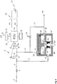
In
Die Parkbremseinrichtung
Weiterhin ist auch ein Vorratseingang
Im Einzelnen ist in der stromlosen Sperrstellung des zweiten 2/2-Wegemagnetventils
Darüber hinaus ist in eine Rückkopplungsleitung
Die beiden 2/2-Wegemagnetventile
Der Arbeitsausgang
Die Steuerleitung
Das Relaisventil
Die Schaltzustände der beiden 2/2-Wegemagnetventile
Das Steuergerät
Im Einzelnen beaufschlagt der Druck pSK in der Steuerkammer
Auf den Relaiskolben
- Aus Richtung Steuerkammer: Fst = pSKASK
- Aus Richtung Arbeitskammer: FAK = FF + pAKAAK
- From the direction of the control chamber: F st = p SK A SK
- From the working chamber: F AK = F F + p AK A AK
Wird die Manschette
Vor diesem Hintergrund ist die Funktionsweise der elektromagnetischen Parkbremssteuereinrichtung
- In dem in
1 gezeigten Grundzustand der elektrischen Parkbremseinrichtung1 sindsowohl das erste 2/2-Wegemagnetventil 10 als auchdas zweite 2/2-Wegemagnetventil 12 unbestromt, so dass überdas Drosselelement 30 der Steuereingang 20 stetsmit dem Arbeitsausgang 28 desRelaisventils 18 verbunden ist. Damit ist die Rückkopplung stabil und es kann keine Druckluft vom Vorratsanschluss2 zum Steuereingang 20 desRelaisventils 18 gelangen bzw. von diesem zur Drucksenke24 entweichen. Damit wird auch der gerade herrschende Druck andem Anschluss 40 für den wenigstens einen Federspeicherbremszylinder und dadurch auch dessen Zuspann- bzw. Lösestellung konstant gehalten.
- In the in
1 shown basic state of the electric parking brake device1 are both the first 2/2-way solenoid valve10th as well as the second 2/2-way solenoid valve12th deenergized so that over the throttle element30th thecontrol input 20 always with thework exit 28 of the relay valve18th connected is. This ensures that the feedback is stable and there is no compressed air from the supply connection2nd to thecontrol input 20 of the relay valve18th get or from this to the pressure sink24th escape. This also applies to the pressure currently prevailing at theconnection 40 for the at least one spring brake cylinder and thereby also the application or release position kept constant.
Soll nun auf ein entsprechendes Feststellbremssignal hin der Druck an dem Anschluss
Wenn dann gilt:
![]()
![]()
![]()
![]()
Soll demgegenüber auf ein entsprechendes Feststellbremssignal hin ein geringerer Druck an dem Anschluss ![]()
![]()
Da während der oben beschriebenen Drucksteuerung bzw. Druckregelung in der Steuerkammer
Zum Herstellen des Betriebszustands „Fahren“ auf ein entsprechendes Feststellbremssignal hin wird das erste 2/2-Wegemagnetventil
Wenn gilt:
![]()
![]()
![]()
![]()
Dadurch wird der Relaiskolben
Da nun die Steuerkammer ![]()
![]()
![]()
![]()
Zum Herstellen des Betriebszustands „Parken“ wird das zweite 2/2-Wegemagnetventil
Wenn gilt:
![]()
![]()
Da die Fläche ASK deutlich größer ist als die Fläche AAK, ist der Druck in der Arbeitskammer
Da wegen der Flächenverhältnisse der Druck pAK in der Arbeitskammer schneller sinkt als der Druck pSK in der Steuerkammer wird Ersterer wegen der Relaiskolbenfeder
Die den Relaiskolben
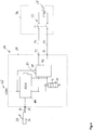
Das elektronische Steuergerät
Darüber hinaus ist eine zweite, von der ersten elektrischen Energieversorgung
Die zweite elektrische Energieversorgung
Bevorzugt ist hier der elektrische Schalter
Beim Schalten des Schalters
In
Gemäß der in
Bei den nachfolgend beschriebenen Ausführungsformen sind gleiche oder gleich wirkende Bauteile und Komponenten mit Bezug auf die voranstehend beschriebene Ausführungsform mit den gleichen Bezugszahlen gekennzeichnet.In the embodiments described below, identical or identically acting parts and components are identified with the same reference numbers with reference to the embodiment described above.
Im Unterschied zu der Ausführungsform von
Bei den Ausführungsformen gemäß
Die elektrische Schalteinrichtung
Bei dieser Alternative stellt daher die elektrische Schalteinrichtung
Die elektrische Schalteinrichtung
Dabei ist die elektrische Schalteinrichtung
Falls jedoch eine der oben genannten Bedingungen nicht erfüllt ist und die am ersten Steueranschluss
Das elektronische Steuergerät
Anstatt zweier Steueranschlüsse
Die elektrische Schalteinrichtung
Andernfalls, also wenn das Signal an dem wenigstens einen elektrischen Steueranschluss
Gemäß der Ausführungsformen von
Die elektrische Schalteinrichtung
Auch bei den Ausführungsformen gemäß
Bei allen Ausführungsformen kann die zweite elektrische Energieversorgung
Bei der Ausführungsform von
Im Unterschied zu der Ausführungsform von
Bei der Ausführungsform von
Die Erfindung umfasst auch jegliche Kombination einer Ausführungsformen gemäß
Auch kann bei einer weiteren, hier nicht gezeigten Ausführungsform, die Rückkopplungsleitung
Generell kann das elektronische Steuergerät
Die Parkbremseinrichtung kann neben den Grundfunktionen „Parken“ und „Fahren“ selbstverständlich weitere Funktionalitäten aufweisen, beispielsweise eine Trailer-Test-Funktion oder eine Hilfsbremsfunktion. Hierzu ist dann die Parkbremseinrichtung und insbesondere die elektromagnetische Ventileinrichtung
BezugszeichenlisteReference list
- 11
- ParkbremseinrichtungParking brake device
- 22nd
- VorratsanschlussSupply connection
- 44th
- Rückschlagventilcheck valve
- 66
- VorratsleitungSupply line
- 88th
- VentileinrichtungValve device
- 1010th
- erstes 2/2-Wegemagnetventilfirst 2/2-way solenoid valve
- 1212th
- zweites 2/2-Wegemagnetventilsecond 2/2-way solenoid valve
- 1414
- SteuergerätControl unit
- 1616
- VorratseingangIncoming goods
- 1818th
- RelaisventilRelay valve
- 2020
- SteuereingangControl input
- 2222
- SteuerleitungControl line
- 2424th
- DrucksenkePressure sink
- 2626
- RückkopplungsleitungFeedback line
- 2828
- ArbeitsausgangWork output
- 3030th
- DrosselelementThrottle element
- 3232
- FeststellbremssignalanschlussParking brake signal connection
- 3434
- SignalleitungSignal line
- 3636
- FeststellbremssignalgeberParking brake signal transmitter
- 3737
- FeststellbremsbetätigungsorganParking brake actuator
- 3838
- ArbeitsleitungWork management
- 4040
- Anschluss für FederspeicherbremszylinderConnection for spring brake cylinder
- 4242
- SteuerkammerTax chamber
- 4444
- Gehäusecasing
- 4646
- RelaiskolbenRelay piston
- 4848
- VentilkörperValve body
- 5050
- AuslasssitzExhaust seat
- 5252
- Manschettecuff
- 5454
- EinlasssitzInlet seat
- 5656
- EntlüftungVenting
- 5858
- ArbeitskammerChamber of Labor
- 6060
- VorratskammerPantry
- 6262
- ManschettenfederCuff spring
- 6464
- RelaiskolbenfederRelay piston spring
- 6666
- erste Energieversorgungfirst energy supply
- 6868
- zweite Energieversorgungsecond energy supply
- 7070
- elektr. Leitungelectr. management
- 7272
- elektr. Schalterelectr. counter
- 7474
- FahrerkabineDriver's cabin
- 7676
- elektr. Schalteinrichtungelectr. Switching device
- 7878
- erster Steueranschlussfirst control connection
- 8080
- zweiter Steueranschlusssecond control connection
- 8282
- Anschlussconnection
- 8484
- BaueinheitUnit
- 8686
- Gehäusecasing
Claims (12)
Priority Applications (5)
| Application Number | Priority Date | Filing Date | Title |
|---|---|---|---|
| DE102015114176.0A DE102015114176C5 (en) | 2015-08-26 | 2015-08-26 | Electric parking brake device with additional energy supply |
| CN201680049432.9A CN107921941B (en) | 2015-08-26 | 2016-08-12 | Electric parking brake device with additional energy supply |
| PCT/EP2016/069201 WO2017032617A1 (en) | 2015-08-26 | 2016-08-12 | Electric parking brake device having an additional energy supply |
| BR112018002645-0A BR112018002645B1 (en) | 2015-08-26 | 2016-08-12 | ELECTRIC PARKING BRAKE DEVICE WITH ADDITIONAL POWER SUPPLY AND VEHICLE WITH A PARKING BRAKE DEVICE |
| EP16750445.5A EP3341253B1 (en) | 2015-08-26 | 2016-08-12 | Electric parking brake with auxiliary power supply |
Applications Claiming Priority (1)
| Application Number | Priority Date | Filing Date | Title |
|---|---|---|---|
| DE102015114176.0A DE102015114176C5 (en) | 2015-08-26 | 2015-08-26 | Electric parking brake device with additional energy supply |
Publications (2)
| Publication Number | Publication Date |
|---|---|
| DE102015114176B3 DE102015114176B3 (en) | 2016-07-21 |
| DE102015114176C5 true DE102015114176C5 (en) | 2020-07-16 |
Family
ID=56293279
Family Applications (1)
| Application Number | Title | Priority Date | Filing Date |
|---|---|---|---|
| DE102015114176.0A Active DE102015114176C5 (en) | 2015-08-26 | 2015-08-26 | Electric parking brake device with additional energy supply |
Country Status (5)
| Country | Link |
|---|---|
| EP (1) | EP3341253B1 (en) |
| CN (1) | CN107921941B (en) |
| BR (1) | BR112018002645B1 (en) |
| DE (1) | DE102015114176C5 (en) |
| WO (1) | WO2017032617A1 (en) |
Families Citing this family (14)
| Publication number | Priority date | Publication date | Assignee | Title |
|---|---|---|---|---|
| DE102017001409A1 (en) | 2017-02-14 | 2018-08-16 | Wabco Gmbh | Method and vehicle control device for an autonomous vehicle and vehicle |
| DE102017208887A1 (en) * | 2017-05-24 | 2018-11-29 | Knorr-Bremse Systeme für Schienenfahrzeuge GmbH | Electropneumatic braking device with safe power supply to realize an emergency braking function |
| US10829101B2 (en) | 2017-11-03 | 2020-11-10 | Continental Automotive Systems, Inc. | Redundant integrated parking brake release circuit |
| DE102018103605A1 (en) * | 2018-02-19 | 2019-08-22 | Knorr-Bremse Systeme für Nutzfahrzeuge GmbH | Electropneumatic equipment of a vehicle |
| DE102018113299A1 (en) * | 2018-06-05 | 2019-12-05 | Wabco Gmbh | An electronic device for controlling an electro-pneumatic parking brake circuit, a parking brake system for a vehicle and a method for controlling an electro-pneumatic parking brake circuit |
| DE102018114642A1 (en) * | 2018-06-19 | 2019-12-19 | Knorr-Bremse Systeme für Nutzfahrzeuge GmbH | Parking brake device for a motor vehicle |
| DE102018120350A1 (en) * | 2018-08-21 | 2020-02-27 | Wabco Gmbh | Electropneumatic parking brake arrangement with shut-off valve |
| DE102018121311A1 (en) | 2018-08-31 | 2020-03-05 | Knorr-Bremse Systeme für Nutzfahrzeuge GmbH | Method, control device and control system for controlling a parking brake system for a vehicle combination with a towing vehicle and a trailer |
| US10780871B2 (en) * | 2018-09-26 | 2020-09-22 | Bendix Commercial Vehicle Systems Llc | Apparatus and method for controlling pneumatic fluid to a trailer |
| DE102018222794A1 (en) * | 2018-12-21 | 2020-06-25 | Audi Ag | Parking brake system |
| DE102019118895A1 (en) * | 2019-07-12 | 2021-01-14 | Knorr-Bremse Systeme für Nutzfahrzeuge GmbH | Parking brake device for a utility vehicle |
| CN110667381A (en) * | 2019-09-27 | 2020-01-10 | 精进电动科技股份有限公司 | Standby power supply system for realizing multiple protection of parking controller |
| DE102020121082A1 (en) | 2020-08-11 | 2022-02-17 | Zf Cv Systems Europe Bv | Secondary braking system of a vehicle and method for its control |
| EP4015322B1 (en) * | 2020-12-17 | 2023-12-06 | KNORR-BREMSE Systeme für Nutzfahrzeuge GmbH | Backup system for an electronic parking brake and a method for providing a backup power |
Citations (7)
| Publication number | Priority date | Publication date | Assignee | Title |
|---|---|---|---|---|
| DE3502100C2 (en) * | 1985-01-23 | 1996-04-11 | Wabco Gmbh | Pressure brake system for motor vehicles |
| DE19758289A1 (en) * | 1997-12-31 | 1999-07-01 | Itt Mfg Enterprises Inc | Electrically operated parking brake for vehicle |
| DE10324809A1 (en) * | 2003-06-02 | 2004-12-23 | Robert Bosch Gmbh | Auxiliary device for releasing the parking brake when there is no power supply |
| DE102011084534A1 (en) * | 2010-10-18 | 2012-04-19 | Continental Teves Ag & Co. Ohg | Fail-safe parking brake for motor vehicles |
| DE102011016740A1 (en) * | 2011-04-12 | 2012-10-18 | Knorr-Bremse Systeme für Nutzfahrzeuge GmbH | Electro-pneumatic parking brake device of a vehicle |
| KR20130009029A (en) * | 2011-07-14 | 2013-01-23 | 현대자동차주식회사 | Electronic parking brake system |
| EP1504975B2 (en) | 2003-08-08 | 2013-10-02 | WABCO GmbH | Brake system for a vehicle using a pressure medium |
Family Cites Families (3)
| Publication number | Priority date | Publication date | Assignee | Title |
|---|---|---|---|---|
| DE102007047692A1 (en) * | 2007-10-05 | 2009-04-09 | Wabco Gmbh | Parking brake modulator and use of a Bremsmodulators as parking brake modulator |
| DE102012010562B4 (en) * | 2012-05-26 | 2013-12-24 | Audi Ag | Parking brake system for a vehicle |
| CN103863293A (en) * | 2013-08-12 | 2014-06-18 | 中国科学院合肥物质科学研究院 | Vehicle parking braking system and control method for same |
-
2015
- 2015-08-26 DE DE102015114176.0A patent/DE102015114176C5/en active Active
-
2016
- 2016-08-12 BR BR112018002645-0A patent/BR112018002645B1/en active IP Right Grant
- 2016-08-12 WO PCT/EP2016/069201 patent/WO2017032617A1/en active Application Filing
- 2016-08-12 EP EP16750445.5A patent/EP3341253B1/en active Active
- 2016-08-12 CN CN201680049432.9A patent/CN107921941B/en active Active
Patent Citations (7)
| Publication number | Priority date | Publication date | Assignee | Title |
|---|---|---|---|---|
| DE3502100C2 (en) * | 1985-01-23 | 1996-04-11 | Wabco Gmbh | Pressure brake system for motor vehicles |
| DE19758289A1 (en) * | 1997-12-31 | 1999-07-01 | Itt Mfg Enterprises Inc | Electrically operated parking brake for vehicle |
| DE10324809A1 (en) * | 2003-06-02 | 2004-12-23 | Robert Bosch Gmbh | Auxiliary device for releasing the parking brake when there is no power supply |
| EP1504975B2 (en) | 2003-08-08 | 2013-10-02 | WABCO GmbH | Brake system for a vehicle using a pressure medium |
| DE102011084534A1 (en) * | 2010-10-18 | 2012-04-19 | Continental Teves Ag & Co. Ohg | Fail-safe parking brake for motor vehicles |
| DE102011016740A1 (en) * | 2011-04-12 | 2012-10-18 | Knorr-Bremse Systeme für Nutzfahrzeuge GmbH | Electro-pneumatic parking brake device of a vehicle |
| KR20130009029A (en) * | 2011-07-14 | 2013-01-23 | 현대자동차주식회사 | Electronic parking brake system |
Also Published As
| Publication number | Publication date |
|---|---|
| BR112018002645A2 (en) | 2018-10-02 |
| BR112018002645B1 (en) | 2023-03-21 |
| EP3341253A1 (en) | 2018-07-04 |
| EP3341253B1 (en) | 2021-07-07 |
| WO2017032617A1 (en) | 2017-03-02 |
| CN107921941B (en) | 2020-11-27 |
| DE102015114176B3 (en) | 2016-07-21 |
| CN107921941A (en) | 2018-04-17 |
Similar Documents
| Publication | Publication Date | Title |
|---|---|---|
| DE102015114176C5 (en) | Electric parking brake device with additional energy supply | |
| DE102015116317B4 (en) | Electro-pneumatic parking brake device of a vehicle with an additional control circuit and towing vehicle with electro-pneumatic parking brake device | |
| EP3129265B1 (en) | Electropneumatic brake controller for controlling a spring brake | |
| EP3678909B1 (en) | Electropneumatic parking brake control device and vehicle brake system | |
| EP3368387B1 (en) | Electro-pneumatic parking brake control system with redundant pneumatic control | |
| EP2384943B1 (en) | Valve device, electrically actuated handbrake and method for controlling same | |
| EP2338753B1 (en) | Electrically actuated handbrake and method for controlling same | |
| EP2939892B1 (en) | Electric parking brake for a vehicle | |
| EP3145769B1 (en) | Electropneumatic brake control device with automatic ventilation of the spring applied brake in the event of a power loss | |
| EP3755589B1 (en) | Electropneumatic equipment of a vehicle | |
| EP3515771B1 (en) | Parking brake device for a utility vehicle | |
| EP3515770B1 (en) | Parking brake valve device for actuating a spring-type parking brake | |
| EP2547565A1 (en) | Electrically actuatable parking brake system | |
| EP2836406B1 (en) | Compressed air system for the air suply of load vehicles | |
| EP2939891B1 (en) | Electric parking brake | |
| EP2675673B1 (en) | Compressed air supply for commerciual vehicle | |
| EP2338754B1 (en) | Electrically actuated handbrake and method for controlling same | |
| EP3112231B1 (en) | Parking brake module, brake system and vehicle using same and method for operating a parking brake having such a module | |
| DE102009016982C5 (en) | Method for operating a braking device of a motor vehicle approaching stops | |
| EP2384944B1 (en) | Method for operating an electrically actuated handbrake | |
| DE202022106835U1 (en) | Electropneumatic parking brake control device |
Legal Events
| Date | Code | Title | Description |
|---|---|---|---|
| R012 | Request for examination validly filed | ||
| R018 | Grant decision by examination section/examining division | ||
| R026 | Opposition filed against patent | ||
| R082 | Change of representative |
Representative=s name: WIEDEMANN, MARKUS, DIPL.-ING.UNIV. DR.-ING., DE |
|
| R034 | Decision of examining division/federal patent court maintaining patent in limited form now final | ||
| R206 | Amended patent specification |