EP3703840B1 - Kontaktloser sensor zur bestimmung von f.o.g. pegel in einem separator mit ultraschall - Google Patents
Kontaktloser sensor zur bestimmung von f.o.g. pegel in einem separator mit ultraschall Download PDFInfo
- Publication number
- EP3703840B1 EP3703840B1 EP18873291.1A EP18873291A EP3703840B1 EP 3703840 B1 EP3703840 B1 EP 3703840B1 EP 18873291 A EP18873291 A EP 18873291A EP 3703840 B1 EP3703840 B1 EP 3703840B1
- Authority
- EP
- European Patent Office
- Prior art keywords
- tank
- sensor
- extension
- static water
- extension collar
- Prior art date
- Legal status (The legal status is an assumption and is not a legal conclusion. Google has not performed a legal analysis and makes no representation as to the accuracy of the status listed.)
- Active
Links
Images


Classifications
-
- E—FIXED CONSTRUCTIONS
- E03—WATER SUPPLY; SEWERAGE
- E03F—SEWERS; CESSPOOLS
- E03F5/00—Sewerage structures
- E03F5/14—Devices for separating liquid or solid substances from sewage, e.g. sand or sludge traps, rakes or grates
- E03F5/16—Devices for separating oil, water or grease from sewage in drains leading to the main sewer
-
- G—PHYSICS
- G01—MEASURING; TESTING
- G01B—MEASURING LENGTH, THICKNESS OR SIMILAR LINEAR DIMENSIONS; MEASURING ANGLES; MEASURING AREAS; MEASURING IRREGULARITIES OF SURFACES OR CONTOURS
- G01B11/00—Measuring arrangements characterised by the use of optical techniques
- G01B11/02—Measuring arrangements characterised by the use of optical techniques for measuring length, width or thickness
- G01B11/06—Measuring arrangements characterised by the use of optical techniques for measuring length, width or thickness for measuring thickness ; e.g. of sheet material
- G01B11/0608—Height gauges
-
- G—PHYSICS
- G01—MEASURING; TESTING
- G01B—MEASURING LENGTH, THICKNESS OR SIMILAR LINEAR DIMENSIONS; MEASURING ANGLES; MEASURING AREAS; MEASURING IRREGULARITIES OF SURFACES OR CONTOURS
- G01B17/00—Measuring arrangements characterised by the use of infrasonic, sonic or ultrasonic vibrations
- G01B17/02—Measuring arrangements characterised by the use of infrasonic, sonic or ultrasonic vibrations for measuring thickness
-
- G—PHYSICS
- G01—MEASURING; TESTING
- G01F—MEASURING VOLUME, VOLUME FLOW, MASS FLOW OR LIQUID LEVEL; METERING BY VOLUME
- G01F23/00—Indicating or measuring liquid level or level of fluent solid material, e.g. indicating in terms of volume or indicating by means of an alarm
- G01F23/22—Indicating or measuring liquid level or level of fluent solid material, e.g. indicating in terms of volume or indicating by means of an alarm by measuring physical variables, other than linear dimensions, pressure or weight, dependent on the level to be measured, e.g. by difference of heat transfer of steam or water
- G01F23/28—Indicating or measuring liquid level or level of fluent solid material, e.g. indicating in terms of volume or indicating by means of an alarm by measuring physical variables, other than linear dimensions, pressure or weight, dependent on the level to be measured, e.g. by difference of heat transfer of steam or water by measuring the variations of parameters of electromagnetic or acoustic waves applied directly to the liquid or fluent solid material
- G01F23/284—Electromagnetic waves
- G01F23/292—Light, e.g. infrared or ultraviolet
- G01F23/2921—Light, e.g. infrared or ultraviolet for discrete levels
- G01F23/2928—Light, e.g. infrared or ultraviolet for discrete levels using light reflected on the material surface
-
- G—PHYSICS
- G01—MEASURING; TESTING
- G01F—MEASURING VOLUME, VOLUME FLOW, MASS FLOW OR LIQUID LEVEL; METERING BY VOLUME
- G01F23/00—Indicating or measuring liquid level or level of fluent solid material, e.g. indicating in terms of volume or indicating by means of an alarm
- G01F23/22—Indicating or measuring liquid level or level of fluent solid material, e.g. indicating in terms of volume or indicating by means of an alarm by measuring physical variables, other than linear dimensions, pressure or weight, dependent on the level to be measured, e.g. by difference of heat transfer of steam or water
- G01F23/28—Indicating or measuring liquid level or level of fluent solid material, e.g. indicating in terms of volume or indicating by means of an alarm by measuring physical variables, other than linear dimensions, pressure or weight, dependent on the level to be measured, e.g. by difference of heat transfer of steam or water by measuring the variations of parameters of electromagnetic or acoustic waves applied directly to the liquid or fluent solid material
- G01F23/296—Acoustic waves
- G01F23/2962—Measuring transit time of reflected waves
-
- C—CHEMISTRY; METALLURGY
- C02—TREATMENT OF WATER, WASTE WATER, SEWAGE, OR SLUDGE
- C02F—TREATMENT OF WATER, WASTE WATER, SEWAGE, OR SLUDGE
- C02F1/00—Treatment of water, waste water, or sewage
- C02F1/40—Devices for separating or removing fatty or oily substances or similar floating material
-
- C—CHEMISTRY; METALLURGY
- C02—TREATMENT OF WATER, WASTE WATER, SEWAGE, OR SLUDGE
- C02F—TREATMENT OF WATER, WASTE WATER, SEWAGE, OR SLUDGE
- C02F2209/00—Controlling or monitoring parameters in water treatment
- C02F2209/02—Temperature
-
- C—CHEMISTRY; METALLURGY
- C02—TREATMENT OF WATER, WASTE WATER, SEWAGE, OR SLUDGE
- C02F—TREATMENT OF WATER, WASTE WATER, SEWAGE, OR SLUDGE
- C02F2209/00—Controlling or monitoring parameters in water treatment
- C02F2209/42—Liquid level
Definitions
- Typical grease traps are either passive grease traps or automatic grease traps (also called a grease separator or interceptor).
- passive traps are the Trapzilla ® line of traps sold by Thermaco, Inc. of Asheboro, N.C. disclosed in U.S. Patent No. 7,367,459 to Batten et al. entitled Passive Grease Trap Using Separator Technology and US Patent No. 7,641,805 to Batten et al. entitled Passive Grease Trap With Pre-Stage For Solids Separation.
- Passive grease traps are usually only emptied of the F.O.G. periodically and therefore F.O.G. tends to build up inside the tank.
- Passive grease traps typically include a tank with an inlet that brings in waste water and an outlet that carries water out of the tank from a low point of the tank. Lightweight F.O.G. rises to the top of the tank and heavier solids settle in the bottom of the tank, a process of stratification. As the amount of F.O.G. that accumulates in the tank becomes excessive, water flushing through the tank can disrupt the F.O.G. that has already separated, causing the F.O.G.
- thermocouples or other temperature sensors in the separator to determine the amount of F.O.G. stored in the separator container, as taught in U.S. Patent 7,828,960 to Batten et al , entitled F.O.G. Separator Control.
- US 2004/0195186 A1 discloses a grease removal system having the features of the preamble of independent claim 1.
- Level sensors mounted to the walls of a separating tank detect the presence of water or grease for grease layer removal.
- DE 19907840 A1 discloses a light liquid separator for separating oil from water, which has a shut-off valve controlled by the level in a separation chamber, and a shut-off valve controlled by the level in a light liquid tank.
- EP 0,329,374 A1 discloses an apparatus for removing floating liquid pollutants from the surface of a body of water, comprising a container for partial immersion in the body of water.
- the present invention fulfills one or more of these needs in the art by providing an apparatus for containing an F.O.G. layer on water including a tank having an inlet and an outlet, as defined in the appended claim 1.
- the inlet is configured to connect to a source of F.O.G.-laden effluent and the outlet is configured to connect to a sewer pipe so that the outlet defines a normal static water level for F.O.G. and effluent in the tank.
- a sensor mounted above the static water level is configured to determine a distance from the sensor to a top of F.O.G. within the tank, so that a thickness of the F.O.G. in the tank can be determined.
- the sensor can be a LIDAR sensor, such as a LIDAR sensor operating at about 940 nm.
- the sensor may be held in place by magnets.
- the tank may have an extension collar above a main body of the tank, with the sensor mounted in the extension collar.
- the extension collar may be generally cylindrical and formed of four arc segments molded of thermoplastic plastic, such as polyethylene.
- the sensor preferably includes a sensor unit mounted in a low part of the extension collar and a battery and electronics unit mounted at a higher part of the extension collar.
- the electronics unit desirably includes a transmitter to transmit a signal indicative of F.O.G. level in the tank.
- the sensor and battery and electronics unit may be linked by a coiled electrical cord and a separate tether having tensile strength sufficient to pull the sensor upwardly through the extension collar for service.
- the tank has a tank top, an extension collar extending upward and supported by the tank top, and an extension top resting on the extension collar.
- the extension top, extension collar and tank top have aligned openings enabling a suction pipe to pass through the aligned openings for suctioning of F.O.G.
- a cover fits on the opening in the extension top to close the aligned openings when suctioning is not needed.
- the invention may also be considered as a method of sensing an F.O.G. level in a tank having an inlet and an outlet, as defined in the appended claim 11, in which the inlet is configured to connect to a source of F.O.G.-laden effluent and the outlet is configured to connect to a sewer pipe so that the outlet defines a normal static water level for F.O.G. and effluent in the tank.
- the method includes sensing a distance from a fixed sensor and a top of F.O.G. above the static water level within the tank and using the sensed distance to determine if the amount of F.O.G in the tank exceeds a threshold warranting F.O.G. removal from the tank.
- F.O.G. removal may include actuating a skimmer.
- F.O.G. removal may include pumping F.O.G. from the tank.
- the sensing may be LIDAR sensing, particularly LIDAR sensing at about 940 nm.
- F.O.G. has a specific gravity of about 0.88 and water has a specific gravity of 1.00, so for every 0.25m (ten inches) of F.O.G. build up in a trap, the F.O.G. displaces 0.22m (8.8 inches) of water while simultaneously projecting upward above the original, normal static water level 0.030m (1.2 inches). Applicant has found that using this known differential property and the known distance from a sensor positioned above the liquid level to the top of the F.O.G. stratum, a determination can be made of how much F.O.G. is in the trap.
- Various sensor technologies can be used, such as laser sensors (popular for golf range finders and a host of industrial uses) and ultrasonic sensors (popular with robotics both industrial and hobbyist applications).
- a suitable ultrasonic sensor is non-contact and non-immersed, looking at sound bounce back to discern the distance to the surface only.
- the ultrasonic sensor can be an electronic module located at the top of the extension collar containing the sensor and cellular electronics. Putting the sensor and cellular electronics in a single module reduces cost and keeps the sensor electronics out of the high temperature and humidity area near the contained F.O.G. and effluent.
- the ultrasonic transducer and temperature probe (such as a thermocouple) may be at the bottom of the extension collar.
- the ultrasonic transducer may be temperature rated to 90C (194 F) and can use a 3 or 4 wire shielded cable, any length.
- the transducer mounting could be normal (downward facing) or rotated 90 degrees (horizontal facing with deflector) depending on the performance needs of the high temperature and humidity environment.
- An ultrasonic signal can be generated horizontally from a transducer that is remote from the source of potentially deleterious heat and humidity and then directed downward to the F.O.G. layer by a deflector.
- the ultrasonic transmitter and receiver can be separate. Since the speed of sound in air varies with temperature, a temperature sensor allows compensation for changes in the time of travel of the ultrasonic signal caused by a temperature variation.
- the ultrasonic signal can be subject to a dynamic gain analysis to discern the F.O.G. from other floating objects.
- Suitable ultrasonic sensors may be available from Senix Corporation, 10516 Route 116, Suite 300, Hinesburg, Vermont 05461 USA.
- Sonar sensors may be used but are not presently preferred because sonar sensors that are waterproof, have a high enough range, and high enough accuracy while taking account the humidity are expensive.
- Computer vision could be another choice: a video sensor aimed at the top surface of the F.O.G. stratum could capture an image, and a computer associated with the electronics unit could compare the image with an image taken of the same scene when the water is at the normal static water level with minimal F.O.G. Computer vision (and/or artificial intelligence) could then detect the height difference by comparing pictures when F.O.G. has accumulated. The less of the inside wall of the trap that the device "sees" means the higher the liquid level inside the tank caused by accumulated F.O.G.
- LIDAR particularly LIDAR operating at about the 940nm wavelength.
- the sensor technology includes the sensor, control board(s), software controls and housing(s). Moisture-resistant properties can be applied to the sensor technology, by way of an enclosing housing or a conformal coating.
- the sensor may be located 300 mm to 1000 mm above the liquid surface, with the distance between the sensor and the liquid surface being filled with air.
- the sensor may be hung/attached onto an expansion collar or on the underside of a top cover (like a manhole cover) of a tank or trap in which the stratification of F.O.G. above the water takes place.
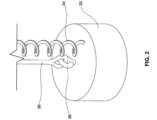
- FIG. 1 shows an embodiment 10 of a separator equipped with the sensor technology.
- a tank 12 has an inlet 14 and outlet (not shown). The height of the outlet usually defines the normal static water level.
- the inlet 14 receives effluent containing F.O.G. (and likely solid kitchen waste).
- the tank 12 has sufficient volume to slow the effluent flow so the less dense F.O.G. has time to rise above the water in the effluent and collects to form a mat within the tank 12.
- the outlet is usually provided with an invert, so that the water exiting the tank 12 comes from the water that is at a low part of the tank, below the accumulated F.O.G. mat.
- the tank 12 may be installed below ground, such as in a parking lot of a restaurant.
- a widened tank top 16 supports a ring-shaped lid 18 and an extension collar 20.
- the collar 20 supports a top ring 22 and a ground-access cover 30.
- Extension collars for underground mounts are further disclosed in U.S. patent 7,540,967 to Batten et al. and U.S. Patent 9,528.258 to McBride et al.
- a tube 26 extends between an electronics unit 28 just below grade and an opening 24 in lid 18.
- the electronics unit 28 contains electronics to analyze data from a sensor in a sensor housing 32 positioned at the bottom of the tube 26 and directed downward into the tank 12.
- the electronics unit 28 may include batteries (or other power supply) and a communication link such as a cell phone connection, WiFi, NFC, Bluetooth or the like, so that information about the the grease mat can be sent to a pumping service to come to pump out the tank.
- Information gleaned from the sensor may be transmitted to a pumper or to a monitoring station using technology as disclosed in International Patent Publication WO 2017/035220 .
- Pumping involves removing the lid 30, extending a suction hose into the tank and pumping the F.O.G. from the tank 12 to a truck that transports the F.O.G. to a rendering plant or other disposal facility. Pumping may also include pumping solids that have accumulated at the bottom of the tank.
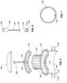
- the sensor housing 32 is seen in Figures 2 and 3 .
- the housing 32 fits within the tube 26, lowered from the top of the tube to rest on a ledge at about the height of the lid 18.
- Ferromagnetic metal fixed in place at the lid 18 and magnets 42A, 42B and 42C on the sensor housing 32 hold the housing in a fixed position at the lid.
- the fixed position sets a reference point for the sensor, so that the distance traversed by the beam of the sensor, such as a Lidar sensor or ultrasonic sensor, can be determined by measuring the round-trip time of flight from the known position of the sensor to the variable height of the top of the F.O.G. mat.
- a Lidar sensor 40 is located in the housing 32, with an attached, coiled data and power cable 34.
- the housing 32 has an attachment 36 and a connected tether 38.
- the tether is strong enough to be pulled upward, enabling the housing 32 to break free of the hold of the magnets and be pulled upward through the tube 26 if servicing is needed.
- the sensor 40 directs a pulse downward into the tank 12, and the pulse is reflected by F.O.G. within the tank.
- the time interval between the sensor's sending of the pulse and the sensor's receipt of the reflected pulse is proportional to the distance from the sensor to the top of the F.O.G. mat. Data indicative of that time interval is sent to the electronics unit 28 for analysis.
- the analysis of Lidar data can include subtracting the time of flight when the tank has zero F.O.G. mat (which can be a stored value) from the measured time of flight. If the result exceeds a threshold that is characteristic of the tank, the data indicates that the F.O.G. mat is thick enough that pumping is warranted, so a signal can be sent to the pumping service to come pump the tank. If the data indicates that the mat thickness is too large, an urgency alarm can be added to the signal to the pumping service. Also within the scope of the invention is for the electronics unit to send a signal that pumping is not needed if the F.O.G. mat is determined not to be thick enough to warrant pumping. Similar analysis can be used with an ultrasonic sensor.
- the sensing of the F.O.G. thickness can be repeated continually, to provide continual monitoring of when pumping or other removal is needed.
- a schedule of sensing the thickness may be once a day, once a week or some other schedule, depending on the needs of the installation.
- the sensing can be triggered by a signal from a remote communication source, or by a timer or other mechanism internal to the electronics unit 28.
- FIGs 4-7 show an alternate embodiment, differing in the construction of the extension collar and the tube configuration for the sensor housing.
- the lower part of the tank 112 is omitted.
- the tank 112 has an inlet 114 and outlet (not shown).
- the inlet receives effluent containing F.O.G. (and likely solid kitchen waste)
- the tank 112 has sufficient volume to slow the effluent flow so the lower- density F.O.G. rises above the water in the effluent and collects to form a mat within the tank 112.
- the outlet is usually provided with an invert, so that the water exiting the tank 112 is from the water at a low part of the tank, below the accumulated mat.
- the tank 112 may be installed below ground, such as in a parking lot of a restaurant.
- a widened tank top 116 supports a ring-shaped lid 118 and an extension collar made of arc segments 120 and 121.
- the collar supports a top ring 122 and a ground-access cover 130.
- the extension collar is made up of four extruded sections (arcs) that interlock together to form a generally cylindrical shape with vertical flutings or corrugations.
- the extruded sections are knocked down for shipping and field assembled to create a cylinder.
- the collar includes three identical arcs 120 and a fourth arc 121.
- the arc 121 differs from the three arcs 120 in that it has the tube 126 for the sensor assembly.
- the edges of adjacent arcs join one another with an interlock like a tongue and groove construction.
- the tube 126 can also tie the pieces above and below it together for alignment of the tube. After assembly of the arcs, the collar is cut to length. The desired length will be specific for an installation, but will be sufficient to extend from the top surface of the lid 118 to a height to receive a top ring 122 that supports a cover 130, typically ground level.
- the cover 130 can be bolted into place on the top ring so it is removable for F.O.G. pumping or servicing of the sensor unit.
- the tube 126 has a stainless steel or other ferromagnetic metal ring 143 (see Figure 5 ) below its bottom and secured to the tank top 118 for magnetic attraction to magnets 142 in the sensor housing 132.
- the housing 132 has a coiled data and power cable 134 extending to a cylindrical electronics unit 128.
- a ring 129 on the housing 132 causes it to rest at a desired height in the tube 126, typically on the top ring 122 with the portion of the electronics unit above the ring 129 being short enough that it can be covered and protected by the cove 130.
- An antenna for cell phone connection, WiFi, NFC, Bluetooth or the like is positioned at the top of electronics unit 128, the top of which itself nests within a space 131 formed in the top ring 122.
- the Lidar unit (sensor and electronics unit) can be shipped with the unit when it is new or retrofitted at a later date. Once the top cover 130 is removed, the top of the Lidar unit can be pulled out of its tube 126 for servicing, such as to replace batteries. A cable or other line like the tether 38 of the embodiment of Figure 1 can be used to pull the sensor up the tube 126. To install Lidar in a unit that is not equipped with it, the top cover is removed and the tube is exposed. The sensor housing 132 is lowered into the tube 126 and is held in place onto the stainless washer 143 by the magnets 142 at the bottom of the tube 126.
- Lidar sensors with wavelengths in the mid to far IR range have been found not to be suitable because oil absorbs radiation at those wavelengths.
- a preferred LIDAR sensor operates at 940nm for the VL53L0X Lidar chip.
- the VL53L0X is a new generation Time-of-Flight (ToF) laser-ranging module. It can measure absolute distances up to 2m.
- Another usable chip is the VL53L1, which is a Time-of-Flight (ToF) laser-ranging miniature sensor. This chip integrates a SPAD (Single Photon Avalanche Diodes) array, physical infrared filters and optics. Both sensors are available from STMicroelectronics NV of Geneva, Switzerland (st.com).
- SPAD Single Photon Avalanche Diodes
- Both sensors are available from STMicroelectronics NV of Geneva, Switzerland (st.com).
- the VL53L0x does not accurately read a water level, but that is immaterial because the only time there will not be at least a film of oil on the surface of the liquid in the trap is when the unit is first installed.
- the use of a converter circuit may be needed to convert the I2C signal to another digital signal with a longer communications range.
- the VL53L0x chip Since the VL53L0x chip has a very short range when dealing with oils, it is preferably mounted at about 0.25m (10 inches) from the static water level. Mounting the sensor and its electronics in a tube separate from the main central opening of the trap reduces the risk that a pumper's suction equipment could collide with it.
- An ultrasonic transducer and temperature probe (such as a thermocouple) may be at the bottom of the extension collar.
- the ultrasonic transducer may be temperature rated to 90C (194 F) and can use a 3 or 4 wire shielded cable, any length.
- the transducer mounting could be normal (downward facing) or rotated 90 degrees (horizontal facing with deflector) depending on the performance needs of the high temperature and humidity environment.
- An ultrasonic signal can be generated horizontally from a transducer that is remote from the source of potentially deleterious heat and humidity and then directed downward to the F.O.G. layer by a deflector.
- the ultrasonic transmitter and receiver can be separate.
- a temperature sensor can be used to allow compensation for changes in the time of travel of the ultrasonic signal caused by temperature variations.
- the ultrasonic signal can be subject to a dynamic gain analysis to discern the F.O.G. from other floating objects.
- Suitable ultrasonic sensors may be available from Senix Corporation, 10516 Route 116, Suite 300, Hinesburg, Vermont 05461 USA.
- skimming includes other ways of taking the F.O.G. off the top, including opening spouts that drain the F.O.G. (see U.S. Patent 7,186,346 for examples), pumping the F.O.G. (see U.S. Patent 6,517,715 for an example), or other active methods. More examples and details of a F.O.G. removal assembly may be found in U.S. Patent No. 6,800,195 to Batten et al. and U.S.
- Patent No. 7,208,080 to Batten et al. Other types of skimmers can be used in the invention, too, including but not limited to: belt skimmers, examples of which can be seen in U.S. Patent 7,427,356 to Chapin and 7,296,694 to Weymouth ; skimmers that include one or more rotating cylinders that partially or completely submerge, one example as is shown in U.S. Pat. No. 4,051,024 to Lowe et al ; skimmers with an absorptive affinity for F.O.G and/or skimmers that include non-cylindrical grease collectors pivoting to come into contact with F.O.G. for removal, one example as seen in U.S. Patent 4,235,726 to Shimko .
- the tank and its attachments preferably have an International Protection Rating of IP 65.
- the sensor can also be installed in conventional concrete grease traps.
- An added feature can include a data analysis module associated with the electronics unit to deal with deviations from normal static water levels.
- the data analysis can include distinguishing levels of normal flow events from levels created from downstream full or partial plumbing obstructions. These two events, like accumulations of F.O.G., result in sensor readings that are higher than the normal static water level (which is usually determined by the height of the outlet from the trap). Rising levels that are due to normal flow events are transitory and can be distinguished by taking several readings over a period of time and disregarding those that show a high level that soon returns to the normal level.
Landscapes
- Physics & Mathematics (AREA)
- Electromagnetism (AREA)
- General Physics & Mathematics (AREA)
- Thermal Sciences (AREA)
- Fluid Mechanics (AREA)
- Health & Medical Sciences (AREA)
- Acoustics & Sound (AREA)
- Life Sciences & Earth Sciences (AREA)
- Engineering & Computer Science (AREA)
- Hydrology & Water Resources (AREA)
- Public Health (AREA)
- Water Supply & Treatment (AREA)
- Measurement Of Levels Of Liquids Or Fluent Solid Materials (AREA)
- Measurement Of Velocity Or Position Using Acoustic Or Ultrasonic Waves (AREA)
- Optical Radar Systems And Details Thereof (AREA)
Claims (15)
- Vorrichtung zum Aufnehmen einer FOG-Schicht auf Wasser, die Folgendes umfasst:einen Tank (12, 112) mit einem Einlass (14, 114) und einem Auslass, wobei der Einlass (14, 114) zum Verbinden mit einer Quelle von mit FOG beladenem Abwasser konfiguriert ist und der Auslass zum Verbinden mit einem Abwasserrohr konfiguriert ist, so dass der Auslass einen normalen statischen Wasserstand für FOG und Abwasser im Tank (12, 112) definiert, so dass die Oberseite der FOG-Schicht über den normalen statischen Wasserstand ansteigt, weil eine spezifische Dichte von FOG geringer ist als die spezifische Dichte von Wasser, unddadurch gekennzeichnet, dass ein Sensor (40) über dem normalen statischen Wasserstand montiert und zum Bestimmen eines Abstands vom Sensor (40) über der Oberseite der FOG-Schicht bis zur Oberseite der FOG-Schicht innerhalb des Tanks (12, 112) konfiguriert ist, so dass eine Dicke der FOG-Schicht im Tank (12, 112) bestimmt werden kann, indem ausgewertet wird, wie weit die Oberseite der FOG-Schicht über dem normalen statischen Wasserstand liegt.
- Vorrichtung nach Anspruch 1, wobei der Sensor (40) ein LIDAR-Sensor (40) ist, der optional bei etwa 940 nm arbeitet.
- Vorrichtung nach Anspruch 1, wobei der Sensor (40) durch Magnete (42A, 42B, 42C, 142) festgehalten wird.
- Vorrichtung nach Anspruch 1, wobei der Tank (12, 112) einen Verlängerungskragen (20) über einem Hauptkörper des Tanks (12, 112) aufweist und der Sensor (40) in dem Verlängerungskragen (20) montiert ist.
- Vorrichtung nach Anspruch 4, wobei der Verlängerungskragen (20) allgemein zylindrisch und aus aus rotationsgeformtem Kunststoff geformten Bogensegmenten (120, 121) gebildet ist.
- Vorrichtung nach Anspruch 4, wobei der Sensor (40) eine in einem unteren Teil des Verlängerungskragens (20) montierte Sensoreinheit und eine an einem höheren Teil des Verlängerungskragens (20) montierte Batterie- und Elektronikeinheit (28) umfasst, und wobei die Elektronikeinheit (28) einen Sender umfasst, um ein Signal zu senden, das den FOG-Stand im Tank (12, 112) anzeigt.
- Vorrichtung nach Anspruch 6, wobei der Sensor (40) und die Batterie- und Elektronikeinheit (28) durch ein gewendeltes elektrisches Kabel verbunden sind und sich eine Anbindung (38) mit einer Zugfestigkeit, die zum Ziehen des Sensors (40) zur Wartung nach oben durch den Verlängerungskragen (20) ausreicht, den Verlängerungskragen (20) hinauf erstreckt.
- Vorrichtung nach Anspruch 1, wobei der Tank (12, 112) eine Tankoberseite, einen sich nach oben erstreckenden und von der Tankoberseite getragenen Verlängerungskragen (20) und eine auf dem Verlängerungskragen (20) aufliegende Verlängerungsoberseite aufweist,wobei die Verlängerungsoberseite, der Verlängerungskragen (20) und die Tankoberseite fluchtende Öffnungen aufweisen, durch die ein Saugrohr zum Absaugen von FOG passieren kann, undwobei eine Abdeckung (30, 130) auf die Öffnung in der Oberseite der Verlängerung passt, um die fluchtenden Öffnungen zu verschließen, wenn kein Absaugen erforderlich ist.
- Vorrichtung nach Anspruch 1, wobei der Sensor (40) mit Computervision arbeitet oder ein Ultraschallsensor (40) ist.
- Vorrichtung nach Anspruch 1, die eine Elektronikeinheit und ein Datenanalysemodul umfasst, das mit der Elektronikeinheit assoziiert und zum Behandeln von Abweichungen von normalen statischen Wasserständen konfiguriert ist.
- Verfahren zum Erfassen eines FOG-Stands in einem Tank (12, 112) mit einem Einlass (14, 114) und einem Auslass, wobei der Einlass (14, 114) zum Verbinden mit einer Quelle von mit FOG beladenem Abwasser konfiguriert ist und der Auslass zum Verbinden mit einem Abwasserrohr konfiguriert ist, so dass der Auslass einen normalen statischen Wasserstand für FOG und Abwasser im Tank (12, 112) definiert,
dadurch gekennzeichnet, dass ein Abstand zwischen einem an einer Position über einer Oberseite der FOG-Schicht befestigten Sensor (40) und der Oberseite der FOG-Schicht erfasst wird, wobei die Oberseite der FOG-Schicht über dem normalen statischen Wasserstand innerhalb des Tanks (12, 112) liegt und der erfasste Abstand verwendet wird zum Bestimmen, ob die Menge an FOG im Tank (12, 112) einen Schwellenwert überschreitet, der das Entfernen von FOG aus dem Tank (12, 112) rechtfertigt. - Verfahren nach Anspruch 11, wobei das Entfernen von FOG das Betätigen eines Skimmers oder das Abpumpen von FOG aus dem Tank (12, 112) beinhaltet.
- Verfahren nach Anspruch 11, wobei das Erfassen eine LIDAR-Erfassung ist, optional bei etwa 940 nm.
- Verfahren nach Anspruch 11, das ferner das Analysieren von Daten über den Abstand zwischen dem Sensor (40) und dem normalen statischen Wasserstand beinhaltet, um Abweichungen von normalen statischen Wasserständen zu handhaben.
- Verfahren nach Anspruch 11, wobei die Erfassung Computervision-Erfassung oder Ultraschallerfassung ist.
Applications Claiming Priority (3)
| Application Number | Priority Date | Filing Date | Title |
|---|---|---|---|
| US201762579430P | 2017-10-31 | 2017-10-31 | |
| US201762608921P | 2017-12-21 | 2017-12-21 | |
| PCT/US2018/058346 WO2019089686A1 (en) | 2017-10-31 | 2018-10-31 | Non-contact sensor for determining a f.o.g. level in a separator, including ultrasonics |
Publications (4)
| Publication Number | Publication Date |
|---|---|
| EP3703840A1 EP3703840A1 (de) | 2020-09-09 |
| EP3703840A4 EP3703840A4 (de) | 2021-08-11 |
| EP3703840B1 true EP3703840B1 (de) | 2025-02-12 |
| EP3703840C0 EP3703840C0 (de) | 2025-02-12 |
Family
ID=66333382
Family Applications (1)
| Application Number | Title | Priority Date | Filing Date |
|---|---|---|---|
| EP18873291.1A Active EP3703840B1 (de) | 2017-10-31 | 2018-10-31 | Kontaktloser sensor zur bestimmung von f.o.g. pegel in einem separator mit ultraschall |
Country Status (8)
| Country | Link |
|---|---|
| US (2) | US11708691B2 (de) |
| EP (1) | EP3703840B1 (de) |
| JP (1) | JP2021501346A (de) |
| AU (1) | AU2018360590B2 (de) |
| CA (1) | CA3080475A1 (de) |
| ES (1) | ES3021202T3 (de) |
| SG (1) | SG11202003826UA (de) |
| WO (1) | WO2019089686A1 (de) |
Families Citing this family (4)
| Publication number | Priority date | Publication date | Assignee | Title |
|---|---|---|---|---|
| WO2020160357A1 (en) * | 2019-02-01 | 2020-08-06 | Thermaco, Incorporated | Multilayer rotomolded grease trap |
| US12031934B2 (en) | 2019-06-28 | 2024-07-09 | Thermaco Incorporated | Fog sensor for tailpipes |
| US11267726B1 (en) | 2020-03-09 | 2022-03-08 | Thermaco, Incorporated | Grease trap with safety barrier |
| CN112057921A (zh) * | 2020-08-26 | 2020-12-11 | 浙江西菱股份有限公司 | 一种餐厨垃圾处理器用过滤机构 |
Citations (2)
| Publication number | Priority date | Publication date | Assignee | Title |
|---|---|---|---|---|
| US6423213B1 (en) * | 2000-07-28 | 2002-07-23 | Josam Company | Continuous level measurement for grease separator |
| US20040195186A1 (en) * | 2003-03-25 | 2004-10-07 | Zurn Industries, Inc. | Grease removal system |
Family Cites Families (62)
| Publication number | Priority date | Publication date | Assignee | Title |
|---|---|---|---|---|
| US978889A (en) | 1910-02-19 | 1910-12-20 | Karl Imhoff | Treating sewage. |
| US1200951A (en) | 1916-01-19 | 1916-10-10 | Kelly Separator Company | Separator. |
| US1760229A (en) | 1929-08-28 | 1930-05-27 | Arndt Charles | Separator to clarify waste waters |
| US2226968A (en) | 1937-12-06 | 1940-12-31 | Clerici Carlo | Basin for clarifying and cleansing dirty and drain waters |
| US2213458A (en) | 1938-09-02 | 1940-09-03 | J W Swanson | Septic tank |
| US2338971A (en) | 1942-04-27 | 1944-01-11 | Illinois Iron & Bolt Company | Grease separator |
| US2846073A (en) * | 1955-11-22 | 1958-08-05 | Sr Kermit Dwight Hopper | Liquid separation decanter |
| US3025962A (en) | 1958-09-02 | 1962-03-20 | Sanitary Plastics Inc | Protective devices for septic tanks |
| US3048277A (en) | 1959-03-10 | 1962-08-07 | Marshall R Bland | Grid for dirt trap sump |
| US3224593A (en) | 1961-05-23 | 1965-12-21 | Nebolsine Ross | Apparatus for separation of oil from aqueous mixtures |
| US3433385A (en) | 1967-09-05 | 1969-03-18 | Joseph Emile Metivier | Bayonet closure for container |
| US3662918A (en) | 1970-08-24 | 1972-05-16 | David D Crawford | Reinforced septic tank |
| US3761929A (en) | 1971-02-24 | 1973-09-25 | Us Navy | Radar spoof |
| US3923655A (en) | 1974-12-09 | 1975-12-02 | Vesmat Investments | Level detection system |
| US4038186A (en) | 1975-10-14 | 1977-07-26 | Texaco Inc. | Carbon decanter |
| US4051024A (en) | 1976-01-29 | 1977-09-27 | Lowe Engineering Company | Oil recovery apparatus and method |
| US4113617A (en) * | 1977-04-21 | 1978-09-12 | Fred Phillip Bereskin | Grease separator |
| US4235726A (en) | 1979-03-12 | 1980-11-25 | Baker-Waldeck Associates | Automatic grease separating apparatus |
| US4268392A (en) | 1979-06-01 | 1981-05-19 | Tiger Manufacturing Company | Disposable plastic trap bag |
| HU181642B (en) | 1979-12-12 | 1983-10-28 | Arvizvedelmi Es Belvizvedelmi | Method and device for removing floating liquid contaminations particularly oil ones |
| FR2480617B1 (fr) | 1980-04-21 | 1986-01-17 | Bardet Sa Ets Andre | Appareil et installation de separation de liquides non miscibles de densites differentes |
| US4385986A (en) | 1981-04-08 | 1983-05-31 | Nelson Industries, Inc. | Gravity separator for separating liquids |
| US4832711A (en) | 1982-02-25 | 1989-05-23 | Pall Corporation | Adsorbent fractionator with automatic temperature-sensing cycle control and process |
| US4722800A (en) * | 1986-05-30 | 1988-02-02 | Highland Tank And Manufacturing Company | Oil-water separator |
| GB8803822D0 (en) | 1988-02-18 | 1988-03-16 | Hoyle Marine Ltd | Apparatus for removing floating liquid pollutants from surface of water & control system therefor |
| US4807201A (en) * | 1988-03-25 | 1989-02-21 | Illinois State University | Groundwater pressure measurement |
| US4972709A (en) | 1988-10-03 | 1990-11-27 | Bailey Jr James R | Pump control system, level sensor switch and switch housing |
| US5021153A (en) | 1989-11-20 | 1991-06-04 | G-H Systems, Inc. | Combined apparatus for removing grit and grease from sewage |
| US5492619A (en) | 1994-04-12 | 1996-02-20 | Clearline Systems, Inc. | Automatic grease collection system |
| US5705055A (en) | 1995-06-23 | 1998-01-06 | Josam Company | Apparatus for automatically recovering grease from a grease separator |
| US5946967A (en) | 1996-06-07 | 1999-09-07 | Worldstone, Inc. | Automatic monitoring system for a separation reservoir |
| US6014076A (en) | 1996-12-31 | 2000-01-11 | Global Tech, Inc. | Apparatus and method for achieving intrinsic safety using conventional sensors |
| US6108212A (en) | 1998-06-05 | 2000-08-22 | Motorola, Inc. | Surface-mount device package having an integral passive component |
| US6251286B1 (en) | 1998-07-22 | 2001-06-26 | Douglas Engineering Div.U.S. Hydrex Inc. | Accumulating automatic skimmer |
| DE19907840A1 (de) | 1999-02-24 | 2000-08-31 | Awas Heinz Ihne | Leichtflüssigkeitsabscheider mit Ablaufsperre |
| US6776900B2 (en) | 2000-07-28 | 2004-08-17 | Josam Company | Level measurement for grease separators |
| CA2396689A1 (en) * | 2001-08-03 | 2003-02-03 | Steel Tank Institute | Oil-water separator |
| US6879935B2 (en) | 2002-04-25 | 2005-04-12 | Sepsensor Inc. | Monitoring system with thermal probe for detection of layers in stratified media |
| US6619118B1 (en) | 2002-04-25 | 2003-09-16 | Sepsensor Inc. | Monitoring system |
| DE10220126B4 (de) * | 2002-05-06 | 2008-01-03 | Siemens Ag | Vorrichtung zur Befestigung von Initiatoren und Sensoren |
| US6979403B2 (en) | 2002-08-28 | 2005-12-27 | Nancy Jeannine Rodis | Grease interceptor (trap) and servicing method |
| US7144506B2 (en) | 2004-02-18 | 2006-12-05 | Fralo Plastech Mfg., Llc | Blow molded septic tank and method of manufacture |
| US7297284B2 (en) | 2004-03-26 | 2007-11-20 | Goslyn, L.P. | Separator for immiscible liquids |
| US7360417B2 (en) | 2005-01-10 | 2008-04-22 | Gems Sensors, Inc. | Fluid level detector |
| EP1816107B1 (de) * | 2006-02-06 | 2010-04-21 | Hach Lange GmbH | Abwasser-Sedimentationsanlage |
| US7607347B2 (en) | 2006-03-07 | 2009-10-27 | Gems Sensors, Inc. | Fluid level detector |
| US7367459B2 (en) | 2006-04-27 | 2008-05-06 | Thermaco, Inc. | Passive grease trap using separator technology |
| US7828960B1 (en) | 2007-05-16 | 2010-11-09 | Thermaco, Inc. | F.O.G. separator control |
| EP2037233A1 (de) | 2007-09-14 | 2009-03-18 | General Electric Company | Fluiddetektor |
| US20090220380A1 (en) * | 2008-03-01 | 2009-09-03 | Daniel Joel Brown | Wireless electronic monitor for a container such as an aquarium and the like |
| US7635854B1 (en) * | 2008-07-09 | 2009-12-22 | Institut National D'optique | Method and apparatus for optical level sensing of agitated fluid surfaces |
| US20100315654A1 (en) * | 2009-06-11 | 2010-12-16 | Marcia Jada Berger | LIDAR Instrument System and Process |
| US20120281096A1 (en) * | 2011-05-02 | 2012-11-08 | Honeywell-Enraf B.V. | Storage tank inspection system and method |
| SE537416C2 (sv) * | 2012-11-01 | 2015-04-21 | Janis Platbardis | System och förfarande för att mäta och rapportera vätskenivåi olje-, och fettavskiljare. |
| US9140786B2 (en) * | 2012-12-07 | 2015-09-22 | Harris Corporation | Method and system using radiometric volumetric data for detecting oil covered by ice |
| TWI473976B (zh) | 2013-06-28 | 2015-02-21 | Univ Nat Taiwan Ocean | 液面高度量測模組 |
| US20150308094A1 (en) | 2014-02-21 | 2015-10-29 | Thermaco, Inc. | System and control for grease removal |
| US20160122209A1 (en) * | 2014-10-30 | 2016-05-05 | Edward G. Newman, JR. | Selective fluid retrieval and treatment system for oil and wastewater recovery |
| KR20170104571A (ko) * | 2015-01-16 | 2017-09-15 | 베이직 워터 솔루션즈, 엘엘씨 | 수질 조정용 시스템 및 방법 |
| CA2903838C (en) * | 2015-09-10 | 2022-08-23 | Canplas Industries Ltd. | Waste water separation vessel |
| US20170082478A1 (en) | 2015-09-22 | 2017-03-23 | Gems Sensors, Inc. | System and method of ultrasound liquid level detection |
| GB2547044B (en) * | 2016-02-08 | 2019-02-06 | Fourphase As | Oil, water, gas and solid particle separation in oil and/or gas production |
-
2018
- 2018-10-31 ES ES18873291T patent/ES3021202T3/es active Active
- 2018-10-31 WO PCT/US2018/058346 patent/WO2019089686A1/en not_active Ceased
- 2018-10-31 SG SG11202003826UA patent/SG11202003826UA/en unknown
- 2018-10-31 CA CA3080475A patent/CA3080475A1/en active Pending
- 2018-10-31 EP EP18873291.1A patent/EP3703840B1/de active Active
- 2018-10-31 AU AU2018360590A patent/AU2018360590B2/en active Active
- 2018-10-31 JP JP2020544338A patent/JP2021501346A/ja active Pending
- 2018-10-31 US US16/753,498 patent/US11708691B2/en active Active
-
2023
- 2023-05-12 US US18/196,753 patent/US20230279655A1/en active Pending
Patent Citations (2)
| Publication number | Priority date | Publication date | Assignee | Title |
|---|---|---|---|---|
| US6423213B1 (en) * | 2000-07-28 | 2002-07-23 | Josam Company | Continuous level measurement for grease separator |
| US20040195186A1 (en) * | 2003-03-25 | 2004-10-07 | Zurn Industries, Inc. | Grease removal system |
Also Published As
| Publication number | Publication date |
|---|---|
| SG11202003826UA (en) | 2020-05-28 |
| ES3021202T3 (en) | 2025-05-26 |
| AU2018360590B2 (en) | 2024-03-28 |
| US20230279655A1 (en) | 2023-09-07 |
| US20210164215A1 (en) | 2021-06-03 |
| US11708691B2 (en) | 2023-07-25 |
| AU2018360590A1 (en) | 2020-05-21 |
| JP2021501346A (ja) | 2021-01-14 |
| WO2019089686A1 (en) | 2019-05-09 |
| CA3080475A1 (en) | 2019-05-09 |
| EP3703840A1 (de) | 2020-09-09 |
| EP3703840C0 (de) | 2025-02-12 |
| EP3703840A4 (de) | 2021-08-11 |
Similar Documents
| Publication | Publication Date | Title |
|---|---|---|
| US20230279655A1 (en) | Non-contact sensor for determining a f.o.g. level in a separator using rotomolded parts | |
| EP2010301B1 (de) | Passives fettfilter mit abscheidertechnologie, verfahren deren herstellung und verwendung | |
| US12252416B2 (en) | Control of grease removal equipment via cell phone app | |
| KR101772984B1 (ko) | 부유물 제거장치 | |
| CN107318825B (zh) | 毒饵盒和用于分离投放点的方法 | |
| KR102026340B1 (ko) | 거름관을 이용한 부표식 레이저 수위계 | |
| RU2722862C1 (ru) | Способ автоматизированного беспроводного мониторинга уровня жидкости и устройство для его осуществления | |
| KR101689606B1 (ko) | 불감대가 제거된 개수로 유량측정시스템 및 그 제어방법 | |
| KR102026339B1 (ko) | 부표식 레이저 수위계 | |
| CA2907786A1 (en) | Self-calibrating ultrasonic-based monitoring system | |
| WO2007103418A2 (en) | Early detection and advanced warning 'waste is backing up' apparatus and method | |
| WO2017119324A1 (ja) | センサの収容装置 | |
| KR101825168B1 (ko) | 오폐수의 정화처리장치 | |
| WO2007124297A1 (en) | Stormwater treatment system with automated contaminant buildup detection | |
| JP2019066358A (ja) | 水位計測装置 | |
| JP2003082752A (ja) | 異常検知機能付き阻集器および阻集器の異常検知方法 | |
| DK176679B1 (da) | Sensor til detektering af slamniveau | |
| US11267726B1 (en) | Grease trap with safety barrier | |
| KR101400915B1 (ko) | 우수처리장치 | |
| CA3087449C (en) | Instantaneous water/oil separation system | |
| EP4553245A1 (de) | Ultraschallüberwachung von füllständen in entwässerungselementen | |
| US20100079293A1 (en) | Device for detecting a body falling into a pool | |
| EP3040489A1 (de) | Vorrichtung zur entleerung einer flüssigkeit aus einem behälter, und entsprechendes detektionsmodul | |
| GB2592907A (en) | A Silt Detector |
Legal Events
| Date | Code | Title | Description |
|---|---|---|---|
| STAA | Information on the status of an ep patent application or granted ep patent |
Free format text: STATUS: THE INTERNATIONAL PUBLICATION HAS BEEN MADE |
|
| PUAI | Public reference made under article 153(3) epc to a published international application that has entered the european phase |
Free format text: ORIGINAL CODE: 0009012 |
|
| STAA | Information on the status of an ep patent application or granted ep patent |
Free format text: STATUS: REQUEST FOR EXAMINATION WAS MADE |
|
| 17P | Request for examination filed |
Effective date: 20200512 |
|
| AK | Designated contracting states |
Kind code of ref document: A1 Designated state(s): AL AT BE BG CH CY CZ DE DK EE ES FI FR GB GR HR HU IE IS IT LI LT LU LV MC MK MT NL NO PL PT RO RS SE SI SK SM TR |
|
| AX | Request for extension of the european patent |
Extension state: BA ME |
|
| DAV | Request for validation of the european patent (deleted) | ||
| DAX | Request for extension of the european patent (deleted) | ||
| A4 | Supplementary search report drawn up and despatched |
Effective date: 20210713 |
|
| RIC1 | Information provided on ipc code assigned before grant |
Ipc: B01D 17/032 20060101AFI20210707BHEP Ipc: B01D 35/02 20060101ALI20210707BHEP Ipc: C02F 1/40 20060101ALI20210707BHEP Ipc: E03F 5/14 20060101ALI20210707BHEP Ipc: G01B 15/02 20060101ALI20210707BHEP |
|
| STAA | Information on the status of an ep patent application or granted ep patent |
Free format text: STATUS: EXAMINATION IS IN PROGRESS |
|
| 17Q | First examination report despatched |
Effective date: 20240125 |
|
| GRAP | Despatch of communication of intention to grant a patent |
Free format text: ORIGINAL CODE: EPIDOSNIGR1 |
|
| STAA | Information on the status of an ep patent application or granted ep patent |
Free format text: STATUS: GRANT OF PATENT IS INTENDED |
|
| GRAJ | Information related to disapproval of communication of intention to grant by the applicant or resumption of examination proceedings by the epo deleted |
Free format text: ORIGINAL CODE: EPIDOSDIGR1 |
|
| STAA | Information on the status of an ep patent application or granted ep patent |
Free format text: STATUS: EXAMINATION IS IN PROGRESS |
|
| INTG | Intention to grant announced |
Effective date: 20240814 |
|
| GRAP | Despatch of communication of intention to grant a patent |
Free format text: ORIGINAL CODE: EPIDOSNIGR1 |
|
| STAA | Information on the status of an ep patent application or granted ep patent |
Free format text: STATUS: GRANT OF PATENT IS INTENDED |
|
| INTC | Intention to grant announced (deleted) | ||
| INTG | Intention to grant announced |
Effective date: 20240924 |
|
| GRAS | Grant fee paid |
Free format text: ORIGINAL CODE: EPIDOSNIGR3 |
|
| GRAA | (expected) grant |
Free format text: ORIGINAL CODE: 0009210 |
|
| STAA | Information on the status of an ep patent application or granted ep patent |
Free format text: STATUS: THE PATENT HAS BEEN GRANTED |
|
| AK | Designated contracting states |
Kind code of ref document: B1 Designated state(s): AL AT BE BG CH CY CZ DE DK EE ES FI FR GB GR HR HU IE IS IT LI LT LU LV MC MK MT NL NO PL PT RO RS SE SI SK SM TR |
|
| REG | Reference to a national code |
Ref country code: GB Ref legal event code: FG4D |
|
| REG | Reference to a national code |
Ref country code: CH Ref legal event code: EP |
|
| REG | Reference to a national code |
Ref country code: DE Ref legal event code: R096 Ref document number: 602018079170 Country of ref document: DE |
|
| REG | Reference to a national code |
Ref country code: IE Ref legal event code: FG4D |
|
| U01 | Request for unitary effect filed |
Effective date: 20250303 |
|
| U07 | Unitary effect registered |
Designated state(s): AT BE BG DE DK EE FI FR IT LT LU LV MT NL PT RO SE SI Effective date: 20250327 |
|
| REG | Reference to a national code |
Ref country code: ES Ref legal event code: FG2A Ref document number: 3021202 Country of ref document: ES Kind code of ref document: T3 Effective date: 20250526 |
|
| PG25 | Lapsed in a contracting state [announced via postgrant information from national office to epo] |
Ref country code: RS Free format text: LAPSE BECAUSE OF FAILURE TO SUBMIT A TRANSLATION OF THE DESCRIPTION OR TO PAY THE FEE WITHIN THE PRESCRIBED TIME-LIMIT Effective date: 20250512 |
|
| PG25 | Lapsed in a contracting state [announced via postgrant information from national office to epo] |
Ref country code: PL Free format text: LAPSE BECAUSE OF FAILURE TO SUBMIT A TRANSLATION OF THE DESCRIPTION OR TO PAY THE FEE WITHIN THE PRESCRIBED TIME-LIMIT Effective date: 20250212 |
|
| PG25 | Lapsed in a contracting state [announced via postgrant information from national office to epo] |
Ref country code: IS Free format text: LAPSE BECAUSE OF FAILURE TO SUBMIT A TRANSLATION OF THE DESCRIPTION OR TO PAY THE FEE WITHIN THE PRESCRIBED TIME-LIMIT Effective date: 20250612 |
|
| PG25 | Lapsed in a contracting state [announced via postgrant information from national office to epo] |
Ref country code: HR Free format text: LAPSE BECAUSE OF FAILURE TO SUBMIT A TRANSLATION OF THE DESCRIPTION OR TO PAY THE FEE WITHIN THE PRESCRIBED TIME-LIMIT Effective date: 20250212 |
|
| PG25 | Lapsed in a contracting state [announced via postgrant information from national office to epo] |
Ref country code: GR Free format text: LAPSE BECAUSE OF FAILURE TO SUBMIT A TRANSLATION OF THE DESCRIPTION OR TO PAY THE FEE WITHIN THE PRESCRIBED TIME-LIMIT Effective date: 20250513 |
|
| PG25 | Lapsed in a contracting state [announced via postgrant information from national office to epo] |
Ref country code: SM Free format text: LAPSE BECAUSE OF FAILURE TO SUBMIT A TRANSLATION OF THE DESCRIPTION OR TO PAY THE FEE WITHIN THE PRESCRIBED TIME-LIMIT Effective date: 20250212 |
|
| PGFP | Annual fee paid to national office [announced via postgrant information from national office to epo] |
Ref country code: GB Payment date: 20250909 Year of fee payment: 8 |
|
| PG25 | Lapsed in a contracting state [announced via postgrant information from national office to epo] |
Ref country code: CZ Free format text: LAPSE BECAUSE OF FAILURE TO SUBMIT A TRANSLATION OF THE DESCRIPTION OR TO PAY THE FEE WITHIN THE PRESCRIBED TIME-LIMIT Effective date: 20250212 |
|
| PG25 | Lapsed in a contracting state [announced via postgrant information from national office to epo] |
Ref country code: SK Free format text: LAPSE BECAUSE OF FAILURE TO SUBMIT A TRANSLATION OF THE DESCRIPTION OR TO PAY THE FEE WITHIN THE PRESCRIBED TIME-LIMIT Effective date: 20250212 |
|
| REG | Reference to a national code |
Ref country code: CH Ref legal event code: U11 Free format text: ST27 STATUS EVENT CODE: U-0-0-U10-U11 (AS PROVIDED BY THE NATIONAL OFFICE) Effective date: 20251101 |
|
| U20 | Renewal fee for the european patent with unitary effect paid |
Year of fee payment: 8 Effective date: 20251027 |
|
| PLBE | No opposition filed within time limit |
Free format text: ORIGINAL CODE: 0009261 |
|
| STAA | Information on the status of an ep patent application or granted ep patent |
Free format text: STATUS: NO OPPOSITION FILED WITHIN TIME LIMIT |
|
| PGFP | Annual fee paid to national office [announced via postgrant information from national office to epo] |
Ref country code: NO Payment date: 20251022 Year of fee payment: 8 |
|
| PGFP | Annual fee paid to national office [announced via postgrant information from national office to epo] |
Ref country code: CH Payment date: 20251101 Year of fee payment: 8 |
|
| PGFP | Annual fee paid to national office [announced via postgrant information from national office to epo] |
Ref country code: IE Payment date: 20251021 Year of fee payment: 8 |
|
| 26N | No opposition filed |
Effective date: 20251113 |
|
| PGFP | Annual fee paid to national office [announced via postgrant information from national office to epo] |
Ref country code: ES Payment date: 20251114 Year of fee payment: 8 |