EP3703458B1 - Verfahren zur übertragung von nachrichten zur durchführung von direktzugriffsverfahren in einem drahtlosen kommunikationssystem und vorrichtung dafür - Google Patents
Verfahren zur übertragung von nachrichten zur durchführung von direktzugriffsverfahren in einem drahtlosen kommunikationssystem und vorrichtung dafür Download PDFInfo
- Publication number
- EP3703458B1 EP3703458B1 EP18876481.5A EP18876481A EP3703458B1 EP 3703458 B1 EP3703458 B1 EP 3703458B1 EP 18876481 A EP18876481 A EP 18876481A EP 3703458 B1 EP3703458 B1 EP 3703458B1
- Authority
- EP
- European Patent Office
- Prior art keywords
- message
- uplink
- transmitting
- base station
- iot
- Prior art date
- Legal status (The legal status is an assumption and is not a legal conclusion. Google has not performed a legal analysis and makes no representation as to the accuracy of the status listed.)
- Active
Links
Images


Classifications
-
- H—ELECTRICITY
- H04—ELECTRIC COMMUNICATION TECHNIQUE
- H04W—WIRELESS COMMUNICATION NETWORKS
- H04W72/00—Local resource management
- H04W72/04—Wireless resource allocation
-
- H—ELECTRICITY
- H04—ELECTRIC COMMUNICATION TECHNIQUE
- H04W—WIRELESS COMMUNICATION NETWORKS
- H04W72/00—Local resource management
- H04W72/04—Wireless resource allocation
- H04W72/044—Wireless resource allocation based on the type of the allocated resource
- H04W72/0453—Resources in frequency domain, e.g. a carrier in FDMA
-
- H—ELECTRICITY
- H04—ELECTRIC COMMUNICATION TECHNIQUE
- H04L—TRANSMISSION OF DIGITAL INFORMATION, e.g. TELEGRAPHIC COMMUNICATION
- H04L27/00—Modulated-carrier systems
- H04L27/26—Systems using multi-frequency codes
- H04L27/2601—Multicarrier modulation systems
- H04L27/2602—Signal structure
- H04L27/26025—Numerology, i.e. varying one or more of symbol duration, subcarrier spacing, Fourier transform size, sampling rate or down-clocking
-
- H—ELECTRICITY
- H04—ELECTRIC COMMUNICATION TECHNIQUE
- H04L—TRANSMISSION OF DIGITAL INFORMATION, e.g. TELEGRAPHIC COMMUNICATION
- H04L5/00—Arrangements affording multiple use of the transmission path
- H04L5/14—Two-way operation using the same type of signal, i.e. duplex
- H04L5/1469—Two-way operation using the same type of signal, i.e. duplex using time-sharing
-
- H—ELECTRICITY
- H04—ELECTRIC COMMUNICATION TECHNIQUE
- H04W—WIRELESS COMMUNICATION NETWORKS
- H04W48/00—Access restriction; Network selection; Access point selection
- H04W48/08—Access restriction or access information delivery, e.g. discovery data delivery
- H04W48/10—Access restriction or access information delivery, e.g. discovery data delivery using broadcasted information
-
- H—ELECTRICITY
- H04—ELECTRIC COMMUNICATION TECHNIQUE
- H04W—WIRELESS COMMUNICATION NETWORKS
- H04W72/00—Local resource management
- H04W72/04—Wireless resource allocation
- H04W72/044—Wireless resource allocation based on the type of the allocated resource
- H04W72/0446—Resources in time domain, e.g. slots or frames
-
- H—ELECTRICITY
- H04—ELECTRIC COMMUNICATION TECHNIQUE
- H04W—WIRELESS COMMUNICATION NETWORKS
- H04W72/00—Local resource management
- H04W72/20—Control channels or signalling for resource management
- H04W72/23—Control channels or signalling for resource management in the downlink direction of a wireless link, i.e. towards a terminal
- H04W72/232—Control channels or signalling for resource management in the downlink direction of a wireless link, i.e. towards a terminal the control data signalling from the physical layer, e.g. DCI signalling
-
- H—ELECTRICITY
- H04—ELECTRIC COMMUNICATION TECHNIQUE
- H04W—WIRELESS COMMUNICATION NETWORKS
- H04W74/00—Wireless channel access
- H04W74/002—Transmission of channel access control information
-
- H—ELECTRICITY
- H04—ELECTRIC COMMUNICATION TECHNIQUE
- H04W—WIRELESS COMMUNICATION NETWORKS
- H04W74/00—Wireless channel access
- H04W74/08—Non-scheduled access, e.g. ALOHA
- H04W74/0833—Random access procedures, e.g. with 4-step access
Definitions
- the disclosure relates to wireless communication systems and, particularly, methods and transmitting a message for performing a random access procedure and devices for the same.
- the requirements of the next-generation mobile communication system may include supporting huge data traffic, a remarkable increase in the transfer rate of each user, the accommodation of a significantly increased number of connection devices, very low end-to-end latency, and high energy efficiency.
- various techniques such as small cell enhancement, dual connectivity, massive Multiple Input Multiple Output (MIMO), in-band full duplex, non-orthogonal multiple access (NOMA), supporting super-wide band, and device networking, have been researched.
- MIMO massive Multiple Input Multiple Output
- NOMA non-orthogonal multiple access
- 3GPP Draft No. R2-164989 entitled “Considerations of NPRACH transmission on non-anchor NB-IoT ,” discusses schemes to enable random access on non-anchor carriers for a Rel-14 NB-IoT UE.
- R1-167431 entitled “Random Access on Non-Anchor Carriers in NB-IoT ,” discusses the support for random access on non-anchor PRBs from RANI perspective.
- U.S. Patent Application Publication No. 2010/322096 A1 discusses a method of improving component carrier identification in a random access procedure in a wireless communication system and related communication device.
- the disclosure aims to provide a method of transmitting a message for performing a random access procedure.
- a user equipment UE is provided as set forth in the appended claims.
- a method of transmitting, by a base station, a message for performing a random access procedure in a wireless communication system is provided as set forth in the appended claims.
- the disclosure transmits a first message and a third message for performing a random access procedure using different carriers, preventing collision of resources for random access.
- a base station has the meaning of a terminal node of a network over which the base station directly communicates with a device.
- a specific operation that is described to be performed by a base station may be performed by an upper node of the base station according to circumstances. That is, it is evident that in a network including a plurality of network nodes including a base station, various operations performed for communication with a device may be performed by the base station or other network nodes other than the base station.
- the base station (BS) may be substituted with another term, such as a fixed station, a Node B, an eNB (evolved-NodeB), a Base Transceiver System (BTS), or an access point (AP).
- the device may be fixed or may have mobility and may be substituted with another term, such as User Equipment (UE), a Mobile Station (MS), a User Terminal (UT), a Mobile Subscriber Station (MSS), a Subscriber Station (SS), an Advanced Mobile Station (AMS), a Wireless Terminal (WT), a Machine-Type Communication (MTC) device, a Machine-to-Machine (M2M) device, or a Device-to-Device (D2D) device.
- UE User Equipment
- MS Mobile Station
- UT User Terminal
- MSS Mobile Subscriber Station
- SS Subscriber Station
- AMS Advanced Mobile Station
- WT Wireless Terminal
- MTC Machine-Type Communication
- M2M Machine-to-Machine
- D2D Device-to-Device
- downlink means communication from an eNB to UE
- uplink means communication from UE to an eNB.
- a transmitter may be part of an eNB, and a receiver may be part of UE.
- a transmitter may be part of UE, and a receiver may be part of an eNB.
- CDMA Code Division Multiple Access
- FDMA Frequency Division Multiple Access
- TDMA Time Division Multiple Access
- OFDMA Orthogonal Frequency Division Multiple Access
- SC-FDMA Single Carrier Frequency Division Multiple Access
- NOMA Non-Orthogonal Multiple Access
- CDMA may be implemented using a radio technology, such as Universal Terrestrial Radio Access (UTRA) or CDMA2000.
- TDMA may be implemented using a radio technology, such as Global System for Mobile communications (GSM)/General Packet Radio Service (GPRS)/Enhanced Data rates for GSM Evolution (EDGE).
- GSM Global System for Mobile communications
- GPRS General Packet Radio Service
- EDGE Enhanced Data rates for GSM Evolution
- OFDMA may be implemented using a radio technology, such as Institute of Electrical and Electronics Engineers (IEEE) 802.11 (Wi-Fi), IEEE 802.16 (WiMAX), IEEE 802.20, or Evolved UTRA (E-UTRA).
- UTRA is part of a Universal Mobile Telecommunications System (UMTS).
- 3rd Generation Partnership Project (3GPP) Long Term Evolution (LTE) is part of an Evolved UMTS (E-UMTS) using evolved UMTS Terrestrial Radio Access (E-UTRA), and it adopts OFDMA in downlink and adopts SC-FDMA in uplink.
- LTE-Advanced (LTE-A) is the evolution of 3GPP LTE.
- Embodiments of the disclosure may be supported by the standard documents disclosed in at least one of IEEE 802, 3GPP, and 3GPP2, that is, radio access systems. That is, steps or portions that belong to the embodiments of the disclosure and that are not described in order to clearly expose the technical spirit of the disclosure may be supported by the documents. Furthermore, all terms disclosed in this document may be described by the standard documents.
- 3GPP LTE/LTE-A is chiefly described, but the technical characteristics of the disclosure are not limited thereto.
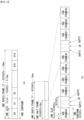
- FIG. 1 shows the structure of a radio frame in a wireless communication system to which an embodiment of the disclosure may be applied.
- 3GPP LTE/LTE-A support a radio frame structure type 1 which may be applicable to Frequency Division Duplex (FDD) and a radio frame structure which may be applicable to Time Division Duplex (TDD).
- FDD Frequency Division Duplex
- TDD Time Division Duplex
- FIG. 1(a) exemplifies a radio frame structure type 1.
- the type 1 radio frame may be applied to both of full duplex FDD and half duplex FDD.
- a radio frame includes 10 subframes.
- One subframe includes contiguous two slots in the time domain, and subframe i includes slot 2i and slot 2i+1.
- the time required for transmitting a subframe is referred to as a transmission time interval (TTI).
- TTI transmission time interval
- the length of the subframe i may be 1 ms and the length of a slot may be 0.5 ms.
- a UL transmission and a DL transmission I the FDD are distinguished in the frequency domain. Whereas there is no restriction in the full duplex FDD, a UE may not transmit and receive simultaneously in the half duplex FDD operation.
- One slot includes a plurality of Orthogonal Frequency Division Multiplexing (OFDM) symbols in the time domain and includes a plurality of Resource Blocks (RBs) in a frequency domain.
- OFDM symbols are used to represent one symbol period because OFDMA is used in downlink.
- An OFDM symbol may be called one SC-FDMA symbol or symbol period.
- An RB is a resource allocation unit and includes a plurality of contiguous subcarriers in one slot.
- FIG. 1(b) shows frame structure type 2.
- 'D' represents a subframe for a DL transmission
- 'U' represents a subframe for UL transmission
- 'S' represents a special subframe including three types of fields including a Downlink Pilot Time Slot (DwPTS), a Guard Period (GP), and an Uplink Pilot Time Slot (UpPTS).
- DwPTS Downlink Pilot Time Slot
- GP Guard Period
- UpPTS Uplink Pilot Time Slot
- 0 and 5 subframes and a DwPTS are used for only downlink transmission.
- An UpPTS and a subframe subsequent to a subframe are always used for uplink transmission.
- Such uplink-downlink configurations may be known to both an eNB and UE as system information.
- An eNB may notify UE of a change of the uplink-downlink allocation state of a radio frame by transmitting only the index of uplink-downlink configuration information to the UE whenever the uplink-downlink configuration information is changed.
- configuration information is kind of downlink control information and may be transmitted through a Physical Downlink Control Channel (PDCCH) like other scheduling information.
- Configuration information may be transmitted to all UEs within a cell through a broadcast channel as broadcasting information.
- PDCCH Physical Downlink Control Channel
- Table 2 represents configuration (length of DwPTS/GP/UpPTS) of a special subframe.
- Special subframe configuration Normal cyclic prefix in downlink Extended cyclic prefix in downlink DwPTS UpPTS DwPTS UpPTS Normal cyclic prefix in uplink Extended cyclic prefix in uplink Normal cyclic prefix in uplink Extended cyclic prefix in uplink 0 6592 ⁇ T s 2192 ⁇ T s 2560 ⁇ T s 7680 ⁇ T s 2192 ⁇ T s 2560 ⁇ T s 1 19760 ⁇ T s 20480 ⁇ T s 2 21952 ⁇ T s 23040 ⁇ T s 3 24144 ⁇ T s 25600 ⁇ T s 4 26336 ⁇ T s 7680 ⁇ T s 4384 ⁇ T s 5120 ⁇ T s 5 6592 ⁇ T s 4384 ⁇ T s 5120 ⁇ T s 20480 ⁇ T s 6 19760 ⁇ T s 23040 ⁇ T s 7 21952 ⁇ T s
- the structure of a radio subframe according to the example of FIG. 1 is just an example, and the number of subcarriers included in a radio frame, the number of slots included in a subframe and the number of OFDM symbols included in a slot may be changed in various manners.
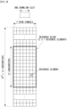
- FIG. 2 is a diagram illustrating a resource grid for one downlink slot in a wireless communication system to which an embodiment of the disclosure may be applied.
- one downlink slot includes a plurality of OFDM symbols in a time domain. It is described herein that one downlink slot includes 7 OFDMA symbols and one resource block includes 12 subcarriers for exemplary purposes only, and the disclosure is not limited thereto.
- Each element on the resource grid is referred to as a resource element, and one resource block (RB) includes 12 ⁇ 7 resource elements.
- the number of RBs N ⁇ DL included in a downlink slot depends on a downlink transmission bandwidth.
- the structure of an uplink slot may be the same as that of a downlink slot.
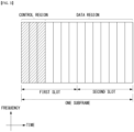
- FIG. 3 shows the structure of a downlink subframe in a wireless communication system to which an embodiment of the disclosure may be applied.
- a maximum of three OFDM symbols located in a front portion of a first slot of a subframe correspond to a control region in which control channels are allocated, and the remaining OFDM symbols correspond to a data region in which a physical downlink shared channel (PDSCH) is allocated.
- Downlink control channels used in 3GPP LTE include, for example, a physical control format indicator channel (PCFICH), a physical downlink control channel (PDCCH), and a physical hybrid-ARQ indicator channel (PHICH).
- a PCFICH is transmitted in the first OFDM symbol of a subframe and carries information about the number of OFDM symbols (i.e., the size of a control region) which is used to transmit control channels within the subframe.
- a PHICH is a response channel for uplink and carries an acknowledgement (ACK)/not-acknowledgement (NACK) signal for a Hybrid Automatic Repeat Request (HARQ).
- Control information transmitted in a PDCCH is called Downlink Control Information (DCI).
- DCI includes uplink resource allocation information, downlink resource allocation information, or an uplink transmission (Tx) power control command for a specific UE group.
- a PDCCH may carry information about the resource v and transport format of a downlink shared channel (DL-SCH) (this is also called an "downlink grant"), resource allocation information about an uplink shared channel (UL-SCH) (this is also called a “uplink grant”), paging information on a PCH, system information on a DL-SCH, the resource allocation of a higher layer control message, such as a random access response transmitted on a PDSCH, a set of transmission power control commands for individual UE within specific UE group, and the activation of a Voice over Internet Protocol (VoIP), etc.
- a plurality of PDCCHs may be transmitted within the control region, and UE may monitor a plurality of PDCCHs.
- a PDCCH is transmitted on a single Control Channel Element (CCE) or an aggregation of some contiguous CCEs.
- CCE is a logical allocation unit that is used to provide a PDCCH with a coding rate according to the state of a radio channel.
- a CCE corresponds to a plurality of resource element groups.
- the format of a PDCCH and the number of available bits of a PDCCH are determined by an association relationship between the number of CCEs and a coding rate provided by CCEs.
- An eNB determines the format of a PDCCH based on DCI to be transmitted to UE and attaches a Cyclic Redundancy Check (CRC) to control information.
- CRC Cyclic Redundancy Check
- a unique identifier (a Radio Network Temporary Identifier (RNTI)) is masked to the CRC depending on the owner or use of a PDCCH. If the PDCCH is a PDCCH for specific UE, an identifier unique to the UE, for example, a Cell-RNTI (C-RNTI) may be masked to the CRC.
- RNTI Radio Network Temporary Identifier
- a paging indication identifier for example, a Paging-RNTI (P-RNTI) may be masked to the CRC.
- P-RNTI Paging-RNTI
- SIB System Information Block
- SI-RNTI System Information-RNTI
- RA-RNTI Random Access-RNTI
- the enhanced PDCCH (EPDCCH) carries UE-specific signaling.
- the EPDCCH is located in a UE-specifically configured physical resource block (PRB).
- PRB physical resource block
- the PDCCH may be transmitted in up to first three OFDM symbols in the first slot in the subframe as set forth above, the EPDCCH may be transmitted in a resource region other than the PDCCH.
- the point (i.e., symbol) where the EPDCCH starts in the subframe may be configured in the UE via higher layer signaling (e.g., RRC signaling).
- the EPDCCH may carry the transmission format related to DL-SCH, resource allocation and HARQ information, transmission format related to UL-SCH, resource allocation and HARQ information, and resource allocation information related to sidelink shared channel (SL-SCH) and physical sidelink control channel (PSCCH). Multiple EPDCCHs may be supported.
- the UE may monitor the EPCCH's set.
- the EPDCCH may be transmitted by way of one or more consecutive enhanced CCEs (ECCEs), and the number of ECCEs per EPDCCH may be determined depending on each EPDCCH format.
- ECCEs enhanced CCEs
- Each ECCE may consist of a plurality of enhanced resource element groups (EREGs).
- the EREG is used to define mapping of ECCE to RE.
- the UE may monitor the plurality of EPDCCHs.
- one or two EPDCCH sets may be configured in one PRB pair in which the UE monitors EPDCCH transmission.
- Different coding rates for EPCCH may be realized by merging different numbers of ECCEs.
- the EPCCH may use localized transmission or distributed transmission and, thus, mapping of ECCE to RE in PRB may be varied.
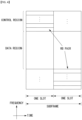
- FIG. 4 shows the structure of an uplink subframe in a wireless communication system to which an embodiment of the disclosure may be applied.
- the uplink subframe may be divided into a control region and a data region in a frequency domain.
- a physical uplink control channel (PUCCH) carrying uplink control information is allocated to the control region.
- a physical uplink shared channel (PUSCH) carrying user data is allocated to the data region.
- PUCCH physical uplink control channel
- PUSCH physical uplink shared channel
- a Resource Block (RB) pair is allocated to a PUCCH for one UE within a subframe. RBs belonging to an RB pair occupy different subcarriers in each of 2 slots. This is called that an RB pair allocated to a PUCCH is frequency-hopped in a slot boundary.
- NB-IoT Nearband-Internet of Things
- NB-IoT may mean a system for supporting low complexity and low power consumption with a system bandwidth (BW) corresponding to one physical resource block (1PRB) of a wireless communication system (e.g., an LTE system or NR system).
- BW system bandwidth
- 1PRB physical resource block
- NB-IoT may also be termed NB-LTE, NB-IOT enhancement, enhanced NB-IoT, further enhanced NB-IoT, or NB-NR. That is, NB-IoT may be replaced with other term defined, or to be defined, in the 3GPP standard. Hereinafter, for ease of description, such terms are collectively referred to as 'NB-IoT.'
- NB-IoT may be used primarily in communication schemes to implement IoT (i.e., things of internet) by allowing cellular systems to support such devices (or UEs) as machine-type communication (MTC) devices.
- MTC machine-type communication
- 1PRB of the existing system band is allocated for NB-IoT, thereby enabling efficient use of frequency.
- PRB and carrier as mentioned herein may be interpreted as meaning the same.
- NB-IoT frame structure, physical channel, multi-carrier operation, operation mode, or regular signal transmission/reception related to NB-IoT are described below considering those of the legacy LTE system, they may also be applicable to next-generation systems (e.g., NR systems). Further, the content related to NB-IoT in the disclosure may be expanded and applied to machine type communication (MTC) which is oriented to similar technical goals (e.g., low power, low cost, and enhanced coverage).
- MTC machine type communication
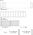
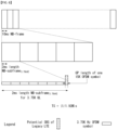
- the NB-IoT frame structure may be configured differently depending on subcarrier spacings. Specifically, FIG. 5 illustrates an example frame structure when the subcarrier spacing is 15kHz. FIG. 6 illustrates an example frame structure when the subcarrier spacing is 3.75kHz.
- the NB-IoT frame structure is not limited thereto, and the NB-IoT for other subcarrier spacing (e.g., 30kHz) may also be considered, with the time/frequency varied.
- LTE system frame structure-based NB-IoT frame structure is described herein as an example, this is merely an example, and schemes described herein may also be expanded and applied to NB-IoT based on next-generation system (e.g., NR) frame structure.
- next-generation system e.g., NR
- the NB-IoT frame structure for a subcarrier spacing of 15kHz may be configured to be the same as the frame structure of legacy systems (e.g., the LTE system). That is, a 10ms NB-IoT frame includes 10 1ms NB-IoT subframes, and a 1ms NB-IoT subframe may include two 0.5ms NB-IoT slots. Further, each 0.5ms NB-IoT may include seven OFDM symbols.
- a 10ms NB-IoT frame may include five 2ms NB-IoT subframes, and a 2ms NB-IoT subframe may include seven OFDM symbols and one guard period (GP). Further, the 2ms NB-IoT subframe may also be represented as an NB-IoT slot or NB-IoT resource unit (RU).
- NB-IoT downlink physical resources may be configured by referring to the physical resources of other wireless communication systems (e.g., the LTE system or NR system) except that the system bandwidth is a specific number of RBs (e.g., one RB, i.e., 180kHz).
- the physical resources of NB-IoT downlink may be configured with the resource region, with the resource grid of the LTE system shown above in FIG. C1 limited to one RB (i.e., 1 PRB) in the frequency domain.
- the physical resources of NB-IoT uplink may also be configured with the system bandwidth limited to one RB, as is the downlink.
- the resource grind for NB-IoT uplink may be represented as follows.
- the resource unit (RU) of NB-IoT uplink may be constituted with SC-FDMA symbols in the time domain and with N symb UL N slots UL consecutive subcarriers in the frequency domain.
- N sc RU and N symb UL may be given as in Table 4 below in the case of frame structure type 1 (i.e., FDD) and as in Table 5 in the case of frame structure type 2 (i.e., TDD).
- NPUSCH format ⁇ f N sc RU N slots UL N symb UL 1 3.75 kHz 1 16 7 15 kHz 1 16 3 8 6 4 12 2 2 3.75 kHz 1 4 15 kHz 1 4
- NPUSCH format ⁇ f Supported uplink-downlink configurations N sc RU N slots UL N symb UL 1 3.75 kHz 1, 4 1 16 7 15 kHz 1,2,3,4,5 1 16 3 8 6 4 12 2 2 3.75 kHz 1, 4 1 4 15 kHz 1,2,3,4,5 1 4
- the base station and/or UE supporting NB-IoT may be configured to transmit/receive physical channels and/or physical signals configured separately from legacy systems.
- physical channels and/or physical signals supported by NB-IoT are described below in detail.
- the OFDMA Orthogonal Frequency Division Multiple Access
- the OFDMA scheme may be applied to the NB-IoT disposed on based on the 15kHz subcarrier spacing.
- inter-subcarrier orthogonality may be provided so that co-existence with legacy systems (e.g., the LTE system or NR system) may be efficiently supported.
- the physical channel of the NB-IoT system may be represented in the form of adding 'N (Narrowband)' to be differentiated from legacy systems.
- downlink physical channels are defined as, e.g., NPBCH(Narrowband Physical Broadcast Channel), NPDCCH(Narrowband Physical Downlink Control Channel), and NPDSCH(Narrowband Physical Downlink Shared Channel)
- downlink physical signals may be defined as, e.g., NPSS(Narrowband Primary Synchronization Signal), NSSS(Narrowband Secondary Synchronization Signal), NRS(Narrowband Reference Signal), NPRS(Narrowband Positioning Reference Signal), and NWUS(Narrowband Wake Up Signal).
- the above-described NB-IoT disposed on physical channels and physical signals may be configured to be transmitted based on a time domain multiplexing scheme and/or frequency domain multiplexing scheme.
- repetition transmission may be performed for coverage enhancement.
- NB-IoT uses a newly defined DCI format.
- DCI formats defined for NB-IoT may be defined as, e.g., DCI format N0, DCI format N1, and DCI format N2.
- the SC-FDMA Single Carrier Frequency Division Multiple Access
- the SC-FDMA Single Carrier Frequency Division Multiple Access
- Multi-tone transmission and single-tone transmission may be supported for the NB-IoT uplink.
- multi-tone transmission is supported only in the 15kHz subcarrier spacing, and single-tone transmission may be supported for the 15kHz and 3.75kHz subcarrier spacings.
- the physical channel of the NB-IoT system may be represented in the form of adding 'N (Narrowband)' to be differentiated from legacy systems.
- uplink physical channels may be defined as NPRACH(Narrowband Physical Random Access Channel) and NPUSCH(Narrowband Physical Uplink Shared Channel), and uplink physical signals may be defined as, e.g., NDMRS(Narrowband Demodulation Reference Signal).
- NPUSCH may be configured as NPUSCH format 1 or NPUSCH format 2.
- NPUSCH format 1 may be used for UL-SCH transmission (or transport)
- NPUSCH format 2 may be used for uplink control information transmission, such as HARQ ACK signaling.
- repetition transmission may be performed for coverage enhancement.
- repetition transmission may be performed, with frequency hopping applied.
- Multi-carrier operation may mean that multiple carriers configured to have different uses (i.e., different types) when the base station and/or UE transmits/receives channels and/or signals in NB-IoT are used.
- NB-IoT may be operated in the above-described multi-carrier mode.
- NB-IoT carrier may be defined as anchor-type carrier (i.e., anchor carrier, anchor PRB) and non-anchor type carrier (i.e., non-anchor carrier, non-anchor PRB).
- Anchor carrier may mean a carrier to transmit NPSS, NSSS, NPBCH, and NPDSCH for system block information (N-SIB) for initial access purposes in view of the base station. That is, the NB-IoT carrier for initial access is denoted an anchor carrier, and the other(s) may be denoted non-anchor carrier. At this time, only one or multiple anchor carriers may be present on the system.
- N-SIB system block information
- NB-IoT operation mode Three operation modes may be supported in the NB-IoT system.
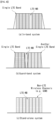
- FIG. 8 shows example of operation modes supported in the NB-IoT system.
- NB-IoT operation modes are described herein based on LTE bands, this is solely for ease of description, and the NB-IoT operation modes may also be expanded and applied to the bands of other systems (e.g., NR system bands).
- FIG. 8(a) illustrates an example in-band system
- FIG. 8(b) illustrates an example guard-band system
- FIG. 8(c) illustrates an example stand-alone system.
- in-band system, guard-band system, and stand-alone system respectively, may be represented as in-band mode, guard-band mode, and stand-alone mode.
- In-band system may mean a system or mode that uses specific 1RB (i.e., PRB) in the (legacy) LTE band for NB-IoT.
- the in-band system may be operated, with some resource blocks of the LTE system carrier allocated.
- Guard-band system may mean a system or mode that uses, for NB-IoT, a reserved space for the guard-band of the (legacy) LTE band.
- the guard-band system may be operated, with the guard-band of LTE carrier not used as a resource block in the LTE system allocated.
- the (legacy) LTE band may be configured to have a guard band of, at least, 100kHz at the end of each LTE band. To use 200kHz, two non-contiguous guard bands may be used.
- the in-band system and the guard-band system may be operated in the structure where NB-IoT coexists in the (legacy) LTE band.
- the standalone system may mean a system or mode configured independently from the (legacy) LTE band.
- the standalone system may be operated, with a frequency band (e.g., a GSM carrier reassigned in the future) used in the GERAN (GSM EDGE Radio Access Network) separately allocated.
- a frequency band e.g., a GSM carrier reassigned in the future
- GSM EDGE Radio Access Network GSM EDGE Radio Access Network
- the above-described three operation modes each may be operated independently or two or more operation modes may be operated in combination.
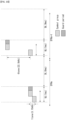
- FIG. 9 is a view illustrating physical channels and an example general signal transmission method available to NB-IoT.
- the NB-IoT UE may receive information via downlink (DL) from the base station, and the NB-IoT UE may transmit information to the base station via uplink (UL).
- DL downlink
- UL uplink
- the base station may transmit information to the NB-IoT UE via downlink
- the base station may receive information from the NB-IoT UE via uplink.
- the information communicated between the base station and the NB-IoT UE may include data and various pieces of control information, and there may be various physical channels depending on the kind/usage of information transmitted/received therebetween.
- the NB-IoT UE which powers back on or enters a new cell, may perform an initial cell search task, such as synchronization (S11). To that end, the NB-IoT UE may receive the NPSS and NSSS from the base station, perform synchronization with the base station, and obtain such information as, e.g., cell identity (ID). Further, the NB-IoT UE may receive the NPBCH from the base station and obtain in-cell broadcast information. Further, in the initial cell discovery step, the NB-IoT UE may receive a DL RS (Downlink Reference Signal) and identify the downlink channel state.
- a DL RS Downlink Reference Signal
- the base station may perform an initial cell discovery task, such as syncing with the UE.
- the base station may transmit the NPSS and NSSS to the NB-IoT UE, performing synchronization with the UE, and transfer such information as, e.g., cell identity (ID).
- the base station may transmit (or broadcast) the NPBCH to the NB-IoT UE, transferring in-cell broadcast information.
- the base station may transmit a DL RS to the NB-IoT UE in the initial cell discovery step, identifying the downlink channel state.
- the NB-IoT UE may obtain more specific system information by receiving the NPDCCH and its corresponding NPDSCH (S12).
- the base station may transfer more specific system information by transmitting the NPDCCH and its corresponding NPDSCH to the NB-IoT UE that has finished the initial cell discovery.
- the NB-IoT UE may perform a random access procedure for completing the attachment to the base station (S13 or S16).
- the NB-IoT UE may transmit a preamble to the base station via the NPRACH (S13).
- the NPRACH may be configured to be repeatedly transmitted based on, e.g., frequency hopping for, e.g., coverage enhancement.
- the base station may (repeatedly) receive the preamble via the NPRACH from the NB-IoT UE.
- the NB-IoT UE may receive an RAR (Random Access Response) for the preamble from the base station via the NPDCCH and its corresponding NPDSCH (S14).
- the base station may transmit the RAR (Random Access Response) for the preamble to the NB-IoT UE via the NPDCCH and its corresponding NPDSCH.
- the NB-IoT UE may transmit the NPUSCH to the base station using the scheduling information in the RAR (S15) and perform a contention resolution procedure, like the NPDCCH and its corresponding NPDSCH (S16).
- the base station may receive the NPUSCH from the UE using the scheduling information in the NB-IoT RAR and perform the contention resolution procedure.
- the NB-IoT UE having performed the above-described procedure may perform NPDCCH/NPDSCH reception (S17) and NPUSCH transmission (S18) as a regular uplink/downlink signal transmission procedure.
- the base station may perform NPDCCH/NPDSCH transmission and NPUSCH reception as a regular signal transmission/reception procedure for the NB-IoT UE.
- the NPBCH, NPDCCH, and NPDSCH may be repeatedly transmitted for, e.g., coverage enhancement.
- the UL-SCH (i.e., regular uplink data) and uplink control information may be transferred via the NPUSCH.
- the UL-SCH and uplink control information may be configured to be transmitted via different NPUSCH formats (e.g., NPUSCH format 1, NPPUSCH format 2).
- the control information transmitted by the UE to the base station may be denoted UCI (Uplink Control Information).
- the UCI may include, e.g., HARQ ACK/NACK(Hybrid Automatic Repeat and reQuest Acknowledgement/Negative-ACK), SR(Scheduling Request), and CSI(Channel State Information).
- the CSI includes, e.g., CQI(Channel Quality Indicator) and PMI(Precoding Matrix Indicator), RI(Rank Indication).
- the UCI may be transmitted typically via the NPUSCH. Further, at the request/indication from the network (e.g., the base station), the UE may transmit the UCI via the NPUSCH periodically, aperiodically, or semi-persistently.
- Narrowband (NB)-LTE is a system for supporting low complexity and low power consumption, with a system bandwidth (BW) corresponding to 1PRB (physical resource block) of the LTE system.
- BW system bandwidth
- the NB-LTE system may be used as a communication scheme to support devices, such as primarily machine-type communication (MTC), in the cellular system to thereby implement internet-of-things (IoT).
- MTC machine-type communication
- IoT internet-of-things
- OFDM parameters e.g., the subcarrier spacing of legacy LTE, identical to those of LTE may be used and 1PRB may be allocated for NB-LTE in the legacy LTE band to enable efficient use of frequency without additional band allocations.
- NB-LTE physical channels are defined as NPSS/NSSS, NPBCH, NPDCCH/NEPDCCH, and NPDSCH, and N is added to distinguish from LTE.
- each UE recognizes single PRB as each carrier, PRB as mentioned herein may mean the same thing as carrier.
- DCI format N0, N1, and N2 disclosed herein mean DCI format N0, N1, and N2 specified in the 3GPP TS 36.212[2] standard.
- uplink/downlink (UL/DL) in time division duplex via a single PRB.
- in-band mode and guard-band mode at least one or more configurations among several uplink downlink configurations of Table 1 are used.
- the DCI design in the legacy FDD system may be varied.
- MSG3 grant and DCI format NO are defined as in Tables 6 and 7 below.
- DCI format N0 Bits Flag for format N0/format N1 differentiation 1
- Subcarrier indication 6
- Resource assignment 3
- Scheduling delay 2
- Modulation and coding scheme 4
- Redundancy version 1
- Repetition nuber 3
- New data indicator 1
- DCI subframe repetition number 2
- HARQ process number 1
- SUM 24
- Subcarrier indication field ( I sc ) Set of Allocated subcarriers ( n sc ) 0 - 11 I sc 12-15 3( I sc - 12)+ ⁇ 0,1,2 ⁇ 16-17 6( I sc - 16)+ ⁇ 0,1,2,3,4,5 ⁇ 18 ⁇ 0,1,2,3,4,5,6,7,8,9,10,11 ⁇ 19-63 Reserved
- the subcarrier indication field of Tables 6 and 7 may be operated only with 6bits less one bit, i.e., 5bits.
- the uplink subcarrier spacing field of Table 7 may be operated even with 1bit less 1bit, i.e., no bit.
- 'unnecessary field' may be set as k bits.
- k may be subcarrier indication field 1 bit in DCI format NO and, in the narrowband MSG3 grant, k may be 2 bits, the sum of the subcarrier indication field 1 bit and uplink subcarrier spacing field 1 bit.
- Method 1 is a method of configuring the unnecessary field as a reserved field.
- This method has the advantage that it may be applied without a significant change in the specifications.
- Method 2 is a method of transmission, with the unnecessary field filled with 0s.
- Method 2 is similar to method 1 in that the unnecessary field is not deleted out but may be configured to play a role as a virtual CRC as transmission is performed, with the field filled always with Os.
- method 2 has the disadvantage that unless the base station changes to the U/D configuration supporting the 3.75kHz UL transmission, the field should be transmitted all the time.
- method 2 has some advantage because it is not the case that the field is never used.
- Method 3 is a method of creating additional states for subcarrier indication to use the unnecessary field.
- a new table may be created, applied, and used by adding T states to the 19 states of Table 8.
- Table 9 may be an example of the new table.
- Method 3 has the merit that fully dynamic resource allocation is possible for UL transmission using 15kHz subcarrier spacing, but the demerit that all of the states cannot be used upon multiplexing with the NPRACH supporting 3.75kHz subcarrier spacing.
- T is 14 or more for the total number of the states in the subcarrier indication field using 6 bits to be 33 or more.
- Subcarrier indication field ( I sc ) Set of Allocated subcarriers ( n sc ) 0-11 I sc 12-21 ( I sc -12 )+ ⁇ 0,1,2 ⁇ 22-30 ( I sc - 22 )+ ⁇ 0,1,2,3 ⁇ 31-37 ( I sc - 31 )+ ⁇ 0,1,2,3,4,5 ⁇ 38 ⁇ 0,1,2,3,4,5,6,7,8,9,10,11 ⁇ 39-63 Reserved
- Method 4 is a method of deleting out the unnecessary field.
- DCI format NO may be configured to reduce the subcarrier indication field from 6bits to 5bits.
- the subcarrier indication field may be reduced from 6bits to 5bits and it may be configured to delete out uplink subcarrier spacing field 1bit.
- Method 4 is most advantageous in that it has no unnecessary resource waste.
- the base station may previously determine the UL subcarrier spacing supported in a specific UL/DL configuration.
- the UE receives UL subcarrier spacing information supported in the current NB-IoT cell for the SIB (which may be SIB1-NB specifically) where the tdd-Config-NB parameter is to be transmitted using N bits.
- SIB which may be SIB1-NB specifically
- the reason why such selection is possible as to support only a specific UL subcarrier spacing (specifically 15kHz subcarrier spacing) depending on the UL/DL configuration used by a specific cell is that one slot duration of the 3.75kHz subcarrier spacing is 2ms.
- the base station selects a specific UL/DL configuration and it is not easy to secure two contiguous UL subframes considering various contexts (e.g., invalid UL subframe).
- the base station intends to support only 15kHz subcarrier spacing for ease of scheduling although both the 3.75kHz subcarrier spacing and 15kHz subcarrier spacing are supportable, it may be configured not to use the 3.75 kHz subcarrier spacing.
- the base station may configure to use only 15kHz UL subcarrier spacing for ease of resource allocation or scheduling delay.
- the base station determines to supports only the 3.75kHz subcarrier spacing although the 3.75 kHz subcarrier spacing and 15 kHz subcarrier spacing both are supportable, it may be configured not to use the 15 kHz subcarrier spacing.
- Such base station's determination (i.e., using a specific UL subcarrier spacing only) is transferred to the UE via the SIB.
- the UE performs decoding/monitoring with the belief that the MSG3 grant size and DCI format NO size are modified and transmitted from the base station according to such determination.
- the uplink subcarrier spacing field needs to be modified.
- the uplink subcarrier spacing field of Table 7 may be operated even with 1bit less 1bit, i.e., no bit.
- the 'unnecessary field' denoted in the above methods may be set to k bit(s).
- k may be Uplink subcarrier spacing field 1bit.
- the field of Tables 9 and 10 needs to be modified as mentioned in MSG3 Grant and DCI format NO design detail for different U/D configurations.
- the subcarrier indication field of Tables 9 and 10 may be operated only with 6bits less one bit, i.e., 5bits.
- the uplink subcarrier spacing field of Table 7 may be operated even with 1bit less 1bit, i.e., no bit.
- 'unnecessary field' may be set as k bits.
- k may be subcarrier indication field 1 bit in DCI format NO and, in the narrowband MSG3 grant, k may be 2 bits, the sum of the subcarrier indication field 1 bit and uplink subcarrier spacing field 1 bit.
- TDD NB-IoT system supports both 3.75 kHz subcarrier spacing and 15 kHz subcarrier spacing, it may be configured to use the same method applied to the FDD NB-IoT system.
- the UL subcarrier spacing of UL grant may be determined to use the same value as the subcarrier spacing received via the MSG3 grant.
- Rel. 15 TDD NB-IoT may try to fetch a different number of UL multi-tones, as operated in the 15 kHz subcarrier spacing (SCS) according to a specific U/D configuration number, from that used in FDD
- SCS subcarrier spacing
- legacy FDD supports multi-tone transmission configured of 3 tones, 6 tones, and 12 tones, as well as single tone transmission.
- Rel. 15 TDD NB-IoT intends to support multi-tone transmission configured of 4 tones and 12 tones and single tone transmission in a specific U/D configuration (specifically, U/D configuration 3 or 6, i.e., the cases where three or more consecutive UL SFs are secured).
- methods of configuring how many tones a multi-tone is configured with according to a specific U/D configuration may be summed up as follows.
- Method 1 refers to a method that defines all transmissions (i.e., single tone and/or multi-tone) supportable in TDD in the specifications and configures them to be explicitly configurable via SIB.
- UL subcarrier spacing information supported in the current NB-IoT cell may be transferred via N bits in the SIB (specifically SIB 1-NB) where tdd-Config-NB parameter is to be transmitted in the above-described UL subcarrier spacing indication in SIB by N bits (N is a positive integer), it may be configured that the transfer is possible, tied up with the information.
- this may be represented as in the following five scenario cases.
- 3.75 kHz SCS only is supported, (2) where 15 kHz SCS alone is supported, and UL transmission configured of ⁇ single tone, 3-tones, 6-tones, 12-tones ⁇ is supported, (3) where only 15 kHz SCS is supported, and UL transmission configured of ⁇ single tone, 4-tones, 12-tones ⁇ is supported, (4) where both 3.75 kHz and 15 kHz SCS are supported, and UL transmission configured of ⁇ single tone, 3-tones, 6-tones, 12-tones ⁇ for15 kHz SCS is supported, (5) where 3.75 kHz and 15 kHz SCS both are supported, and UL transmission configured of ⁇ single tone, 4-tones, 12-tones ⁇ for 15 kHz SCS is supported.
- N may be 3bits.
- this method features transferring information independently form UL/DL configuration.
- Method 2 refers to a method that defines all transmissions (i.e., single tone and/or multi-tone) supportable in TDD and configures them to be implicitly configurable via SIB.
- this method is a method of pre-agreeing on what UL transmissions are to be used depending on configured UL/DL configuration values or configured SCS values.
- Table 10 shows a UL transmission set for UL/DL configurations when 15 kHz
- the UE may be configured that the UE is aware of the UL transmission set currently available in the cell based on the UL/DL configuration information transmitted via SIB and information for supported subcarrier spacing (SCS).
- SIB UL/DL configuration information transmitted via SIB
- SIB information for supported subcarrier spacing
- DCI format NO may be modified when the NB-IoT system only supports 15kHz SCS, but not 3.75kHz SCS, so the subcarrier indication field of DCI format NO may be modified and applied as shown in Table 11 even when 15 kHz SCS with single tone, 4-tones, 12-tones is supported.
- Subcarrier indication field ( I sc ) Set of Allocated subcarrier ( n sc ) 0 - 11 I sc 12-14 4( I sc -12)+ ⁇ 0,1,2,3 ⁇ 15 ⁇ 0,1,2,3,4,5,6,7,8,9,10,11 ⁇
- Table 11 represents that single tone, 4-tones, and 12-tones may be expressed with only 4bits.
- 'unnecessary field' k is 2bits.
- the size of DCI format is variable depending on UL/DL configurations and, in each case, the size of the field may be determined depending on the number of states in the relevant table.
- the above-described method deals with the variability of the DCI format size depending on UL/DL configurations, and this may be further generalized so that the UL/DL configuration is repeated per specific period (e.g., Xms), and the DCI format size is variable depending on the minimum or maximum value (e.g., L ms) of the number of consecutive UL subframes in X ms.
- the minimum or maximum value e.g., L ms
- the relevant field may be represented with 5bits as in Table 12 (which results from reducing only reserved states in Table 8) and, where L is 3ms, the relevant field may be represented using 4bits as in Table 8.
- Subcarrier indication field ( I sc ) Set of Allocated subcarriers ( n sc ) 0-11 I sc 12-15 3( I sc - 12)+ ⁇ 0,1,2 ⁇ 16-17 6( I sc -16)+ ⁇ 0,1,2,3,4,5 ⁇ 18 ⁇ 0,1,2,3,4,5,6,7,8,9,10,11 ⁇ 19-31 Reserved
- the DCI format size is variable.
- the relevant field may be represented with 4 bits as in Table 11.
- L' is 1, the UL transmission configured of ⁇ single tone, 3-tones, 6-tones, 12-tones ⁇ is supported and, where L' is 2, the UL transmission configured of ⁇ single tone, 4-tones, 12-tones ⁇ is supported.
- the NPUSCH may be transmitted for a specific UpPTS symbol number (e.g., 7 symbols) or more, a specific part of the default RU may be punctured (or rate-matched).
- a specific UpPTS symbol number e.g., 7 symbols
- a specific part of the default RU may be punctured (or rate-matched).
- transmission may commence at the start point of a special subframe, and a specific number of first UL symbols (e.g., 14-U symbols) may be subject to puncturing (or rate matching).
- the start point of the default RU is transmitted at the UpPTS starting symbol configured from the higher layer, and the other non-transmitted back portion may be punctured (or rate-matched).
- TDD is configured to transmit, back-to-back, G symbol groups in consecutive UL SFs.
- a single preamble is constituted of P symbol groups.
- the NPRACH preamble format design is defined to be different from that in FDD NB-IoT, use of the NPRACH resource configurations used in legacy FDD may cause the following issues.
- the base station needs to set the period of the NPRACH resource to be, at least, 1280ms or more.
- the resource for NPRACH preamble transmission is always present at one side (one of 12, 24, 36, and 48 subcarriers) of 1RB in the relevant carrier.
- FIG. 11 illustrates an example in which when the period is configured as 1280ms, as much NPACH resource as 12 subcarriers is allocated.
- the UE selects and transmits a subcarrier (i.e., NPRACH preamble) configured to be able to transmit the MSG3 multi-tones of the NPRACH resource.
- a subcarrier i.e., NPRACH preamble
- the base station configures the UE to be able to transmit 15kHz 12-tones MSG3, the UE introduces the NPRACH resource upon transmitting MGG3.
- the base station may configure the period of NPRACH resource.
- the UE picks an NPRACH resource from among the carriers bundled up at the same CE level based on its probability already known, it may not previously be aware of the period per resource or the number of subcarriers allocated to the resource.
- Method 1 is to configure different carriers for transmission of MSG1 and MSG3.
- Method 1 It may be configured to dynamically pick the carrier for transmission of MSG3 using, e.g., the reserved field or reserved state of RAR (grant) or DCI scheduling RAR.
- This method has advantages in light of resource utilization since the base station may determine to dynamically configure different carriers.
- this method is advantageous from a carrier load balancing standpoint because it may configure the UEs, which have transmitted MSG1 using the same NPRACH resource, to MSG3 on different carriers.
- (1-2) It may be configured that carriers to transmit MSG3 are previously transferred independently per NPRACH resource via SIB2 or SIB22.
- This method has advantages in that it may choose one from among more MSG3 carriers and transmit because it does not use RAR (grant) or DCI scheduling RAR (i.e., because the field is broader).
- MSG3 is transferred using 1bit indicator to use a different UL carrier from MSG1 via RAR (grant) or DCI scheduling RAR.
- this method may actively configure MSG3 to be transmitted on a different UL carrier from MSG1 under the determination of the base station and use only one bit field of RAR (grant) or DCI scheduling RAR.
- DCI format N1 DCI format N1
- the indicator is set to be activated, the UL carrier for legacy UL unicast is used as the carrier for transmission of MSG3, otherwise MSG3 is transmitted on the same carrier as the carrier for MSG1 transmission.
- Such an occasion may exist where a method for configuring the UL carrier for MSG1 transmission and the UL carrier for MSG3 transmission to differ from each other, such as 1-1, 1-2, or 1-3, has already been applied, and method 1-4 is added.
- the indicator may mean that an MSG3 transmission UL carrier is determined according to a preset method (e.g., 1-1, 1-2, or 1-3).
- this method is advantageous from a carrier load balancing standpoint because it may configure the UEs, which have transmitted MSG1 using the same NPRACH resource, to MSG3 on different UL carriers.
- the UL carrier set for transmitting MSG3 may be configured to be the same as the UL carrier set for transmitting MSG1, this may be configured independently by the base station.
- the UE already aware of the carriers capable of transmitting MSG1 need not further know the UL carrier set information for MSG3.
- the base station configures the same independently, it is advantageous in light of carrier load balancing.
- the UL carrier set is transmitted via an SIB (e.g., SIB2 or SIB22).
- SIB e.g., SIB2 or SIB22.
- Method 2 is a method of configuring different UL grant interpretation methods included and transmitted in RAR for MSG3 transmission although the same carrier is used for transmission of MSG1 and MSG3.
- the UE may be configured to determine that the UL grant is invalid and MSG1 retransmission or MSG3 retransmission is started.
- NPRACH resource For example, if the number of subcarriers used in the NPRACH resource is 12, and the NPRACH offset is 0 or 36, number state number 18 (15kHz 12 tone) and state number 16 or 17 (6 tone) cannot be used.
- the NPRACH offset may be configured to transmit number 18 state using 9 tone of ⁇ 3, 4, 5, 6, 7, 8, 9, 10, 11 ⁇ and, if the NPRACH offset is 36, to transmit number 18 state using 9 tone of ⁇ 0, 1, 2, 3, 4, 5, 6, 7, 8 ⁇ .
- NPRACH offset is 0, it may be configured that number 16 state is interpreted as 6(I SC -16)+ ⁇ 3, 4, 5, 6, 7, 8 ⁇ and number 17 state is interpreted as it is, (i.e., 6(I SC -16)+ ⁇ 0, 1, 2, 3, 4, 5 ⁇ ).
- NPRACH offset is 36, it may be configured that number 17 state is interpreted as 6(I SC -17)+ ⁇ 3, 4, 5, 6, 7, 8 ⁇ and number 16 state is interpreted as it is, (i.e., 6(I SC -16)+ ⁇ 0, 1, 2, 3, 4, 5 ⁇ ).
- MSG2, MSG3, and MSG4 carriers may be independently configured which need to be used until the procedure is done.
- MSG2 reception carriers, and/or MSG3 transmission carriers, and/or MSG4 reception carriers per NPRACH resource or per MSG1 transmission carrier.
- This method also provides the advantage that the base station may perform carrier load balancing at its own discretion.
- FIG. 12 is a flowchart illustrating an example operation method of a UE performing a method of transmitting a message for performing a random access procedure proposed in the disclosure.
- the UE transmits a first message to the base station based on the system information (S1220).
- the UE receives a second message, which is a response to the first message, from the base station (S1230).
- the third message is transmitted using a carrier different from the carrier used to transmit the first message.
- the UE may receive downlink control information (DCI) from the base station through a physical downlink control channel (NPDCCH)
- DCI downlink control information
- NPDCCH physical downlink control channel
- the carrier for transmission of the third message may be configured via the system information.
- the carrier for transmission of the third message may be configured via the DCI or second message.
- system information may include information for resources where the third message is transmittable and, based on the information, the carrier where the third message is transmitted may be configured via the DCI or the second message.
- the NPDCCH may be one for unicast transmission.
- the third message may be transmitted using the carrier used for uplink unicast.
- FIG. 13 is a flowchart illustrating an example operation method of a base station performing a method of transmitting a message for performing a random access procedure proposed in the disclosure.
- system information is transmitted to the UE (S1310).
- the base station receives a third message from the UE (S1340).
- FIG. 14 is a block diagram illustrating a configuration of a wireless communication device according to an embodiment of the disclosure.
- a wireless communication system includes a base station 1410 and a plurality of UEs 1420 positioned in the coverage of the base station 1410.
- the base station 1410 includes a processor 1411, a memory 1412, and a radio frequency (RF) unit 1413.
- the processor 1411 implements the functions, processes or steps, and/or methods proposed above in connection with FIGS. 1 to 13 .
- Wireless interface protocol layers may be implemented by the processor 1411.
- the memory 1412 is connected with the processor 1411 to store various pieces of information for driving the processor 1411.
- the RF unit 1413 is connected with the processor 1411 to transmit and/or receive wireless signals.
- the UE 1420 includes a processor 1421, a memory 1422, and an RF unit 1423.
- the processor 1421 implements the functions, processes or steps, and/or methods proposed above in connection with FIGS. 1 to 13 .
- the memory 1422 is connected with the processor 1421 to store various pieces of information for driving the processor 1421.
- the RF unit 1423 is connected with the processor 1421 to transmit and/or receive wireless signals.
- the memory 1412 and 1422 may be positioned inside or outside the processor 1411 and 1421 and be connected with the processor 1411 and 1421 via various known means.
- the base station 1410 and/or the UE 1420 may include a single or multiple antennas.
- the embodiments of the disclosure may be implemented by various means, e.g., hardware, firmware, software, or a combination thereof.
- an embodiment of the disclosure may be implemented with, e.g., one or more application specific integrated circuits (ASICs), digital signal processors (DSPs), digital signal processing devices (DSPDs), programmable logic devices (PLDs), field programmable gate arrays (FPGAs), processors, controllers, micro-controllers, or microprocessors.
- ASICs application specific integrated circuits
- DSPs digital signal processors
- DSPDs digital signal processing devices
- PLDs programmable logic devices
- FPGAs field programmable gate arrays
- processors controllers, micro-controllers, or microprocessors.
- an embodiment of the disclosure may be implemented as a module, procedure, or function performing the above-described functions or operations.
- the software code may be stored in a memory and driven by a processor.
- the memory may be positioned inside or outside the processor to exchange data with the processor by various known means.
Landscapes
- Engineering & Computer Science (AREA)
- Signal Processing (AREA)
- Computer Networks & Wireless Communication (AREA)
- Physics & Mathematics (AREA)
- Mathematical Physics (AREA)
- Computer Security & Cryptography (AREA)
- Mobile Radio Communication Systems (AREA)
Claims (11)
- Verfahren zum Übertragen, durch ein Benutzergerät, UE (1420), einer Nachricht zum Durchführen einer Direktzugriffsprozedur in einem drahtlosen Kommunikationssystem, wobei das Verfahren umfasst:Empfangen (S1210) eines Systeminformationsblocks, SIB, von einer Basisstation (1410), wobei der SIB Zeitduplex-, TDD-, Uplink-Downlink-Konfigurationsinformationen für eine bedienende Zelle des UE enthält und Informationen über den Uplink-Subträgerabstand, SCS, die in der bedienenden Zelle unterstützt werden;Übertragen (S1220) einer ersten Nachricht an die Basisstation (1410) basierend auf den TDD-Uplink-Downlink-Konfigurationsinformationen und dem Uplink-SCS des SIB, wobei die erste Nachricht eine Direktzugriffspräambel ist;Empfangen (S1230) einer zweiten Nachricht von der Basisstation (1410), wobei die zweite Nachricht eine Antwort auf die erste Nachricht ist; undÜbertragen (S1240) einer dritten Nachricht an die Basisstation (1410) unter Verwendung eines Trägers, der sich von einem Träger unterscheidet, der zum Übertragen der ersten Nachricht verwendet wird,wobei der Uplink-SCS der bedienenden Zelle in Abhängigkeit von den TDD-Uplink-Downlink-Konfigurationsinformationen der bedienenden Zelle bestimmt wird, undwobei i) eine Nutzdatengröße von Planungsinformationen für die Ressourcenzuweisung der dritten Nachricht in der zweiten Nachricht, und ii) die Anzahl von Subträgern, die zum Übertragen der dritten Nachricht verwendet werden, basierend auf dem Uplink-SCS bestimmt werden.
- Verfahren nach Anspruch 1, ferner umfassend:
vor dem Übertragen der ersten Nachricht, Empfangen von Downlink-Steuerinformationen, DCI, von der Basisstation (1410). - Verfahren nach Anspruch 2, wobei
der Träger, der zum Übertragen der dritten Nachricht verwendet wird, basierend auf den DCI oder der zweiten Nachricht bestimmt wird. - Verfahren nach Anspruch 2,
wobei der Träger, der zum Übertragen der dritten Nachricht verwendet wird, basierend auf dem SIB bestimmt wird. - Verfahren nach Anspruch 2, wobeiein physischer Downlink-Steuerkanal, PDCCH, der die DCI enthält, zur Unicast-Übertragung dient, und wobeidie dritte Nachricht unter Verwendung eines Trägers übertragen wird, der für Uplink-Unicast verwendet wird.
- Benutzergerät, UE (1420), das konfiguriert ist, um ein Verfahren zum Übertragen einer Nachricht zum Durchführen einer Direktzugriffsprozedur in einem drahtlosen Kommunikationssystem durchzuführen, wobei das UE (1420) umfasst:ein Hochfrequenz-, HF-, Modul (1423), zum Übertragen/Empfangen eines Funksignals; undeinen Prozessor (1421), der funktionsfähig mit dem HF-Modul verbunden ist, wobei der Prozessor (1421) konfiguriert ist zum:Empfangen (S1210) eines Systeminformationsblocks, SIB, von einer Basisstation (1410), wobei der SIB Zeitduplex-, TDD-, Uplink-Downlink-Konfigurationsinformationen für eine bedienende Zelle des UE enthält und Informationen über den Uplink-Subträgerabstand, SCS, die in der bedienenden Zelle unterstützt werden;Übertragen (S1220) einer ersten Nachricht an die Basisstation (1410) basierend auf den TDD-Uplink-Downlink-Konfigurationsinformationen und dem Uplink-SCS des SIB, wobei die erste Nachricht eine Direktzugriffspräambel ist;Empfangen (S1230) einer zweiten Nachricht von der Basisstation (1410), wobei die zweite Nachricht eine Antwort auf die erste Nachricht ist; undÜbertragen (S1240) einer dritten Nachricht an die Basisstation (1410) unter Verwendung eines Trägers, der sich von einem Träger unterscheidet, der zum Übertragen der ersten Nachricht verwendet wird,wobei der Uplink-SCS der bedienenden Zelle in Abhängigkeit von den TDD-Uplink-Downlink-Konfigurationsinformationen der bedienenden Zelle bestimmt wird, undwobei i) eine Nutzdatengröße von Planungsinformationen für die Ressourcenzuweisung der dritten Nachricht in der zweiten Nachricht, und ii) die Anzahl von Subträgern, die zum Übertragen der dritten Nachricht verwendet werden, basierend auf dem Uplink-SCS bestimmt werden.
- UE (1420) nach Anspruch 6, wobei der Prozessor (1421) konfiguriert ist zum:
Empfangen von Downlink-Steuerinformationen, DCI, von der Basisstation (1410). - UE (1420) nach Anspruch 7, wobei
der Träger, der zum Übertragen der dritten Nachricht verwendet wird, basierend auf den DCI oder der zweiten Nachricht bestimmt wird. - UE (1420) nach Anspruch 6, wobei:
der Träger, der zum Übertragen der dritten Nachricht verwendet wird, basierend auf dem SIB bestimmt wird. - Verfahren zum Übertragen, durch eine Basisstation (1410), einer Nachricht, zum Durchführen einer Direktzugriffsprozedur in einem drahtlosen Kommunikationssystem, wobei das Verfahren umfasst:Übertragen (S1310) eines Systeminformationsblocks, SIB, an ein Benutzergerät, UE (1420), wobei der SIB Zeitduplex-, TDD-, Uplink-Downlink-Konfigurationsinformationen für eine bedienende Zelle des UE enthält und Informationen über den Uplink-Subträgerabstand, SCS, die in der bedienenden Zelle unterstützt werden;Empfangen (S1320) einer ersten Nachricht vom UE (1420) basierend auf den TDD-Uplink-Downlink-Konfigurationsinformationen und dem Uplink-SCS des SIB, wobei die erste Nachricht eine Direktzugriffspräambel ist;Übertragen (S1330) einer zweiten Nachricht an das UE (1420), wobei die zweite Nachricht eine Antwort auf die erste Nachricht ist; undEmpfangen (S1340) einer dritten Nachricht vom UE (1420) unter Verwendung eines Trägers, der sich von einem Träger unterscheidet, der zum Übertragen der ersten Nachricht verwendet wird,wobei der Uplink-SCS der bedienenden Zelle in Abhängigkeit von den TDD-Uplink-Downlink-Konfigurationsinformationen der bedienenden Zelle bestimmt wird, undwobei i) eine Nutzdatengröße von Planungsinformationen für die Ressourcenzuweisung der dritten Nachricht in der zweiten Nachricht, und ii) die Anzahl von Subträgern, die zum Übertragen der dritten Nachricht verwendet werden, basierend auf dem Uplink-SCS bestimmt werden.
- Basisstation (1410), die konfiguriert ist, um ein Verfahren zum Übertragen einer Nachricht zum Durchführen einer Direktzugriffsprozedur in einem drahtlosen Kommunikationssystem durchzuführen, wobei die Basisstation (1410) umfasst:ein Hochfrequenz-, HF-, Modul (1413), zum Übertragen/Empfangen eines Funksignals; undeinen Prozessor (1411), der funktionsfähig mit dem HF-Modul verbunden ist, wobei der Prozessor konfiguriert ist zum:Übertragen (S1310) eines Systeminformationsblocks, SIB, an ein Benutzergerät, UE (1420), wobei der SIB Zeitduplex-, TDD-, Uplink-Downlink-Konfigurationsinformationen für eine bedienende Zelle des UE enthält und Informationen über den Uplink-Subträgerabstand, SCS, die in der bedienenden Zelle unterstützt werden;Empfangen (S1320) einer ersten Nachricht vom UE (1420) basierend auf den TDD-Uplink-Downlink-Konfigurationsinformationen und dem Uplink-SCS des SIB, wobei die erste Nachricht eine Direktzugriffspräambel ist;Übertragen (S1330) einer zweiten Nachricht an das UE (1420), wobei die zweite Nachricht eine Antwort auf die erste Nachricht ist; undEmpfangen (S1340) einer dritten Nachricht vom UE (1420) unter Verwendung eines Trägers, der sich von einem Träger unterscheidet, der zum Übertragen der ersten Nachricht verwendet wird,wobei der Uplink-SCS der bedienenden Zelle in Abhängigkeit von den TDD-Uplink-Downlink-Konfigurationsinformationen der bedienenden Zelle bestimmt wird, undwobei i) eine Nutzdatengröße von Planungsinformationen für die Ressourcenzuweisung der dritten Nachricht in der zweiten Nachricht, und ii) die Anzahl von Subträgern, die zum Übertragen der dritten Nachricht verwendet werden, basierend auf dem Uplink-SCS bestimmt werden.
Applications Claiming Priority (4)
| Application Number | Priority Date | Filing Date | Title |
|---|---|---|---|
| US201762582954P | 2017-11-08 | 2017-11-08 | |
| US201762608537P | 2017-12-20 | 2017-12-20 | |
| US201862634208P | 2018-02-23 | 2018-02-23 | |
| PCT/KR2018/013559 WO2019093793A1 (ko) | 2017-11-08 | 2018-11-08 | 무선 통신 시스템에서 랜덤 엑세스 절차를 수행하기 위한 메시지를 전송하는 방법 및 이를 위한 장치 |
Publications (3)
| Publication Number | Publication Date |
|---|---|
| EP3703458A1 EP3703458A1 (de) | 2020-09-02 |
| EP3703458A4 EP3703458A4 (de) | 2021-08-18 |
| EP3703458B1 true EP3703458B1 (de) | 2025-01-01 |
Family
ID=66438581
Family Applications (1)
| Application Number | Title | Priority Date | Filing Date |
|---|---|---|---|
| EP18876481.5A Active EP3703458B1 (de) | 2017-11-08 | 2018-11-08 | Verfahren zur übertragung von nachrichten zur durchführung von direktzugriffsverfahren in einem drahtlosen kommunikationssystem und vorrichtung dafür |
Country Status (5)
| Country | Link |
|---|---|
| US (1) | US11844111B2 (de) |
| EP (1) | EP3703458B1 (de) |
| KR (1) | KR102402352B1 (de) |
| CN (1) | CN111527787B (de) |
| WO (1) | WO2019093793A1 (de) |
Families Citing this family (5)
| Publication number | Priority date | Publication date | Assignee | Title |
|---|---|---|---|---|
| EP4333542A3 (de) * | 2018-01-24 | 2024-05-29 | Telefonaktiebolaget LM Ericsson (publ) | Mehrfach-tbs für msg3 in der datenübertragung während eines zufallszugriffs |
| EP3782424B1 (de) | 2018-04-17 | 2022-06-15 | Telefonaktiebolaget LM Ericsson (publ) | Berücksichtigung von folgedaten für frühe datenübertragung |
| CN116318563B (zh) * | 2021-12-17 | 2025-07-29 | 大唐移动通信设备有限公司 | Msg3发送方法、接收方法、装置及存储介质 |
| US12538275B2 (en) * | 2021-12-21 | 2026-01-27 | Electronics And Telecommunications Research Institute | Method and apparatus for radio communication of time sensitive network |
| US12426087B2 (en) | 2022-04-15 | 2025-09-23 | Electronics And Telecommunications Research Institute | Method and apparatus for resource allocation contention in distributed communication system |
Family Cites Families (14)
| Publication number | Priority date | Publication date | Assignee | Title |
|---|---|---|---|---|
| KR100903870B1 (ko) | 2006-11-03 | 2009-06-24 | 한국전자통신연구원 | 자원 할당 요청 방법 및 자원 할당 방법 |
| US20100322096A1 (en) * | 2009-06-23 | 2010-12-23 | Chia-Chun Hsu | Method of improving component carrier identification in a random access procedure in a wireless communication system and related communication device |
| US8917593B2 (en) * | 2010-03-18 | 2014-12-23 | Qualcomm Incorporated | Random access design in a multiple component carrier communication network |
| KR20110113484A (ko) * | 2010-04-09 | 2011-10-17 | 주식회사 팬택 | 다중 반송파 시스템에서 랜덤 액세스의 수행장치 및 방법 |
| WO2012071681A1 (zh) * | 2010-11-30 | 2012-06-07 | 富士通株式会社 | 无线通信终端、无线通信基站和它们的通信方法,以及实现该通信方法的程序和存储该程序的介质 |
| KR20130061628A (ko) | 2011-12-01 | 2013-06-11 | 에이서 인코포레이티드 | 이동 통신 디바이스, 셀룰러 스테이션, 다중 반송파 시스템, 및 랜덤 액세스 실패를 처리하기 위한 방법 |
| WO2017131459A1 (ko) * | 2016-01-29 | 2017-08-03 | 성균관대학교 산학협력단 | 사물인터넷 환경에서 커버리지 레벨과 서브캐리어 스페이싱 설정 및/또는 멀티-톤 설정을 고려한 랜덤 액세스 방법 |
| JP2017139673A (ja) | 2016-02-04 | 2017-08-10 | 株式会社Nttドコモ | ユーザ端末、無線基地局及び無線通信方法 |
| US20190037608A1 (en) | 2016-02-04 | 2019-01-31 | Ntt Docomo, Inc. | User terminal, radio base station, and radio communication method |
| CN107734667A (zh) * | 2016-08-12 | 2018-02-23 | 夏普株式会社 | 执行随机接入的方法、用户设备和基站 |
| EP3498032B1 (de) * | 2016-08-12 | 2020-04-29 | Telefonaktiebolaget LM Ericsson (PUBL) | Trägerkonfiguration für zufälligen zugriff |
| US10856317B2 (en) * | 2016-11-17 | 2020-12-01 | Huawei Technologies Co., Ltd. | System and method for uplink communications |
| CN110178333A (zh) * | 2017-01-06 | 2019-08-27 | Idac控股公司 | 与新无线电相关联的物理广播信道、初始上行链路传输和系统获取 |
| US10764888B2 (en) * | 2017-07-27 | 2020-09-01 | Yeongmoon SON | Method and apparatus to receive and transmit data in a mobile communication system with multiple SCS |
-
2018
- 2018-11-08 WO PCT/KR2018/013559 patent/WO2019093793A1/ko not_active Ceased
- 2018-11-08 CN CN201880084847.9A patent/CN111527787B/zh active Active
- 2018-11-08 EP EP18876481.5A patent/EP3703458B1/de active Active
- 2018-11-08 US US16/762,748 patent/US11844111B2/en active Active
- 2018-11-08 KR KR1020207013896A patent/KR102402352B1/ko active Active
Also Published As
| Publication number | Publication date |
|---|---|
| WO2019093793A1 (ko) | 2019-05-16 |
| KR102402352B1 (ko) | 2022-05-25 |
| EP3703458A1 (de) | 2020-09-02 |
| EP3703458A4 (de) | 2021-08-18 |
| KR20200062332A (ko) | 2020-06-03 |
| CN111527787A (zh) | 2020-08-11 |
| CN111527787B (zh) | 2023-08-04 |
| US20210176788A1 (en) | 2021-06-10 |
| US11844111B2 (en) | 2023-12-12 |
Similar Documents
| Publication | Publication Date | Title |
|---|---|---|
| US11716188B2 (en) | Method for transmitting and receiving data in wireless communication system and apparatus for the same | |
| US11271708B2 (en) | Method for transmitting or receiving signal in wireless communication system, and device therefor | |
| JP6786665B2 (ja) | アンライセンスバンドをサポートする無線アクセスシステムにおいて部分サブフレームを構成してスケジューリングする方法及びこれをサポートする装置 | |
| US10721775B2 (en) | Method for performing early data transmission in random access procedure in wireless communication system and apparatus therefor | |
| US11096222B2 (en) | Method for transmitting and receiving random access preamble in wireless communication system and apparatus therefor | |
| CN114696964B (zh) | 在无线通信系统中发送/接收数据的方法及其设备 | |
| EP3172856B1 (de) | Verfahren und benutzervorrichtung zum empfang von downlink-steuerinformationen sowie verfahren und basisstation zum senden von downlink-steuerinformationen | |
| EP3550922B1 (de) | Verfahren und vorrichtung zum übertragen und empfangen von zufälligen zugriffsvorgaben in einem drahtlosen kommunikationssystem | |
| US11464039B2 (en) | Method for transmitting and receiving physical signals and/or channels in wireless communication system and apparatus therefor | |
| EP2706690B1 (de) | Verfahren zum senden/empfangen von daten in einem drahtlosen zugangssystem sowie basisstation dafür | |
| EP3644530B1 (de) | Verfahren und vorrichtung zum senden oder empfangen eines synchronisationssignals in einem drahtloskommunikationssystem | |
| US20200107300A1 (en) | Method for transmitting or receiving data in wireless communication system, and device therefor | |
| US11121836B2 (en) | Method for transmitting and receiving data in wireless communication system and device for same | |
| EP3703458B1 (de) | Verfahren zur übertragung von nachrichten zur durchführung von direktzugriffsverfahren in einem drahtlosen kommunikationssystem und vorrichtung dafür | |
| CN110800235A (zh) | 无线通信系统中的终端与基站之间的信号发送和接收方法以及支持该方法的装置 | |
| CN105393599A (zh) | 用于mtc的信号发送方法及其设备 | |
| US9264210B2 (en) | Method for user equipment transreceiving signal in wireless communication system | |
| EP4383608A1 (de) | Verfahren und vorrichtung zum senden/empfangen von steuerinformationen in einem drahtloskommunikationssystem | |
| EP3570608B1 (de) | Verfahren zum senden und empfangen von abwärtsstreckensteuerinformationen in einem drahtloskommunikationssystem und vorrichtung dafür |
Legal Events
| Date | Code | Title | Description |
|---|---|---|---|
| STAA | Information on the status of an ep patent application or granted ep patent |
Free format text: STATUS: THE INTERNATIONAL PUBLICATION HAS BEEN MADE |
|
| PUAI | Public reference made under article 153(3) epc to a published international application that has entered the european phase |
Free format text: ORIGINAL CODE: 0009012 |
|
| STAA | Information on the status of an ep patent application or granted ep patent |
Free format text: STATUS: REQUEST FOR EXAMINATION WAS MADE |
|
| 17P | Request for examination filed |
Effective date: 20200527 |
|
| AK | Designated contracting states |
Kind code of ref document: A1 Designated state(s): AL AT BE BG CH CY CZ DE DK EE ES FI FR GB GR HR HU IE IS IT LI LT LU LV MC MK MT NL NO PL PT RO RS SE SI SK SM TR |
|
| AX | Request for extension of the european patent |
Extension state: BA ME |
|
| DAV | Request for validation of the european patent (deleted) | ||
| DAX | Request for extension of the european patent (deleted) | ||
| A4 | Supplementary search report drawn up and despatched |
Effective date: 20210716 |
|
| RIC1 | Information provided on ipc code assigned before grant |
Ipc: H04W 74/00 20090101AFI20210712BHEP Ipc: H04W 72/04 20090101ALI20210712BHEP Ipc: H04W 74/08 20090101ALI20210712BHEP |
|
| STAA | Information on the status of an ep patent application or granted ep patent |
Free format text: STATUS: EXAMINATION IS IN PROGRESS |
|
| 17Q | First examination report despatched |
Effective date: 20240208 |
|
| REG | Reference to a national code |
Ref country code: DE Ref legal event code: R079 Free format text: PREVIOUS MAIN CLASS: H04W0074000000 Ipc: H04W0072040000 Ref country code: DE Ref legal event code: R079 Ref document number: 602018078224 Country of ref document: DE Free format text: PREVIOUS MAIN CLASS: H04W0074000000 Ipc: H04W0072040000 |
|
| GRAP | Despatch of communication of intention to grant a patent |
Free format text: ORIGINAL CODE: EPIDOSNIGR1 |
|
| STAA | Information on the status of an ep patent application or granted ep patent |
Free format text: STATUS: GRANT OF PATENT IS INTENDED |
|
| RIC1 | Information provided on ipc code assigned before grant |
Ipc: H04W 74/0833 20240101ALI20240607BHEP Ipc: H04W 72/04 20090101AFI20240607BHEP |
|
| INTG | Intention to grant announced |
Effective date: 20240715 |
|
| GRAS | Grant fee paid |
Free format text: ORIGINAL CODE: EPIDOSNIGR3 |
|
| GRAA | (expected) grant |
Free format text: ORIGINAL CODE: 0009210 |
|
| STAA | Information on the status of an ep patent application or granted ep patent |
Free format text: STATUS: THE PATENT HAS BEEN GRANTED |
|
| AK | Designated contracting states |
Kind code of ref document: B1 Designated state(s): AL AT BE BG CH CY CZ DE DK EE ES FI FR GB GR HR HU IE IS IT LI LT LU LV MC MK MT NL NO PL PT RO RS SE SI SK SM TR |
|
| REG | Reference to a national code |
Ref country code: GB Ref legal event code: FG4D |
|
| REG | Reference to a national code |
Ref country code: DE Ref legal event code: R096 Ref document number: 602018078224 Country of ref document: DE |
|
| REG | Reference to a national code |
Ref country code: CH Ref legal event code: EP |
|
| REG | Reference to a national code |
Ref country code: IE Ref legal event code: FG4D |
|
| REG | Reference to a national code |
Ref country code: LT Ref legal event code: MG9D |
|
| REG | Reference to a national code |
Ref country code: NL Ref legal event code: MP Effective date: 20250101 |
|
| REG | Reference to a national code |
Ref country code: AT Ref legal event code: MK05 Ref document number: 1757606 Country of ref document: AT Kind code of ref document: T Effective date: 20250101 |
|
| PG25 | Lapsed in a contracting state [announced via postgrant information from national office to epo] |
Ref country code: NL Free format text: LAPSE BECAUSE OF FAILURE TO SUBMIT A TRANSLATION OF THE DESCRIPTION OR TO PAY THE FEE WITHIN THE PRESCRIBED TIME-LIMIT Effective date: 20250101 |
|
| PG25 | Lapsed in a contracting state [announced via postgrant information from national office to epo] |
Ref country code: FI Free format text: LAPSE BECAUSE OF FAILURE TO SUBMIT A TRANSLATION OF THE DESCRIPTION OR TO PAY THE FEE WITHIN THE PRESCRIBED TIME-LIMIT Effective date: 20250101 |
|
| PG25 | Lapsed in a contracting state [announced via postgrant information from national office to epo] |
Ref country code: PL Free format text: LAPSE BECAUSE OF FAILURE TO SUBMIT A TRANSLATION OF THE DESCRIPTION OR TO PAY THE FEE WITHIN THE PRESCRIBED TIME-LIMIT Effective date: 20250101 |
|
| PG25 | Lapsed in a contracting state [announced via postgrant information from national office to epo] |
Ref country code: ES Free format text: LAPSE BECAUSE OF FAILURE TO SUBMIT A TRANSLATION OF THE DESCRIPTION OR TO PAY THE FEE WITHIN THE PRESCRIBED TIME-LIMIT Effective date: 20250101 |
|
| PG25 | Lapsed in a contracting state [announced via postgrant information from national office to epo] |
Ref country code: IS Free format text: LAPSE BECAUSE OF FAILURE TO SUBMIT A TRANSLATION OF THE DESCRIPTION OR TO PAY THE FEE WITHIN THE PRESCRIBED TIME-LIMIT Effective date: 20250501 Ref country code: NO Free format text: LAPSE BECAUSE OF FAILURE TO SUBMIT A TRANSLATION OF THE DESCRIPTION OR TO PAY THE FEE WITHIN THE PRESCRIBED TIME-LIMIT Effective date: 20250401 |
|
| PG25 | Lapsed in a contracting state [announced via postgrant information from national office to epo] |
Ref country code: HR Free format text: LAPSE BECAUSE OF FAILURE TO SUBMIT A TRANSLATION OF THE DESCRIPTION OR TO PAY THE FEE WITHIN THE PRESCRIBED TIME-LIMIT Effective date: 20250101 |
|
| PG25 | Lapsed in a contracting state [announced via postgrant information from national office to epo] |
Ref country code: LV Free format text: LAPSE BECAUSE OF FAILURE TO SUBMIT A TRANSLATION OF THE DESCRIPTION OR TO PAY THE FEE WITHIN THE PRESCRIBED TIME-LIMIT Effective date: 20250101 Ref country code: PT Free format text: LAPSE BECAUSE OF FAILURE TO SUBMIT A TRANSLATION OF THE DESCRIPTION OR TO PAY THE FEE WITHIN THE PRESCRIBED TIME-LIMIT Effective date: 20250502 |
|
| PG25 | Lapsed in a contracting state [announced via postgrant information from national office to epo] |
Ref country code: BG Free format text: LAPSE BECAUSE OF FAILURE TO SUBMIT A TRANSLATION OF THE DESCRIPTION OR TO PAY THE FEE WITHIN THE PRESCRIBED TIME-LIMIT Effective date: 20250101 Ref country code: GR Free format text: LAPSE BECAUSE OF FAILURE TO SUBMIT A TRANSLATION OF THE DESCRIPTION OR TO PAY THE FEE WITHIN THE PRESCRIBED TIME-LIMIT Effective date: 20250402 |
|
| PG25 | Lapsed in a contracting state [announced via postgrant information from national office to epo] |
Ref country code: AT Free format text: LAPSE BECAUSE OF FAILURE TO SUBMIT A TRANSLATION OF THE DESCRIPTION OR TO PAY THE FEE WITHIN THE PRESCRIBED TIME-LIMIT Effective date: 20250101 |
|
| PG25 | Lapsed in a contracting state [announced via postgrant information from national office to epo] |
Ref country code: CZ Free format text: LAPSE BECAUSE OF FAILURE TO SUBMIT A TRANSLATION OF THE DESCRIPTION OR TO PAY THE FEE WITHIN THE PRESCRIBED TIME-LIMIT Effective date: 20250101 |
|
| PG25 | Lapsed in a contracting state [announced via postgrant information from national office to epo] |
Ref country code: SE Free format text: LAPSE BECAUSE OF FAILURE TO SUBMIT A TRANSLATION OF THE DESCRIPTION OR TO PAY THE FEE WITHIN THE PRESCRIBED TIME-LIMIT Effective date: 20250101 |
|
| REG | Reference to a national code |
Ref country code: DE Ref legal event code: R097 Ref document number: 602018078224 Country of ref document: DE |
|
| PG25 | Lapsed in a contracting state [announced via postgrant information from national office to epo] |
Ref country code: SM Free format text: LAPSE BECAUSE OF FAILURE TO SUBMIT A TRANSLATION OF THE DESCRIPTION OR TO PAY THE FEE WITHIN THE PRESCRIBED TIME-LIMIT Effective date: 20250101 |
|
| PG25 | Lapsed in a contracting state [announced via postgrant information from national office to epo] |
Ref country code: DK Free format text: LAPSE BECAUSE OF FAILURE TO SUBMIT A TRANSLATION OF THE DESCRIPTION OR TO PAY THE FEE WITHIN THE PRESCRIBED TIME-LIMIT Effective date: 20250101 |
|
| PG25 | Lapsed in a contracting state [announced via postgrant information from national office to epo] |
Ref country code: IT Free format text: LAPSE BECAUSE OF FAILURE TO SUBMIT A TRANSLATION OF THE DESCRIPTION OR TO PAY THE FEE WITHIN THE PRESCRIBED TIME-LIMIT Effective date: 20250101 |
|
| PG25 | Lapsed in a contracting state [announced via postgrant information from national office to epo] |
Ref country code: EE Free format text: LAPSE BECAUSE OF FAILURE TO SUBMIT A TRANSLATION OF THE DESCRIPTION OR TO PAY THE FEE WITHIN THE PRESCRIBED TIME-LIMIT Effective date: 20250101 |
|
| PG25 | Lapsed in a contracting state [announced via postgrant information from national office to epo] |
Ref country code: RO Free format text: LAPSE BECAUSE OF FAILURE TO SUBMIT A TRANSLATION OF THE DESCRIPTION OR TO PAY THE FEE WITHIN THE PRESCRIBED TIME-LIMIT Effective date: 20250101 |
|
| PG25 | Lapsed in a contracting state [announced via postgrant information from national office to epo] |
Ref country code: SK Free format text: LAPSE BECAUSE OF FAILURE TO SUBMIT A TRANSLATION OF THE DESCRIPTION OR TO PAY THE FEE WITHIN THE PRESCRIBED TIME-LIMIT Effective date: 20250101 |
|
| PLBE | No opposition filed within time limit |
Free format text: ORIGINAL CODE: 0009261 |
|
| STAA | Information on the status of an ep patent application or granted ep patent |
Free format text: STATUS: NO OPPOSITION FILED WITHIN TIME LIMIT |
|
| 26N | No opposition filed |
Effective date: 20251002 |
|
| PGFP | Annual fee paid to national office [announced via postgrant information from national office to epo] |
Ref country code: DE Payment date: 20251002 Year of fee payment: 8 |
|
| PGFP | Annual fee paid to national office [announced via postgrant information from national office to epo] |
Ref country code: GB Payment date: 20251001 Year of fee payment: 8 |