EP3703123B1 - Halbleiterbauelement und halbleitergehäuse - Google Patents
Halbleiterbauelement und halbleitergehäuse Download PDFInfo
- Publication number
- EP3703123B1 EP3703123B1 EP19159762.4A EP19159762A EP3703123B1 EP 3703123 B1 EP3703123 B1 EP 3703123B1 EP 19159762 A EP19159762 A EP 19159762A EP 3703123 B1 EP3703123 B1 EP 3703123B1
- Authority
- EP
- European Patent Office
- Prior art keywords
- semiconductor device
- semiconductor
- auxiliary
- gate
- rear surface
- Prior art date
- Legal status (The legal status is an assumption and is not a legal conclusion. Google has not performed a legal analysis and makes no representation as to the accuracy of the status listed.)
- Active
Links
Images

Classifications
-
- H—ELECTRICITY
- H10—SEMICONDUCTOR DEVICES; ELECTRIC SOLID-STATE DEVICES NOT OTHERWISE PROVIDED FOR
- H10W—GENERIC PACKAGES, INTERCONNECTIONS, CONNECTORS OR OTHER CONSTRUCTIONAL DETAILS OF DEVICES COVERED BY CLASS H10
- H10W72/00—Interconnections or connectors in packages
- H10W72/20—Bump connectors, e.g. solder bumps or copper pillars; Dummy bumps; Thermal bumps
-
- H—ELECTRICITY
- H10—SEMICONDUCTOR DEVICES; ELECTRIC SOLID-STATE DEVICES NOT OTHERWISE PROVIDED FOR
- H10W—GENERIC PACKAGES, INTERCONNECTIONS, CONNECTORS OR OTHER CONSTRUCTIONAL DETAILS OF DEVICES COVERED BY CLASS H10
- H10W90/00—Package configurations
- H10W90/811—Multiple chips on leadframes
-
- H—ELECTRICITY
- H10—SEMICONDUCTOR DEVICES; ELECTRIC SOLID-STATE DEVICES NOT OTHERWISE PROVIDED FOR
- H10W—GENERIC PACKAGES, INTERCONNECTIONS, CONNECTORS OR OTHER CONSTRUCTIONAL DETAILS OF DEVICES COVERED BY CLASS H10
- H10W70/00—Package substrates; Interposers; Redistribution layers [RDL]
- H10W70/60—Insulating or insulated package substrates; Interposers; Redistribution layers
- H10W70/62—Insulating or insulated package substrates; Interposers; Redistribution layers characterised by their interconnections
- H10W70/65—Shapes or dispositions of interconnections
- H10W70/658—Shapes or dispositions of interconnections for devices provided for in groups H10D8/00 - H10D48/00
-
- H—ELECTRICITY
- H10—SEMICONDUCTOR DEVICES; ELECTRIC SOLID-STATE DEVICES NOT OTHERWISE PROVIDED FOR
- H10W—GENERIC PACKAGES, INTERCONNECTIONS, CONNECTORS OR OTHER CONSTRUCTIONAL DETAILS OF DEVICES COVERED BY CLASS H10
- H10W70/00—Package substrates; Interposers; Redistribution layers [RDL]
- H10W70/40—Leadframes
- H10W70/481—Leadframes for devices being provided for in groups H10D8/00 - H10D48/00
-
- H—ELECTRICITY
- H10—SEMICONDUCTOR DEVICES; ELECTRIC SOLID-STATE DEVICES NOT OTHERWISE PROVIDED FOR
- H10W—GENERIC PACKAGES, INTERCONNECTIONS, CONNECTORS OR OTHER CONSTRUCTIONAL DETAILS OF DEVICES COVERED BY CLASS H10
- H10W70/00—Package substrates; Interposers; Redistribution layers [RDL]
- H10W70/60—Insulating or insulated package substrates; Interposers; Redistribution layers
- H10W70/62—Insulating or insulated package substrates; Interposers; Redistribution layers characterised by their interconnections
- H10W70/63—Vias, e.g. via plugs
- H10W70/635—Through-vias
-
- H—ELECTRICITY
- H10—SEMICONDUCTOR DEVICES; ELECTRIC SOLID-STATE DEVICES NOT OTHERWISE PROVIDED FOR
- H10W—GENERIC PACKAGES, INTERCONNECTIONS, CONNECTORS OR OTHER CONSTRUCTIONAL DETAILS OF DEVICES COVERED BY CLASS H10
- H10W72/00—Interconnections or connectors in packages
- H10W72/50—Bond wires
-
- H—ELECTRICITY
- H10—SEMICONDUCTOR DEVICES; ELECTRIC SOLID-STATE DEVICES NOT OTHERWISE PROVIDED FOR
- H10W—GENERIC PACKAGES, INTERCONNECTIONS, CONNECTORS OR OTHER CONSTRUCTIONAL DETAILS OF DEVICES COVERED BY CLASS H10
- H10W72/00—Interconnections or connectors in packages
- H10W72/90—Bond pads, in general
-
- H—ELECTRICITY
- H10—SEMICONDUCTOR DEVICES; ELECTRIC SOLID-STATE DEVICES NOT OTHERWISE PROVIDED FOR
- H10W—GENERIC PACKAGES, INTERCONNECTIONS, CONNECTORS OR OTHER CONSTRUCTIONAL DETAILS OF DEVICES COVERED BY CLASS H10
- H10W90/00—Package configurations
-
- H—ELECTRICITY
- H10—SEMICONDUCTOR DEVICES; ELECTRIC SOLID-STATE DEVICES NOT OTHERWISE PROVIDED FOR
- H10W—GENERIC PACKAGES, INTERCONNECTIONS, CONNECTORS OR OTHER CONSTRUCTIONAL DETAILS OF DEVICES COVERED BY CLASS H10
- H10W70/00—Package substrates; Interposers; Redistribution layers [RDL]
- H10W70/60—Insulating or insulated package substrates; Interposers; Redistribution layers
- H10W70/62—Insulating or insulated package substrates; Interposers; Redistribution layers characterised by their interconnections
- H10W70/65—Shapes or dispositions of interconnections
-
- H—ELECTRICITY
- H10—SEMICONDUCTOR DEVICES; ELECTRIC SOLID-STATE DEVICES NOT OTHERWISE PROVIDED FOR
- H10W—GENERIC PACKAGES, INTERCONNECTIONS, CONNECTORS OR OTHER CONSTRUCTIONAL DETAILS OF DEVICES COVERED BY CLASS H10
- H10W72/00—Interconnections or connectors in packages
- H10W72/90—Bond pads, in general
- H10W72/921—Structures or relative sizes of bond pads
- H10W72/926—Multiple bond pads having different sizes
Definitions
- Transistors used in power electronic applications are typically fabricated with silicon (Si) semiconductor materials.
- Common transistor devices for power applications include Si Cool-MOS ® , Si Power MOSFETs, and Si Insulated Gate Bipolar Transistors (IGBTs). These transistor devices may be connected together to provide circuits or sections of circuits. For example, two transistor devices may be electrically connected to form a half-bridge circuit. Such circuits typically require control circuitry which may be used to switch the transistors. Control circuitry may include gate driver circuitry.
- Transistor devices and a device with control circuitry may be accommodated within a single semiconductor package which may have a standard package outline.
- EP 2 463 904 A2 discloses a multi-chip Power Quad Flat No-lead package in which a leadframe of the package is utilized for electrical interconnections.
- improvements to packages including more than one semiconductor device are desirable.
- US 2007/132079 A1 discloses a power semiconductor component with a power semiconductor chip stack having a base power semiconductor chip and a power semiconductor chip stacked on the rear side of the base power semiconductor chip and a rewiring structure for the electrical coupling of the power semiconductor chips that is arranged within the rear side metallization.
- JP H07 193186 A discloses a semiconductor device comprising a first semiconductor substrate, a second semiconductor substrate and electrode pads connected electrically with the first and second substrates. A conductive wiring pattern, insulated from the electrode pads, is formed on an insulator above the first and/or second semiconductor substrate. Leads are arranged in predetermined position with respect to the first and second semiconductor substrates and the leads and the bonding pads are connected through a bonding wire.
- US 2015/001692 A1 discloses a semiconductor component comprising a lateral semiconductor device, a vertical semiconductor device, and a leadframe is provided. A first side of the vertical semiconductor device is mounted on a second side of the lateral semiconductor device, and first electrodes of both devices are electrically connected.
- JP H11 340272 A discloses a semiconductor integrated circuit device with first and second semiconductor integrated circuits.
- a semiconductor package is provided as recited in claim 1.
- lateral or lateral direction should be understood to mean a direction or extent that runs generally parallel to the lateral extent of a semiconductor material or semiconductor carrier.
- the lateral direction thus extends generally parallel to these surfaces or sides.
- vertical or “vertical direction” is understood to mean a direction that runs generally perpendicular to these surfaces or sides and thus to the lateral direction. The vertical direction therefore runs in the thickness direction of the semiconductor material or semiconductor carrier.
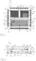
- Figure 1 illustrates a semiconductor package 10, whereby Figure 1a illustrates a top view and figure 1b a cross-sectional view of the semiconductor package 10.
- the semiconductor package 10 includes at least one die pad 11 and a plurality of outer contacts 12.
- the plurality of outer contacts 12 are arranged at the peripheral edges of all four sides 13 of the semiconductor package 10.
- the outer contacts 12 may have a different arrangement.
- outer contacts may be arranged on one side only or on two opposing sides of the package 10 or a single contact, for example an elongate contact, may be arranged on one side and a plurality of contacts arranged on one or more further sides of the package 10.
- the semiconductor package 10 includes a first semiconductor device 14 and a second semiconductor device 15.
- the semiconductor device 15 is arranged on the die pad 11.
- the first semiconductor device 14 may be arranged on a second die pad 16 which is spaced apart from the first die pad.
- the second semiconductor device 15 includes a front surface 21 and a rear surface 22.
- the front surface 21 of the second semiconductor device 15 faces towards the die pad 11 and the rear surface 22 faces away from the die pad 11.
- the second semiconductor device 15 includes a first transistor device 17 which includes a source electrode 18, a gate electrode 19 and a drain electrode 20.
- a front metallisation 23 is arranged on the front surface 21 and a rear metallisation 24 is arranged 24 arranged on the rear surface 22.
- the front metallisation 23 comprises a first power contact pad 25 which is coupled to the source electrode 18.
- the first power contact pad 25 is mounted on the die pad 11.
- the rear metallisation 24 includes a second power contact pad 26 which is electrically coupled to the drain electrode 20.
- the rear metallisation 24 further includes an auxiliary lateral redistribution structure 27 that is electrically insulated from the second power contact pad 26 and from the drain electrode 20.
- the first semiconductor device 14 is electrically coupled to the auxiliary lateral redistribution structure 27.
- the transistor device 17 is a vertical transistor device having a vertical drift path.
- the drain electrode 20 is formed by a drain region at the rear surface 22.
- the source electrode 18 and gate electrode 19 are formed at the opposing front surface 21.
- the transistor device 17 may be a MOSFET (Metal Oxide Semiconductor Field Effect Transistor) device, an insulated gate bipolar transistor (IGBT) device or a Bipolar Junction Transistor (BJT).
- MOSFET Metal Oxide Semiconductor Field Effect Transistor
- IGBT insulated gate bipolar transistor
- BJT Bipolar Junction Transistor
- the electrodes or terminals of the transistor device are referred to herein as source, drain and gate. As used herein, these terms also encompass the functionally equivalent terminals of other types of transistor devices, such as an insulated gate bipolar transistor (IGBT).
- IGBT insulated gate bipolar transistor
- the term “source” encompasses not only a source of a MOSFET device and of a superjunction device but also an emitter of an insulator gate bipolar transistor (IGBT) device and an emitter of a Bipolar Junction Transistor (BJT) device
- the term “drain” encompasses not only a drain of a MOSFET device or of a superjunction device but also a collector of an insulator gate bipolar transistor (IGBT) device and a collector of a BJT device
- the term “gate” encompasses not only a gate of a MOSFET device or of a superjunction device but also a gate of an insulator gate bipolar transistor (IGBT) device and a base of a
- the auxiliary lateral redistribution structure 27 which is arranged on the upwardly facing rear surface 22 of the second semiconductor device 15 is electrically unconnected and separate from the transistor device 17 of the second semiconductor device 15 and does not form part of the presently claimed invention.
- a portion of the rear surface 22 of the second semiconductor device 15 is used as part of a lateral redistribution structure that is internal to the package 10, for example as part of a lateral redistribution structure from the first semiconductor device 14 positioned at one corner of the package 10 to an outer contact 12' positioned in the opposing corner or diagonally opposing corner of the package 10.
- This arrangement provides flexibility in the redistribution patterns available within the package 10 and saves space within the package, for example space required by additional long connectors such as long bond wires.
- the auxiliary lateral redistribution structure 27 includes an elongate conductive trace 28 which extends in a peripheral edge region of the rear surface 22 that extends along two adjoining peripheral edges of the rear surface 22 of the semiconductor device 15.
- the conductive trace 28 extends into a contact pad 29, 30 at the two distal ends such that the contact pads 29, 30 are positioned in diagonally opposing corners of the rear surface 22 of the second semiconductor device 15.
- the first contact pad 29 is positioned laterally adjacent the first semiconductor device 14 so that the first semiconductor device 14 is electrically coupled to the first contact pad 29 by a relatively short electrical connector, such as a bond wire 31, extending between the first semiconductor device 14 and the contact pad 29 of the auxiliary lateral redistribution structure 27.
- the second contact pad 30 is electrically coupled to an outer contact 12' of the plurality of outer contacts 12 by an electrical connector such as a bond wire 32.
- the first semiconductor device 14 is electrically connected by means of the bond wire 31, the first contact pad 29, the conductive trace 28, the second contact pad 31 and the bond wire 32 to the outer contact 12' which is positioned at the opposing towards the opposing side of the semiconductor package 10.
- the auxiliary lateral redistribution structure 27 is electrically insulated from the transistor device 17 within the second semiconductor device 15, and is not part of the presently claimed invention, and is electrically insulated from the semiconductor device 15 and provides a lateral conductive redistribution structure.
- the auxiliary lateral redistribution structure 27 may be electrically insulated from the transistor device 17 within the second semiconductor device 15 and from the second power contact pad 26 by one or more electrically insulating layers 42 positioned between the rear surface 22 and the conductive layer providing the auxiliary lateral redistribution structure 27 and, optionally between the second power contact pad 26 and the conductive layer providing the auxiliary lateral redistribution structure 27.
- the semiconductor package 10 includes a third semiconductor device 33.
- the third semiconductor device 33 includes a transistor device 34.
- the third semiconductor device may be arranged on a third die pad 35 which is laterally spaced apart from the first die pad 16 and second die pad 11.
- the third die pad 35 is arranged laterally adjacent to the second die pad 16 with the second and third die pads 16, 35 being arranged adjacent a common side of the first die pad 11.
- the second tran sistor device 34 may be electrically coupled to the first transistor device 17 to form a half-bridge circuit.
- the second transistor device 34 may be arranged in the third semiconductor device 33 such that a third contact pad 36 connected to the source electrode is arranged on the upper surface and faces upwardly and a fourth power contact pad that is coupled to the drain electrode of the second transistor device 34 is arranged on the lower surface and is connected to the third die pad 35.
- the second power contact pad 26, which is laterally coupled to the drain electrode 20 of the first transistor device 17 also faces upwardly.
- the third power contact pad 36 of the second transistor device 33 may be electrically coupled to the second power contact pad 26 of the first transistor device 17 by one or more electrical connectors, such as a contact clip 37, which extends from the third power contact pad 36 to the second power contact pad 26 to form the half-bridge circuit.
- the contact clip 37 further extends to the outer contact 12" that is situated at the peripheral edge of the package 10 adjacent the first die pad 11 and on the opposing side of the second semiconductor device 15 to the third semiconductor device 33 and the first semiconductor device 14.
- the outer contact 12" provides the output node for the half bridge circuit.
- the first semiconductor device 14 includes gate driver circuitry for driving the gates of the first and second transistor devices 17, 34.
- further electrical connections between the first semiconductor device 14 and the gate pads 39, 40 of the second and third semiconductor devices 15, 33 are provided.
- the package 10 may also include a plastic molding 41 in which the semiconductor devices 14, 15, 33 and at least portions of the die pads 11, 16, 35 and portions of the outer contacts 12 are embedded.
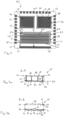
- Figure 2 illustrates a top view of a semiconductor package 50 according to an embodiment which is part of the presently clamed invention.
- the semiconductor package 50 includes a first semiconductor device 14 arranged on the second die pad 16, a second semiconductor device 15 arranged on the first die pad 11 and a third semiconductor device 33 arranged on the third die pad 35 similar to the embodiment illustrated in figure 1 .
- the first semiconductor device 14 may be an integrated circuit (IC) device and includes gate driver circuitry and the second semiconductor devices 15 includes a transistor device 17 and the third semiconductor device 33 may include a transistor device 34 similar to the embodiment illustrated in figure 1 .
- the semiconductor device 15' differs from the semiconductor device 15 illustrated in figure 1 in the arrangement of the front metallisation 23 arranged on the front surface 21 and the rear metallisation 24 arranged rear surface 22 of the second semiconductor device 15'.
- Figure 3a illustrates a cross-sectional view along the line A-A and figure 3b a cross-sectional view along the line B-B of the semiconductor device 15'.
- Figure 2 illustrating a top view looking down on the rear metallisation 24.
- the front metallisation 23 includes a first power contact pad 25 that is coupled to the source electrode 18 that is divided into at least two sections 52, 53, 54.
- the front metallisation 23 also includes one or more gate runners 51 which have a strip-like form and are arranged between and spaced apart from the sections 52, 53, 54 of the first power contact pad 25.
- a gate runner 51 is arranged between neighbouring sections 52, 53 and a further gate runner 51 is arranged between the neighbouring sections 53, 54 of the first power contact pad 25.
- the gate runners 51 extend along the entire length of the front surface 21 of the semiconductor device 15'.
- the first power contact pad 25 is divided into three substantially parallel strip-like portions 52, 53, 54 and four strip-like gate runners 51 are provided which are positioned between the sections 52, 53 and 53, 54 of the first power contact pad 25 and in the peripheral edge regions of the front surface 21 that are positioned adjacent the two opposing peripheral edges of the front surface 21.
- the gate runners 51 are not be connected to one another at the front surface 21.
- the rear metallisation structure 24 includes the second power contact pad 26 and an auxiliary lateral redistribution structure 27.
- the auxiliary lateral redistribution structure 27 includes an elongate conductive trace 28 that extends in the peripheral edge region of the rear surface 22 and along three adjoining sides towards the peripheral edge of the rear surface 22.
- the auxiliary lateral redistribution structure 27 is spaced apart and electrically insulated from the second power contact pad 26.
- the rear metallisation structure 27 also includes a contact pad 29 arranged in corner that is laterally adjacent the first transistor device 14 similar to the embodiment illustrated in figure 1 .
- the auxiliary lateral redistribution structure 27 on the rear surface 22 is electrically coupled to the gate runners 51 on the front surface 21 by one or more conductive vias 55 that extend through the semiconductor body of the second semiconductor device 15.
- a conductive via 55 is arranged at opposing ends of each of the gate runners 51 so that each end of the gate runners 51 is electrically coupled to the auxiliary lateral redistribution structure 27.
- the conductive vias 55 include conductive material, such as a metal, for example copper, or an alloy that is positioned in a via or through-hole that extends from the front surface 21 to the rear surface 22 and that is electrically insulated from the semiconductor body by one or more insulating layers lining the via.
- the gate runners 51 positioned on the front surface 21 are electrically coupled to one another at the rear surface 22 by the auxiliary lateral redistribution structure 27. Since the gate runners 51 of the front metallisation structure are electrically coupled to the auxiliary lateral redistribution structure 27 arranged on the rear surface 22 of the semiconductor device 15, the front metallisation structure 23 may not include a gate pad or a portion of the front metallisation structure 23 for the gate electrode which is exposed from insulating material.
- the gate runners 51 may be completely covered by insulating material 56 so that only the sections of the first power contact pad 25 are exposed from the insulating material and electrically connected to the underlying die pad 11.
- the third semiconductor device 33 also includes a second transistor device 34 and has an arrangement such that the third power contact pad 36 that is coupled to the source electrode faces upwards and is electrically coupled to the second power contact pad 26 that is coupled to the drain electrode 20 of the first transistor device 17 and one or more outer contacts 12 of the semiconductor package 50 in order to provide half bridge circuit.
- Figure 4 illustrates a top view of a semiconductor package 60 according to an embodiment which is part of the presently claimed invention.
- the semiconductor package 60 includes a first semiconductor device 14 arranged on the die pad 16, a second semiconductor device 15'' arranged on the die pad 11 and a third semiconductor device 33 arranged on third die pad 35 similar to the embodiment illustrated in figures 1 and 2 .
- the first semiconductor device 14 may be an integrated circuit device and includes gate driver circuitry and the second and third semiconductor devices 15'', 33 include each include a transistor device 17, 34.
- the semiconductor device 15'' differs from the semiconductor device 15' illustrated in figures 2 and 3 in the arrangement of the rear metallisation 24 arranged on the rear surface 22 of the second semiconductor device 15.
- Figure 5a illustrates a first cross-sectional view along the line C-C and figure 5b a cross-sectional view along the line D-D of the semiconductor device 15", with figure 4 illustrating a top view looking down on the rear metallisation structure 24.
- the front metallisation 23 includes a first power contact pad 25 coupled to the source electrode 18 that is divided into three strip-like portions 52, 53, 54 and four strip-like gate runners 51 which are positioned between and spaced apart from the three strip-like sections 52, 53, 54 of the first power contact pad 25.
- the rear metallisation structure 24 includes a second power contact pad 26 which is split into three sections 61, 62, 63 and an auxiliary lateral redistribution structure 27 that is spaced apart and electrically insulated from the second power contact pad 26 and the drain electrode 20.
- the auxiliary lateral redistribution structure 27 includes a first conductive trace 64 which is positioned in a peripheral edge region that extends along the peripheral edge of the rear surface 22 that is positioned adjacent the first semiconductor device 14 and the third semiconductor device 33.
- the conductive trace 64 extends into contact pad 29 which is positioned in the corner and electrically coupled to the first semiconductor device 14.
- the auxiliary lateral redistribution structure 27 includes two further conductive traces 65, 66 which extend perpendicularly to the first conductive trace 64 and across the width of the rear surface 22.
- the conductive traces 64, 65, 66 provide a redistribution structure for the gate electrode of the transistor device 17 that is positioned on the rear surface 22.
- the conductive traces 64, 65, 66 are spaced apart from and electrically insulated from the three sections 61, 62, 63 of the second power contact pad 26.
- One or more electrical insulating layers may be arranged between the each of conductive traces 64, 65, 66 and the three sections 61, 62, 63 of the second power contact pad 26.
- the gate runners 51 on the front surface 21 of the semiconductor device 50 are electrically connected to each of the conductive traces 65, 66 by a conductive via 67.
- the outermost gate runner 51 is electrically connected to the conductive trace 64 by conductive via 68 which may be positioned at the interface between the conductive trace 64 and the conductive traces 65, 66 as illustrated in figure 4 .
- each gate runner 51 is electrically coupled to the auxiliary lateral redistribution structure 27 by two conductive vias 67 positioned at different positions along the length of the gate runner 51.
- the conductive vias 67, 68 may be electrically insulated from the semiconductor body of the second semiconductor device 15" by one or more insulating layers lining the via in the second semiconductor device 15".
- the conductive trace 64 does not extend along the entire length of the peripheral edge of the transistor device 15" and may extend only to the second third conductive trace 66 from the contact pad 29. Whilst two perpendicular conductive traces 65, 66 are illustrated in figure 4 , one perpendicular conductive trace or three or more perpendicular conductive traces may be used. In some embodiments, the positions of the conductive vias 55, 67 and 68 may be combined so that each gate runner is electrically connected to a conductive trace of the auxiliary lateral redistribution structure 27 positioned on the rear surface at the opposing ends and intermediate the length of the gate runner.
- Each of the sections 61, 62, 53 of the second power contact pad 26 of the first transistor device 17 may be electrically coupled to the third power contact pad 36 of the third semiconductor device 33 and to one or more outer contacts 12" of the package 60 in order to form half bridge circuit and provide access to the node of the half bridge circuit.
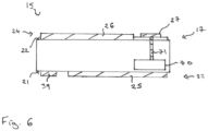
- the second semiconductor device 15 includes an auxiliary structure providing another function.
- Figure 6 illustrates a cross-sectional view of a second semiconductor device 15 which includes a transistor device 17 and an auxiliary structure 70.
- the auxiliary structure 70 is electrically coupled to the auxiliary lateral redistribution structure 27 on the rear surface 22 of the semiconductor device 15.
- the rear metallization 24 of the semiconductor device 15 includes a second power contact pad 26 on the upper surface 22 which is spaced apart and electrically insulated from the auxiliary lateral redistribution structure 27.
- the front metallisation 23 includes a gate metallisation 39 and a first power contact pad 25 on the front surface 21.
- the gate metallization 39 may include one or more runners 51 and the first power contact pad 25 may be split into two or more sections.
- the auxiliary structure 70 is electrically coupled to the auxiliary lateral redistribution structure 27 by one or more conductive vias 71.
- the auxiliary structure 70 is an auxiliary transistor device providing current sensing.
- the auxiliary lateral redistribution structure 27 is electrically coupled to the source electrode of the auxiliary transistor device in order to provide current sensing.
- the auxiliary structure 70 comprises an auxiliary transistor device providing temperature sensing.
- the auxiliary structure 70 is a pull-down transistor device.
- the auxiliary lateral redistribution structure 27 is electrically coupled to the gate electrode of the pull-down transistor device.
- the auxiliary lateral redistribution structure 27 includes two or more lateral redistribution structures that are electrically insulated from one another.
- the auxiliary lateral redistribution structure may include a first redistribution structure for the transistor device 17 and a second redistribution structure for the auxiliary device 70, whereby the first and second redistribution structures may be spaced apart from one another.
- Each of the lateral redistribution structures may be electrically coupled to the first device 14 and/or outer contacts 12 of the package.
- the semiconductor package according to any one of the embodiments described herein may be used in a SMPS (Switched Mode Power Supply) converter.
- switches typically MOSFETs or IGBTs
- SMPS converters switches, typically MOSFETs or IGBTs, are often arranged in a half-bridge configuration.
- the simplest one is the step-down converter ('buck'), which steps down voltage from its input to its output. At the same time, the current is stepped up to higher values than the supply current.
- the low-side switch of such a half-bridge is often flipped, i.e. it is mounted source-down.
- the second semiconductor device 15 of Figures 1 to 6 is an example of such a source-down arrangement.
- Such a configuration allows mounting the high-side and the low-side switches closer together which in turns helps minimize the overall parasitic loop inductance.
- Lower loop inductance enables faster switching and eventually boosts circuit efficiency.
- Such an assembly concept also optimizes the area usage in the package, ultimately leading to higher power density.
- MOSFETs As fast switching inevitably leads to higher rates of voltage and current change (dv/dt, di/dt), higher requirements are posed on the used switches, typically MOSFETs. MOSFETs need to turn-on and turn-off with minimized delay which is equivalent to homogenous transient behavior across the switch. Signal propagation times need to be as small as possible. This calls for low impedance routing of signal lines.
- the rear surface 22 of the semiconductor device 15 or chip backside is used as an additional redistribution layer.
- the chip may include a relatively thick backside metallization layer, typically 10 ⁇ m of copper.
- This metal layer can be lithographically structured creating two or more different regions. The main area is used for the drain power connection which requires a good electrical contact to the silicon substrate and the drain region of the transistor device. Other regions providing an auxiliary lateral redistribution structure, when used as signal lines, are electrically separated from the underlying silicon. This can be done by adding an isolation layer, for example a deposited oxide, beneath the metal area of the auxiliary lateral redistribution structure. Other isolation materials or stacks of materials may be used.
- lateral redistribution on the chip backside to route for example a signal from the left to the right side of a flipped chip, i.e. the chip backside is facing up, is provided.
- This may be used to avoid crossing wires or to keep a safe distance to other conductive elements, like clips, and the assembly in the package can be simplified. This adds flexibility in the package construction.
- the redistribution would not require any changes in the silicon substrate as the signal current flows only on the surface of the chip within the auxiliary lateral redistribution structure.
- the auxiliary lateral redistribution structure provides routing for a signal from the chip backside to the front side. This is beneficial if the aforementioned complexity of the chip makes routing on the chip front side difficult or the area consumption is significant. As there are usually less layout constraints on the chip backside, a low-impedance connection may be formed by the thick metallization layer.
- Figures 2 to 5 illustrate an example where the gate signal is redistributed to all corners of the chip.
- a significantly better connection can be achieved.
- a chip having a size of 4 mm x 1.25 mm with two center gate buses, for example the gate runners 51, and corner connections (similar to the one shown in Figures 2 and 4 ) has a total effective gate resistance of 699 mOhm when 8 ⁇ m wide and 3.2 ⁇ m AlCu runners are used. From this 699 mOhm, only 196 mOhm are due to the resistivity of the buried gate poly lines, the remainder of 503 mOhm is due to the metal runners.
- the overall effective gate resistance may be reduced to just 375 mOhm, which means that the metal contribution has been reduced to just 178 mOhm, about a third of the original value.
- wider backside runners e.g. the width of the conductive traces 28, 64, 65, 66 may be increased, the theoretical limit of a quarter will be approached for the given chip topology. Reducing the metal gate resistance becomes particularly important if the gate poly lines are replaced by other materials or material combinations, for example tungsten, as the relative contribution of the metal runners becomes bigger.
- one or more backside metal runners extends into the chip center.
- Such an approach together with a clip connection to drain, requires typically local backside passivation in order to avoid solder bridging. Routing a signal to the center of the die is particularly useful if a certain potential needs to be tapped, or if a structure needs to be attached to multiples of gate fingers.
- An example for this are 'pull-down'-FETs, i.e. isolated MOSFETs which make sure that the gate remains at source potential in off-state during fast transients, i.e. to avoid unwanted turn-on due to displacement currents.
- FIG 6 An example is illustrated in figure 6 .
- Such auxiliary transistors require the gate potential (present at the front side gate buses), the source potential (available almost everywhere on the chip frontside), and a GATE# signal, which is more or less the inverted gate signal and needs to be supplied from a driver IC.
- these 'pull-down'-FETs are located at the gate buses and their gates are controlled from the chip backside using conductive vias. There is a multitude of such 'pull-down'-transistors to properly short the gate and source everywhere.
- a passivation layer may be used on top of the redistribution layer. Passivation could be created using, for example, epoxy or imide.
- Figure 6 illustrates an example with ⁇ pull-down'-FETs distributed over the chip.
- the 'pull-down'-FETs get their gate signal (GATE#) through silicon-through-vias from the chip backside where a metal runner is routed to a pad connected to the gate driver.
Landscapes
- Insulated Gate Type Field-Effect Transistor (AREA)
Claims (7)
- Halbleitergehäuse (10; 50; 60), umfassend:mindestens ein Diepad (11);eine Mehrzahl äußerer Kontakte (12);ein erstes Halbleiterbauelement (14);ein zweites Halbleiterbauelement (15; 15'; 15"), das lateral neben dem ersten Halbleiterbauelement (14) angeordnet ist, wobei das zweite Halbleiterbauelement (15; 15', 15") ein erstes Transistorbauelement (17) mit einer Source-Elektrode (18), einer Gate-Elektrode (19) und einer Drain-Elektrode (20) umfasst, wobei das zweite Halbleiterbauelement (15; 15'; 15") eine vordere Fläche (21) und eine hintere Fläche (22), eine vordere Metallisierung (23) auf der vorderen Fläche (21) und eine hintere Metallisierung (24) auf der hinteren Fläche (22) umfasst, wobei die vordere Metallisierung (23) ein erstes Leistungskontaktpad (25) umfasst, das mit der Source-Elektrode (18) verbunden ist, wobei das erste Leistungskontaktpad (25) auf dem Diepad (11) montiert ist, und die hintere Metallisierung (24) ein zweites Leistungskontaktpad (26) auf der hinteren Fläche (22), das elektrisch mit der Drain-Elektrode (20) verbunden ist, und eine laterale Hilfsumverteilungsstruktur (27), die auf der hinteren Fläche (22) lateral neben dem zweiten Leistungskontaktpad (26) angeordnet ist und von dem zweiten Leistungskontaktpad und der Drain-Elektrode (20) elektrisch isoliert ist, umfasst,wobei das erste Halbleiterbauelement (14) über die laterale Hilfsumverteilungsstruktur auf dem zweiten Halbleiterbauelement (15) elektrisch mit der lateralen Hilfsumverteilungsstruktur (27) und mit einem Außenkontakt (12') verbunden ist, wobei die laterale Hilfsumverteilungsstruktur eine Leiterbahn (28; 64) umfasst, die sich an einem oder zwei Enden der Leiterbahn (28; 64) in ein Kontaktpad (29, 30) erstreckt,dadurch gekennzeichnet, dassdas erste Halbleiterbauelement (14) eine Gate-Treiberschaltung umfasst und über die laterale Hilfsumverteilungsstruktur (27) elektrisch mit der Gate-Elektrode (19) des ersten Transistorbauelements (17) verbunden ist,und dass das zweite Halbleiterbauelement (15'; 15") ferner mindestens eine Substratdurchkontaktierung (55, 67, 68) umfasst, die sich von der hinteren Fläche (22) zu der vorderen Fläche (21) erstreckt, wobei die Substratdurchkontaktierung (55, 67, 68) elektrisch mit der lateralen Hilfsumverteilungsstruktur (17) auf der hinteren Fläche (22) verbunden sind.
- Halbleitergehäuse (50, 60) nach Anspruch 1, wobei die Substratdurchkontaktierung (55, 67, 67) ferner elektrisch mit einem Gate-Läufer (51) auf der vorderen Fläche (21) verbunden ist, der elektrisch mit der Gate-Elektrode (19) des ersten Transistorbauelements (17) verbunden ist.
- Halbleitergehäuse nach Anspruch 1 oder Anspruch 2, wobei die zweite Halbleiterkomponente (15) ferner eine Hilfsstruktur (70) umfasst und die laterale Hilfsumverteilungsstruktur (17) elektrisch mit der Hilfsstruktur (70) verbunden ist.
- Halbleitergehäuse nach Anspruch 3, wobei es sich bei der Hilfsstruktur (70) um eine Hilfstransistorvorrichtung, die eine Strommessung ermöglicht, oder eine Hilfstransistorvorrichtung, die eine Temperaturmessung ermöglicht, oder eine Pull-Down-Hilfstransistorvorrichtung handelt.
- Halbleitergehäuse (60) nach einem der Ansprüche 1 bis 4, wobei das zweite Leistungskontaktpad (26) auf der hinteren Fläche (22) in zwei oder mehr Abschnitte (61; 62; 63) aufgeteilt ist, und wobei die laterale Hilfsumverteilungsstruktur (27) eine erste Leiterbahn (65), die zwischen zwei benachbarten Abschnitten (61; 62) des zweiten Leistungskontaktpads positioniert ist und von diesen elektrisch isoliert ist, und eine zweite Leiterbahn (64), die in einem Umfangsrandbereich der hinteren Fläche (22) angeordnet ist und mit der ersten Leiterbahn (64) verbunden ist, umfasst, wobei die Substratdurchkontaktierung (67) zwischen der ersten Leiterbahn (64) auf der hinteren Fläche (22) und dem Gate-Läufer (51) auf der vorderen Fläche (21) oder zwischen der zweiten Leiterbahn (64) auf der hinteren Fläche (22) und dem Gate-Läufer (51) auf der vorderen Fläche (21) verläuft.
- Halbleitergehäuse (60) nach Anspruch 5, wobei sich der Gate-Läufer (51) auf der vorderen Fläche (21) im Wesentlichen senkrecht zu der ersten Leiterbahn (65) auf der hinteren Fläche (22) erstreckt und die Substratdurchkontaktierung (67) sich zwischen der ersten Leiterbahn (64) und dem Gate-Läufer (51) erstreckt.
- Halbleitergehäuse (10; 50; 60) nach einem der Ansprüche 1 bis 6, ferner umfassend ein drittes Halbleiterbauelement (33), das ein zweites Transistorbauelement (34) umfasst, wobei das erste und das zweite Transistorbauelement (17, 34) zu einer Halbbrücke verbunden sind und das erste Halbleiterbauelement (14) eine Gate-Treiberschaltung umfasst.
Priority Applications (3)
| Application Number | Priority Date | Filing Date | Title |
|---|---|---|---|
| EP19159762.4A EP3703123B1 (de) | 2019-02-27 | 2019-02-27 | Halbleiterbauelement und halbleitergehäuse |
| US16/801,646 US11158569B2 (en) | 2019-02-27 | 2020-02-26 | Semiconductor component and semiconductor package |
| CN202010123545.7A CN111627879B (zh) | 2019-02-27 | 2020-02-27 | 半导体组件及半导体封装 |
Applications Claiming Priority (1)
| Application Number | Priority Date | Filing Date | Title |
|---|---|---|---|
| EP19159762.4A EP3703123B1 (de) | 2019-02-27 | 2019-02-27 | Halbleiterbauelement und halbleitergehäuse |
Publications (2)
| Publication Number | Publication Date |
|---|---|
| EP3703123A1 EP3703123A1 (de) | 2020-09-02 |
| EP3703123B1 true EP3703123B1 (de) | 2024-08-14 |
Family
ID=65635455
Family Applications (1)
| Application Number | Title | Priority Date | Filing Date |
|---|---|---|---|
| EP19159762.4A Active EP3703123B1 (de) | 2019-02-27 | 2019-02-27 | Halbleiterbauelement und halbleitergehäuse |
Country Status (3)
| Country | Link |
|---|---|
| US (1) | US11158569B2 (de) |
| EP (1) | EP3703123B1 (de) |
| CN (1) | CN111627879B (de) |
Families Citing this family (3)
| Publication number | Priority date | Publication date | Assignee | Title |
|---|---|---|---|---|
| EP3975225A1 (de) * | 2020-09-24 | 2022-03-30 | Infineon Technologies Austria AG | Halbleitermodul |
| US11978723B2 (en) * | 2021-03-31 | 2024-05-07 | Taiwan Semiconductor Manufacturing Company, Ltd. | Vertical interconnect structures in three-dimensional integrated circuits |
| DE102022208031A1 (de) | 2022-08-03 | 2024-02-08 | Siemens Aktiengesellschaft | Halbleiterbauelement |
Family Cites Families (9)
| Publication number | Priority date | Publication date | Assignee | Title |
|---|---|---|---|---|
| JPH07193186A (ja) * | 1993-12-27 | 1995-07-28 | Toshiba Corp | 半導体装置 |
| JP3646970B2 (ja) * | 1998-05-27 | 2005-05-11 | 松下電器産業株式会社 | 半導体集積回路及び半導体集積回路装置 |
| DE102005055761B4 (de) * | 2005-11-21 | 2008-02-07 | Infineon Technologies Ag | Leistungshalbleiterbauelement mit Halbleiterchipstapel in Brückenschaltung und Verfahren zur Herstellung desselben |
| JP4916745B2 (ja) * | 2006-03-28 | 2012-04-18 | ルネサスエレクトロニクス株式会社 | 半導体装置の製造方法 |
| JP5107839B2 (ja) * | 2008-09-10 | 2012-12-26 | ルネサスエレクトロニクス株式会社 | 半導体装置 |
| US8362606B2 (en) * | 2010-07-29 | 2013-01-29 | Alpha & Omega Semiconductor, Inc. | Wafer level chip scale package |
| US8587101B2 (en) | 2010-12-13 | 2013-11-19 | International Rectifier Corporation | Multi-chip module (MCM) power quad flat no-lead (PQFN) semiconductor package utilizing a leadframe for electrical interconnections |
| US9054040B2 (en) * | 2013-02-27 | 2015-06-09 | Infineon Technologies Austria Ag | Multi-die package with separate inter-die interconnects |
| US9385070B2 (en) * | 2013-06-28 | 2016-07-05 | Delta Electronics, Inc. | Semiconductor component having a lateral semiconductor device and a vertical semiconductor device |
-
2019
- 2019-02-27 EP EP19159762.4A patent/EP3703123B1/de active Active
-
2020
- 2020-02-26 US US16/801,646 patent/US11158569B2/en active Active
- 2020-02-27 CN CN202010123545.7A patent/CN111627879B/zh active Active
Also Published As
| Publication number | Publication date |
|---|---|
| US11158569B2 (en) | 2021-10-26 |
| EP3703123A1 (de) | 2020-09-02 |
| US20200273788A1 (en) | 2020-08-27 |
| CN111627879B (zh) | 2025-09-09 |
| CN111627879A (zh) | 2020-09-04 |
Similar Documents
| Publication | Publication Date | Title |
|---|---|---|
| JP5550553B2 (ja) | 電力用半導体モジュール | |
| US12027449B2 (en) | Device topologies for high current lateral power semiconductor devices | |
| CN103051312B (zh) | 低阻抗栅极控制方法和设备 | |
| US10049968B2 (en) | Semiconductor device | |
| EP3442020B1 (de) | Leistungshalbleitermodul | |
| US20250379124A1 (en) | Power circuit module | |
| EP2862202B1 (de) | Substrat zur montage mehrerer leistungstransistoren darauf und leistungshalbleitermodul | |
| KR102063101B1 (ko) | 균일하게 분배된 전류 흐름을 위한 리드 프레임 상의 인터디지트 디바이스 | |
| JP2020517125A (ja) | 一体型クランプ回路を有するパワーモジュールおよびそのプロセス | |
| EP0987762B1 (de) | Halbleitermodul | |
| US11652473B2 (en) | Power modules having an integrated clamp circuit and process thereof | |
| US11158569B2 (en) | Semiconductor component and semiconductor package | |
| JP2002153079A (ja) | 半導体装置 | |
| CN114944379B (zh) | 具有内插器的半导体封装和无源元件 | |
| CN119581448A (zh) | 封装体及制造封装体的方法 | |
| CN114300435A (zh) | 半导体模块 | |
| US8169088B2 (en) | Power converter integrated circuit floor plan and package | |
| US11133303B2 (en) | Semiconductor device and semiconductor arrangement comprising semiconductor devices | |
| EP3975244A1 (de) | Halbleitergehäuse und verfahren zur herstellung eines halbleitergehäuses | |
| US20240363497A1 (en) | Semiconductor module arrangements | |
| JP2024533525A (ja) | ブリッジ接続クラスd-rf増幅器回路 | |
| HK1234204A1 (en) | Semiconductor device |
Legal Events
| Date | Code | Title | Description |
|---|---|---|---|
| PUAI | Public reference made under article 153(3) epc to a published international application that has entered the european phase |
Free format text: ORIGINAL CODE: 0009012 |
|
| STAA | Information on the status of an ep patent application or granted ep patent |
Free format text: STATUS: THE APPLICATION HAS BEEN PUBLISHED |
|
| AK | Designated contracting states |
Kind code of ref document: A1 Designated state(s): AL AT BE BG CH CY CZ DE DK EE ES FI FR GB GR HR HU IE IS IT LI LT LU LV MC MK MT NL NO PL PT RO RS SE SI SK SM TR |
|
| AX | Request for extension of the european patent |
Extension state: BA ME |
|
| STAA | Information on the status of an ep patent application or granted ep patent |
Free format text: STATUS: REQUEST FOR EXAMINATION WAS MADE |
|
| 17P | Request for examination filed |
Effective date: 20210302 |
|
| RBV | Designated contracting states (corrected) |
Designated state(s): AL AT BE BG CH CY CZ DE DK EE ES FI FR GB GR HR HU IE IS IT LI LT LU LV MC MK MT NL NO PL PT RO RS SE SI SK SM TR |
|
| STAA | Information on the status of an ep patent application or granted ep patent |
Free format text: STATUS: EXAMINATION IS IN PROGRESS |
|
| 17Q | First examination report despatched |
Effective date: 20210423 |
|
| GRAP | Despatch of communication of intention to grant a patent |
Free format text: ORIGINAL CODE: EPIDOSNIGR1 |
|
| STAA | Information on the status of an ep patent application or granted ep patent |
Free format text: STATUS: GRANT OF PATENT IS INTENDED |
|
| INTG | Intention to grant announced |
Effective date: 20240306 |
|
| P01 | Opt-out of the competence of the unified patent court (upc) registered |
Effective date: 20240415 |
|
| GRAS | Grant fee paid |
Free format text: ORIGINAL CODE: EPIDOSNIGR3 |
|
| GRAA | (expected) grant |
Free format text: ORIGINAL CODE: 0009210 |
|
| STAA | Information on the status of an ep patent application or granted ep patent |
Free format text: STATUS: THE PATENT HAS BEEN GRANTED |
|
| AK | Designated contracting states |
Kind code of ref document: B1 Designated state(s): AL AT BE BG CH CY CZ DE DK EE ES FI FR GB GR HR HU IE IS IT LI LT LU LV MC MK MT NL NO PL PT RO RS SE SI SK SM TR |
|
| REG | Reference to a national code |
Ref country code: GB Ref legal event code: FG4D |
|
| REG | Reference to a national code |
Ref country code: CH Ref legal event code: EP |
|
| REG | Reference to a national code |
Ref country code: DE Ref legal event code: R096 Ref document number: 602019056878 Country of ref document: DE |
|
| REG | Reference to a national code |
Ref country code: IE Ref legal event code: FG4D |
|
| REG | Reference to a national code |
Ref country code: LT Ref legal event code: MG9D |
|
| REG | Reference to a national code |
Ref country code: NL Ref legal event code: MP Effective date: 20240814 |
|
| PG25 | Lapsed in a contracting state [announced via postgrant information from national office to epo] |
Ref country code: NO Free format text: LAPSE BECAUSE OF FAILURE TO SUBMIT A TRANSLATION OF THE DESCRIPTION OR TO PAY THE FEE WITHIN THE PRESCRIBED TIME-LIMIT Effective date: 20241114 |
|
| REG | Reference to a national code |
Ref country code: AT Ref legal event code: MK05 Ref document number: 1714117 Country of ref document: AT Kind code of ref document: T Effective date: 20240814 |
|
| PG25 | Lapsed in a contracting state [announced via postgrant information from national office to epo] |
Ref country code: PT Free format text: LAPSE BECAUSE OF FAILURE TO SUBMIT A TRANSLATION OF THE DESCRIPTION OR TO PAY THE FEE WITHIN THE PRESCRIBED TIME-LIMIT Effective date: 20241216 Ref country code: NL Free format text: LAPSE BECAUSE OF FAILURE TO SUBMIT A TRANSLATION OF THE DESCRIPTION OR TO PAY THE FEE WITHIN THE PRESCRIBED TIME-LIMIT Effective date: 20240814 Ref country code: GR Free format text: LAPSE BECAUSE OF FAILURE TO SUBMIT A TRANSLATION OF THE DESCRIPTION OR TO PAY THE FEE WITHIN THE PRESCRIBED TIME-LIMIT Effective date: 20241115 Ref country code: PL Free format text: LAPSE BECAUSE OF FAILURE TO SUBMIT A TRANSLATION OF THE DESCRIPTION OR TO PAY THE FEE WITHIN THE PRESCRIBED TIME-LIMIT Effective date: 20240814 Ref country code: FI Free format text: LAPSE BECAUSE OF FAILURE TO SUBMIT A TRANSLATION OF THE DESCRIPTION OR TO PAY THE FEE WITHIN THE PRESCRIBED TIME-LIMIT Effective date: 20240814 |
|
| PG25 | Lapsed in a contracting state [announced via postgrant information from national office to epo] |
Ref country code: BG Free format text: LAPSE BECAUSE OF FAILURE TO SUBMIT A TRANSLATION OF THE DESCRIPTION OR TO PAY THE FEE WITHIN THE PRESCRIBED TIME-LIMIT Effective date: 20240814 |
|
| PG25 | Lapsed in a contracting state [announced via postgrant information from national office to epo] |
Ref country code: LV Free format text: LAPSE BECAUSE OF FAILURE TO SUBMIT A TRANSLATION OF THE DESCRIPTION OR TO PAY THE FEE WITHIN THE PRESCRIBED TIME-LIMIT Effective date: 20240814 |
|
| PG25 | Lapsed in a contracting state [announced via postgrant information from national office to epo] |
Ref country code: AT Free format text: LAPSE BECAUSE OF FAILURE TO SUBMIT A TRANSLATION OF THE DESCRIPTION OR TO PAY THE FEE WITHIN THE PRESCRIBED TIME-LIMIT Effective date: 20240814 Ref country code: IS Free format text: LAPSE BECAUSE OF FAILURE TO SUBMIT A TRANSLATION OF THE DESCRIPTION OR TO PAY THE FEE WITHIN THE PRESCRIBED TIME-LIMIT Effective date: 20241214 |
|
| PG25 | Lapsed in a contracting state [announced via postgrant information from national office to epo] |
Ref country code: HR Free format text: LAPSE BECAUSE OF FAILURE TO SUBMIT A TRANSLATION OF THE DESCRIPTION OR TO PAY THE FEE WITHIN THE PRESCRIBED TIME-LIMIT Effective date: 20240814 |
|
| PG25 | Lapsed in a contracting state [announced via postgrant information from national office to epo] |
Ref country code: RS Free format text: LAPSE BECAUSE OF FAILURE TO SUBMIT A TRANSLATION OF THE DESCRIPTION OR TO PAY THE FEE WITHIN THE PRESCRIBED TIME-LIMIT Effective date: 20241114 Ref country code: ES Free format text: LAPSE BECAUSE OF FAILURE TO SUBMIT A TRANSLATION OF THE DESCRIPTION OR TO PAY THE FEE WITHIN THE PRESCRIBED TIME-LIMIT Effective date: 20240814 |
|
| PG25 | Lapsed in a contracting state [announced via postgrant information from national office to epo] |
Ref country code: RS Free format text: LAPSE BECAUSE OF FAILURE TO SUBMIT A TRANSLATION OF THE DESCRIPTION OR TO PAY THE FEE WITHIN THE PRESCRIBED TIME-LIMIT Effective date: 20241114 Ref country code: PT Free format text: LAPSE BECAUSE OF FAILURE TO SUBMIT A TRANSLATION OF THE DESCRIPTION OR TO PAY THE FEE WITHIN THE PRESCRIBED TIME-LIMIT Effective date: 20241216 Ref country code: PL Free format text: LAPSE BECAUSE OF FAILURE TO SUBMIT A TRANSLATION OF THE DESCRIPTION OR TO PAY THE FEE WITHIN THE PRESCRIBED TIME-LIMIT Effective date: 20240814 Ref country code: NO Free format text: LAPSE BECAUSE OF FAILURE TO SUBMIT A TRANSLATION OF THE DESCRIPTION OR TO PAY THE FEE WITHIN THE PRESCRIBED TIME-LIMIT Effective date: 20241114 Ref country code: NL Free format text: LAPSE BECAUSE OF FAILURE TO SUBMIT A TRANSLATION OF THE DESCRIPTION OR TO PAY THE FEE WITHIN THE PRESCRIBED TIME-LIMIT Effective date: 20240814 Ref country code: LV Free format text: LAPSE BECAUSE OF FAILURE TO SUBMIT A TRANSLATION OF THE DESCRIPTION OR TO PAY THE FEE WITHIN THE PRESCRIBED TIME-LIMIT Effective date: 20240814 Ref country code: IS Free format text: LAPSE BECAUSE OF FAILURE TO SUBMIT A TRANSLATION OF THE DESCRIPTION OR TO PAY THE FEE WITHIN THE PRESCRIBED TIME-LIMIT Effective date: 20241214 Ref country code: HR Free format text: LAPSE BECAUSE OF FAILURE TO SUBMIT A TRANSLATION OF THE DESCRIPTION OR TO PAY THE FEE WITHIN THE PRESCRIBED TIME-LIMIT Effective date: 20240814 Ref country code: GR Free format text: LAPSE BECAUSE OF FAILURE TO SUBMIT A TRANSLATION OF THE DESCRIPTION OR TO PAY THE FEE WITHIN THE PRESCRIBED TIME-LIMIT Effective date: 20241115 Ref country code: FI Free format text: LAPSE BECAUSE OF FAILURE TO SUBMIT A TRANSLATION OF THE DESCRIPTION OR TO PAY THE FEE WITHIN THE PRESCRIBED TIME-LIMIT Effective date: 20240814 Ref country code: ES Free format text: LAPSE BECAUSE OF FAILURE TO SUBMIT A TRANSLATION OF THE DESCRIPTION OR TO PAY THE FEE WITHIN THE PRESCRIBED TIME-LIMIT Effective date: 20240814 Ref country code: BG Free format text: LAPSE BECAUSE OF FAILURE TO SUBMIT A TRANSLATION OF THE DESCRIPTION OR TO PAY THE FEE WITHIN THE PRESCRIBED TIME-LIMIT Effective date: 20240814 Ref country code: AT Free format text: LAPSE BECAUSE OF FAILURE TO SUBMIT A TRANSLATION OF THE DESCRIPTION OR TO PAY THE FEE WITHIN THE PRESCRIBED TIME-LIMIT Effective date: 20240814 |
|
| PG25 | Lapsed in a contracting state [announced via postgrant information from national office to epo] |
Ref country code: DK Free format text: LAPSE BECAUSE OF FAILURE TO SUBMIT A TRANSLATION OF THE DESCRIPTION OR TO PAY THE FEE WITHIN THE PRESCRIBED TIME-LIMIT Effective date: 20240814 Ref country code: SM Free format text: LAPSE BECAUSE OF FAILURE TO SUBMIT A TRANSLATION OF THE DESCRIPTION OR TO PAY THE FEE WITHIN THE PRESCRIBED TIME-LIMIT Effective date: 20240814 Ref country code: RO Free format text: LAPSE BECAUSE OF FAILURE TO SUBMIT A TRANSLATION OF THE DESCRIPTION OR TO PAY THE FEE WITHIN THE PRESCRIBED TIME-LIMIT Effective date: 20240814 |
|
| PG25 | Lapsed in a contracting state [announced via postgrant information from national office to epo] |
Ref country code: EE Free format text: LAPSE BECAUSE OF FAILURE TO SUBMIT A TRANSLATION OF THE DESCRIPTION OR TO PAY THE FEE WITHIN THE PRESCRIBED TIME-LIMIT Effective date: 20240814 |
|
| PG25 | Lapsed in a contracting state [announced via postgrant information from national office to epo] |
Ref country code: CZ Free format text: LAPSE BECAUSE OF FAILURE TO SUBMIT A TRANSLATION OF THE DESCRIPTION OR TO PAY THE FEE WITHIN THE PRESCRIBED TIME-LIMIT Effective date: 20240814 |
|
| PG25 | Lapsed in a contracting state [announced via postgrant information from national office to epo] |
Ref country code: SK Free format text: LAPSE BECAUSE OF FAILURE TO SUBMIT A TRANSLATION OF THE DESCRIPTION OR TO PAY THE FEE WITHIN THE PRESCRIBED TIME-LIMIT Effective date: 20240814 Ref country code: IT Free format text: LAPSE BECAUSE OF FAILURE TO SUBMIT A TRANSLATION OF THE DESCRIPTION OR TO PAY THE FEE WITHIN THE PRESCRIBED TIME-LIMIT Effective date: 20240814 |
|
| REG | Reference to a national code |
Ref country code: DE Ref legal event code: R097 Ref document number: 602019056878 Country of ref document: DE |
|
| PLBE | No opposition filed within time limit |
Free format text: ORIGINAL CODE: 0009261 |
|
| STAA | Information on the status of an ep patent application or granted ep patent |
Free format text: STATUS: NO OPPOSITION FILED WITHIN TIME LIMIT |
|
| PGFP | Annual fee paid to national office [announced via postgrant information from national office to epo] |
Ref country code: DE Payment date: 20250422 Year of fee payment: 7 |
|
| 26N | No opposition filed |
Effective date: 20250515 |
|
| PG25 | Lapsed in a contracting state [announced via postgrant information from national office to epo] |
Ref country code: SE Free format text: LAPSE BECAUSE OF FAILURE TO SUBMIT A TRANSLATION OF THE DESCRIPTION OR TO PAY THE FEE WITHIN THE PRESCRIBED TIME-LIMIT Effective date: 20240814 |
|
| PG25 | Lapsed in a contracting state [announced via postgrant information from national office to epo] |
Ref country code: MC Free format text: LAPSE BECAUSE OF FAILURE TO SUBMIT A TRANSLATION OF THE DESCRIPTION OR TO PAY THE FEE WITHIN THE PRESCRIBED TIME-LIMIT Effective date: 20240814 |
|
| REG | Reference to a national code |
Ref country code: CH Ref legal event code: PL |
|
| PG25 | Lapsed in a contracting state [announced via postgrant information from national office to epo] |
Ref country code: LU Free format text: LAPSE BECAUSE OF NON-PAYMENT OF DUE FEES Effective date: 20250227 |
|
| PG25 | Lapsed in a contracting state [announced via postgrant information from national office to epo] |
Ref country code: CH Free format text: LAPSE BECAUSE OF NON-PAYMENT OF DUE FEES Effective date: 20250228 |
|
| GBPC | Gb: european patent ceased through non-payment of renewal fee |
Effective date: 20250227 |
|
| REG | Reference to a national code |
Ref country code: DE Ref legal event code: R079 Ref document number: 602019056878 Country of ref document: DE Free format text: PREVIOUS MAIN CLASS: H01L0023495000 Ipc: H10W0070400000 |
|
| REG | Reference to a national code |
Ref country code: BE Ref legal event code: MM Effective date: 20250228 |
|
| PG25 | Lapsed in a contracting state [announced via postgrant information from national office to epo] |
Ref country code: GB Free format text: LAPSE BECAUSE OF NON-PAYMENT OF DUE FEES Effective date: 20250227 |
|
| PG25 | Lapsed in a contracting state [announced via postgrant information from national office to epo] |
Ref country code: FR Free format text: LAPSE BECAUSE OF NON-PAYMENT OF DUE FEES Effective date: 20250228 |
|
| PG25 | Lapsed in a contracting state [announced via postgrant information from national office to epo] |
Ref country code: BE Free format text: LAPSE BECAUSE OF NON-PAYMENT OF DUE FEES Effective date: 20250228 |
|
| PG25 | Lapsed in a contracting state [announced via postgrant information from national office to epo] |
Ref country code: IE Free format text: LAPSE BECAUSE OF NON-PAYMENT OF DUE FEES Effective date: 20250227 |