EP3703040B1 - Anzeigestützenspleissvorrichtung - Google Patents
Anzeigestützenspleissvorrichtung Download PDFInfo
- Publication number
- EP3703040B1 EP3703040B1 EP19176836.5A EP19176836A EP3703040B1 EP 3703040 B1 EP3703040 B1 EP 3703040B1 EP 19176836 A EP19176836 A EP 19176836A EP 3703040 B1 EP3703040 B1 EP 3703040B1
- Authority
- EP
- European Patent Office
- Prior art keywords
- display
- bodies
- mounting site
- mounting
- magnet
- Prior art date
- Legal status (The legal status is an assumption and is not a legal conclusion. Google has not performed a legal analysis and makes no representation as to the accuracy of the status listed.)
- Active
Links
Images


Classifications
-
- G—PHYSICS
- G09—EDUCATION; CRYPTOGRAPHY; DISPLAY; ADVERTISING; SEALS
- G09F—DISPLAYING; ADVERTISING; SIGNS; LABELS OR NAME-PLATES; SEALS
- G09F13/00—Illuminated signs; Luminous advertising
- G09F13/04—Signs, boards or panels, illuminated from behind the insignia
- G09F13/0404—Signs, boards or panels, illuminated from behind the insignia the light source being enclosed in a box forming the character of the sign
-
- G—PHYSICS
- G09—EDUCATION; CRYPTOGRAPHY; DISPLAY; ADVERTISING; SEALS
- G09F—DISPLAYING; ADVERTISING; SIGNS; LABELS OR NAME-PLATES; SEALS
- G09F13/00—Illuminated signs; Luminous advertising
- G09F13/04—Signs, boards or panels, illuminated from behind the insignia
-
- G—PHYSICS
- G09—EDUCATION; CRYPTOGRAPHY; DISPLAY; ADVERTISING; SEALS
- G09F—DISPLAYING; ADVERTISING; SIGNS; LABELS OR NAME-PLATES; SEALS
- G09F13/00—Illuminated signs; Luminous advertising
- G09F13/04—Signs, boards or panels, illuminated from behind the insignia
- G09F13/0413—Frames or casing structures therefor
-
- F—MECHANICAL ENGINEERING; LIGHTING; HEATING; WEAPONS; BLASTING
- F21—LIGHTING
- F21V—FUNCTIONAL FEATURES OR DETAILS OF LIGHTING DEVICES OR SYSTEMS THEREOF; STRUCTURAL COMBINATIONS OF LIGHTING DEVICES WITH OTHER ARTICLES, NOT OTHERWISE PROVIDED FOR
- F21V23/00—Arrangement of electric circuit elements in or on lighting devices
- F21V23/001—Arrangement of electric circuit elements in or on lighting devices the elements being electrical wires or cables
-
- F—MECHANICAL ENGINEERING; LIGHTING; HEATING; WEAPONS; BLASTING
- F21—LIGHTING
- F21V—FUNCTIONAL FEATURES OR DETAILS OF LIGHTING DEVICES OR SYSTEMS THEREOF; STRUCTURAL COMBINATIONS OF LIGHTING DEVICES WITH OTHER ARTICLES, NOT OTHERWISE PROVIDED FOR
- F21V23/00—Arrangement of electric circuit elements in or on lighting devices
- F21V23/06—Arrangement of electric circuit elements in or on lighting devices the elements being coupling devices, e.g. connectors
-
- F—MECHANICAL ENGINEERING; LIGHTING; HEATING; WEAPONS; BLASTING
- F21—LIGHTING
- F21V—FUNCTIONAL FEATURES OR DETAILS OF LIGHTING DEVICES OR SYSTEMS THEREOF; STRUCTURAL COMBINATIONS OF LIGHTING DEVICES WITH OTHER ARTICLES, NOT OTHERWISE PROVIDED FOR
- F21V3/00—Globes; Bowls; Cover glasses
-
- G—PHYSICS
- G09—EDUCATION; CRYPTOGRAPHY; DISPLAY; ADVERTISING; SEALS
- G09F—DISPLAYING; ADVERTISING; SIGNS; LABELS OR NAME-PLATES; SEALS
- G09F13/00—Illuminated signs; Luminous advertising
- G09F13/04—Signs, boards or panels, illuminated from behind the insignia
- G09F13/0409—Arrangements for homogeneous illumination of the display surface, e.g. using a layer having a non-uniform transparency
-
- G—PHYSICS
- G09—EDUCATION; CRYPTOGRAPHY; DISPLAY; ADVERTISING; SEALS
- G09F—DISPLAYING; ADVERTISING; SIGNS; LABELS OR NAME-PLATES; SEALS
- G09F13/00—Illuminated signs; Luminous advertising
- G09F13/04—Signs, boards or panels, illuminated from behind the insignia
- G09F13/0418—Constructional details
-
- G—PHYSICS
- G09—EDUCATION; CRYPTOGRAPHY; DISPLAY; ADVERTISING; SEALS
- G09F—DISPLAYING; ADVERTISING; SIGNS; LABELS OR NAME-PLATES; SEALS
- G09F13/00—Illuminated signs; Luminous advertising
- G09F13/20—Illuminated signs; Luminous advertising with luminescent surfaces or parts
- G09F13/22—Illuminated signs; Luminous advertising with luminescent surfaces or parts electroluminescent
-
- H—ELECTRICITY
- H01—ELECTRIC ELEMENTS
- H01R—ELECTRICALLY-CONDUCTIVE CONNECTIONS; STRUCTURAL ASSOCIATIONS OF A PLURALITY OF MUTUALLY-INSULATED ELECTRICAL CONNECTING ELEMENTS; COUPLING DEVICES; CURRENT COLLECTORS
- H01R13/00—Details of coupling devices of the kinds covered by groups H01R12/70 or H01R24/00 - H01R33/00
- H01R13/62—Means for facilitating engagement or disengagement of coupling parts or for holding them in engagement
- H01R13/6205—Two-part coupling devices held in engagement by a magnet
-
- F—MECHANICAL ENGINEERING; LIGHTING; HEATING; WEAPONS; BLASTING
- F21—LIGHTING
- F21Y—INDEXING SCHEME ASSOCIATED WITH SUBCLASSES F21K, F21L, F21S and F21V, RELATING TO THE FORM OR THE KIND OF THE LIGHT SOURCES OR OF THE COLOUR OF THE LIGHT EMITTED
- F21Y2115/00—Light-generating elements of semiconductor light sources
- F21Y2115/10—Light-emitting diodes [LED]
-
- G—PHYSICS
- G09—EDUCATION; CRYPTOGRAPHY; DISPLAY; ADVERTISING; SEALS
- G09F—DISPLAYING; ADVERTISING; SIGNS; LABELS OR NAME-PLATES; SEALS
- G09F13/00—Illuminated signs; Luminous advertising
- G09F13/20—Illuminated signs; Luminous advertising with luminescent surfaces or parts
- G09F13/22—Illuminated signs; Luminous advertising with luminescent surfaces or parts electroluminescent
- G09F2013/222—Illuminated signs; Luminous advertising with luminescent surfaces or parts electroluminescent with LEDs
-
- H—ELECTRICITY
- H01—ELECTRIC ELEMENTS
- H01R—ELECTRICALLY-CONDUCTIVE CONNECTIONS; STRUCTURAL ASSOCIATIONS OF A PLURALITY OF MUTUALLY-INSULATED ELECTRICAL CONNECTING ELEMENTS; COUPLING DEVICES; CURRENT COLLECTORS
- H01R25/00—Coupling parts adapted for simultaneous co-operation with two or more identical counterparts, e.g. for distributing energy to two or more circuits
- H01R25/16—Rails or bus-bars provided with a plurality of discrete connecting locations for counterparts
- H01R25/161—Details
- H01R25/162—Electrical connections between or with rails or bus-bars
Definitions
- the invention relates to the technical field of display, in particular to a display prop splicing device.
- an advertising word is mostly formed by a base and a luminous body erected on the base.
- the design requirements of the luminous bodies can generally be met by means of the extension of bases or electrical connection of the bases through wires.
- the connection stability is poor, and the requirements for conveniently and flexibly mounting a plurality of luminous bodies cannot be effectively met.
- the objective of the invention is to provide a display prop splicing device that is simple in structure and capable of conveniently and flexibly splicing a plurality of display bodies.
- first lug bosses are inserted into the second recess parts, and the second lug bosses are inserted into the first recess parts.
- first lug bosses are inserted into the first recess parts.
- the display prop splicing device includes the display bodies, the luminous bodies and the connecting bodies, wherein the luminous bodies are erected on and electrically connected with the display bodies; the connecting bodies are used for fast electrical connection between the adjacent display bodies; the first mounting site and the second mounting site are respectively formed at the two ends of each connecting body; the third mounting site and the fourth mounting site are respectively formed at the two ends of each display body; the first mounting sites are cooperated with the third mounting sites, and the second mounting sites are cooperated with the fourth mounting sites; when two of the display bodies are connected with each other, the third mounting site of one display body is cooperated with the fourth mounting site of the other display body; the first magnet and the second magnet which are attracted to each other are arranged in each first mounting site and each third mounting site, as well as in each second mounting site and each fourth mounting site; the conductive poles used for the electrical connection between the adjacent display bodies are embedded into the outer edges of each first magnet and each second magnet; and at least one display body is electrically connected with
- a plurality of display bodies can be conveniently and flexibly spliced through the first mounting sites, the second mounting sites, the third mounting sites and the fourth mounting sites, so that the working efficiency is effectively improved, and the connection stability between the adjacent display bodies is improved.
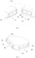
- this embodiment is provided with a display prop splicing device including display bodies 1, luminous bodies 2, and connecting bodies 3, wherein the luminous bodies 2 are erected on and electrically connected with the display bodies 1; the connecting bodies 3 are used for fast electrical connection between the adjacent display bodies 1; a first mounting site 31 and a second mounting site 32 are respectively formed at two ends of each connecting body 3; a third mounting site 11 and a fourth mounting site 12 are respectively formed at two ends of each display body 1; the first mounting sites 31 are cooperated with the third mounting sites 11, and the second mounting sites 32 are cooperated with the fourth mounting sites 12; when two of the display bodies 1 are connected with each other, the third mounting site 11 of one display body 1 is cooperated with the fourth mounting site 12 of the other display body 1; a first magnet 41 and a second magnet 42 which are attracted to each other are arranged in each first mounting site 31 and each third mounting site 11, as well as in each second mounting site 32 and each fourth mounting site 12; conductive poles 51 and 52 used
- a first lug boss 111 is arranged at one end of each display body 1; the first magnets 41 are embedded into the intermediate parts of the first lug bosses 111; and the conductive poles 51 and 52 are embedded into two opposite sides of each first magnet 41; a first recess part is arranged at the other end of each display body 1; the second magnets 42 are embedded into the intermediate parts of the first recess parts; and the conductive poles 51 and 52 are embedded into two opposite sides of each second magnet 42.
- a first connection method is as follows: when two adjacent display bodies 1 are to be connected into a whole, the first lug boss 111 of one display body 1 is inserted into the first recess part 121 of the other display body, and then the two adjacent display bodies are connected into a whole through strong attraction between the corresponding first magnet 41 and the corresponding second magnet 42; and after being connected, the two display bodies 1 are electrically connected through contact between the conductive poles 51 and 52 respectively arranged in the corresponding first lug boss 111 and the corresponding first recess part 121. In this way, the splicing efficiency is high, operation steps of wire soldering, screw hitting and the like are omitted, and the connection is stable and reliable.
- a second connection method of this embodiment is as follows: when required to be spliced into a certain shape along a certain path, a plurality of display bodies 1 can be connected by dint of connecting parts 3 .
- a quadrangular splicing path is used as an example; the connecting bodies 3 are arranged in a fan shape; for the sake of convenient and fast splicing between each connecting body 3 and the display bodies 1 on two sides of the connecting body 3, a second lug boss 321 and a second recess part 311 are respectively arranged at two ends of each connecting body 3; and the first magnets 41 are arranged in the second lug bosses 321, and the second magnets 42 are arranged in the second recess parts 311.
- the first lug bosses 111 are inserted into the second recess parts 311
- the second lug bosses 321 are inserted into the first recess parts 121
- each connecting body 3 and the display bodies 1 on two sides of the connecting body 3 are electrically connected through contact between the conductive poles 51 and 52 arranged in each first lug boss 111 and each second recess parts 311, as well as in each second lug boss 321 and each first recess part 121.
- first lug bosses 111 and the second lug bosses 321 are identical in structure and are enclosed by flanges
- the corresponding first recess parts 121 and the corresponding second recess parts 311 are also identical in structure and are formed in a groove shape
- rabbets cooperated with the flanges are formed in grooves.
- each display body 1 includes a shell 13, a base 14, a positive wire 15, and a negative wire 16, wherein the positive wire 15 and the negative wire 16 are arranged in the length-wise direction of a cavity of the shell 13 and have two ends respectively provided with the conductive poles 51 and 52; the luminous bodies 2 are arranged on the shells 13 and have positive poles electrically connected with the positive wires 15 and negative poles electrically connected with the negative wires 16; and besides, each luminous body 2 includes a display shell 21, a circuit board, LED lamp beads and a diffusion housing 22, wherein the circuit board is arranged in the display shell 21, the LED lamp beads are uniformly distributed on the circuit board, and the diffusion housing 22 covers the display shell 21.
- the display bodies 1 and the luminous bodies 2 can be fixed in a clamping or bonding manner.
- the luminous bodies 2 erected on the display bodies 1 can be displayed in all directions and at different angles through fast splicing of the display bodies 1 along different paths.
- the display shells 21 of the luminous bodies 2 can be formed as letters, Chinese characters, patterns, or the like, so that a better display effect can be fulfilled.
Landscapes
- Engineering & Computer Science (AREA)
- Physics & Mathematics (AREA)
- General Physics & Mathematics (AREA)
- Theoretical Computer Science (AREA)
- General Engineering & Computer Science (AREA)
- Devices For Indicating Variable Information By Combining Individual Elements (AREA)
- Illuminated Signs And Luminous Advertising (AREA)
- Arrangement Of Elements, Cooling, Sealing, Or The Like Of Lighting Devices (AREA)
- Fastening Of Light Sources Or Lamp Holders (AREA)
- Details Of Connecting Devices For Male And Female Coupling (AREA)
Claims (3)
- Ein Displaystützen-Spleißgerät bestehend aus Displayteilen (1), Leuchtkörpern (2) und Verbindungskörpern (3), wobei die Leuchtkörper (2) an den Displayteilen (1) angebracht und mit diesen elektrisch verbunden sind; die Verbindungskörper (3) für eine schnelle elektrische Verbindung zwischen benachbarten Displayteilen (1) verwendet werden; eine erste Befestigungsstelle (31) und eine zweite Befestigungsstelle (32) jeweils an zwei Enden jedes der Verbindungskörper (3) angebracht sind; eine dritte Befestigungsstelle (11) und eine vierte Befestigungsstelle (12) jeweils an zwei Enden jedes der Displayteilen (1) angebracht sind; die ersten Befestigungsstellen (31) mit den dritten Befestigungsstellen (11) und die zweiten Befestigungsstellen (32) mit den vierten Befestigungsstellen (12) verbunden werden; bei zwei miteinander verbundenen Displayteilen (1) die dritte Befestigungsstelle (11) des einen Displayteils (1) mit der vierten Befestigungsstelle (12) des anderen Displayteils (I) verbunden wird; an jeder ersten Befestigungsstelle (31) und jeder dritten Befestigungsstelle (11) sowie an jeder zweiten Befestigungsstelle (32) und jeder vierten Befestigungsstelle (12) ein erster Magnet (41) und ein zweiter Magnet (42) angebracht sind, die sich gegenseitig anziehen; in die Außenkanten jedes ersten Magneten (41) und jedes zweiten Magneten (42) elektrische Pole (51, 52) eingebettet sind, die für die elektrische Verbindung zwischen den benachbarten Displayteilen (1) verwendet werden; und mindestens ein Displayteil (1) über eine Stromleitung (6) elektrisch mit einer externen elektrischen Steuervorrichtung verbunden ist,wobei jedes Displayteil (1) ein Gehäuse (13), einen Sockel (14), ein Plus-Kabel (15) und ein Minus-Kabel (16) umfasst und das Plus-Kabel (15) sowie das Minus-Kabel (16) in Längsrichtung in einem Hohlraum des Gehäuses (13) liegen und zwei Enden aufweisen, die jeweils mit den elektrischen Polen (51, 52) versehen sind,wobei die Leuchtkörper (2) auf den Gehäusen (13) angebracht sind und positive Pole aufweisen, die elektrisch mit den Plus-Kabeln (15) verbunden sind, sowie negative Pole, die elektrisch mit den Minus-Kabeln (16) verbunden sind, und jeder dieser Leuchtkörper (2) ein Displaygehäuse (21), eine Leiterplatte, LED-Leuchtkugeln und ein Diffusionsgehäuse (22) umfasst,wobei die Leiterplatte im Displaygehäuse (21) untergebracht ist, die LED-Leuchtkugeln gleichmäßig auf der Leiterplatte verteilt sind und das Diffusionsgehäuse (22) das Displaygehäuse (21) abdeckt,ein erster Anschlussstutzen (111) an einem Ende jedes der Displayteile (1) angebracht ist; die ersten Magnete (41) in Zwischenteile der ersten Anschlussstutzen (111) eingebettet sind; und die elektrischen Pole (51, 52) in zwei gegenüberliegende Seiten jedes ersten Magneten (41) eingebettet sind,wobei eine erste Aussparung an einem Ende jedes Displayteils (1) angeordnet ist; die zweiten Magnete (42) in Zwischenteile der ersten Aussparungen eingebettet sind; die elektrischen Pole (51, 52) in zwei gegenüberliegende Seiten jedes zweiten Magneten (42) eingebettet sind, und wobei die Verbindungskörper fächerförmig angeordnet sind; ein zweiter Anschlussstutzen (321) und eine zweite Aussparung (311) jeweils an zwei Enden jedes Verbindungskörpers (3) angebracht sind; die ersten Magnete (41) in den zweiten Anschlussstutzen (321) angeordnet sind, und die zweiten Magnete (42) in den zweiten Aussparungen (311) angeordnet sind.
- Das Displaystützen-Spleißgerät nach Patentanspruch 1, wobei die ersten Anschlussstutzen (111) in die zweiten Aussparungen (311) und die zweiten Anschlussstutzen (321) in die ersten Aussparungen (121) eingesetzt sind.
- Das Displaystützen-Spleißgerät nach Patentanspruch 1, wobei die ersten Anschlussstutzen (111) in die ersten Aussparungen (121) eingesetzt sind.
Applications Claiming Priority (1)
| Application Number | Priority Date | Filing Date | Title |
|---|---|---|---|
| CN201910140927.8A CN110197632B (zh) | 2019-02-26 | 2019-02-26 | 一种展示道具拼接装置 |
Publications (3)
| Publication Number | Publication Date |
|---|---|
| EP3703040A1 EP3703040A1 (de) | 2020-09-02 |
| EP3703040C0 EP3703040C0 (de) | 2023-07-05 |
| EP3703040B1 true EP3703040B1 (de) | 2023-07-05 |
Family
ID=66676225
Family Applications (1)
| Application Number | Title | Priority Date | Filing Date |
|---|---|---|---|
| EP19176836.5A Active EP3703040B1 (de) | 2019-02-26 | 2019-05-27 | Anzeigestützenspleissvorrichtung |
Country Status (10)
| Country | Link |
|---|---|
| US (1) | US10832600B2 (de) |
| EP (1) | EP3703040B1 (de) |
| JP (1) | JP7176799B2 (de) |
| KR (1) | KR102478170B1 (de) |
| CN (1) | CN110197632B (de) |
| AU (1) | AU2020229891B2 (de) |
| ES (1) | ES2958084T3 (de) |
| PL (1) | PL3703040T3 (de) |
| RU (1) | RU2768294C1 (de) |
| WO (1) | WO2020173221A1 (de) |
Families Citing this family (7)
| Publication number | Priority date | Publication date | Assignee | Title |
|---|---|---|---|---|
| CN110197632B (zh) * | 2019-02-26 | 2024-05-03 | 深圳市佛光照明有限公司 | 一种展示道具拼接装置 |
| CN111081142A (zh) * | 2020-02-05 | 2020-04-28 | 深圳市佛光照明有限公司 | 一种展示装置 |
| CN111486165A (zh) * | 2020-05-01 | 2020-08-04 | 深圳市佛光照明有限公司 | 一种拼接结构 |
| CN115164058A (zh) * | 2021-04-02 | 2022-10-11 | 深圳市奥拓电子股份有限公司 | 一种led显示屏吊梁 |
| US20230108638A1 (en) * | 2021-10-04 | 2023-04-06 | Bunn-O-Matic Corporation | Magnetic light cord for use with a beverage making and dispensing machine |
| US11480322B1 (en) * | 2021-12-13 | 2022-10-25 | Sikai Chen | Magnetic signage lighting system |
| CN216902174U (zh) * | 2022-01-12 | 2022-07-05 | 广东意高能源科技股份有限公司 | 一种新型的磁吸式发光标识 |
Family Cites Families (44)
| Publication number | Priority date | Publication date | Assignee | Title |
|---|---|---|---|---|
| US1192982A (en) * | 1914-10-12 | 1916-08-01 | Bristol Mfg Company | Sign construction. |
| US1782564A (en) * | 1927-05-21 | 1930-11-25 | Joseph F Coufal | Electric sign |
| US2853819A (en) * | 1955-07-14 | 1958-09-30 | Change Neon Inc U | Electric signs |
| US3363214A (en) * | 1966-01-21 | 1968-01-09 | Charles T. Wright | Magnetic plug adapter |
| US3696548A (en) * | 1971-01-18 | 1972-10-10 | Kinetic Technologies Inc | Educational building toy modules with interior lights and mechanical connections acting as circuit closers |
| JPS54114788U (de) * | 1978-01-31 | 1979-08-11 | ||
| US4532579A (en) * | 1984-04-13 | 1985-07-30 | Bill Merryman | Illuminated interconnectable sign module |
| WO1987006753A1 (en) * | 1986-04-23 | 1987-11-05 | Clarence Tom Foster | Portable illumination display sign |
| SU1764078A1 (ru) * | 1989-09-29 | 1992-09-23 | Соколовско-Сарбайское горно-обогатительное производственное объединение | Информационное табло |
| US5159772A (en) * | 1990-11-26 | 1992-11-03 | Akaley George E | Lighted display signs |
| CN2798237Y (zh) * | 2004-06-08 | 2006-07-19 | 青岛恒星集团有限公司 | 一种徽标展示装置 |
| CN2863560Y (zh) * | 2005-12-06 | 2007-01-31 | 陈隆贤 | 会发光的汽车标志牌 |
| US20080141571A1 (en) * | 2006-10-30 | 2008-06-19 | Hi*Tech Electronic Displays, Inc. | Modular interlocking graphics display panel |
| KR101079920B1 (ko) * | 2010-01-26 | 2011-11-04 | 전숙영 | 엘이디 조립 블럭 및 이를 이용한 표시장치 |
| US7874844B1 (en) * | 2010-02-02 | 2011-01-25 | Fitts Jr Darrell Lynn | Universal magnetic power supply adaptor |
| US8887422B2 (en) * | 2011-08-08 | 2014-11-18 | Ilight Technologies, Inc. | Apparatus pertaining to physically-discrete sign components |
| US20130163234A1 (en) * | 2011-12-21 | 2013-06-27 | Chuang Tzu Hsien | Block led light |
| TWI527990B (zh) * | 2012-10-09 | 2016-04-01 | 廖生興 | 光源節能轉換裝置 |
| JP5514374B1 (ja) | 2013-06-03 | 2014-06-04 | 株式会社ダイカン | 意匠性発光装置および光拡散部材 |
| RU137413U1 (ru) * | 2013-06-10 | 2014-02-10 | Сергей Геннадьевич Поздняков | Модульный магнитный конструктор световых рекламных и информационных вывесок |
| KR200473045Y1 (ko) * | 2014-01-17 | 2014-06-27 | (주)에스피에스 | 이중접점스위치 및 이중접점스위치를 갖는 마그네틱 커넥터 |
| KR200479176Y1 (ko) * | 2014-03-05 | 2015-12-29 | 이성진 | 수수깡 모형용 자석커넥터 |
| FR3018959B1 (fr) * | 2014-03-24 | 2018-07-27 | Lucibel Sa | Interconnecteur structurel et electrique pour un equipement multi-modulaire |
| CN103968284B (zh) * | 2014-04-30 | 2016-01-20 | 深圳市思奥特照明科技有限公司 | 一种滑动式无缝拼接灯具 |
| KR20150130076A (ko) | 2014-05-13 | 2015-11-23 | 가부시키가이샤 엔티솔루션 | 무정전 직관형 led 램프 |
| KR101625063B1 (ko) * | 2014-06-23 | 2016-05-27 | 엘지전자 주식회사 | 조명장치 |
| KR101674593B1 (ko) * | 2014-11-21 | 2016-11-09 | 서동진 | 자석을 이용한 커넥터 |
| CN107110452A (zh) * | 2014-11-24 | 2017-08-29 | 金·舒瓦·夏因 | 模块化照明系统 |
| US20160204544A1 (en) * | 2015-01-08 | 2016-07-14 | Blackrock Microsystems, LLC. | Self-Aligning and Self-Engaging Electrical Connectors |
| US20160245986A1 (en) * | 2015-02-25 | 2016-08-25 | Rambus Delaware Llc | Light guide assembly, housing assembly, and lighting assembly including same |
| CN204494269U (zh) * | 2015-03-31 | 2015-07-22 | 杭州艺繁光纤礼品有限公司 | 一种用于滑动式led字模灯的导轨结构 |
| KR101632535B1 (ko) * | 2015-04-20 | 2016-06-21 | 변승하 | 자석을 포함하는 블록완구 |
| ITUB20151821A1 (it) * | 2015-07-03 | 2017-01-03 | Palestra Massimo Enrico Negri | Dispositivo di illuminazione |
| CN205101899U (zh) * | 2015-11-17 | 2016-03-23 | 东莞市富理特光电科技有限公司 | 一种便携式多功能led灯 |
| CN205461020U (zh) * | 2016-01-13 | 2016-08-17 | 郑浩 | 一种拼接结构组件 |
| CN205488786U (zh) * | 2016-02-03 | 2016-08-17 | 东莞群赞电子开发有限公司 | 一种连接装置 |
| HK1216219A2 (zh) * | 2016-04-27 | 2016-10-21 | Hok Man Lam | 一种拼接式电连接器 |
| CN108062908B (zh) * | 2017-12-29 | 2020-10-23 | 陈忠彪 | 样块展示器 |
| CN107990221B (zh) * | 2017-12-29 | 2020-06-19 | 欧普照明股份有限公司 | 一种组合灯具及照明系统 |
| CN208090372U (zh) * | 2018-01-08 | 2018-11-13 | 东莞新意电子科技有限公司 | 模块化灯具及其发光模块 |
| CN208418245U (zh) * | 2018-05-25 | 2019-01-22 | 杭州康榕进出口有限公司 | 一种新型霓虹灯 |
| CN208352623U (zh) * | 2018-05-29 | 2019-01-08 | 苏州欧普照明有限公司 | 一种连接组件以及台灯 |
| CN209591420U (zh) * | 2019-02-26 | 2019-11-05 | 深圳市佛光照明有限公司 | 一种展示道具拼接装置 |
| CN110197632B (zh) * | 2019-02-26 | 2024-05-03 | 深圳市佛光照明有限公司 | 一种展示道具拼接装置 |
-
2019
- 2019-02-26 CN CN201910140927.8A patent/CN110197632B/zh active Active
- 2019-05-22 US US16/419,182 patent/US10832600B2/en active Active
- 2019-05-27 PL PL19176836.5T patent/PL3703040T3/pl unknown
- 2019-05-27 EP EP19176836.5A patent/EP3703040B1/de active Active
- 2019-05-27 ES ES19176836T patent/ES2958084T3/es active Active
-
2020
- 2020-01-02 AU AU2020229891A patent/AU2020229891B2/en active Active
- 2020-01-02 RU RU2021124898A patent/RU2768294C1/ru active
- 2020-01-02 WO PCT/CN2020/070040 patent/WO2020173221A1/zh not_active Ceased
- 2020-01-02 JP JP2021537129A patent/JP7176799B2/ja active Active
- 2020-01-02 KR KR1020217019444A patent/KR102478170B1/ko active Active
Also Published As
| Publication number | Publication date |
|---|---|
| US10832600B2 (en) | 2020-11-10 |
| CN110197632B (zh) | 2024-05-03 |
| JP2022515618A (ja) | 2022-02-21 |
| AU2020229891A1 (en) | 2021-07-01 |
| CN110197632A (zh) | 2019-09-03 |
| RU2768294C1 (ru) | 2022-03-23 |
| WO2020173221A1 (zh) | 2020-09-03 |
| EP3703040C0 (de) | 2023-07-05 |
| KR102478170B1 (ko) | 2022-12-15 |
| JP7176799B2 (ja) | 2022-11-22 |
| US20200273383A1 (en) | 2020-08-27 |
| PL3703040T3 (pl) | 2023-12-04 |
| EP3703040A1 (de) | 2020-09-02 |
| AU2020229891B2 (en) | 2022-09-29 |
| ES2958084T3 (es) | 2024-02-01 |
| KR20210091810A (ko) | 2021-07-22 |
Similar Documents
| Publication | Publication Date | Title |
|---|---|---|
| EP3703040B1 (de) | Anzeigestützenspleissvorrichtung | |
| EP2937628A1 (de) | Elektrisches verbindungsstück und led-leuchte damit | |
| EP4134554A1 (de) | Modularer, magnetischer lüfter, der bequem zu installieren ist | |
| US11378239B2 (en) | Desk lamp | |
| EP3162420B1 (de) | Modularer block und elektronisches blocksystem | |
| EP3273159A1 (de) | Integrierte elektrische verbindungsstruktur für led-lampe | |
| CN203703874U (zh) | 一种直插小连接器及使用该连接器的led灯 | |
| US11174898B2 (en) | Wiring structure of magnetic suspension bearing, compressor and air conditioner | |
| US10069227B2 (en) | Electrical connector device | |
| US10186793B2 (en) | Light cap electrical connection structure | |
| CN205095419U (zh) | 一种电连接器 | |
| US20200248899A1 (en) | Integrated electrical connector device structure of led light | |
| CN205230819U (zh) | 一种电容的安装结构 | |
| CN107508391A (zh) | 无刷直流电机、定子部件及其绕线方法 | |
| CN203703876U (zh) | 一种简易侧插连接器及使用该连接器的led灯 | |
| CN212113036U (zh) | 一种展示装置 | |
| CN209344437U (zh) | 一种磁吸式展示道具拼接装置 | |
| CN105202495A (zh) | 安装模块、灯具组合 | |
| CN210381430U (zh) | 一种拼接式抗震电路板 | |
| CN111089246A (zh) | 一种led灯快速拆装更换结构 | |
| US20240410565A1 (en) | Easy-to-assembly combined fan | |
| CN212696344U (zh) | 一种usb隔离器 | |
| CN204372837U (zh) | 一种用于led线性灯的灯头及led线性灯 | |
| CN205447673U (zh) | 电连接件 | |
| JP2008035693A (ja) | モータのステーター |
Legal Events
| Date | Code | Title | Description |
|---|---|---|---|
| PUAI | Public reference made under article 153(3) epc to a published international application that has entered the european phase |
Free format text: ORIGINAL CODE: 0009012 |
|
| STAA | Information on the status of an ep patent application or granted ep patent |
Free format text: STATUS: REQUEST FOR EXAMINATION WAS MADE |
|
| 17P | Request for examination filed |
Effective date: 20190527 |
|
| AK | Designated contracting states |
Kind code of ref document: A1 Designated state(s): AL AT BE BG CH CY CZ DE DK EE ES FI FR GB GR HR HU IE IS IT LI LT LU LV MC MK MT NL NO PL PT RO RS SE SI SK SM TR |
|
| AX | Request for extension of the european patent |
Extension state: BA ME |
|
| STAA | Information on the status of an ep patent application or granted ep patent |
Free format text: STATUS: EXAMINATION IS IN PROGRESS |
|
| 17Q | First examination report despatched |
Effective date: 20220126 |
|
| RIC1 | Information provided on ipc code assigned before grant |
Ipc: H01R 13/62 20060101ALI20220810BHEP Ipc: H01R 25/16 20060101ALI20220810BHEP Ipc: G09F 13/04 20060101AFI20220810BHEP |
|
| GRAP | Despatch of communication of intention to grant a patent |
Free format text: ORIGINAL CODE: EPIDOSNIGR1 |
|
| STAA | Information on the status of an ep patent application or granted ep patent |
Free format text: STATUS: GRANT OF PATENT IS INTENDED |
|
| INTG | Intention to grant announced |
Effective date: 20220916 |
|
| GRAS | Grant fee paid |
Free format text: ORIGINAL CODE: EPIDOSNIGR3 |
|
| GRAA | (expected) grant |
Free format text: ORIGINAL CODE: 0009210 |
|
| STAA | Information on the status of an ep patent application or granted ep patent |
Free format text: STATUS: THE PATENT HAS BEEN GRANTED |
|
| AK | Designated contracting states |
Kind code of ref document: B1 Designated state(s): AL AT BE BG CH CY CZ DE DK EE ES FI FR GB GR HR HU IE IS IT LI LT LU LV MC MK MT NL NO PL PT RO RS SE SI SK SM TR |
|
| REG | Reference to a national code |
Ref country code: CH Ref legal event code: EP |
|
| REG | Reference to a national code |
Ref country code: AT Ref legal event code: REF Ref document number: 1585573 Country of ref document: AT Kind code of ref document: T Effective date: 20230715 |
|
| REG | Reference to a national code |
Ref country code: DE Ref legal event code: R096 Ref document number: 602019032003 Country of ref document: DE |
|
| REG | Reference to a national code |
Ref country code: IE Ref legal event code: FG4D |
|
| U01 | Request for unitary effect filed |
Effective date: 20230712 |
|
| U07 | Unitary effect registered |
Designated state(s): AT BE BG DE DK EE FI FR IT LT LU LV MT NL PT SE SI Effective date: 20230724 |
|
| REG | Reference to a national code |
Ref country code: RO Ref legal event code: EPE |
|
| REG | Reference to a national code |
Ref country code: LT Ref legal event code: MG9D |
|
| PG25 | Lapsed in a contracting state [announced via postgrant information from national office to epo] |
Ref country code: GR Free format text: LAPSE BECAUSE OF FAILURE TO SUBMIT A TRANSLATION OF THE DESCRIPTION OR TO PAY THE FEE WITHIN THE PRESCRIBED TIME-LIMIT Effective date: 20231006 |
|
| PG25 | Lapsed in a contracting state [announced via postgrant information from national office to epo] |
Ref country code: IS Free format text: LAPSE BECAUSE OF FAILURE TO SUBMIT A TRANSLATION OF THE DESCRIPTION OR TO PAY THE FEE WITHIN THE PRESCRIBED TIME-LIMIT Effective date: 20231105 |
|
| PG25 | Lapsed in a contracting state [announced via postgrant information from national office to epo] |
Ref country code: RS Free format text: LAPSE BECAUSE OF FAILURE TO SUBMIT A TRANSLATION OF THE DESCRIPTION OR TO PAY THE FEE WITHIN THE PRESCRIBED TIME-LIMIT Effective date: 20230705 Ref country code: NO Free format text: LAPSE BECAUSE OF FAILURE TO SUBMIT A TRANSLATION OF THE DESCRIPTION OR TO PAY THE FEE WITHIN THE PRESCRIBED TIME-LIMIT Effective date: 20231005 Ref country code: IS Free format text: LAPSE BECAUSE OF FAILURE TO SUBMIT A TRANSLATION OF THE DESCRIPTION OR TO PAY THE FEE WITHIN THE PRESCRIBED TIME-LIMIT Effective date: 20231105 Ref country code: HR Free format text: LAPSE BECAUSE OF FAILURE TO SUBMIT A TRANSLATION OF THE DESCRIPTION OR TO PAY THE FEE WITHIN THE PRESCRIBED TIME-LIMIT Effective date: 20230705 Ref country code: GR Free format text: LAPSE BECAUSE OF FAILURE TO SUBMIT A TRANSLATION OF THE DESCRIPTION OR TO PAY THE FEE WITHIN THE PRESCRIBED TIME-LIMIT Effective date: 20231006 |
|
| REG | Reference to a national code |
Ref country code: ES Ref legal event code: FG2A Ref document number: 2958084 Country of ref document: ES Kind code of ref document: T3 Effective date: 20240201 |
|
| PG25 | Lapsed in a contracting state [announced via postgrant information from national office to epo] |
Ref country code: PL Free format text: LAPSE BECAUSE OF FAILURE TO SUBMIT A TRANSLATION OF THE DESCRIPTION OR TO PAY THE FEE WITHIN THE PRESCRIBED TIME-LIMIT Effective date: 20230705 |
|
| REG | Reference to a national code |
Ref country code: DE Ref legal event code: R097 Ref document number: 602019032003 Country of ref document: DE |
|
| PG25 | Lapsed in a contracting state [announced via postgrant information from national office to epo] |
Ref country code: SM Free format text: LAPSE BECAUSE OF FAILURE TO SUBMIT A TRANSLATION OF THE DESCRIPTION OR TO PAY THE FEE WITHIN THE PRESCRIBED TIME-LIMIT Effective date: 20230705 Ref country code: SK Free format text: LAPSE BECAUSE OF FAILURE TO SUBMIT A TRANSLATION OF THE DESCRIPTION OR TO PAY THE FEE WITHIN THE PRESCRIBED TIME-LIMIT Effective date: 20230705 |
|
| PLBE | No opposition filed within time limit |
Free format text: ORIGINAL CODE: 0009261 |
|
| STAA | Information on the status of an ep patent application or granted ep patent |
Free format text: STATUS: NO OPPOSITION FILED WITHIN TIME LIMIT |
|
| 26N | No opposition filed |
Effective date: 20240408 |
|
| U20 | Renewal fee for the european patent with unitary effect paid |
Year of fee payment: 6 Effective date: 20240527 |
|
| PG2D | Information on lapse in contracting state deleted |
Ref country code: PL |
|
| PG25 | Lapsed in a contracting state [announced via postgrant information from national office to epo] |
Ref country code: MC Free format text: LAPSE BECAUSE OF FAILURE TO SUBMIT A TRANSLATION OF THE DESCRIPTION OR TO PAY THE FEE WITHIN THE PRESCRIBED TIME-LIMIT Effective date: 20230705 |
|
| PG25 | Lapsed in a contracting state [announced via postgrant information from national office to epo] |
Ref country code: MC Free format text: LAPSE BECAUSE OF FAILURE TO SUBMIT A TRANSLATION OF THE DESCRIPTION OR TO PAY THE FEE WITHIN THE PRESCRIBED TIME-LIMIT Effective date: 20230705 |
|
| PG25 | Lapsed in a contracting state [announced via postgrant information from national office to epo] |
Ref country code: IE Free format text: LAPSE BECAUSE OF NON-PAYMENT OF DUE FEES Effective date: 20240527 |
|
| U20 | Renewal fee for the european patent with unitary effect paid |
Year of fee payment: 7 Effective date: 20250522 |
|
| PGFP | Annual fee paid to national office [announced via postgrant information from national office to epo] |
Ref country code: PL Payment date: 20250524 Year of fee payment: 7 |
|
| PGFP | Annual fee paid to national office [announced via postgrant information from national office to epo] |
Ref country code: GB Payment date: 20250526 Year of fee payment: 7 Ref country code: ES Payment date: 20250611 Year of fee payment: 7 |
|
| PGFP | Annual fee paid to national office [announced via postgrant information from national office to epo] |
Ref country code: CH Payment date: 20250601 Year of fee payment: 7 |
|
| PGFP | Annual fee paid to national office [announced via postgrant information from national office to epo] |
Ref country code: RO Payment date: 20250526 Year of fee payment: 7 |
|
| PGFP | Annual fee paid to national office [announced via postgrant information from national office to epo] |
Ref country code: TR Payment date: 20250527 Year of fee payment: 7 |
|
| PGFP | Annual fee paid to national office [announced via postgrant information from national office to epo] |
Ref country code: CZ Payment date: 20250523 Year of fee payment: 7 |
|
| PG25 | Lapsed in a contracting state [announced via postgrant information from national office to epo] |
Ref country code: HU Free format text: LAPSE BECAUSE OF FAILURE TO SUBMIT A TRANSLATION OF THE DESCRIPTION OR TO PAY THE FEE WITHIN THE PRESCRIBED TIME-LIMIT; INVALID AB INITIO Effective date: 20190527 |
|
| PG25 | Lapsed in a contracting state [announced via postgrant information from national office to epo] |
Ref country code: CY Free format text: LAPSE BECAUSE OF FAILURE TO SUBMIT A TRANSLATION OF THE DESCRIPTION OR TO PAY THE FEE WITHIN THE PRESCRIBED TIME-LIMIT; INVALID AB INITIO Effective date: 20190527 |