EP3702802A1 - Procédé de fusion de données multicapteurs - Google Patents
Procédé de fusion de données multicapteurs Download PDFInfo
- Publication number
- EP3702802A1 EP3702802A1 EP19160260.6A EP19160260A EP3702802A1 EP 3702802 A1 EP3702802 A1 EP 3702802A1 EP 19160260 A EP19160260 A EP 19160260A EP 3702802 A1 EP3702802 A1 EP 3702802A1
- Authority
- EP
- European Patent Office
- Prior art keywords
- data sets
- coordinate system
- sensor
- neural network
- data
- Prior art date
- Legal status (The legal status is an assumption and is not a legal conclusion. Google has not performed a legal analysis and makes no representation as to the accuracy of the status listed.)
- Pending
Links
- 238000000034 method Methods 0.000 title claims abstract description 37
- 230000004927 fusion Effects 0.000 title claims abstract description 28
- 230000009466 transformation Effects 0.000 claims abstract description 44
- 230000001131 transforming effect Effects 0.000 claims abstract description 9
- 238000013528 artificial neural network Methods 0.000 claims description 60
- 238000013507 mapping Methods 0.000 claims description 28
- 238000013527 convolutional neural network Methods 0.000 claims description 19
- 238000012545 processing Methods 0.000 claims description 14
- 238000000844 transformation Methods 0.000 claims description 7
- 238000012549 training Methods 0.000 claims description 5
- 230000008447 perception Effects 0.000 description 9
- 230000006870 function Effects 0.000 description 4
- 238000013459 approach Methods 0.000 description 3
- 238000001514 detection method Methods 0.000 description 3
- 239000011159 matrix material Substances 0.000 description 3
- 230000011218 segmentation Effects 0.000 description 3
- 238000005516 engineering process Methods 0.000 description 2
- 238000000605 extraction Methods 0.000 description 2
- 238000010801 machine learning Methods 0.000 description 2
- 239000013598 vector Substances 0.000 description 2
- 230000009286 beneficial effect Effects 0.000 description 1
- 230000001419 dependent effect Effects 0.000 description 1
- 238000011161 development Methods 0.000 description 1
- 230000018109 developmental process Effects 0.000 description 1
- 238000004519 manufacturing process Methods 0.000 description 1
- 238000012800 visualization Methods 0.000 description 1
Images


Classifications
-
- G—PHYSICS
- G06—COMPUTING; CALCULATING OR COUNTING
- G06F—ELECTRIC DIGITAL DATA PROCESSING
- G06F18/00—Pattern recognition
- G06F18/20—Analysing
- G06F18/25—Fusion techniques
-
- G—PHYSICS
- G01—MEASURING; TESTING
- G01S—RADIO DIRECTION-FINDING; RADIO NAVIGATION; DETERMINING DISTANCE OR VELOCITY BY USE OF RADIO WAVES; LOCATING OR PRESENCE-DETECTING BY USE OF THE REFLECTION OR RERADIATION OF RADIO WAVES; ANALOGOUS ARRANGEMENTS USING OTHER WAVES
- G01S13/00—Systems using the reflection or reradiation of radio waves, e.g. radar systems; Analogous systems using reflection or reradiation of waves whose nature or wavelength is irrelevant or unspecified
- G01S13/88—Radar or analogous systems specially adapted for specific applications
- G01S13/93—Radar or analogous systems specially adapted for specific applications for anti-collision purposes
- G01S13/931—Radar or analogous systems specially adapted for specific applications for anti-collision purposes of land vehicles
-
- G—PHYSICS
- G01—MEASURING; TESTING
- G01S—RADIO DIRECTION-FINDING; RADIO NAVIGATION; DETERMINING DISTANCE OR VELOCITY BY USE OF RADIO WAVES; LOCATING OR PRESENCE-DETECTING BY USE OF THE REFLECTION OR RERADIATION OF RADIO WAVES; ANALOGOUS ARRANGEMENTS USING OTHER WAVES
- G01S13/00—Systems using the reflection or reradiation of radio waves, e.g. radar systems; Analogous systems using reflection or reradiation of waves whose nature or wavelength is irrelevant or unspecified
- G01S13/86—Combinations of radar systems with non-radar systems, e.g. sonar, direction finder
- G01S13/865—Combination of radar systems with lidar systems
-
- G—PHYSICS
- G01—MEASURING; TESTING
- G01S—RADIO DIRECTION-FINDING; RADIO NAVIGATION; DETERMINING DISTANCE OR VELOCITY BY USE OF RADIO WAVES; LOCATING OR PRESENCE-DETECTING BY USE OF THE REFLECTION OR RERADIATION OF RADIO WAVES; ANALOGOUS ARRANGEMENTS USING OTHER WAVES
- G01S13/00—Systems using the reflection or reradiation of radio waves, e.g. radar systems; Analogous systems using reflection or reradiation of waves whose nature or wavelength is irrelevant or unspecified
- G01S13/86—Combinations of radar systems with non-radar systems, e.g. sonar, direction finder
- G01S13/867—Combination of radar systems with cameras
-
- G—PHYSICS
- G01—MEASURING; TESTING
- G01S—RADIO DIRECTION-FINDING; RADIO NAVIGATION; DETERMINING DISTANCE OR VELOCITY BY USE OF RADIO WAVES; LOCATING OR PRESENCE-DETECTING BY USE OF THE REFLECTION OR RERADIATION OF RADIO WAVES; ANALOGOUS ARRANGEMENTS USING OTHER WAVES
- G01S17/00—Systems using the reflection or reradiation of electromagnetic waves other than radio waves, e.g. lidar systems
- G01S17/86—Combinations of lidar systems with systems other than lidar, radar or sonar, e.g. with direction finders
-
- G—PHYSICS
- G01—MEASURING; TESTING
- G01S—RADIO DIRECTION-FINDING; RADIO NAVIGATION; DETERMINING DISTANCE OR VELOCITY BY USE OF RADIO WAVES; LOCATING OR PRESENCE-DETECTING BY USE OF THE REFLECTION OR RERADIATION OF RADIO WAVES; ANALOGOUS ARRANGEMENTS USING OTHER WAVES
- G01S17/00—Systems using the reflection or reradiation of electromagnetic waves other than radio waves, e.g. lidar systems
- G01S17/88—Lidar systems specially adapted for specific applications
- G01S17/93—Lidar systems specially adapted for specific applications for anti-collision purposes
- G01S17/931—Lidar systems specially adapted for specific applications for anti-collision purposes of land vehicles
-
- G—PHYSICS
- G01—MEASURING; TESTING
- G01S—RADIO DIRECTION-FINDING; RADIO NAVIGATION; DETERMINING DISTANCE OR VELOCITY BY USE OF RADIO WAVES; LOCATING OR PRESENCE-DETECTING BY USE OF THE REFLECTION OR RERADIATION OF RADIO WAVES; ANALOGOUS ARRANGEMENTS USING OTHER WAVES
- G01S7/00—Details of systems according to groups G01S13/00, G01S15/00, G01S17/00
- G01S7/02—Details of systems according to groups G01S13/00, G01S15/00, G01S17/00 of systems according to group G01S13/00
- G01S7/28—Details of pulse systems
- G01S7/285—Receivers
- G01S7/295—Means for transforming co-ordinates or for evaluating data, e.g. using computers
-
- G—PHYSICS
- G06—COMPUTING; CALCULATING OR COUNTING
- G06F—ELECTRIC DIGITAL DATA PROCESSING
- G06F18/00—Pattern recognition
- G06F18/20—Analysing
- G06F18/21—Design or setup of recognition systems or techniques; Extraction of features in feature space; Blind source separation
- G06F18/214—Generating training patterns; Bootstrap methods, e.g. bagging or boosting
-
- G—PHYSICS
- G06—COMPUTING; CALCULATING OR COUNTING
- G06F—ELECTRIC DIGITAL DATA PROCESSING
- G06F18/00—Pattern recognition
- G06F18/20—Analysing
- G06F18/25—Fusion techniques
- G06F18/253—Fusion techniques of extracted features
-
- G—PHYSICS
- G06—COMPUTING; CALCULATING OR COUNTING
- G06F—ELECTRIC DIGITAL DATA PROCESSING
- G06F18/00—Pattern recognition
- G06F18/20—Analysing
- G06F18/25—Fusion techniques
- G06F18/254—Fusion techniques of classification results, e.g. of results related to same input data
-
- G—PHYSICS
- G06—COMPUTING; CALCULATING OR COUNTING
- G06N—COMPUTING ARRANGEMENTS BASED ON SPECIFIC COMPUTATIONAL MODELS
- G06N3/00—Computing arrangements based on biological models
- G06N3/02—Neural networks
- G06N3/04—Architecture, e.g. interconnection topology
- G06N3/043—Architecture, e.g. interconnection topology based on fuzzy logic, fuzzy membership or fuzzy inference, e.g. adaptive neuro-fuzzy inference systems [ANFIS]
-
- G—PHYSICS
- G06—COMPUTING; CALCULATING OR COUNTING
- G06N—COMPUTING ARRANGEMENTS BASED ON SPECIFIC COMPUTATIONAL MODELS
- G06N3/00—Computing arrangements based on biological models
- G06N3/02—Neural networks
- G06N3/04—Architecture, e.g. interconnection topology
- G06N3/045—Combinations of networks
-
- G—PHYSICS
- G06—COMPUTING; CALCULATING OR COUNTING
- G06N—COMPUTING ARRANGEMENTS BASED ON SPECIFIC COMPUTATIONAL MODELS
- G06N3/00—Computing arrangements based on biological models
- G06N3/02—Neural networks
- G06N3/08—Learning methods
-
- G—PHYSICS
- G06—COMPUTING; CALCULATING OR COUNTING
- G06V—IMAGE OR VIDEO RECOGNITION OR UNDERSTANDING
- G06V10/00—Arrangements for image or video recognition or understanding
- G06V10/70—Arrangements for image or video recognition or understanding using pattern recognition or machine learning
- G06V10/764—Arrangements for image or video recognition or understanding using pattern recognition or machine learning using classification, e.g. of video objects
-
- G—PHYSICS
- G06—COMPUTING; CALCULATING OR COUNTING
- G06V—IMAGE OR VIDEO RECOGNITION OR UNDERSTANDING
- G06V10/00—Arrangements for image or video recognition or understanding
- G06V10/70—Arrangements for image or video recognition or understanding using pattern recognition or machine learning
- G06V10/77—Processing image or video features in feature spaces; using data integration or data reduction, e.g. principal component analysis [PCA] or independent component analysis [ICA] or self-organising maps [SOM]; Blind source separation
- G06V10/80—Fusion, i.e. combining data from various sources at the sensor level, preprocessing level, feature extraction level or classification level
- G06V10/806—Fusion, i.e. combining data from various sources at the sensor level, preprocessing level, feature extraction level or classification level of extracted features
-
- G—PHYSICS
- G06—COMPUTING; CALCULATING OR COUNTING
- G06V—IMAGE OR VIDEO RECOGNITION OR UNDERSTANDING
- G06V10/00—Arrangements for image or video recognition or understanding
- G06V10/70—Arrangements for image or video recognition or understanding using pattern recognition or machine learning
- G06V10/77—Processing image or video features in feature spaces; using data integration or data reduction, e.g. principal component analysis [PCA] or independent component analysis [ICA] or self-organising maps [SOM]; Blind source separation
- G06V10/80—Fusion, i.e. combining data from various sources at the sensor level, preprocessing level, feature extraction level or classification level
- G06V10/809—Fusion, i.e. combining data from various sources at the sensor level, preprocessing level, feature extraction level or classification level of classification results, e.g. where the classifiers operate on the same input data
-
- G—PHYSICS
- G06—COMPUTING; CALCULATING OR COUNTING
- G06V—IMAGE OR VIDEO RECOGNITION OR UNDERSTANDING
- G06V10/00—Arrangements for image or video recognition or understanding
- G06V10/70—Arrangements for image or video recognition or understanding using pattern recognition or machine learning
- G06V10/82—Arrangements for image or video recognition or understanding using pattern recognition or machine learning using neural networks
-
- G—PHYSICS
- G06—COMPUTING; CALCULATING OR COUNTING
- G06V—IMAGE OR VIDEO RECOGNITION OR UNDERSTANDING
- G06V20/00—Scenes; Scene-specific elements
- G06V20/50—Context or environment of the image
- G06V20/56—Context or environment of the image exterior to a vehicle by using sensors mounted on the vehicle
- G06V20/58—Recognition of moving objects or obstacles, e.g. vehicles or pedestrians; Recognition of traffic objects, e.g. traffic signs, traffic lights or roads
-
- H—ELECTRICITY
- H04—ELECTRIC COMMUNICATION TECHNIQUE
- H04L—TRANSMISSION OF DIGITAL INFORMATION, e.g. TELEGRAPHIC COMMUNICATION
- H04L1/00—Arrangements for detecting or preventing errors in the information received
- H04L1/004—Arrangements for detecting or preventing errors in the information received by using forward error control
- H04L1/0056—Systems characterized by the type of code used
- H04L1/0057—Block codes
-
- H—ELECTRICITY
- H04—ELECTRIC COMMUNICATION TECHNIQUE
- H04L—TRANSMISSION OF DIGITAL INFORMATION, e.g. TELEGRAPHIC COMMUNICATION
- H04L7/00—Arrangements for synchronising receiver with transmitter
- H04L7/0016—Arrangements for synchronising receiver with transmitter correction of synchronization errors
- H04L7/002—Arrangements for synchronising receiver with transmitter correction of synchronization errors correction by interpolation
- H04L7/0029—Arrangements for synchronising receiver with transmitter correction of synchronization errors correction by interpolation interpolation of received data signal
-
- B—PERFORMING OPERATIONS; TRANSPORTING
- B60—VEHICLES IN GENERAL
- B60W—CONJOINT CONTROL OF VEHICLE SUB-UNITS OF DIFFERENT TYPE OR DIFFERENT FUNCTION; CONTROL SYSTEMS SPECIALLY ADAPTED FOR HYBRID VEHICLES; ROAD VEHICLE DRIVE CONTROL SYSTEMS FOR PURPOSES NOT RELATED TO THE CONTROL OF A PARTICULAR SUB-UNIT
- B60W50/00—Details of control systems for road vehicle drive control not related to the control of a particular sub-unit, e.g. process diagnostic or vehicle driver interfaces
- B60W2050/0001—Details of the control system
- B60W2050/0043—Signal treatments, identification of variables or parameters, parameter estimation or state estimation
- B60W2050/006—Interpolation; Extrapolation
-
- B—PERFORMING OPERATIONS; TRANSPORTING
- B60—VEHICLES IN GENERAL
- B60W—CONJOINT CONTROL OF VEHICLE SUB-UNITS OF DIFFERENT TYPE OR DIFFERENT FUNCTION; CONTROL SYSTEMS SPECIALLY ADAPTED FOR HYBRID VEHICLES; ROAD VEHICLE DRIVE CONTROL SYSTEMS FOR PURPOSES NOT RELATED TO THE CONTROL OF A PARTICULAR SUB-UNIT
- B60W50/00—Details of control systems for road vehicle drive control not related to the control of a particular sub-unit, e.g. process diagnostic or vehicle driver interfaces
Definitions
- a method for multi-sensor data fusion comprises that data is gathered from various sensors and then merged together.
- different types of sensors can be used for acquiring sensor-specific views on an environment, wherein the sensor-specific views are fused into one single unified view.
- the sensor-specific views can be partially redundant and the aim of fusing can be to extract one unified view, which is more powerful than the individual views.
- the unified view can be more reliable or can carry more information than each of the single views.
- the sensor-specific views may be represented in a sensor-specific format, which can deviate from the desired target format for the unified view.
- modern automotive perception systems require multiple sensors which vary with respect to their type, e.g., there can be an image sensor for taking images or videos (e.g., a camera), another sensor formed by a radar system for taking "three-dimensional images" (sometimes denoted as point clouds comprising, e.g., depth and/or velocity information) by means of radar waves, and yet another sensor formed by a LiDAR-(light detection and ranging) system for providing further images by using laser rays.
- These sensors or other sensors are mounted on a vehicle at different mounting positions (e.g., front, rear or side). The images are thus captured from different viewpoints, i.e. from different perspectives.
- multi-sensor data fusion all the information captured by the different sensors should be merged in order to infer a precise and robust perception result.
- Various fusing algorithms are known from the art.
- CNNs deep convolutional neural networks
- the input to a neural network can be for example a multidimensional tensor, e.g., a 2-D image with multiple channels or 3-D voxels, which is defined in a spatial coordinate system.
- a neural network does not change the spatial representation; the output is thus defined in the same coordinate system as the input.
- each sensor output is usually processed separately by means of neural networks. This is because the sensor outputs may have different definitions and processing them together by means of one single neural network can reduce the accuracy. Therefore, fusing of the sensor outputs may involve a step of finding correspondences between objects or other information pieces between the processed sensor outputs (e.g., identifying the same object in two different feature maps). Despite some success it has been found that the robustness has still not reached a satisfactory level.
- a method for multi-sensor data fusion comprises the following steps:
- transformation rule which forms a link between the sensor coordinate systems and unified coordinate system. It is noted that the transformation rule may be regarded as a means for compensating or equalising the differences between the individual sensor coordinate systems with respect to the unified coordinate system. It has been found that this approach improves the overall accuracy of the multi-sensor data fusion.
- each of the sensors can have its own sensor coordinate system, i.e., each of the sensors is associated with a respective one of the sensor coordinate systems.
- a camera may be associated with a projection coordinate system
- RADAR and/or LiDAR sensors may be associated with a Cartesian or Polar coordinate system.
- each sensor coordinate system can depend on the type of sensor.
- each sensor coordinate system can depend on the mounting position of the corresponding sensor.
- each sensor can have its local coordinate system depending on its mounting position.
- each of the sensors can be configured to capture an environment around the sensor.
- the unified coordinate system can also be denoted as target coordinate system in which the target information, i.e., the fused data sets should be provided.
- the unified coordinate system can be, e.g., a Cartesian coordinate system. While in some applications only a single unified coordinate system may be used, a plurality of unified coordinate systems may be be adopted for specific perception tasks.
- the method may be incorporated into an automotive perception system, wherein the plurality of sensors are mounted on a vehicle.
- the outputs of the sensors, i.e. the first data sets may then be processed by means of neural networks, wherein the individual datasets are transformed from their respective sensor coordinate system to the unified coordinate system.
- this transformation is applied before fusing of the transformed datasets, i.e. the second data sets.
- each of the first and second data sets is preferably associated with the sensor, which is used for determining the respective data set. Therefore, when applying the transformation rule, it is known for each of the first datasets, which of the sensor coordinate systems is applicable.
- each of the first data sets and or each of the second data sets may comprise one or more data values.
- These data values can have any form and can be formed, for example by scalar values, which are associated with one or more coordinates that indicate the location in the corresponding coordinate system of the sensor.
- the data values may be formed by pixel values being associated with a respective position (e.g., coordinate values on an x-axis and a y-axis).
- the data values may be formed by points being associated with a respective position in the field of view of the radar sensor (the points may carry distance and/or depth information).
- the respective position can be defined in polar coordinates, i.e. by means of an angle and a radius.
- the first and/or second data sets may also be denoted as data maps or feature maps, wherein each of the maps may comprise a plurality of points (i.e. data values), which together may also be interpreted as a point cloud.
- the transformation rule comprises a plurality of predetermined coordinate transformations for transforming data values from a respective one of the sensor coordinate systems to the unified coordinate system and vice versa, wherein the plurality of predetermined coordinate transformations are based on fixed relationships between the mounting positions and the at least one reference point.
- the transformation rule and/or the coordinate transformations can be stored in a storage device.
- the mounting positions and the at least one reference point are preferably defined in dependence of a vehicle, in particular wherein the reference point is located on a predetermined part (e.g., a front bumper or a rear axis) of the vehicle and the mounting positions are located in various predetermined parts of the vehicle that might be different from the part of the reference point.
- the fixed relationships can depend on the vehicle and can thus be encoded in the transformation rule in a predetermined manner. It is assumed that the relationships do not change over time. However, it can be provided that the fixed relationships are updated regularly or upon a relevant change. This can be the case, for example, when small deviations between a desired mounting position and a true mounting position become relevant, e.g. due to manufacturing tolerances or operational influences.
- the transformation rule can comprise one or more transformation matrices, which are stored in a storage device, for example, in a vehicle. Each of the coordinate transformations can be associated with a transformation matrix that defines the coordinate transformation.
- the transformation rule comprises a mapping rule, which includes at least one definition of a plurality of first positions for the respective one of the sensor coordinate systems and a definition of a plurality of second positions for the unified coordinate system.
- the mapping rule also comprises a mapping of each of the second positions to at least some of the first positions.
- Each of the sensor coordinate systems can be associated with a respective definition of first positions and mappings.
- the definition of second positions is preferably constant.
- transforming a respective one of the first data sets can comprise determining, for each of the second positions, a target value for the respective second data set on the basis of source values of the respective first data set, the source values being located at the first positions that are mapped to the respective second position according to the mapping rule. Therefore, according to the mapping each of the second positions is associated with at least one or preferably a subset of the first positions. This can be regarded as defining a spatial correspondence between the underlying coordinate systems.
- mapping is defined in a direction from the unified coordinate system to a respective sensor coordinate system, which has practical advantages.
- the mapping rule could in principle also be defined in the opposite direction.
- the source values can be formed by data values in a respective one of the first data sets, wherein these data values are derived or defined by the first positions according to the mapping. If there are no data values at the first positions that are mapped to the respective second position then it can be provided that the nearest data values are selected as source values. For this purpose, one or more rounding operations can be incorporated into the mapping rule for selecting the source values from the respective first data set.
- first positions correspond to cells of a first regular grid, the first regular grid being adapted to the respective one of the sensor coordinate systems.
- the second positions can correspond to cells of a second regular grid, the second regular grid being adapted to the unified coordinate system.
- grids allows for reducing the amount of involved data, wherein the principal complexity in the data sets is reduced to a limited number of cells or points.
- a respective cell can be formed by a predetermined area, which is defined by the grid.
- the transformation rule can further comprise an interpolation rule, the interpolation rule being differentiable, and wherein determining of the target value comprises an interpolation from the source values, in particular wherein the interpolation is a bilinear interpolation.
- the interpolation rule which can be formed by an interpolation function, is differentiate. Therefore, an efficient and well-defined training of the neural network can be ensured in combination with the transformation rule.
- At least one of the first data sets is associated with a sensor coordinate system being a Polar coordinate system, and wherein the unified coordinate system is a Cartesian coordinate system.
- the unified coordinate system can be a global coordinate system that is associated with a predefined object, in particular a vehicle. If the unified coordinate system is associated with a vehicle the coordinate system can also be denoted as vehicle coordinate system.
- determining of the first data sets comprises a step of acquiring a plurality of raw data sets by means of the plurality of sensors.
- the first data sets can be extracted on the basis of the raw data sets, wherein the first data sets are extracted from the raw data sets by means of one or more neural networks or portions of a global neural network, in particular wherein the one or more neural networks or the global neural network are convolutional neural networks. It has been found that in some cases it is beneficial to do not apply the transformation rule to the raw data sets although this is possible in principle (in which case the raw data sets can be regarded as first data sets). Instead, it is preferred to extract the first data sets from the raw datasets by means of neural network technology.
- the resulting first data sets can also be regarded as feature maps, which is a common term in the field of neural networks. Although the raw data is processed by means of a neural network the resulting first data set can still represent comparably low-level features. Therefore, transformation to the unified coordinate system can still appear in an early stage of the overall processing chain. It is understood that the second data sets can also be denoted as second feature maps.
- the second data sets can be processed by means of one or more neural networks or portions of a global neural network, wherein the one or more neural networks or the global neural network are preferably formed by one or more convolutional neural networks.
- the fused data set can be processed further to extract semantic information, for example information on object boundaries or general segmentation data.
- the fused data set may be used as desired within the framework of an application. For example, if the data of multiple sensors mounted on a vehicle are processed then the fused data set can be used for automated control of a vehicle. In this way, automated driving applications, in particular autonomous driving can be made available.
- fusing can comprise that at least some of the second data sets are stacked together and then processed further by means of a neural network, in particular a convolutional neural network.
- a neural network in particular a convolutional neural network.
- all of the second data sets are stacked together.
- the second data sets can be concatenated perpendicular to the dimensions of the data sets.
- the stacked data sets can form a tensor.
- a feature or data selective approach can be performed. This can be done when the second data sets are associated with a plurality of feature types, i.e. for a given sensor various first or second data sets are provided, wherein each of the first data sets corresponds to a feature type. Fusing can then comprise that groups (i.e. subsets) of second data sets are determined by stacking at least some, preferably all of the second data sets or portions thereof per feature type, wherein each of the groups of second data sets is processed by means of one or more neural networks or portions of a global neural network.
- the one or more neural networks or the global neural network are preferably convolutional neural networks.
- the method or portions thereof are preferably performed by means of a neural network, in particular convolutional neural network.
- a plurality of neural networks can be employed and combined with the transformation rule.
- the transformation step can be performed in a dedicated transformation module incorporated into a neural network or combined with several neural networks.
- the neural networks can be distinct from each other. In this case, the networks can be numbered. However, it can be provided that some of the networks, for example the global networks are formed by one single network.
- the disclosure further relates to a method for training a neural network for multi-sensor data fusion by using a gradient-based training method, comprising the following steps: - processing a gradient by means of a plurality neural networks or portions of a neural network - transforming the gradient between two adjacent ones of the neural networks or portions of the neural network by means of a predetermined transformation rule.
- the transformation can be the same as set forth further above.
- a device for multi-sensor data fusion comprising: an input for receiving data sets from a plurality of sensors and an output for providing a fused data set or an information determined on the basis of the fused data set, wherein the device is configured to perform the method according to one of the preceding embodiments.
- the device can be formed by a processing device having a processor and a storage unit in which the instructions of the method are stored. When being executed these instructions cause the processor to perform the method.
- a vehicle which is configured to perform multi-sensor fusion.
- the vehicle comprises a plurality of sensors mounted on the vehicle at various mounting positions and a control unit being connected to the sensors, wherein the control unit is configured to control the vehicle in dependence of at least one fused data set that is determined by means of the device.
- a method for multi-sensor data fusion is illustrated, wherein two sensors 10a and 10b are mounted at predetermined mounting positions on a device (not shown).
- the sensors 10a, 10b are also denoted as S and S' in Fig. 1 . It is understood that also more than two sensors can be used.
- the sensor 10a can be, e.g., a camera for taking two-dimensional images.
- the other sensor 10b can be a radar sensor for taking radar images comprising velocity information. These radar images are sometimes denoted as point clouds.
- each of the raw data sets 14a, 14b can comprise a plurality of data points, each of the points being associated with a spatial position (see, e.g. maps 15 in Fig. 2 ).
- the data points can be formed by pixel values (for example when the sensor is an image sensor) or detection points acquired by means of radar (radar sensor) or other electromagnetic waves, for example laser (Lidar).
- First feature maps 18a and 18b are extracted from the raw datasets 14a and 14b in steps 16a and 16b, respectively.
- the first feature maps 18a, 18b can be extracted by using a predefined computer-implemented model that is trained before the desired use by way of machine learning, i.e. the model used for extraction can be formed, e.g., by a neural network or the like.
- the models used in steps 16a, 16b can be the same or different.
- the first feature maps 18a, 18b represent data sets and can generally comprise a plurality of data points.
- the structure of the first feature maps 18a, 18b can be the same or similar to the structure of the raw data sets 14a, 14b.
- the feature maps 18a, 18b also comprise one or more representations of features in a dedicated sensor coordinate system.
- the feature maps 18a represent feature data (e.g., data points with some meaning or reliability) in a sensor coordinate system of the sensor 10a.
- the feature map 18b represents feature data in a sensor coordinate system of the sensor 10b.
- the feature maps 18a and 18b are transformed into a unified coordinate system, i.e. the data of the feature maps 18a and 18b is represented in the same coordinate system after the transformation.
- the unified coordinate system is preferably defined independently from the sensor coordinate systems of sensors 10a, 10b. Instead, the unified coordinate system is defined in dependence of a predetermined reference point at an object, for example a predetermined position on a vehicle.
- the transformed feature maps 20a and 20b are denoted as second feature maps.
- the second feature maps 20a, 20b are then fused together in step 24. This results in at least one fused data set 35.
- FIG. 2 a further embodiment of a method for sensor data fusion is illustrated.
- a plurality of maps 15 are acquired by means of four sensors 10a, 10b, 10c, 10d, which are all mounted at the outer corners of a vehicle V.
- This arrangement is merely an example and any suitable mounting position can be selected for mounting, i.e. installing the sensors on the vehicle V.
- the maps 15 corresponds to raw data sets 14a, 14b, 14c, and 14d, wherein the maps 15 can be interpreted as visualisations of the raw data sets 14a, 14b, 14c, and 14d.
- Each of the data sets 14a, 14b, 14c, 14d is then processed by a respective one of convolutional neural networks 26.
- This step can be interpreted as a feature extraction (cf. steps 16a, 16b in Fig. 1 ), which results in a plurality of first feature maps 18a, 18b, 18c and 18d, wherein feature map 18a corresponds to the processed version of the raw dataset 14a, feature map 18b corresponds to the processed version of the raw data set 14b, and so forth.
- a plurality of mappings 28 is then applied to the first feature maps 18a, 18b, 18c, and 18d.
- each of the mappings 28 corresponds to a step where a dedicated mapping rule is applied to the underlying one of the first feature maps 18a, 18b, 18c, 18d.
- each of the first feature maps 18a, 18b, 18c, 18d is transformed by a transformation rule, which is defined in dependence of the respective one of the sensors 10a to 10d that is used for providing the respective one of the first feature map 18a to 18d.
- the mapping for the first feature map 18a depends on the mounting position of sensor 10a.
- the mapping applied to the first feature map 18b depends on the mounting position of sensor 10b.
- mappings for feature maps 14c and 14d depend on the mounting positions of sensors 10c and 10d, respectively.
- the first feature maps 18a to 18d are all associated with respective sensor coordinate systems.
- the transformed feature maps 20a to 20d are all represented in the same unified coordinate system. Therefore, processing of the sensor outputs comprises a sensor coordinate phase 30 and subsequent to the mappings 28 a unified coordinate phase 32. Exemplary details of the transformation rule, i.e. the mappings 28 will be described in connection with Fig. 3 further below.
- the outputs of the mappings 28 are second feature maps 20a, 20b, 20c, and 20d.
- the second feature maps 20a, 20b, 20c, 20d are then processed further by means of convolutional neural networks 26', which gives processed versions 20'a, 20'b, 20'c, and 20'd of the second feature maps 20a, 20b, 20c, and 20d.
- the networks 26 are configured to refine the features further and to prepare them for fusing them together by means of a fusion network 34. Examples of a fusion network 34 are addressed further below in connection with Figs. 4 and 5 .
- the resulting fused feature map 35 is then processed further by means of one or more networks 36, e.g. neural networks, for performing a predefined perception task, which may include a semantic segmentation in order to identify object boundaries in the fused feature map 35.
- mappings 28 are applied already before the fusing, which allows for an improved subsequent processing in view of obtaining a high accuracy for the desired perception task.
- Fig. 3 Exemplary details of the transformation rule are shown in Fig. 3 , which basically visualises one of the mappings 28 from Fig. 2 .
- a sensor coordinate system 38 is shown, which is a Polar coordinate system. This means that the location of data points are described in the coordinate system 38 by means coordinate values having the dimensions angle 42 and radius 44.
- a unified coordinate system 40 is shown, which is a Cartesian coordinate system.
- the unified coordinate system 40 includes an x-axis 46 (latitude) and a y-axis 48 (longitude) in orthogonal relation to each other.
- the unified coordinate system 40 is provided with a grid 50, which defines a plurality of cells 54.
- These cells 54 correspond to squares having a regular size in order to indicate discrete positions in the unified coordinate system.
- the position of each of the cells 54 is described by a pair of integer coordinate values with respect to the x-axis and the y-axis.
- the sensor coordinate system 38 is provided with another grid 52, which is adapted to the type of coordinate system, namely Polar coordinate system.
- the grid 52 defines a plurality of cells 56, which have a trapezoidal shape.
- the size of the cells 56 is increasing with increasing radius 44.
- the definition of the transformation rule is now described for a respective one of the cells 54, namely target cell 58.
- the target cell 58 corresponds to the position of a data value that is part of one of the second feature maps 14a to 14d.
- the feature value of target cell 58 is determined on the basis of data values being associated with source cells 60 in the sensor coordinate system 38.
- the target cell 58 is mapped to source cells 60, as indicated by the arrow.
- This mapping represents the general spatial relationship between the data values that are located at the underlying cells 58 and 60.
- the data value of the target cell 58 can be interpolated from the data values that match with the source cells 60. Preferably, a bilinear interpolation is used.
- the transformation of the first feature maps 18a to 18d to the second feature maps 20a to 20d is performed in a reverse direction. This means that for every cell 54, e.g. cell 58, in the unified coordinate system 40, associated cells 60 are identified in the sensor coordinate system 38.
- float values (R i , A i ) are determined.
- the first feature maps 18a to 18d may only comprise data values at integer coordinate values.
- the source cells 60 can then be determined by rounding operations: (floor(R i ), floor(A i )), (floor(R i ),ceil(A i )), (ceil(R i ),floor(A i )), and (ceil(R i ),ceil(A i )), where floor() and ceil() are the rounding operations (floor() is rounding down, and ceil() is rounding up).
- the corresponding cell values of the source cells 60 are denoted as V ff , V fc , V cf , V cc .
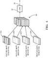
- Fig. 4 an embodiment of the fusion network 34 is illustrated from the viewpoint of operation.
- the second feature maps 20'a to 20'd (cf. Fig. 2 ) are stacked together, which gives a stack 62.
- This stack can be interpreted as a matrix or tensor matrix.
- the stack 62 is then processed by means of a convolutional network 34', with the fused data set 35 forming the output.
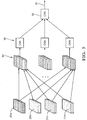
- the network structure illustrated in Fig. 5 can be used for implementing the fusion network 34.
- the second feature maps 20'a to 20'd are first grouped per feature type giving a plurality of stacks 64, each of the stack 64 comprising the second feature maps that correspond to one of the features.
- the stacks 64 are then processed individually by means of convolutional neural networks (CNNs) 66, the outputs of which are then stacked together and processed by means of a further convolutional neural network 66'.
- the output of the neural network 66' is the fused feature map 35.
- CNNs convolutional neural networks
Landscapes
- Engineering & Computer Science (AREA)
- Physics & Mathematics (AREA)
- Theoretical Computer Science (AREA)
- General Physics & Mathematics (AREA)
- Evolutionary Computation (AREA)
- Remote Sensing (AREA)
- Radar, Positioning & Navigation (AREA)
- Artificial Intelligence (AREA)
- Computer Vision & Pattern Recognition (AREA)
- Software Systems (AREA)
- General Health & Medical Sciences (AREA)
- Health & Medical Sciences (AREA)
- Computing Systems (AREA)
- Data Mining & Analysis (AREA)
- Multimedia (AREA)
- Computer Networks & Wireless Communication (AREA)
- Life Sciences & Earth Sciences (AREA)
- General Engineering & Computer Science (AREA)
- Databases & Information Systems (AREA)
- Medical Informatics (AREA)
- Biomedical Technology (AREA)
- Mathematical Physics (AREA)
- Molecular Biology (AREA)
- Computational Linguistics (AREA)
- Biophysics (AREA)
- Bioinformatics & Cheminformatics (AREA)
- Evolutionary Biology (AREA)
- Bioinformatics & Computational Biology (AREA)
- Electromagnetism (AREA)
- Signal Processing (AREA)
- Fuzzy Systems (AREA)
- Computational Mathematics (AREA)
- Automation & Control Theory (AREA)
- Mathematical Analysis (AREA)
- Mathematical Optimization (AREA)
- Pure & Applied Mathematics (AREA)
- Image Analysis (AREA)
- Traffic Control Systems (AREA)
- Image Processing (AREA)
Priority Applications (3)
| Application Number | Priority Date | Filing Date | Title |
|---|---|---|---|
| EP19160260.6A EP3702802A1 (fr) | 2019-03-01 | 2019-03-01 | Procédé de fusion de données multicapteurs |
| US16/801,296 US11552778B2 (en) | 2019-03-01 | 2020-02-26 | Method of multi-sensor data fusion |
| CN202010128041.4A CN111639663B (zh) | 2019-03-01 | 2020-02-28 | 多传感器数据融合的方法 |
Applications Claiming Priority (1)
| Application Number | Priority Date | Filing Date | Title |
|---|---|---|---|
| EP19160260.6A EP3702802A1 (fr) | 2019-03-01 | 2019-03-01 | Procédé de fusion de données multicapteurs |
Publications (1)
| Publication Number | Publication Date |
|---|---|
| EP3702802A1 true EP3702802A1 (fr) | 2020-09-02 |
Family
ID=65817715
Family Applications (1)
| Application Number | Title | Priority Date | Filing Date |
|---|---|---|---|
| EP19160260.6A Pending EP3702802A1 (fr) | 2019-03-01 | 2019-03-01 | Procédé de fusion de données multicapteurs |
Country Status (3)
| Country | Link |
|---|---|
| US (1) | US11552778B2 (fr) |
| EP (1) | EP3702802A1 (fr) |
| CN (1) | CN111639663B (fr) |
Cited By (4)
| Publication number | Priority date | Publication date | Assignee | Title |
|---|---|---|---|---|
| CN112149550A (zh) * | 2020-09-21 | 2020-12-29 | 华南理工大学 | 一种基于多传感器融合的自动驾驶车辆3d目标检测方法 |
| EP3943970A1 (fr) * | 2020-07-24 | 2022-01-26 | Aptiv Technologies Limited | Procédés et systèmes de détection d'objets situés à proximité d'un véhicule |
| US11327178B2 (en) * | 2019-09-06 | 2022-05-10 | Volvo Car Corporation | Piece-wise network structure for long range environment perception |
| US11789144B2 (en) | 2021-12-09 | 2023-10-17 | Aptiv Technologies Limited | Method for determining the mobility status of a target object |
Families Citing this family (6)
| Publication number | Priority date | Publication date | Assignee | Title |
|---|---|---|---|---|
| CN112233182A (zh) * | 2020-12-15 | 2021-01-15 | 北京云测网络科技有限公司 | 一种多激光雷达的点云数据的标注方法和装置 |
| CN112887262B (zh) * | 2020-12-28 | 2021-11-23 | 北京航空航天大学 | 一种基于多源信息融合的汽车信息安全防护方法及装置 |
| CN112906665A (zh) * | 2021-04-06 | 2021-06-04 | 北京车和家信息技术有限公司 | 交通标线融合方法、装置、存储介质及电子设备 |
| CN113392882B (zh) * | 2021-05-28 | 2022-04-26 | 中国人民解放军海军工程大学 | 一种主被动传感器抗差数据关联方法 |
| CN113326896A (zh) * | 2021-06-25 | 2021-08-31 | 国网上海市电力公司 | 一种基于多类型传感器的融合感知方法 |
| CN114419605B (zh) * | 2022-03-29 | 2022-07-19 | 之江实验室 | 基于多网联车空间对齐特征融合的视觉增强方法及系统 |
Citations (1)
| Publication number | Priority date | Publication date | Assignee | Title |
|---|---|---|---|---|
| EP3438872A1 (fr) * | 2017-08-04 | 2019-02-06 | Bayerische Motoren Werke Aktiengesellschaft | Procédé, appareil et programme informatique pour véhicule |
Family Cites Families (14)
| Publication number | Priority date | Publication date | Assignee | Title |
|---|---|---|---|---|
| GB0212748D0 (en) * | 2002-05-31 | 2002-07-10 | Qinetiq Ltd | Feature mapping between data sets |
| US9547894B2 (en) * | 2013-10-08 | 2017-01-17 | Toshiba Medical Systems Corporation | Apparatus for, and method of, processing volumetric medical image data |
| US11204610B2 (en) * | 2016-05-30 | 2021-12-21 | Kabushiki Kaisha Toshiba | Information processing apparatus, vehicle, and information processing method using correlation between attributes |
| DE102016213893A1 (de) * | 2016-07-28 | 2018-02-01 | Robert Bosch Gmbh | Verfahren und Vorrichtung zum Bestimmen der Absolutposition eines Kraftfahrzeugs, Ortsbestimmungssystem, Kraftfahrzeug |
| US10317901B2 (en) * | 2016-09-08 | 2019-06-11 | Mentor Graphics Development (Deutschland) Gmbh | Low-level sensor fusion |
| US11151447B1 (en) * | 2017-03-13 | 2021-10-19 | Zoox, Inc. | Network training process for hardware definition |
| US10593042B1 (en) * | 2017-04-11 | 2020-03-17 | Zoox, Inc. | Perspective conversion for multi-dimensional data analysis |
| US10509947B1 (en) * | 2017-04-11 | 2019-12-17 | Zoox, Inc. | Converting multi-dimensional data for image analysis |
| CN110832349B (zh) * | 2017-05-15 | 2023-10-10 | 奥斯特公司 | 全景彩色lidar系统和用于lidar系统的方法 |
| CN107918386B (zh) * | 2017-10-25 | 2021-01-01 | 北京汽车集团有限公司 | 用于车辆的多传感器数据融合方法、装置及车辆 |
| DE102017011329A1 (de) * | 2017-12-08 | 2018-07-05 | Daimler Ag | Signalverarbeitungsanordnung und Verfahren zum Betrieb eines Fahrzeugs |
| US11157527B2 (en) * | 2018-02-20 | 2021-10-26 | Zoox, Inc. | Creating clean maps including semantic information |
| CN108663677A (zh) * | 2018-03-29 | 2018-10-16 | 上海智瞳通科技有限公司 | 一种多传感器深度融合提高目标检测能力的方法 |
| CN109085570A (zh) * | 2018-06-10 | 2018-12-25 | 南京理工大学 | 基于数据融合的车辆检测跟踪算法 |
-
2019
- 2019-03-01 EP EP19160260.6A patent/EP3702802A1/fr active Pending
-
2020
- 2020-02-26 US US16/801,296 patent/US11552778B2/en active Active
- 2020-02-28 CN CN202010128041.4A patent/CN111639663B/zh active Active
Patent Citations (1)
| Publication number | Priority date | Publication date | Assignee | Title |
|---|---|---|---|---|
| EP3438872A1 (fr) * | 2017-08-04 | 2019-02-06 | Bayerische Motoren Werke Aktiengesellschaft | Procédé, appareil et programme informatique pour véhicule |
Non-Patent Citations (2)
| Title |
|---|
| SCHLOSSER JOEL ET AL: "Fusing LIDAR and images for pedestrian detection using convolutional neural networks", 2016 IEEE INTERNATIONAL CONFERENCE ON ROBOTICS AND AUTOMATION (ICRA), IEEE, 16 May 2016 (2016-05-16), pages 2198 - 2205, XP032908393, DOI: 10.1109/ICRA.2016.7487370 * |
| YU CHUNLEI ET AL: "An evidential sensor model for Velodyne scan grids", 2014 13TH INTERNATIONAL CONFERENCE ON CONTROL AUTOMATION ROBOTICS & VISION (ICARCV), IEEE, 10 December 2014 (2014-12-10), pages 583 - 588, XP032749159, DOI: 10.1109/ICARCV.2014.7064369 * |
Cited By (5)
| Publication number | Priority date | Publication date | Assignee | Title |
|---|---|---|---|---|
| US11327178B2 (en) * | 2019-09-06 | 2022-05-10 | Volvo Car Corporation | Piece-wise network structure for long range environment perception |
| EP3943970A1 (fr) * | 2020-07-24 | 2022-01-26 | Aptiv Technologies Limited | Procédés et systèmes de détection d'objets situés à proximité d'un véhicule |
| CN112149550A (zh) * | 2020-09-21 | 2020-12-29 | 华南理工大学 | 一种基于多传感器融合的自动驾驶车辆3d目标检测方法 |
| CN112149550B (zh) * | 2020-09-21 | 2023-01-06 | 华南理工大学 | 一种基于多传感器融合的自动驾驶车辆3d目标检测方法 |
| US11789144B2 (en) | 2021-12-09 | 2023-10-17 | Aptiv Technologies Limited | Method for determining the mobility status of a target object |
Also Published As
| Publication number | Publication date |
|---|---|
| US20200280429A1 (en) | 2020-09-03 |
| US11552778B2 (en) | 2023-01-10 |
| CN111639663A (zh) | 2020-09-08 |
| CN111639663B (zh) | 2024-04-12 |
Similar Documents
| Publication | Publication Date | Title |
|---|---|---|
| US11552778B2 (en) | Method of multi-sensor data fusion | |
| CN110988912B (zh) | 自动驾驶车辆的道路目标与距离检测方法、系统、装置 | |
| US20210390329A1 (en) | Image processing method, device, movable platform, unmanned aerial vehicle, and storage medium | |
| US10817752B2 (en) | Virtually boosted training | |
| WO2020094033A1 (fr) | Procédé et système de conversion de données de nuage de points destinées à être utilisées avec des réseaux neuronaux convolutifs 2d | |
| CN113412505B (zh) | 用于对通过探测和测距传感器获得的点云进行有序表示和特征提取的处理单元和方法 | |
| CN104833370A (zh) | 用于映射、定位和位姿校正的系统和方法 | |
| CN112802078A (zh) | 深度图生成方法和装置 | |
| CN115049700A (zh) | 一种目标检测方法及装置 | |
| CN113970922A (zh) | 点云数据的处理方法、智能行驶控制方法及装置 | |
| EP3509036B1 (fr) | Procédé de détermination de position et d'attitude et système utilisant des images de bord | |
| CN113111751A (zh) | 一种自适应融合可见光与点云数据的三维目标检测方法 | |
| Patra et al. | A joint 3d-2d based method for free space detection on roads | |
| CN111681172A (zh) | 协同构建点云地图的方法、设备和系统 | |
| CN110992424A (zh) | 基于双目视觉的定位方法和系统 | |
| CN113012191B (zh) | 一种基于点云多视角投影图的激光里程计算法 | |
| US20220292289A1 (en) | Systems and methods for depth estimation in a vehicle | |
| CN114155414A (zh) | 面向无人驾驶的新型特征层数据融合的方法、系统及目标检测方法 | |
| US20210165093A1 (en) | Vehicles, Systems, and Methods for Determining an Entry of an Occupancy Map of a Vicinity of a Vehicle | |
| Karantzalos et al. | Model-based building detection from low-cost optical sensors onboard unmanned aerial vehicles | |
| CN116129234A (zh) | 一种基于注意力的4d毫米波雷达与视觉的融合方法 | |
| CN115407338A (zh) | 一种车辆环境信息感知方法及系统 | |
| Velat et al. | Vision based vehicle localization for autonomous navigation | |
| EP4036859A1 (fr) | Système et procédé pour fournir des données de référence géocodées améliorées à une représentation de carte 3d | |
| Danescu | Obstacle detection using dynamic Particle-Based occupancy grids |
Legal Events
| Date | Code | Title | Description |
|---|---|---|---|
| PUAI | Public reference made under article 153(3) epc to a published international application that has entered the european phase |
Free format text: ORIGINAL CODE: 0009012 |
|
| STAA | Information on the status of an ep patent application or granted ep patent |
Free format text: STATUS: THE APPLICATION HAS BEEN PUBLISHED |
|
| AK | Designated contracting states |
Kind code of ref document: A1 Designated state(s): AL AT BE BG CH CY CZ DE DK EE ES FI FR GB GR HR HU IE IS IT LI LT LU LV MC MK MT NL NO PL PT RO RS SE SI SK SM TR |
|
| AX | Request for extension of the european patent |
Extension state: BA ME |
|
| STAA | Information on the status of an ep patent application or granted ep patent |
Free format text: STATUS: REQUEST FOR EXAMINATION WAS MADE |
|
| 17P | Request for examination filed |
Effective date: 20210302 |
|
| RBV | Designated contracting states (corrected) |
Designated state(s): AL AT BE BG CH CY CZ DE DK EE ES FI FR GB GR HR HU IE IS IT LI LT LU LV MC MK MT NL NO PL PT RO RS SE SI SK SM TR |
|
| STAA | Information on the status of an ep patent application or granted ep patent |
Free format text: STATUS: EXAMINATION IS IN PROGRESS |
|
| 17Q | First examination report despatched |
Effective date: 20220601 |
|
| RAP3 | Party data changed (applicant data changed or rights of an application transferred) |
Owner name: APTIV TECHNOLOGIES LIMITED |
|
| RAP1 | Party data changed (applicant data changed or rights of an application transferred) |
Owner name: APTIV TECHNOLOGIES AG |