EP3702751A1 - Operating-status diagnostic apparatus - Google Patents
Operating-status diagnostic apparatus Download PDFInfo
- Publication number
- EP3702751A1 EP3702751A1 EP20170272.7A EP20170272A EP3702751A1 EP 3702751 A1 EP3702751 A1 EP 3702751A1 EP 20170272 A EP20170272 A EP 20170272A EP 3702751 A1 EP3702751 A1 EP 3702751A1
- Authority
- EP
- European Patent Office
- Prior art keywords
- heat flux
- sensor
- heat
- flux sensor
- warming
- Prior art date
- Legal status (The legal status is an assumption and is not a legal conclusion. Google has not performed a legal analysis and makes no representation as to the accuracy of the status listed.)
- Withdrawn
Links
Images



Classifications
-
- G—PHYSICS
- G01—MEASURING; TESTING
- G01M—TESTING STATIC OR DYNAMIC BALANCE OF MACHINES OR STRUCTURES; TESTING OF STRUCTURES OR APPARATUS, NOT OTHERWISE PROVIDED FOR
- G01M99/00—Subject matter not provided for in other groups of this subclass
- G01M99/002—Thermal testing
-
- G—PHYSICS
- G01—MEASURING; TESTING
- G01K—MEASURING TEMPERATURE; MEASURING QUANTITY OF HEAT; THERMALLY-SENSITIVE ELEMENTS NOT OTHERWISE PROVIDED FOR
- G01K17/00—Measuring quantity of heat
- G01K17/06—Measuring quantity of heat conveyed by flowing media, e.g. in heating systems e.g. the quantity of heat in a transporting medium, delivered to or consumed in an expenditure device
- G01K17/08—Measuring quantity of heat conveyed by flowing media, e.g. in heating systems e.g. the quantity of heat in a transporting medium, delivered to or consumed in an expenditure device based upon measurement of temperature difference or of a temperature
- G01K17/20—Measuring quantity of heat conveyed by flowing media, e.g. in heating systems e.g. the quantity of heat in a transporting medium, delivered to or consumed in an expenditure device based upon measurement of temperature difference or of a temperature across a radiating surface, combined with ascertainment of the heat-transmission coefficient
-
- G—PHYSICS
- G01—MEASURING; TESTING
- G01M—TESTING STATIC OR DYNAMIC BALANCE OF MACHINES OR STRUCTURES; TESTING OF STRUCTURES OR APPARATUS, NOT OTHERWISE PROVIDED FOR
- G01M13/00—Testing of machine parts
- G01M13/02—Gearings; Transmission mechanisms
Definitions
- the present invention relates to an operating-status diagnostic apparatus which diagnoses an operating status of a facility.
- a heat flux sensor which detects heat fluxes is disclosed in, for example, PTL 1.
- a warming-up operation for raising the temperature of the facility is performed from immediately after the start of operation until the facility is stabilized.
- the operating status of the facility is switched from the warming-up operation to a steady-state operation.
- the steady-state operation is operation of the facility in the stabilized state. In other words, the steady-state operation is operation in a state where the facility can fully deliver its inherent performance.
- warming-up operation is desirably switched to steady-state operation immediately when the warming-up is completed. To achieve this, it is necessary to be able to appropriately determine whether or not the facility is in a warming-up complete state where the warming-up has completed.
- An object of the present invention is to provide an operating-status diagnostic apparatus which can appropriately determine whether or not the facility is in the warming-up complete state.
- a first aspect according to an operating-status diagnostic apparatus is an operating-status diagnostic apparatus diagnosing an operating status of a facility, the apparatus including a sensor unit detecting heat fluxes flowing outward from a component of the facility and a control unit determining whether or not the operating status of the facility indicates that the component is in a warming-up complete state where warming-up of the component is completed, based on a detection result of detection by the sensor unit.
- a change tendency of heat fluxes varies between a warming-up period and a period in a warming-up complete state.
- the diagnostic apparatus of the present invention can determine whether or not the component is in the warming-up complete state.
- an operating-status diagnostic apparatus 1 diagnoses a warming-up complete status of a workpiece feeding apparatus 300.
- the workpiece feeding apparatus 300 is installed in a production facility where a workpiece W1, which corresponds to a machining object, is machined.
- the workpiece feeding apparatus 300 includes a linear movement mechanism M1 with a ball screw 301, and a robot M2.
- the workpiece feeding apparatus 300 transfers the workpiece W1 using the linear movement mechanism M1 and the robot M2.
- the linear movement mechanism M1 transfers the workpiece W1 in a direction D1.
- the robot M2 transfers the workpiece W1 in a direction D2, a direction D3, and the like.
- the robot M2 transfers the workpiece W1 to a pedestal 304 of the linear movement mechanism M1.
- the robot M2 mounts the workpiece W1 on the pedestal 304.
- the linear movement mechanism M1 transfers the mounted workpiece W1.
- the linear movement mechanism M1 includes a ball screw 301, support members 302, a motor 303, the pedestal 304, rails 305, and guide blocks 306.
- the support members 302 are omitted for easier understanding.
- the ball screw 301 is a component of the workpiece feeding apparatus 300.
- the ball screw 301 is a mechanical component which converts a rotary motion into a linear motion.
- the ball screw 301 has a screw shaft 311, a nut 312, and balls 313.
- Balls 313 are arranged between the screw shaft 311 and the nut 312. Rotation of the screw shaft 311 allows the nut 312 to move linearly.
- Each of the support members 302 supports a corresponding one of axially opposite ends of the screw shaft 311.
- the motor 303 is a power source which rotates the screw shaft 311.
- the pedestal 304 is a component on which the workpiece W1 is mounted.
- the pedestal 304 appears, in plan view, as a rectangle having a longitudinal direction orthogonal to the axial direction of the screw shaft 311 (that is, an up-down direction in Fig. 1 ).
- a longitudinally approximately central portion of the pedestal 304 is coupled to the nut 312. Longitudinally opposite ends of the pedestal 304 are coupled to the respective guide blocks 306.
- the rails 305 are linear members.
- the two rails 305 are used and fixed to a base plate 307 as illustrated in Fig. 3 .
- the guide blocks 306 are engaged with the respective rails.
- the guide blocks 306 serve as guide members which move along the respective rails 305.
- the diagnostic apparatus 1 includes a sensor unit 2 and a control apparatus 3.
- the sensor unit 2 detects heat fluxes flowing outward from the ball screw 301.
- the sensor unit 2 outputs a sensor signal corresponding to heat fluxes flowing outward from the ball screw 301 to the control apparatus 3.
- the sensor unit 2 is attached to a surface of the nut 312. Details of a structure of the sensor unit 2 will be described below.
- the sensor unit 2 is connected to an input side of the control apparatus 3.
- the control apparatus 3 diagnoses an operating status of the ball screw 301. In this diagnosis, whether or not the operating status of the ball screw 301 indicates that the ball screw 301 is in a warming-up complete state is determined based on a detection result from the sensor unit 2. Therefore, the control apparatus 3 constitutes a control unit which determines, based on the detection result from the heat flux sensor 10, whether or not the operating status of a facility indicates that a component of the facility is in the warming-up complete state, where the warming-up of the component is completed.
- the motor 303 which serves as driving equipment for the workpiece feeding apparatus 300, and the robot M2 are connected to an output side of the control apparatus 3.
- the control apparatus 3 controls operation of the workpiece feeding apparatus 300 based on the diagnosis result.
- the control apparatus 3 is configured to have a microcomputer and a storage apparatus.
- the sensor unit 2 includes two heat flux sensors 10, a thermal buffer 11, and a heat sink 12.
- the two heat flux sensors 10, the thermal buffer 11, and the heat sink 12 are all shaped like flat plates.
- the two heat flux sensors 10 have the same internal structure. One of the two heat flux sensors 10 is a first heat flux sensor 10a. Another one of the two heat flux sensors 10 is a second heat flux sensor 10b.
- the first heat flux sensor 10a is arranged in contact with an outer surface of the nut 312.
- the second heat flux sensor 10b is arranged on a side far from the nut 312 with respect to the first heat flux sensor 10a.
- the thermal buffer 11 is arranged between the first heat flux sensor 10a and the second heat flux sensor 10b.
- the heat sink 12 is arranged on the side far from the nut 312 with respect to the second heat flux sensor 10b. That is, in the sensor unit 2, the first heat flux sensor 10a, the thermal buffer 11, the second heat flux sensor 10b, and the heat sink 12 are arranged in this order from the side close to the nut 312 toward the side far from the nut 312.
- the first heat flux sensor 10a outputs a first sensor signal corresponding to a heat flux passing through the first heat flux sensor 10a from the nut 312 side thereof toward the thermal buffer 11 side thereof.
- the second heat flux sensor 10b outputs a second sensor signal corresponding to a heat flux passing through the second heat flux sensor 10b from the thermal buffer 11 side thereof toward the side opposite to the thermal buffer 11 side.
- the first heat flux sensor 10a and the second heat flux sensor 10b appears, in plan view, as rectangles which are the same in shape and size.
- the thermal buffer 11 has a predetermined heat capacity.
- the thermal buffer 11 is formed of a metal material or a resin material.
- the thermal buffer 11 has a material and a thickness set to provide a heat capacity which allows detection of changes in heat fluxes dissipated outward from the nut 312 as described below.
- the thermal buffer 11 has a planar shape that is the same as the planar shape of the first heat flux sensor 10a in form and size.
- the thermal buffer 11 may have a planar shape that is different from the planar shape of the first heat flux sensor 10a in form and size.
- the heat sink 12 has a predetermined heat capacity.
- the heat sink 12 is formed of a metal material or a resin material.
- the heat sink 12 has a material and a thickness set to provide a larger heat capacity than the thermal buffer 11.
- the heat sink 12 is configured to have a larger planar shape than the first heat flux sensor 10a, the thermal buffer 11, and the second heat flux sensor 10b.
- the heat sink 12 is fixed to the nut 312 with the first heat flux sensor 10a, the thermal buffer 11, and the second heat flux sensor 10b all sandwiched between the heat sink 12 and the nut 312.
- threaded holes are formed in an outer circumferential portion of the heat sink 12.
- the heat sink 12 is fixed to the nut 312 by screws 13 inserted into the threaded holes.
- Spacers 14 are arranged between the nut 312 and the heat sink 12. The screws 13 penetrate the respective spacers 14.
- each of the heat flux sensors 10 includes an insulating substrate 100, a front surface protecting member 110, and a back surface protecting member 120, which are integrated together, and first and second thermoelectric members 130, 140 are alternately and serially connected together inside the integrated components 100, 110, and 120.
- the surface protecting member 110 is omitted.
- the insulating material 100, the front surface protecting member 110, and the back surface protecting member 120 are formed like films and constituted of a flexible resin material such as a thermoplastic resin.
- the insulating substrate 100 has a plurality of first via holes 101 and a plurality of second via holes 102 formed therein in such a manner as to penetrate the insulating substrate 100 in a thickness direction thereof.
- First thermoelectric members 130 and second thermoelectric members 140 are embedded in the first and second via holes 101, 102, respectively.
- a front surface conductor pattern 111 arranged on a front surface 100a of the insulating substrate 100, constitutes a one-side connection portion between each of the first thermoelectric members 130 and the corresponding second thermoelectric member 140.
- a back surface conductor pattern 121 arranged on a back surface 100b of the insulating substrate 100, constitutes an other-side connection portion between each of the first thermoelectric members 130 and the corresponding second thermoelectric member 140.
- thermoelectromotive force is generated in the first and second thermoelectric members 130, 140 due to the Seebeck effect.
- the heat flux sensor 10 outputs the thermoelectromotive force, specifically, a voltage, as a sensor signal.
- the first heat flux sensor 10a and the second heat flux sensor 10b are configured to output sensor signals with the same absolute value when heat fluxes passing through the respective heat flux sensors are of the same magnitude.
- the first heat flux sensor 10a and the second heat flux sensor 10b connected together in series, are electrically connected to the control apparatus 3.
- the first heat flux sensor 10a and the second heat flux sensor 10b are arranged such that, when heat fluxes from the nut 312 pass through the first heat flux sensor 10a and the second heat flux sensor 10b in this order, the heat flux sensors 10a and 10b output a first sensor signal and a second sensor signal, respectively, which have an opposite polarity relation.
- the first and second heat flux sensors 10a, 10b are arranged such that the front surface protecting members 110 thereof lie opposite to each other.
- the front surface conductor patterns 111 of the first and second heat flux sensors 10a, 10b are connected together via external wiring 151.
- the back surface conductor patterns 121 of the first and second heat flux sensors 10a, 10b are connected to the control apparatus 3 via external wiring 152.
- each of the first and second heat flux sensors 10b, 10b outputs a positive sensor signal when a heat flux passes from the back surface protecting member 120 side toward the front surface protecting member 110 side.
- the first heat flux sensor 10a outputs a positive sensor signal
- the second heat flux sensor 10b outputs a negative sensor signal.
- the sensor unit 2 outputs a sensor signal that is a combination of the first sensor signal and the second sensor signal to the control apparatus 3.
- a sensor signal that is a combination of the first sensor signal and the second sensor signal to the control apparatus 3.
- the control apparatus 3 performs a warming-up operation when the operation of the workpiece feeding apparatus 300 is started.
- the warming-up operation is intended to raise the temperature of the ball screw 301 from immediately after the start of the operation of the workpiece feeding apparatus 300.
- the linear movement mechanism M1 is operated with no workpiece W1 mounted thereon.
- the motor 303 of the linear movement mechanism M1 is driven with the robot M2 being not driven.
- the control apparatus 3 performs a steady-state operation after the warming-up of the ball screw 301 is completed.
- the steady-state operation is an operation performed with the ball screw 301 stabilized.
- the workpiece W1 mounted on the pedestal 304 is transferred.
- the motor 303 for the robot M2 and the linear movement mechanism M1 is driven.
- the reason why the warming-up operation is performed is as described below.
- frictional heat generated by the balls 312 inside the nut 312 is not dissipated but is accumulated in the nut 312. Consequently, the temperature of the ball screw 301 rises.
- the rise in the temperature of the ball screw 301 causes the ball screw 301 to be thermally expanded.
- the pedestal 304 is stopped at a less accurate stop position. As a result, the workpiece W1 is inappropriately transferred. Moreover, the workpiece W1 is inappropriately machined.
- the moving distance of the nut 312 depends on the rotation speed of the screw shaft 311.
- the rotation speed of the screw shaft 311 is set to allow the pedestal 304 to stop at a predetermined position.
- the moving distance of the nut 312 varies even with the rotation speed of the screw shaft 311 remaining the same.
- the stop position of the pedestal 304 varies. If the workpiece W1 is machined at a position to which the workpiece W1 has been transferred, the workpiece W1 is precluded from being machined when the stop position is different from the predetermined position.
- the warming-up operation is performed until the ball screw 301 is stabilized. Once the warming-up is completed, the operation is switched to the steady-state operation. Consequently, the workpiece W1 is restrained from being inappropriately transferred.
- the linear movement mechanism M1 repeats operation cycles each including operation and stoppage of the ball screw 301.
- the frictional heat generated by the balls 313 is dissipated from the nut 312, thus increasing an output value of the sensor unit 2.
- no frictional heat is generated, thus reducing the output value of the sensor unit 2. Consequently, the output value of the sensor unit 2 is increased or reduced depending on the operation cycle both during a warming-up state where the ball screw 301 is being warmed up and during a warming-up complete state where the warming-up is completed.
- the frictional heat is accumulated in the nut 312.
- the temperature inside the nut 312 rises earlier than the temperature outside the nut 312.
- a smaller amount of heat is dissipated outward from the nut 312 than in the warming-up complete state.
- the sensor unit 2 has a waveform rising over time as illustrated in Fig. 7 .
- the sensor unit 2 has an output waveform indicative of an output value which is larger than the output value during the warming-up state and which increases and decreases by an approximately constant magnitude as illustrated in Fig. 7 .
- Stoppage of the ball screw 301 causes the heat accumulated in the nut 312 to be dissipated.
- the ball screw 301 is operated during the heat dissipation. That is, the ball screw 301 is operated in such operation cycles as allowing a certain amount of heat to be accumulated in the nut 312.
- the sensor unit 2 has a larger output value in the warming-up complete state than in the warming-up state in spite of the provision of the stoppage period for the ball screw 301.
- a threshold is preset which is used to determine whether or not the ball screw 301 is in the warming-up complete state, to allow the output value of the sensor unit 2 to be compared with the threshold. This enables determination of whether or not the ball screw 301 is in the warming-up complete state.
- the control apparatus 3 diagnoses the operating status of the ball screw 301 based on a detection result from the sensor unit 2 as illustrated in Fig. 8 .
- the switching control is performed when the warming-up operation of the workpiece feeding apparatus 300 is started.
- Steps illustrated in Fig. 8 constitute a function implementing unit that implements various functions.
- the control apparatus 3 acquires a detected value from the sensor unit 2.
- the output value Specifically, the voltage value
- the control apparatus 3 acquires a corrected value corresponding to the corrected output value, as the detected value.
- step S2 the control apparatus 3 compares the detected value with the threshold pre-stored in the storage apparatus to determine whether or not the detected value is larger than the threshold.
- step S1 the control apparatus 3 acquires a plurality of detected values for different elapsed times from the start of the warming-up operation.
- step S2 the control apparatus 3 preferably determines whether or not all of the plurality of detected values are larger than the threshold.
- step S2 if the detected value is smaller than the threshold, the control apparatus 3 makes a negative determination to end the control processing illustrated in the flowchart in Fig. 8 . The control apparatus 3 then executes step S1 again.
- step S3 the control apparatus 3 switches the operating status of the workpiece feeding apparatus 300 from the warming-up operation to the steady-state operation. Consequently, the workpiece W1 is transferred by the linear movement mechanism M1 and the robot M2. Then, machining of the workpiece W1 is started.
- the diagnostic apparatus 1 of the present embodiment can appropriately determine whether or not the operating status of the ball screw 301 indicates that the ball screw 301 is in a warming-up complete state.
- the sensor unit 2 includes the thermal buffer 11 between the first heat flux sensor 10a and the second heat flux sensor 10b.
- the control apparatus 3 determines whether or not the ball screw 301 is in the warming-up complete state based on the first sensor signal output by the first heat flux sensor 10a and the second sensor signal output by the second heat flux sensor 10b.
- the thermal buffer 11 accumulates and dissipates heat.
- the heat flux passing through the second heat flux sensor 10b changes later and more slowly than the heat flux passing through the first heat flux sensor 10a does. Therefore, a difference between the first sensor signal and the second sensor signal allows a change in the heat fluxes dissipated from the nut 312 to be detected.
- the single heat flux sensor 10 may exclusively be used to detect the heat fluxes dissipated from the nut 312.
- the heat fluxes passing through the heat flux sensor 10 also changes under the effect of the environmental temperature. Specifically, even with the same amount of heat generated inside the nut 312, the heat fluxes passing through the heat flux sensor 10 have a larger magnitude when the environmental temperature is low than when the environmental temperature is high. Even with the same amount of heat generated inside the nut 312, the heat fluxes passing through the heat flux sensor 10 have a smaller magnitude when the environmental temperature is high than when the environmental temperature is low.
- the control apparatus 3 erroneously determines that the ball screw 301 is in the warming-up complete state though the ball screw 301 is actually in the warming-up state.
- the control apparatus 3 erroneously determines that the ball screw 301 is in the warming-up complete state though the ball screw 301 is actually in the warming-up state.
- the output value of the sensor unit 2 may not exceed the threshold even if the ball screw 301 is in the warming-up complete state. In this case, the control apparatus 3 erroneously determines that the ball screw 301 is in the warming-up state though the ball screw 301 is actually in the warming-up complete state.
- the first heat flux sensor 10a and the second heat flux sensor 10b of the sensor unit 2 of the present embodiment are arranged on the opposite sides of the thermal buffer 11. Therefore, the first heat flux sensor 10a and the second heat flux sensor 10b are arranged relatively close to each other. Furthermore, the environmental temperature around the sensor unit 2 typically varies slowly over a long period of one day. Thus, even though the thermal buffer 11 is arranged between the first heat flux sensor 10a and the second heat flux sensor 10b, the first heat flux sensor 10a and the second heat flux sensor 10b are subjected to the same or substantially the same effect of the environmental temperature. Each of the first heat flux sensor 10a and the second heat flux sensor 10b outputs a sensor signal corresponding to the heat flux subjected to the same effect of the environmental temperature.
- Outputs from the first heat flux sensor 10a and the second heat flux sensor 10b have the same absolute value for the same magnitude of the heat flux. Therefore, the use of the sum of the outputs from the first heat flux sensor 10a and the second heat flux sensor 10b allows elimination (that is, cancellation) of the effect of the environmental temperature on the detection result from the sensor unit 2.
- the output waveform of the sensor unit 2 in the warming-up complete state is free from the effect of the environmental temperature as illustrated in Fig. 7 . This allows avoidance of erroneous determination caused by a variation in the environmental temperature during a single day.
- the diagnostic apparatus 1 of the present embodiment can accurately diagnose the warming-up complete status.
- the outputs from the first heat flux sensor 10a and the second heat flux sensor 10b do not necessarily have the same absolute value for the same magnitude of the heat flux.
- the outputs may have any absolute values as long as the absolute values are close to each other. Even in this case, the use of the sum of the outputs from the first heat flux sensor 10a and the second heat flux sensor 10b enables a reduction in the effect of the environmental temperature on the detection result from the sensor unit 2.
- the first heat flux sensor 10a and the second heat flux sensor 10b output the first sensor signal and the second sensor signal, respectively, which have an opposite polarity relation, when a heat flux from the nut 312 passes through the first heat flux sensor 10a and the second heat flux sensor 10b in this order.
- the first heat flux sensor 10a and the second heat flux sensor 10b connected together in series, are electrically connected to the control apparatus 3. Consequently, a sensor signal corresponding to a combination of the first sensor signal and the second sensor signal can be outputted from the sensor unit 2 toward the control apparatus 3. This allows omission of the calculation of the sum of the first sensor signal and the second sensor signal performed by the control apparatus 3. That is, the calculation processing executed by the control apparatus 3 can be simplified.
- the sensor unit 2 may be configured not to have the heat sink 12. However, if the sensor unit 2 does not have the heat sink 12, a front surface temperature of the second heat flux sensor 10b instantaneously changes, for example, because the front surface of the second heat flux sensor 10b is exposed to atmosphere. This affects the heat fluxes passing through the sensor unit 2. Thus, the sensor unit 2 has a reduced accuracy with which the heat fluxes are detected.
- the sensor unit 2 of the present embodiment includes the heat sink 12 having a predetermined heat capacity. Consequently, even if the front surface temperature of the sensor unit 2 varies in a short period of time, a possible variation in the temperature of the second heat flux sensor 10b can be suppressed from occurring by accumulation and dissipation of heat in and from the heat sink 12. Thus, the accuracy with which the sensor unit 2 detects the heat fluxes can be increased.
- the heat sink 12 is configured to have a larger heat capacity than the thermal buffer 11. Consequently, even when a large amount of heat is dissipated from the nut 312, the heat can be directed from the nut 312 toward the heat sink 12. Thus, heat can be prevented from being trapped inside the sensor unit 2.
- an operating-status diagnostic apparatus 1 diagnoses a warming-up complete status of an automatic cutting machine 400.
- the automatic cutting machine 400 includes a drill 401, a chuck unit 402 for the drill, and a chuck unit for a workpiece.
- the drill 401 is a cutting tool used for cutting.
- the chuck unit 402 for the drill is a holding unit which holds the drill 401.
- the chuck unit 403 for the workpiece is a holding unit which holds a workpiece W2, corresponding to a machining object.
- the automatic cutting machine 400 repeats machining and stoppage to machine a plurality of workpieces W2 one by one in this order. During machining, friction between the drill 401 and the workpiece W2 causes the drill 401 to generate heat. The heat generated by the drill 401 is dissipated outward from the chuck unit 402 of the drill.
- the diagnostic apparatus 1 includes the sensor unit 2 and the control apparatus 3.
- the sensor unit 2 is attached to a front surface of the chuck unit 402 for the drill.
- the sensor unit 2 detects heat fluxes flowing outward from the drill 401 via the chuck unit 402 for the drill.
- the sensor unit 2 outputs a sensor signal corresponding to heat fluxes flowing outward from the drill 401 via the chuck unit 402 for the drill to the control apparatus 3.
- a configuration of the sensor unit 2 is the same as the configuration of the sensor unit 2 of the first embodiment.
- the control apparatus 3 performs operation control for the automatic cutting machine 400 and diagnosis of the operating status of the drill 401.
- the control apparatus 3 performs a warming-up operation on the drill 401 when operation of the automatic cutting machine 400 is started.
- the warming-up operation is an operation for machining a workpiece for warming-up instead of the workpiece W2, intended for machining.
- the control apparatus 3 performs a steady-state operation after the warming-up operation for the drill 401.
- the steady-state operation is an operation for machining the workpiece W2, intended for machining.
- the drill 401 During a certain period from immediately after the start of operation of the automatic cutting machine 400, the drill 401 generates heat to raise the temperature of the drill 401. The rise in the temperature of the drill 401 causes the drill 401 to be thermally expanded. When the workpiece W2 is machined with the drill 401 continuously thermally expanding, machining accuracy decreases. Thus, the warming-up operation is performed until the drill 401 is stabilized. Once the warming-up is completed, the control apparatus 3 switches from the warming-up operation to the steady-state operation.
- the control apparatus 3 diagnoses the operating status of the drill 401. Specifically, the control apparatus 3 determines whether or not the operating status of the drill 401 indicates that the drill 401 is in a warming-up complete state based on a detection result from the sensor unit 2.
- Output waveforms obtained when the drill 401 is in the warming-up state and when the drill 401 is in the warming-up complete state are similar to the waveforms described in the first embodiment and illustrated in Fig. 7 .
- a threshold used to determine whether or not the drill 401 is in the warming-up complete state is pre-stored in the control apparatus 3. Then, the control apparatus 3 compares an output value of the sensor unit 2 with the threshold. Consequently, the control apparatus 3 can determine whether or not the drill 401 is in the warming-up complete state.
- the sensor unit 2 used for the diagnostic apparatus 1 has the same configuration as the sensor unit 2 of the first embodiment.
- the diagnostic apparatus 1 of the present embodiment produces effects similar to those of the diagnostic apparatus 1 of the first embodiment.
- the first heat flux sensor 10 may exclusively be used as the sensor unit 2 used for the diagnostic apparatus 1.
- the present embodiment corresponds to the first embodiment with the configuration of the sensor unit 2 being changed.
- the remaining part of the configuration of a diagnostic apparatus 1 of the present embodiment is the same as the corresponding part in the first embodiment.
- a sensor unit 2 of the present embodiment has a flat-plate-like heat receiver 16.
- the heat receiver 16 is arranged closer to a nut 312 than a first heat flux sensor 10a is. Therefore, the heat receiver 16 is arranged between the nut 312 and the first heat flux sensor 10a.
- the heat receiver 16 has a predetermined heat capacity.
- the heat receiver 16 is formed of a metal material or a resin material.
- the heat receiver 16 has a material and a thickness set to provide a smaller heat capacity than the thermal buffer 11 and the heat sink 12.
- the heat receiver 16 has a planar shape which is the same as the planar shape of the first heat flux sensor 10a in form and size.
- the planar shape of the heat receiver 16 may be different from the planar shape of the first heat flux sensor 10a in form and size.
- a possible short-time change in heat fluxes such as noise which is not intended to be detected can be restrained from affecting the first and second heat flux sensors 10a, 10b, based on accumulation and dissipation of heat in and from the heat receiver 16.
- the sensor unit 2 of the present embodiment a small heat capacity is set for the heat receiver 16.
- the sensor unit 2 of the present embodiment can detect changes in heat fluxes resulting from operation and stoppage of the ball screw 301 of which changes are intended to be detected. That is, in the sensor unit 2 of the present embodiment, the heat capacity of the heat receiver 16 is set to a magnitude at which the sensor unit 2 can detect changes in heat fluxes resulting from operation and stoppage of the ball screw 301.
- the diagnostic apparatus 1 of the present embodiment can accurately determine whether or not the ball screw 301 is in the warming-up complete state.
- the sensor unit 2 may be configured to have the heat receiver 16. Then, the second embodiment produces effects similar to those of the present embodiment.
- the present embodiment corresponds to the first embodiment with the configuration of the sensor unit 2 being changed.
- the remaining part of the configuration of a diagnostic apparatus 1 of the present embodiment is the same as the corresponding part in the first embodiment.
- the first and second heat flux sensors 10a, 10b are connected together via a bent shape portion 10c having a bent shape.
- the bent shape portion 10c is structured such that the insulating substrate 100, the front surface protecting member 110, and the back surface protecting member 120 are laid on top of one another. Consequently, in the sensor unit 2 of the present embodiment, the first and second heat flux sensors 10a, 10b are integrated together.
- the sensor unit 2 of the present embodiment is structured such that the single heat flux sensor 10 is bent in such a manner as to enclose the thermal buffer 11.
- each of the insulating substrate 100, the front surface protecting member 110, and the back surface protecting member 120 is formed of a flexible resin material as described above.
- the heat flux sensor 10 can be easily bent. This results in implementation of the configuration where the thermal buffer 11 is arranged between the first heat flux sensor 10a and the second heat flux sensor 10b.
- the back surface conductor patterns 121 thereof are connected together.
- the first and second heat flux sensors 10a, 10b are electrically connected together using a wiring pattern inside the heat flux sensor 10 instead of the external wiring 151.
- the front surface conductor patterns thereof may be connected together.
- the first and second heat flux sensors 10a, 10b are configured as the single heat flux sensor 10, allowing omission of the external wiring 151 used for connecting the first heat flux sensor 10a and the second heat flux sensor 10b. Therefore, the number of components to be needed can be reduced.
- an operating-status diagnostic apparatus includes a sensor unit and a control unit.
- the sensor unit detects heat fluxes flowing outward from a component of a facility.
- the control unit determines whether or not an operating status of the facility indicates that the component is in a warming-up complete state where warming-up of the component is completed.
- the sensor unit has a first heat flux sensor, a second heat flux sensor, and a thermal buffer arranged between the first heat flux sensor and the second heat flux sensor.
- the first heat flux sensor outputs a first sensor signal corresponding to a heat flux passing through the first heat flux sensor.
- the second heat flux sensor outputs a second sensor signal corresponding to a heat flux passing through the second heat flux sensor.
- the control unit determines whether or not the component is in the warming-up complete state based on the first sensor signal and the second sensor signal.
- the thermal buffer is arranged between the first heat flux sensor and the second heat flux sensor in the sensor unit.
- the first heat flux sensor and the second heat flux sensor are arranged on the opposite sides of the thermal buffer and relatively close to each other.
- the environmental temperature which is the temperature of an environment where the sensor unit is installed, typically varies slowly over a long period of time.
- the first heat flux sensor and the second heat flux sensor are subjected to the same or substantially the same effect of the environmental temperature.
- Each of the first heat flux sensor and the second heat flux sensor outputs a sensor signal corresponding to the heat flux subjected to the same or substantially the same effect of the environmental temperature. Therefore, the use of the sensor signals from both heat flux sensors enables elimination or reduction of the effect of the environmental temperature on the detection result from the sensor unit. Therefore, the diagnostic apparatus of the second aspect can accurately diagnose the warming-up complete status.
- the sensor unit has a heat sink arranged farther from the component than the second heat flux sensor is and having a predetermined heat capacity.
- the heat sink is configured to have a larger heat capacity than the thermal buffer. Consequently, even when the component dissipates a large amount of heat, the heat can be passed from the component toward the heat sink. Thus, the heat can be prevented from being trapped inside the sensor unit.
- the sensor unit has a heat receiver arranged closer to the component than the first heat flux sensor is.
- the heat receiver is configured to have a smaller heat capacity than the thermal buffer.
- the first heat flux sensor and second heat flux sensor are arranged such that the first sensor signal and the second sensor signal have opposite polarities when heat fluxes from the component pass through the first heat flux sensor and the second heat flux sensor in this order.
- the first heat flux sensor and the second heat flux sensor are electrically connected together in series.
- the sensor unit can output a sensor signal corresponding to a combination of the first sensor signal and the second sensor signal. This enables elimination of the need for a calculation process for the sum of the first sensor signal and the second sensor signal.
- each of the first heat flux sensor and the second heat flux sensor is configured to have a flexible film-like insulating substrate, a plurality of first thermoelectric members, and a plurality of second thermoelectric members.
- the plurality of first thermoelectric members and the plurality of second thermoelectric members are alternately connected together in series.
- the first heat flux sensor and the second heat flux sensor are connected together via a bent shape portion configured to contain an insulating material.
Landscapes
- Physics & Mathematics (AREA)
- General Physics & Mathematics (AREA)
- Chemical & Material Sciences (AREA)
- Engineering & Computer Science (AREA)
- Combustion & Propulsion (AREA)
- Measuring Temperature Or Quantity Of Heat (AREA)
- Testing Of Devices, Machine Parts, Or Other Structures Thereof (AREA)
Abstract
Description
- The present invention relates to an operating-status diagnostic apparatus which diagnoses an operating status of a facility.
- A heat flux sensor which detects heat fluxes is disclosed in, for example,
PTL 1. - [PTL 1] Japanese Patent No.
5376086 - In facilities such as production facilities, a warming-up operation for raising the temperature of the facility is performed from immediately after the start of operation until the facility is stabilized. When the warming-up is completed, the operating status of the facility is switched from the warming-up operation to a steady-state operation. The steady-state operation is operation of the facility in the stabilized state. In other words, the steady-state operation is operation in a state where the facility can fully deliver its inherent performance.
- However, a long warming-up operation delays the start of steady-state operation. Thus, warming-up operation is desirably switched to steady-state operation immediately when the warming-up is completed. To achieve this, it is necessary to be able to appropriately determine whether or not the facility is in a warming-up complete state where the warming-up has completed.
- An object of the present invention is to provide an operating-status diagnostic apparatus which can appropriately determine whether or not the facility is in the warming-up complete state.
- A first aspect according to an operating-status diagnostic apparatus is an operating-status diagnostic apparatus diagnosing an operating status of a facility, the apparatus including a sensor unit detecting heat fluxes flowing outward from a component of the facility and a control unit determining whether or not the operating status of the facility indicates that the component is in a warming-up complete state where warming-up of the component is completed, based on a detection result of detection by the sensor unit.
- A change tendency of heat fluxes varies between a warming-up period and a period in a warming-up complete state. Thus, the diagnostic apparatus of the present invention can determine whether or not the component is in the warming-up complete state.
- Parenthesized reference numerals recited in the claims are examples indicating correspondence relations with specific means described in embodiments described below.
- The attached drawings are as described below.
-
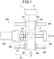
Fig. 1 is a diagram illustrating a configuration of a workpiece feeding apparatus and an operating-status diagnostic apparatus according to a first embodiment; -
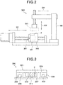
Fig. 2 is a diagram of the workpiece feeding apparatus viewed in a direction of an arrow II illustrated inFig. 1 ; -
Fig. 3 is a diagram of the workpiece feeding apparatus viewed in a direction of an arrow III illustrated inFig. 1 ; -
Fig. 4 is a cross-sectional view of a sensor unit illustrated inFig. 1 ; -
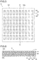
Fig. 5 is a plan view of a heat flux sensor illustrated inFig. 4 ; -
Fig. 6 is a cross-sectional view of the heat flux sensor taken along a line VI-VI illustrated inFig. 5 ; -
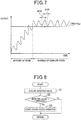
Fig. 7 is a diagram illustrating output waveforms of the sensor unit during a period in a warming-up state and during a period in a warming-up complete state; -
Fig. 8 is a flowchart illustrating operation control for the workpiece feeding apparatus according to the first embodiment; -
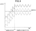
Fig. 9 is a diagram illustrating output waveforms of a heat flux sensor during a period when an environmental temperature is high and during a period when the environmental temperature is low, in a variation of the first embodiment in which one heat flux sensor is used; -
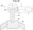
Fig. 10 is a diagram illustrating a configuration of an automatic cutting machine and an operating-status diagnostic apparatus according to a second embodiment; -
Fig. 11 is a cross-sectional view of a sensor unit according to a third embodiment; and -
Fig. 12 is a cross-sectional view of a sensor unit according to a fourth embodiment. - Embodiments of the present invention will be described below based on the figures. In descriptions of the embodiments, the same or equivalent components are designated by the same reference numerals.
- As illustrated in
Fig. 1 ,Fig. 2, and Fig. 3 , an operating-statusdiagnostic apparatus 1 according to the present embodiment diagnoses a warming-up complete status of aworkpiece feeding apparatus 300. Theworkpiece feeding apparatus 300 is installed in a production facility where a workpiece W1, which corresponds to a machining object, is machined. - As illustrated in
Fig. 2 , theworkpiece feeding apparatus 300 includes a linear movement mechanism M1 with aball screw 301, and a robot M2. Theworkpiece feeding apparatus 300 transfers the workpiece W1 using the linear movement mechanism M1 and the robot M2. The linear movement mechanism M1 transfers the workpiece W1 in a direction D1. The robot M2 transfers the workpiece W1 in a direction D2, a direction D3, and the like. - The robot M2 transfers the workpiece W1 to a
pedestal 304 of the linear movement mechanism M1. The robot M2 mounts the workpiece W1 on thepedestal 304. The linear movement mechanism M1 transfers the mounted workpiece W1. - As illustrated in
Fig. 1 andFig. 3 , the linear movement mechanism M1 includes aball screw 301,support members 302, amotor 303, thepedestal 304,rails 305, andguide blocks 306. InFig. 3 , thesupport members 302 are omitted for easier understanding. - The
ball screw 301 is a component of theworkpiece feeding apparatus 300. Theball screw 301 is a mechanical component which converts a rotary motion into a linear motion. Theball screw 301 has ascrew shaft 311, anut 312, andballs 313.Balls 313 are arranged between thescrew shaft 311 and thenut 312. Rotation of thescrew shaft 311 allows thenut 312 to move linearly. Each of thesupport members 302 supports a corresponding one of axially opposite ends of thescrew shaft 311. Themotor 303 is a power source which rotates thescrew shaft 311. - The
pedestal 304 is a component on which the workpiece W1 is mounted. Thepedestal 304 appears, in plan view, as a rectangle having a longitudinal direction orthogonal to the axial direction of the screw shaft 311 (that is, an up-down direction inFig. 1 ). A longitudinally approximately central portion of thepedestal 304 is coupled to thenut 312. Longitudinally opposite ends of thepedestal 304 are coupled to therespective guide blocks 306. - The
rails 305 are linear members. The tworails 305 are used and fixed to abase plate 307 as illustrated inFig. 3 . Theguide blocks 306 are engaged with the respective rails. Theguide blocks 306 serve as guide members which move along therespective rails 305. - As illustrated in
Fig. 1 , thediagnostic apparatus 1 includes asensor unit 2 and acontrol apparatus 3. - The
sensor unit 2 detects heat fluxes flowing outward from theball screw 301. Thesensor unit 2 outputs a sensor signal corresponding to heat fluxes flowing outward from theball screw 301 to thecontrol apparatus 3. Thesensor unit 2 is attached to a surface of thenut 312. Details of a structure of thesensor unit 2 will be described below. - The
sensor unit 2 is connected to an input side of thecontrol apparatus 3. Thecontrol apparatus 3 diagnoses an operating status of theball screw 301. In this diagnosis, whether or not the operating status of theball screw 301 indicates that theball screw 301 is in a warming-up complete state is determined based on a detection result from thesensor unit 2. Therefore, thecontrol apparatus 3 constitutes a control unit which determines, based on the detection result from theheat flux sensor 10, whether or not the operating status of a facility indicates that a component of the facility is in the warming-up complete state, where the warming-up of the component is completed. - The
motor 303, which serves as driving equipment for theworkpiece feeding apparatus 300, and the robot M2 are connected to an output side of thecontrol apparatus 3. Thecontrol apparatus 3 controls operation of theworkpiece feeding apparatus 300 based on the diagnosis result. Thecontrol apparatus 3 is configured to have a microcomputer and a storage apparatus. - Now, the structure of the
sensor unit 2 will be described. As illustrated inFig. 4 , thesensor unit 2 includes twoheat flux sensors 10, athermal buffer 11, and aheat sink 12. The twoheat flux sensors 10, thethermal buffer 11, and theheat sink 12 are all shaped like flat plates. - The two
heat flux sensors 10 have the same internal structure. One of the twoheat flux sensors 10 is a firstheat flux sensor 10a. Another one of the twoheat flux sensors 10 is a secondheat flux sensor 10b. - The first
heat flux sensor 10a is arranged in contact with an outer surface of thenut 312. The secondheat flux sensor 10b is arranged on a side far from thenut 312 with respect to the firstheat flux sensor 10a. Thethermal buffer 11 is arranged between the firstheat flux sensor 10a and the secondheat flux sensor 10b. Theheat sink 12 is arranged on the side far from thenut 312 with respect to the secondheat flux sensor 10b. That is, in thesensor unit 2, the firstheat flux sensor 10a, thethermal buffer 11, the secondheat flux sensor 10b, and theheat sink 12 are arranged in this order from the side close to thenut 312 toward the side far from thenut 312. - The first
heat flux sensor 10a outputs a first sensor signal corresponding to a heat flux passing through the firstheat flux sensor 10a from thenut 312 side thereof toward thethermal buffer 11 side thereof. The secondheat flux sensor 10b outputs a second sensor signal corresponding to a heat flux passing through the secondheat flux sensor 10b from thethermal buffer 11 side thereof toward the side opposite to thethermal buffer 11 side. The firstheat flux sensor 10a and the secondheat flux sensor 10b appears, in plan view, as rectangles which are the same in shape and size. - The
thermal buffer 11 has a predetermined heat capacity. Thethermal buffer 11 is formed of a metal material or a resin material. Thethermal buffer 11 has a material and a thickness set to provide a heat capacity which allows detection of changes in heat fluxes dissipated outward from thenut 312 as described below. Thethermal buffer 11 has a planar shape that is the same as the planar shape of the firstheat flux sensor 10a in form and size. Thethermal buffer 11 may have a planar shape that is different from the planar shape of the firstheat flux sensor 10a in form and size. - The
heat sink 12 has a predetermined heat capacity. Theheat sink 12 is formed of a metal material or a resin material. Theheat sink 12 has a material and a thickness set to provide a larger heat capacity than thethermal buffer 11. Theheat sink 12 is configured to have a larger planar shape than the firstheat flux sensor 10a, thethermal buffer 11, and the secondheat flux sensor 10b. Theheat sink 12 is fixed to thenut 312 with the firstheat flux sensor 10a, thethermal buffer 11, and the secondheat flux sensor 10b all sandwiched between theheat sink 12 and thenut 312. Specifically, threaded holes are formed in an outer circumferential portion of theheat sink 12. Theheat sink 12 is fixed to thenut 312 byscrews 13 inserted into the threaded holes.Spacers 14 are arranged between thenut 312 and theheat sink 12. Thescrews 13 penetrate therespective spacers 14. - As illustrated in
Fig. 5 and Fig. 6 , each of theheat flux sensors 10 includes an insulatingsubstrate 100, a frontsurface protecting member 110, and a backsurface protecting member 120, which are integrated together, and first and secondthermoelectric members integrated components Fig. 5 , thesurface protecting member 110 is omitted. The insulatingmaterial 100, the frontsurface protecting member 110, and the backsurface protecting member 120 are formed like films and constituted of a flexible resin material such as a thermoplastic resin. The insulatingsubstrate 100 has a plurality of first viaholes 101 and a plurality of second viaholes 102 formed therein in such a manner as to penetrate the insulatingsubstrate 100 in a thickness direction thereof. Firstthermoelectric members 130 and secondthermoelectric members 140, formed of different thermoelectric materials such as metals or semiconductors, are embedded in the first and second viaholes surface conductor pattern 111, arranged on afront surface 100a of the insulatingsubstrate 100, constitutes a one-side connection portion between each of the firstthermoelectric members 130 and the corresponding secondthermoelectric member 140. A backsurface conductor pattern 121, arranged on aback surface 100b of the insulatingsubstrate 100, constitutes an other-side connection portion between each of the firstthermoelectric members 130 and the corresponding secondthermoelectric member 140. - When heat fluxes pass through the
heat flux sensor 10 in a thickness direction thereof, a temperature difference occurs between the set of the one-side connection portions and the set of the other-side connection portions of the first and secondthermoelectric members thermoelectric members heat flux sensor 10 outputs the thermoelectromotive force, specifically, a voltage, as a sensor signal. - In the present embodiment, the first
heat flux sensor 10a and the secondheat flux sensor 10b are configured to output sensor signals with the same absolute value when heat fluxes passing through the respective heat flux sensors are of the same magnitude. - Furthermore, as illustrated in
Fig. 4 , the firstheat flux sensor 10a and the secondheat flux sensor 10b, connected together in series, are electrically connected to thecontrol apparatus 3. The firstheat flux sensor 10a and the secondheat flux sensor 10b are arranged such that, when heat fluxes from thenut 312 pass through the firstheat flux sensor 10a and the secondheat flux sensor 10b in this order, theheat flux sensors - Specifically, the first and second
heat flux sensors surface protecting members 110 thereof lie opposite to each other. Although not illustrated in the drawings, the frontsurface conductor patterns 111 of the first and secondheat flux sensors external wiring 151. The backsurface conductor patterns 121 of the first and secondheat flux sensors control apparatus 3 viaexternal wiring 152. Consequently, if a heat flux passes through the firstheat flux sensor 10a from the backsurface protecting member 120 side toward the frontsurface protecting member 110 side, then the heat flux passes through the secondheat flux sensor 10b from the frontsurface protecting member 110 side toward the backsurface protecting member 120 side, thus resulting in opposite polarities of the first and second sensor signals outputted from the first and secondheat flux sensors - In the present embodiment, each of the first and second
heat flux sensors surface protecting member 120 side toward the frontsurface protecting member 110 side. Thus, when heat fluxes flow from thenut 312 side toward theheat sink 12 side, the firstheat flux sensor 10a outputs a positive sensor signal, whereas the secondheat flux sensor 10b outputs a negative sensor signal. - The
sensor unit 2 outputs a sensor signal that is a combination of the first sensor signal and the second sensor signal to thecontrol apparatus 3. At this time, when a significant difference is present between the heat fluxes passing through the first and secondheat flux sensors sensor unit 2. This corresponds to, for example, a case where the amount of heat fluxes dissipated from a target has increased rapidly. On the other hand, when only an insignificant difference is present between the heat fluxes passing through the first and secondheat flux sensors sensor unit 2. This corresponds to, for example, a case where the amount of heat fluxes dissipated from the target has decreased or a predetermined amount of time has elapsed with a constant amount of heat fluxes dissipated from the target. - Now, the operation control of the
workpiece feeding apparatus 300 and the diagnosis of operating status of theball screw 301, which are performed by thecontrol apparatus 3, will be described. - First, the operation control of the
workpiece feeding apparatus 300 will be described. Thecontrol apparatus 3 performs a warming-up operation when the operation of theworkpiece feeding apparatus 300 is started. The warming-up operation is intended to raise the temperature of theball screw 301 from immediately after the start of the operation of theworkpiece feeding apparatus 300. In the warming-up operation, the linear movement mechanism M1 is operated with no workpiece W1 mounted thereon. In the warming-up operation, themotor 303 of the linear movement mechanism M1 is driven with the robot M2 being not driven. - The
control apparatus 3 performs a steady-state operation after the warming-up of theball screw 301 is completed. The steady-state operation is an operation performed with theball screw 301 stabilized. In the steady-state operation, the workpiece W1, mounted on thepedestal 304, is transferred. In the steady-state operation, themotor 303 for the robot M2 and the linear movement mechanism M1 is driven. - The reason why the warming-up operation is performed is as described below. During a certain period from immediately after the start of operation of the
workpiece feeding apparatus 300, frictional heat generated by theballs 312 inside thenut 312 is not dissipated but is accumulated in thenut 312. Consequently, the temperature of theball screw 301 rises. The rise in the temperature of theball screw 301 causes theball screw 301 to be thermally expanded. When the linear movement mechanism M1 is driven with theball screw 301 continuously thermally expanded, thepedestal 304 is stopped at a less accurate stop position. As a result, the workpiece W1 is inappropriately transferred. Moreover, the workpiece W1 is inappropriately machined. - More specifically, the moving distance of the
nut 312 depends on the rotation speed of thescrew shaft 311. For transfer of the workpiece W1, the rotation speed of thescrew shaft 311 is set to allow thepedestal 304 to stop at a predetermined position. However, when thescrew shaft 311 or thenut 312 is thermally expanded in the axial direction, the moving distance of thenut 312 varies even with the rotation speed of thescrew shaft 311 remaining the same. Thus, the stop position of thepedestal 304 varies. If the workpiece W1 is machined at a position to which the workpiece W1 has been transferred, the workpiece W1 is precluded from being machined when the stop position is different from the predetermined position. - Thus, the warming-up operation is performed until the
ball screw 301 is stabilized. Once the warming-up is completed, the operation is switched to the steady-state operation. Consequently, the workpiece W1 is restrained from being inappropriately transferred. - Next, heat fluxes passing through the
sensor unit 2 and the sensor signal output from thesensor unit 2 will be described. - The linear movement mechanism M1 repeats operation cycles each including operation and stoppage of the
ball screw 301. During operation of theball screw 301, the frictional heat generated by theballs 313 is dissipated from thenut 312, thus increasing an output value of thesensor unit 2. During stoppage of theball screw 301, no frictional heat is generated, thus reducing the output value of thesensor unit 2. Consequently, the output value of thesensor unit 2 is increased or reduced depending on the operation cycle both during a warming-up state where theball screw 301 is being warmed up and during a warming-up complete state where the warming-up is completed. - Immediately after the start of operation of the linear movement mechanism M1, when the
nut 312 has a low temperature, the frictional heat is accumulated in thenut 312. The temperature inside thenut 312 rises earlier than the temperature outside thenut 312. Thus, in this state, a smaller amount of heat is dissipated outward from thenut 312 than in the warming-up complete state. When heat is accumulated throughout thenut 312 to raise the temperature thereof, an increased amount of heat is dissipated outward from thenut 312. Thus, in the warming-up state, thesensor unit 2 has a waveform rising over time as illustrated inFig. 7 . - On the other hand, when the
ball screw 301 is in the warming-up complete state, the heat accumulation in thenut 312 has ended. The amount of heat resulting from the friction of the balls is equal to the amount of heat dissipated outward from thenut 312. Thus, during the warming-up complete state, thesensor unit 2 has an output waveform indicative of an output value which is larger than the output value during the warming-up state and which increases and decreases by an approximately constant magnitude as illustrated inFig. 7 . - Stoppage of the
ball screw 301 causes the heat accumulated in thenut 312 to be dissipated. However, theball screw 301 is operated during the heat dissipation. That is, theball screw 301 is operated in such operation cycles as allowing a certain amount of heat to be accumulated in thenut 312. Thus, thesensor unit 2 has a larger output value in the warming-up complete state than in the warming-up state in spite of the provision of the stoppage period for theball screw 301. - As described above, the output value from the
sensor unit 2 varies between the warming-up state and the warming-up complete state. Thus, a threshold is preset which is used to determine whether or not theball screw 301 is in the warming-up complete state, to allow the output value of thesensor unit 2 to be compared with the threshold. This enables determination of whether or not theball screw 301 is in the warming-up complete state. - Thus, in switching control for switching from the warming-up operation to the steady-state operation of the
workpiece feeding apparatus 300, thecontrol apparatus 3 diagnoses the operating status of theball screw 301 based on a detection result from thesensor unit 2 as illustrated inFig. 8 . The switching control is performed when the warming-up operation of theworkpiece feeding apparatus 300 is started. Steps illustrated inFig. 8 constitute a function implementing unit that implements various functions. - Specifically, the
control apparatus 3 acquires a detected value from thesensor unit 2. Here, the output value (Specifically, the voltage value) of thesensor unit 2 is acquired. Instead of using the output value of thesensor unit 2 without any change, it is also preferable to acquire a corrected value corresponding to the corrected output value, as the detected value. - Subsequently, in step S2, the
control apparatus 3 compares the detected value with the threshold pre-stored in the storage apparatus to determine whether or not the detected value is larger than the threshold. At this time, in step S1, thecontrol apparatus 3 acquires a plurality of detected values for different elapsed times from the start of the warming-up operation. In step S2, thecontrol apparatus 3 preferably determines whether or not all of the plurality of detected values are larger than the threshold. - In step S2, if the detected value is smaller than the threshold, the
control apparatus 3 makes a negative determination to end the control processing illustrated in the flowchart inFig. 8 . Thecontrol apparatus 3 then executes step S1 again. - On the other hand, if the detected value is larger than the threshold, the
control apparatus 3 makes an affirmative determination to proceed to step S3. In step S3, thecontrol apparatus 3 switches the operating status of theworkpiece feeding apparatus 300 from the warming-up operation to the steady-state operation. Consequently, the workpiece W1 is transferred by the linear movement mechanism M1 and the robot M2. Then, machining of the workpiece W1 is started. - As described above, the
diagnostic apparatus 1 of the present embodiment can appropriately determine whether or not the operating status of theball screw 301 indicates that theball screw 301 is in a warming-up complete state. - Furthermore, in the
diagnostic apparatus 1 of the present embodiment, thesensor unit 2 includes thethermal buffer 11 between the firstheat flux sensor 10a and the secondheat flux sensor 10b. Thecontrol apparatus 3 determines whether or not theball screw 301 is in the warming-up complete state based on the first sensor signal output by the firstheat flux sensor 10a and the second sensor signal output by the secondheat flux sensor 10b. - The
thermal buffer 11 accumulates and dissipates heat. Thus, when the heat fluxes dissipated from thenut 312 change, the heat flux passing through the secondheat flux sensor 10b changes later and more slowly than the heat flux passing through the firstheat flux sensor 10a does. Therefore, a difference between the first sensor signal and the second sensor signal allows a change in the heat fluxes dissipated from thenut 312 to be detected. - Alternatively, instead of the
sensor unit 2 of the present embodiment, the singleheat flux sensor 10 may exclusively be used to detect the heat fluxes dissipated from thenut 312. - However, in this case, when the environmental temperature around the
workpiece feeding apparatus 300 changes, the heat fluxes passing through theheat flux sensor 10 also changes under the effect of the environmental temperature. Specifically, even with the same amount of heat generated inside thenut 312, the heat fluxes passing through theheat flux sensor 10 have a larger magnitude when the environmental temperature is low than when the environmental temperature is high. Even with the same amount of heat generated inside thenut 312, the heat fluxes passing through theheat flux sensor 10 have a smaller magnitude when the environmental temperature is high than when the environmental temperature is low. - Thus, as illustrated by a solid line in
Fig. 9 , when the environmental temperature is lower than that illustrated by a wavy line inFig. 9 , the output value of thesensor unit 2 may exceed the threshold even if theball screw 301 is in the warming-up state. In this case, thecontrol apparatus 3 erroneously determines that theball screw 301 is in the warming-up complete state though theball screw 301 is actually in the warming-up state. Furthermore, as illustrated by an alternate long and short dash line inFig. 9 , when the environmental temperature is higher than that illustrated by a dashed line inFig. 9 , the output value of thesensor unit 2 may not exceed the threshold even if theball screw 301 is in the warming-up complete state. In this case, thecontrol apparatus 3 erroneously determines that theball screw 301 is in the warming-up state though theball screw 301 is actually in the warming-up complete state. - In contrast, the first
heat flux sensor 10a and the secondheat flux sensor 10b of thesensor unit 2 of the present embodiment are arranged on the opposite sides of thethermal buffer 11. Therefore, the firstheat flux sensor 10a and the secondheat flux sensor 10b are arranged relatively close to each other. Furthermore, the environmental temperature around thesensor unit 2 typically varies slowly over a long period of one day. Thus, even though thethermal buffer 11 is arranged between the firstheat flux sensor 10a and the secondheat flux sensor 10b, the firstheat flux sensor 10a and the secondheat flux sensor 10b are subjected to the same or substantially the same effect of the environmental temperature. Each of the firstheat flux sensor 10a and the secondheat flux sensor 10b outputs a sensor signal corresponding to the heat flux subjected to the same effect of the environmental temperature. Outputs from the firstheat flux sensor 10a and the secondheat flux sensor 10b have the same absolute value for the same magnitude of the heat flux. Therefore, the use of the sum of the outputs from the firstheat flux sensor 10a and the secondheat flux sensor 10b allows elimination (that is, cancellation) of the effect of the environmental temperature on the detection result from thesensor unit 2. - Thus, the output waveform of the
sensor unit 2 in the warming-up complete state is free from the effect of the environmental temperature as illustrated inFig. 7 . This allows avoidance of erroneous determination caused by a variation in the environmental temperature during a single day. - Therefore, the
diagnostic apparatus 1 of the present embodiment can accurately diagnose the warming-up complete status. The outputs from the firstheat flux sensor 10a and the secondheat flux sensor 10b do not necessarily have the same absolute value for the same magnitude of the heat flux. The outputs may have any absolute values as long as the absolute values are close to each other. Even in this case, the use of the sum of the outputs from the firstheat flux sensor 10a and the secondheat flux sensor 10b enables a reduction in the effect of the environmental temperature on the detection result from thesensor unit 2. - Furthermore, in the
sensor unit 2 of the present embodiment, the firstheat flux sensor 10a and the secondheat flux sensor 10b output the first sensor signal and the second sensor signal, respectively, which have an opposite polarity relation, when a heat flux from thenut 312 passes through the firstheat flux sensor 10a and the secondheat flux sensor 10b in this order. The firstheat flux sensor 10a and the secondheat flux sensor 10b, connected together in series, are electrically connected to thecontrol apparatus 3. Consequently, a sensor signal corresponding to a combination of the first sensor signal and the second sensor signal can be outputted from thesensor unit 2 toward thecontrol apparatus 3. This allows omission of the calculation of the sum of the first sensor signal and the second sensor signal performed by thecontrol apparatus 3. That is, the calculation processing executed by thecontrol apparatus 3 can be simplified. - The
sensor unit 2 may be configured not to have theheat sink 12. However, if thesensor unit 2 does not have theheat sink 12, a front surface temperature of the secondheat flux sensor 10b instantaneously changes, for example, because the front surface of the secondheat flux sensor 10b is exposed to atmosphere. This affects the heat fluxes passing through thesensor unit 2. Thus, thesensor unit 2 has a reduced accuracy with which the heat fluxes are detected. - In contrast, the
sensor unit 2 of the present embodiment includes theheat sink 12 having a predetermined heat capacity. Consequently, even if the front surface temperature of thesensor unit 2 varies in a short period of time, a possible variation in the temperature of the secondheat flux sensor 10b can be suppressed from occurring by accumulation and dissipation of heat in and from theheat sink 12. Thus, the accuracy with which thesensor unit 2 detects the heat fluxes can be increased. - Furthermore, in the
sensor unit 2 of the present embodiment, theheat sink 12 is configured to have a larger heat capacity than thethermal buffer 11. Consequently, even when a large amount of heat is dissipated from thenut 312, the heat can be directed from thenut 312 toward theheat sink 12. Thus, heat can be prevented from being trapped inside thesensor unit 2. - As illustrated in
Fig. 10 , an operating-statusdiagnostic apparatus 1 according to the present embodiment diagnoses a warming-up complete status of anautomatic cutting machine 400. - The
automatic cutting machine 400 includes adrill 401, achuck unit 402 for the drill, and a chuck unit for a workpiece. Thedrill 401 is a cutting tool used for cutting. Thechuck unit 402 for the drill is a holding unit which holds thedrill 401. Thechuck unit 403 for the workpiece is a holding unit which holds a workpiece W2, corresponding to a machining object. Theautomatic cutting machine 400 repeats machining and stoppage to machine a plurality of workpieces W2 one by one in this order. During machining, friction between thedrill 401 and the workpiece W2 causes thedrill 401 to generate heat. The heat generated by thedrill 401 is dissipated outward from thechuck unit 402 of the drill. - The
diagnostic apparatus 1 includes thesensor unit 2 and thecontrol apparatus 3. - The
sensor unit 2 is attached to a front surface of thechuck unit 402 for the drill. Thesensor unit 2 detects heat fluxes flowing outward from thedrill 401 via thechuck unit 402 for the drill. Thesensor unit 2 outputs a sensor signal corresponding to heat fluxes flowing outward from thedrill 401 via thechuck unit 402 for the drill to thecontrol apparatus 3. A configuration of thesensor unit 2 is the same as the configuration of thesensor unit 2 of the first embodiment. - The
control apparatus 3 performs operation control for theautomatic cutting machine 400 and diagnosis of the operating status of thedrill 401. In the operation control for theautomatic cutting machine 400, thecontrol apparatus 3 performs a warming-up operation on thedrill 401 when operation of theautomatic cutting machine 400 is started. The warming-up operation is an operation for machining a workpiece for warming-up instead of the workpiece W2, intended for machining. Thecontrol apparatus 3 performs a steady-state operation after the warming-up operation for thedrill 401. The steady-state operation is an operation for machining the workpiece W2, intended for machining. - During a certain period from immediately after the start of operation of the
automatic cutting machine 400, thedrill 401 generates heat to raise the temperature of thedrill 401. The rise in the temperature of thedrill 401 causes thedrill 401 to be thermally expanded. When the workpiece W2 is machined with thedrill 401 continuously thermally expanding, machining accuracy decreases. Thus, the warming-up operation is performed until thedrill 401 is stabilized. Once the warming-up is completed, thecontrol apparatus 3 switches from the warming-up operation to the steady-state operation. - To switch from the warming-up operation to the steady-state operation, the
control apparatus 3 diagnoses the operating status of thedrill 401. Specifically, thecontrol apparatus 3 determines whether or not the operating status of thedrill 401 indicates that thedrill 401 is in a warming-up complete state based on a detection result from thesensor unit 2. - Output waveforms obtained when the
drill 401 is in the warming-up state and when thedrill 401 is in the warming-up complete state are similar to the waveforms described in the first embodiment and illustrated inFig. 7 . Thus, also in the present embodiment, a threshold used to determine whether or not thedrill 401 is in the warming-up complete state is pre-stored in thecontrol apparatus 3. Then, thecontrol apparatus 3 compares an output value of thesensor unit 2 with the threshold. Consequently, thecontrol apparatus 3 can determine whether or not thedrill 401 is in the warming-up complete state. - Furthermore, the
sensor unit 2 used for thediagnostic apparatus 1 has the same configuration as thesensor unit 2 of the first embodiment. Thus, thediagnostic apparatus 1 of the present embodiment produces effects similar to those of thediagnostic apparatus 1 of the first embodiment. - The first
heat flux sensor 10 may exclusively be used as thesensor unit 2 used for thediagnostic apparatus 1. - The present embodiment corresponds to the first embodiment with the configuration of the
sensor unit 2 being changed. The remaining part of the configuration of adiagnostic apparatus 1 of the present embodiment is the same as the corresponding part in the first embodiment. - As illustrated in
Fig. 11 , asensor unit 2 of the present embodiment has a flat-plate-like heat receiver 16. Theheat receiver 16 is arranged closer to anut 312 than a firstheat flux sensor 10a is. Therefore, theheat receiver 16 is arranged between thenut 312 and the firstheat flux sensor 10a. - Like the
thermal buffer 11 and theheat sink 12, theheat receiver 16 has a predetermined heat capacity. Theheat receiver 16 is formed of a metal material or a resin material. Theheat receiver 16 has a material and a thickness set to provide a smaller heat capacity than thethermal buffer 11 and theheat sink 12. Theheat receiver 16 has a planar shape which is the same as the planar shape of the firstheat flux sensor 10a in form and size. The planar shape of theheat receiver 16 may be different from the planar shape of the firstheat flux sensor 10a in form and size. - In the
sensor unit 2 of the present embodiment, a possible short-time change in heat fluxes such as noise which is not intended to be detected can be restrained from affecting the first and secondheat flux sensors heat receiver 16. - Furthermore, in the
sensor unit 2 of the present embodiment, a small heat capacity is set for theheat receiver 16. Thus, thesensor unit 2 of the present embodiment can detect changes in heat fluxes resulting from operation and stoppage of theball screw 301 of which changes are intended to be detected. That is, in thesensor unit 2 of the present embodiment, the heat capacity of theheat receiver 16 is set to a magnitude at which thesensor unit 2 can detect changes in heat fluxes resulting from operation and stoppage of theball screw 301. - Therefore, the
diagnostic apparatus 1 of the present embodiment can accurately determine whether or not theball screw 301 is in the warming-up complete state. Also in the second embodiment, thesensor unit 2 may be configured to have theheat receiver 16. Then, the second embodiment produces effects similar to those of the present embodiment. - The present embodiment corresponds to the first embodiment with the configuration of the
sensor unit 2 being changed. The remaining part of the configuration of adiagnostic apparatus 1 of the present embodiment is the same as the corresponding part in the first embodiment. - As illustrated in
Fig. 12 , in thesensor unit 2 of the present embodiment, the first and secondheat flux sensors bent shape portion 10c having a bent shape. Like the first and secondheat flux sensor bent shape portion 10c is structured such that the insulatingsubstrate 100, the frontsurface protecting member 110, and the backsurface protecting member 120 are laid on top of one another. Consequently, in thesensor unit 2 of the present embodiment, the first and secondheat flux sensors - In other words, the
sensor unit 2 of the present embodiment is structured such that the singleheat flux sensor 10 is bent in such a manner as to enclose thethermal buffer 11. In theheat flux sensor 10, each of the insulatingsubstrate 100, the frontsurface protecting member 110, and the backsurface protecting member 120 is formed of a flexible resin material as described above. Thus, theheat flux sensor 10 can be easily bent. This results in implementation of the configuration where thethermal buffer 11 is arranged between the firstheat flux sensor 10a and the secondheat flux sensor 10b. - For the first and second
heat flux sensors surface conductor patterns 121 thereof are connected together. The first and secondheat flux sensors heat flux sensor 10 instead of theexternal wiring 151. Alternatively, for the first and secondheat flux sensors - Consequently, the first and second
heat flux sensors heat flux sensor 10, allowing omission of theexternal wiring 151 used for connecting the firstheat flux sensor 10a and the secondheat flux sensor 10b. Therefore, the number of components to be needed can be reduced. - The present invention is not limited to the above-described embodiments, and appropriate modifications may be made to the embodiments within the scope recited in the claims.
- (1) The
diagnostic apparatus 1 of the first embodiment has theworkpiece feeding apparatus 300 as a diagnosis target. Thediagnostic apparatus 1 of the second embodiment has theautomatic cutting machine 400 as a diagnosis target. The diagnosis target of thediagnostic apparatus 1 is not limited to these apparatuses. Thediagnostic apparatus 1 may have, as a diagnosis target, another facility in which a warming-up operation is performed. - (2) In the first embodiment, to determine whether or not the diagnosis target is in the warming-up complete state, the
control apparatus 3 determines in step S2 whether or not the absolute value of the detected value is larger than the threshold. However, thecontrol apparatus 3 may make another determination. As described in the first embodiment, thesensor unit 2 provides an output waveform exhibiting an increase or a decrease by an approximately constant magnitude in the warming-up complete state. Thus, thecontrol apparatus 3 may calculate a range of fluctuation corresponding to a difference between the minimum value and the maximum value of the detected value during a predetermined period and determine whether or not the calculated range of fluctuation is smaller than a predetermined range. - (3) In the first embodiment, the
single control apparatus 3 performs diagnosis of the warming-up complete status as a part of the switching control for switching from the warming-up operation to the steady-state operation. However, one of two separate control apparatuses may perform the switching control, and the other control apparatus may perform the diagnosis. In this case, the control apparatus performing the diagnosis constitutes the control unit of the operating-status diagnostic apparatus. - (4) In the first embodiment, the
control apparatus 3 switches from the warming-up operation to the steady state in step S3, in a case of determining that the diagnosis target is in the warming-up complete state because the detected value has exceeded the threshold. In contrast, if the warming-up operation is manually switched to the steady state, the warming-up complete may be displayed on a display apparatus in step S3. - (5) In the
sensor unit 2 in the first to third embodiments, the firstheat flux sensor 10a and the secondheat flux sensor 10b, connected together in series, are electrically connected to thecontrol apparatus 3. However, the firstheat flux sensor 10a and the secondheat flux sensor 10b may be connected in parallel with thecontrol apparatus 3. - (6) In the
sensor unit 2 in the first to third embodiments, the firstheat flux sensor 10a and the secondheat flux sensor 10b are arranged so as to output the first sensor signal and the second sensor signal having the opposite polarity relation. However, the arrangement of the firstheat flux sensor 10a and the secondheat flux sensor 10b is not limited thereto. The firstheat flux sensor 10a and the secondheat flux sensor 10b may be arranged so as to output the first sensor signal and the second sensor signal having the same polarity. In this case, the firstheat flux sensor 10a and the secondheat flux sensor 10b are connected in parallel with thecontrol apparatus 3. Furthermore, in the diagnosis of the operating status, thecontrol apparatus 3 calculates the difference between the first sensor signal and the second sensor signal. Consequently, the diagnosis can be performed as is the case with the first and second embodiments. - (7) In the
sensor unit 2 in the first to third embodiments, the insulatingsubstrate 100, the frontsurface protecting member 110, and the backsurface protecting member 120 of theheat flux sensor 10 may be formed of a flexible insulating material other than the resin material. Moreover, the insulatingsubstrate 100, the frontsurface protecting member 110, and the backsurface protecting member 120 may be formed of an inflexible insulating material. Alternatively, theheat flux sensor 10 may be structured not to have the frontsurface protecting member 110 or the backsurface protecting member 120. Furthermore, theheat flux sensor 10 may have a configuration different from the above-described one. - (8) In the
sensor unit 2 of the fourth embodiment, the insulatingsubstrate 100, the frontsurface protecting member 110, and the backsurface protecting member 120 of theheat flux sensor 10 may be formed of a flexible insulating material other than the resin material. Alternatively, theheat flux sensor 10 may be structured not to have the frontsurface protecting member 110 or the backsurface protecting member 120. In this case, the firstheat flux sensor 10a and the secondheat flux sensor 10b are connected together via thebent shape portion 10c constituted of the insulatingsubstrate 100. In short, thebent shape portion 10c may be configured to contain the same insulating material as that of the insulatingsubstrate 100. - (9) The
sensor unit 2 of each of the above-described embodiments includes the twoheat flux sensors 10, thethermal buffer 11, and theheat sink 12. However, theheat sink 12 may be omitted. In this case, thesensor unit 2 is fixed using another fixing member or an adhesive. - (10) In each of the above-described embodiments, the voltage is used as the sensor signal from the
sensor unit 2. However, an electric current may be used as the sensor signal from thesensor unit 2. - (11) The above-described embodiments are not irrelevant to one another but may be appropriately combined together unless the combination is obviously impossible. Furthermore, the elements constituting each of the above-described embodiments are of course not necessarily essential unless otherwise specified and unless the elements are obviously essential in principle.
- According to a first aspect disclosed by a part or all of each of the above-described embodiments, an operating-status diagnostic apparatus includes a sensor unit and a control unit. The sensor unit detects heat fluxes flowing outward from a component of a facility. The control unit determines whether or not an operating status of the facility indicates that the component is in a warming-up complete state where warming-up of the component is completed.
- According to a second aspect, the sensor unit has a first heat flux sensor, a second heat flux sensor, and a thermal buffer arranged between the first heat flux sensor and the second heat flux sensor. The first heat flux sensor outputs a first sensor signal corresponding to a heat flux passing through the first heat flux sensor. The second heat flux sensor outputs a second sensor signal corresponding to a heat flux passing through the second heat flux sensor. The control unit determines whether or not the component is in the warming-up complete state based on the first sensor signal and the second sensor signal.
- In the second aspect, the thermal buffer is arranged between the first heat flux sensor and the second heat flux sensor in the sensor unit. Thus, when the heat fluxes dissipated from the component change, the heat flux passing through the second heat flux sensor changes later and more slowly than the heat flux passing through the first heat flux sensor does. Therefore, the change in the heat fluxes dissipated from the component can be detected based on the difference between the first sensor signal and the second sensor signal.
- The first heat flux sensor and the second heat flux sensor are arranged on the opposite sides of the thermal buffer and relatively close to each other. The environmental temperature, which is the temperature of an environment where the sensor unit is installed, typically varies slowly over a long period of time. Thus, the first heat flux sensor and the second heat flux sensor are subjected to the same or substantially the same effect of the environmental temperature. Each of the first heat flux sensor and the second heat flux sensor outputs a sensor signal corresponding to the heat flux subjected to the same or substantially the same effect of the environmental temperature. Therefore, the use of the sensor signals from both heat flux sensors enables elimination or reduction of the effect of the environmental temperature on the detection result from the sensor unit. Therefore, the diagnostic apparatus of the second aspect can accurately diagnose the warming-up complete status.
- Furthermore, according to a third aspect, the sensor unit has a heat sink arranged farther from the component than the second heat flux sensor is and having a predetermined heat capacity.
- Consequently, even if the surface temperature of the sensor unit varies in a short period of time, a possible variation in the temperature of the second heat flux sensor can be suppressed from occurring. Thus, the accuracy of the heat fluxes which the sensor unit detects can be improved.
- Furthermore, according to a fourth aspect, the heat sink is configured to have a larger heat capacity than the thermal buffer. Consequently, even when the component dissipates a large amount of heat, the heat can be passed from the component toward the heat sink. Thus, the heat can be prevented from being trapped inside the sensor unit.
- Furthermore, according to a fifth aspect, the sensor unit has a heat receiver arranged closer to the component than the first heat flux sensor is. The heat receiver is configured to have a smaller heat capacity than the thermal buffer.
- Consequently, a possible short-time change in heat fluxes such as noise which is not intended to be detected can be restrained from affecting the first and second heat flux sensors based on accumulation and dissipation of heat in and from the heat receiver. Furthermore, setting a reduced heat capacity for the heat receiver allows the sensor unit to detect a change in heat fluxes dissipated from the component which change is intended to be detected.
- Furthermore, according to a sixth aspect, in the sensor unit, the first heat flux sensor and second heat flux sensor are arranged such that the first sensor signal and the second sensor signal have opposite polarities when heat fluxes from the component pass through the first heat flux sensor and the second heat flux sensor in this order. The first heat flux sensor and the second heat flux sensor are electrically connected together in series.
- Consequently, the sensor unit can output a sensor signal corresponding to a combination of the first sensor signal and the second sensor signal. This enables elimination of the need for a calculation process for the sum of the first sensor signal and the second sensor signal.
- Furthermore, according to a seventh aspect, each of the first heat flux sensor and the second heat flux sensor is configured to have a flexible film-like insulating substrate, a plurality of first thermoelectric members, and a plurality of second thermoelectric members. The plurality of first thermoelectric members and the plurality of second thermoelectric members are alternately connected together in series. The first heat flux sensor and the second heat flux sensor are connected together via a bent shape portion configured to contain an insulating material.
- This eliminates the need for external wiring for connection between the first heat flux sensor and the second heat flux sensor.
-
- 1 ...
- Diagnostic apparatus for warming-up complete status
- 2 ...
- Sensor unit
- 3 ...
- Control apparatus
- 10a ...
- First heat flux sensor
- 10b ...
- Second heat flux sensor
- 11 ...
- Thermal buffer
- 12 ...
- Heat sink
- 16 ...
- Heat receiver
- The following aspects are incorporated in this application in order to preserve the complete disclosure of the parent application:
- 1. An operating-status diagnostic apparatus diagnosing an operating status of a facility, the apparatus comprising:
- a sensor unit (2) for detecting heat fluxes flowing outward from a component (301, 401) of the facility; and
- a control unit (3) for determining whether or not the operating status of the facility indicates that the component is in a warming-up complete state where warming-up of the component is completed based on a detection result of detection by the sensor unit.
- 2. The operating-status diagnostic apparatus according to
claim 1, wherein
the sensor unit has:- a first heat flux sensor (10a);
- a second heat flux sensor (10b) arranged farther from the component than the first heat flux sensor is; and
- a thermal buffer (11) arranged between the first heat flux sensor and the second heat flux sensor and having a predetermined heat capacity, wherein
- the first heat flux sensor outputs a first sensor signal corresponding to a heat flux passing through the first heat flux sensor from the component side toward the thermal buffer,
- the second heat flux sensor outputs a second sensor signal corresponding to a heat flux passing through the second heat flux sensor from the thermal buffer side toward a side opposite to the thermal buffer side, and
- the control unit determines whether or not the component is in the warming-up complete state based on the first sensor signal and the second sensor signal.
- 3. The operating-status diagnostic apparatus according to
claim 2, wherein
the sensor unit has a heat sink (12) arranged farther from the component than the second heat flux sensor is and has a predetermined heat capacity. - 4. The operating-status diagnostic apparatus according to
claim 3, wherein
the heat sink is configured to have a larger heat capacity than the thermal buffer. - 5. The operating-status diagnostic apparatus according to any one of
claims 2 to 4, wherein
the sensor unit has a heat receiver (16) arranged closer to the component than the first heat flux sensor is, and
the heat receiver is configured to have a smaller heat capacity than the thermal buffer. - 6. The operating-status diagnostic apparatus according to any one of
claims 2 to 5, wherein
the first heat flux sensor and the second heat flux sensor are arranged such that, when a heat flux from the component passes through the first heat flux sensor and the second heat flux sensor in this order, the first sensor signal and the second sensor signal have opposite polarities, and
the first heat flux sensor and the second heat flux sensor are electrically connected together in series. - 7. The operating-status diagnostic apparatus according to claim 6, wherein
each of the first heat flux sensor and the second heat flux sensor has:- an insulating substrate (100) formed at least of an insulating material and having flexibility,
- a plurality of first thermoelectric members (130) formed in the insulating substrate and formed of a thermoelectric material, and
- a plurality of second thermoelectric members (140) formed in the insulating substrate and formed of a thermoelectric material different from the thermoelectric material of the first thermoelectric members,
- the plurality of first thermoelectric members and the plurality of second thermoelectric members are alternately connected together in series, and
- the first heat flux sensor and the second heat flux sensor are connected together via a bent shape portion (10c) configured to include the insulating material.
Claims (6)
- A configuration of a facility and an operating-status diagnostic apparatus for diagnosing an operating status of the facility, wherein
the facility is a workpiece feeding apparatus (300) including a linear movement mechanism (M1) for transferring a workpiece (W1) and
the operating-status diagnostic apparatus is comprising:a sensor unit (2) for detecting heat fluxes flowing outward from a component (301) of the facility; anda control unit (3) for determining whether or not the operating status of the facility indicates that the component is in a warming-up complete state where warming-up of the component is completed based on a detection result of detection by the sensor unit (2),wherein the sensor unit (2) has:a first heat flux sensor (10a);a second heat flux sensor (10b) arranged farther from the component than the first heat flux sensor is; anda thermal buffer (11) arranged between the first heat flux sensor and the second heat flux sensor and having a predetermined heat capacity, whereinthe first heat flux sensor outputs a first sensor signal corresponding to a heat flux passing through the first heat flux sensor from the component side toward the thermal buffer,the second heat flux sensor outputs a second sensor signal corresponding to a heat flux passing through the second heat flux sensor from the thermal buffer side toward a side opposite to the thermal buffer side,characterized in thatthe control unit (3) is configured to perform a warming-up operation when the operation of the workpiece feeding apparatus 300 is started and to determine during the warming-up operation whether or not the component is in the warming-up complete state based on the first sensor signal and the second sensor signal and, upon determination of the warming-up complete state, to switch to a steady-state operation; andthe workpiece feeding apparatus (300) further includes a robot (M2) configured to transfer a workpiece (W1) to the linear movement mechanism (M1) upon determination of the warming-up complete state by the control unit (3). - The configuration according to claim 1, wherein
the sensor unit (2) has a heat sink (12) arranged farther from the component than the second heat flux sensor is and has a predetermined heat capacity. - 3. The configuration according to claim 2, wherein
the heat sink is configured to have a larger heat capacity than the thermal buffer. - 4. The configuration according to any one of claims 1 to 3, wherein
the sensor unit (2) has a heat receiver (16) arranged closer to the component than the first heat flux sensor is, and
the heat receiver is configured to have a smaller heat capacity than the thermal buffer. - The configuration according to any one of claims 1 to 4, wherein
the first heat flux sensor and the second heat flux sensor are arranged such that, when a heat flux from the component passes through the first heat flux sensor and the second heat flux sensor in this order, the first sensor signal and the second sensor signal have opposite polarities, and
the first heat flux sensor and the second heat flux sensor are electrically connected together in series. - The configuration according to claim 5, wherein
each of the first heat flux sensor and the second heat flux sensor has:an insulating substrate (100) formed at least of an insulating material and having flexibility,a plurality of first thermoelectric members (130) formed in the insulating substrate and formed of a thermoelectric material, anda plurality of second thermoelectric members (140) formed in the insulating substrate and formed of a thermoelectric material different from the thermoelectric material of the first thermoelectric members,the plurality of first thermoelectric members and the plurality of second thermoelectric members are alternately connected together in series, andthe first heat flux sensor and the second heat flux sensor are connected together via a bent shape portion (10c) configured to include the insulating material.
Applications Claiming Priority (3)
| Application Number | Priority Date | Filing Date | Title |
|---|---|---|---|
| JP2015222445A JP6358234B2 (en) | 2015-11-12 | 2015-11-12 | Operational diagnostic device |
| EP16864263.5A EP3376199A4 (en) | 2015-11-12 | 2016-11-09 | Operation state diagnostic device |
| PCT/JP2016/083248 WO2017082302A1 (en) | 2015-11-12 | 2016-11-09 | Operation state diagnostic device |
Related Parent Applications (1)
| Application Number | Title | Priority Date | Filing Date |
|---|---|---|---|
| EP16864263.5A Division EP3376199A4 (en) | 2015-11-12 | 2016-11-09 | Operation state diagnostic device |
Publications (1)
| Publication Number | Publication Date |
|---|---|
| EP3702751A1 true EP3702751A1 (en) | 2020-09-02 |
Family
ID=58695419
Family Applications (2)
| Application Number | Title | Priority Date | Filing Date |
|---|---|---|---|
| EP20170272.7A Withdrawn EP3702751A1 (en) | 2015-11-12 | 2016-11-09 | Operating-status diagnostic apparatus |
| EP16864263.5A Ceased EP3376199A4 (en) | 2015-11-12 | 2016-11-09 | Operation state diagnostic device |
Family Applications After (1)
| Application Number | Title | Priority Date | Filing Date |
|---|---|---|---|
| EP16864263.5A Ceased EP3376199A4 (en) | 2015-11-12 | 2016-11-09 | Operation state diagnostic device |
Country Status (7)
| Country | Link |
|---|---|
| US (1) | US10859447B2 (en) |
| EP (2) | EP3702751A1 (en) |
| JP (1) | JP6358234B2 (en) |
| KR (1) | KR102134003B1 (en) |
| CN (1) | CN108351276B (en) |
| TW (1) | TWI620355B (en) |
| WO (1) | WO2017082302A1 (en) |
Families Citing this family (4)
| Publication number | Priority date | Publication date | Assignee | Title |
|---|---|---|---|---|
| JP6358234B2 (en) * | 2015-11-12 | 2018-07-18 | 株式会社デンソー | Operational diagnostic device |
| JP6358233B2 (en) | 2015-11-12 | 2018-07-18 | 株式会社デンソー | Assembly diagnostic device |
| JP7053357B2 (en) * | 2018-04-19 | 2022-04-12 | 日本アビオニクス株式会社 | Ultrasonic bonding device |
| CN116481804B (en) * | 2022-01-14 | 2025-07-25 | 库卡机器人(广东)有限公司 | Test device |
Citations (4)
| Publication number | Priority date | Publication date | Assignee | Title |
|---|---|---|---|---|
| JPH05301144A (en) * | 1992-04-23 | 1993-11-16 | Suzuki Motor Corp | Machine tool warm-up device |
| DE102006016956A1 (en) * | 2006-04-11 | 2007-10-18 | Electrolux Home Products Corp. N.V. | Determination device for thermal values, has substrate, which is arranged or attachable within heat flux in equipment, two temperature sensors, which are attached on substrate |
| JP5376086B1 (en) | 2012-05-30 | 2013-12-25 | 株式会社デンソー | Method for manufacturing thermoelectric conversion device, method for manufacturing electronic component including thermoelectric conversion device |
| WO2014196294A1 (en) * | 2013-06-04 | 2014-12-11 | 株式会社デンソー | Vehicle abnormality determination device |
Family Cites Families (27)
| Publication number | Priority date | Publication date | Assignee | Title |
|---|---|---|---|---|
| US4274475A (en) * | 1979-06-04 | 1981-06-23 | Dieter Rall | Control apparatus for regulating building perimeter temperature change system |
| JPS60201224A (en) * | 1984-03-27 | 1985-10-11 | Kyushu Daigaku | Multilayered thin-film heat conduction gauge |
| JPS6156759A (en) * | 1984-08-27 | 1986-03-22 | Nippon Kokan Kk <Nkk> | Preheating method of vessel for molten metal |
| US4784212A (en) * | 1986-11-21 | 1988-11-15 | Transmet Engineering, Inc. | Building perimeter thermal energy control system |
| US4779994A (en) * | 1987-10-15 | 1988-10-25 | Virginia Polytechnic Institute And State University | Heat flux gage |
| JPH0478933A (en) * | 1990-07-20 | 1992-03-12 | Fujitsu Ltd | Program processing system by virtual processor |
| GB2280506A (en) * | 1993-07-29 | 1995-02-01 | Euratom | Thermostatic device |
| JPH08201188A (en) * | 1995-01-24 | 1996-08-09 | Mitsubishi Heavy Ind Ltd | Heat flux meter |
| US6392431B1 (en) * | 1996-10-23 | 2002-05-21 | Aetrium, Inc. | Flexibly suspended heat exchange head for a DUT |
| DE10142269A1 (en) * | 2001-08-29 | 2003-04-03 | Siemens Dematic Ag | Device for picking up and / or setting down, and method for detecting moving components |
| JP2008057670A (en) * | 2006-08-31 | 2008-03-13 | F C C:Kk | Heat generation amount estimation device for clutch |
| US8568021B2 (en) * | 2011-09-29 | 2013-10-29 | Schwank Ltd. | Apparatus and method for measuring heat flux from radiant heater |
| US9167228B2 (en) * | 2012-01-03 | 2015-10-20 | Lawrence Maxwell Monari | Instrumented sports paraphernalia system |
| US9377370B2 (en) | 2012-02-29 | 2016-06-28 | Solar Turbines Incorporated | Heat flux gauge with micro-scale temperature sensors |
| CH707390A2 (en) * | 2012-12-28 | 2014-06-30 | Greenteg Ag | Heat flux sensor. |
| JP5922265B2 (en) * | 2013-01-24 | 2016-05-24 | ジヤトコ株式会社 | Temperature estimation calculation device for friction engagement elements |
| EP2990878B1 (en) * | 2013-04-24 | 2017-09-06 | Kyocera Document Solutions Inc. | Fixing device and image formation device |
| JP5761302B2 (en) * | 2013-06-04 | 2015-08-12 | 株式会社デンソー | Comfortable temperature control device for vehicles |
| JP5942960B2 (en) * | 2013-06-04 | 2016-06-29 | 株式会社デンソー | Calorific value control device |
| US9350319B2 (en) * | 2014-02-24 | 2016-05-24 | Siemens Energy, Inc. | Self-powered sensing and transmitting device and method of fabricating the same |
| JP6303973B2 (en) * | 2014-10-20 | 2018-04-04 | 株式会社デンソー | Condition detection sensor |
| JP6451484B2 (en) * | 2015-05-11 | 2019-01-16 | 株式会社デンソー | Heat flux sensor manufacturing method and heat flow generator used therefor |
| JP2017067761A (en) * | 2015-10-01 | 2017-04-06 | 株式会社デンソー | Abnormal sign diagnosis device |
| JP6249009B2 (en) | 2015-11-12 | 2017-12-20 | 株式会社デンソー | Abnormality diagnosis device |
| JP6358233B2 (en) | 2015-11-12 | 2018-07-18 | 株式会社デンソー | Assembly diagnostic device |
| JP6358234B2 (en) * | 2015-11-12 | 2018-07-18 | 株式会社デンソー | Operational diagnostic device |
| JP6500825B2 (en) * | 2016-04-08 | 2019-04-17 | 株式会社デンソー | Monitoring device |
-
2015
- 2015-11-12 JP JP2015222445A patent/JP6358234B2/en active Active
-
2016
- 2016-11-09 WO PCT/JP2016/083248 patent/WO2017082302A1/en not_active Ceased
- 2016-11-09 EP EP20170272.7A patent/EP3702751A1/en not_active Withdrawn
- 2016-11-09 EP EP16864263.5A patent/EP3376199A4/en not_active Ceased
- 2016-11-09 KR KR1020187013460A patent/KR102134003B1/en active Active
- 2016-11-09 US US15/775,744 patent/US10859447B2/en active Active
- 2016-11-09 CN CN201680065787.7A patent/CN108351276B/en not_active Expired - Fee Related
- 2016-11-10 TW TW105136654A patent/TWI620355B/en not_active IP Right Cessation
Patent Citations (4)
| Publication number | Priority date | Publication date | Assignee | Title |
|---|---|---|---|---|
| JPH05301144A (en) * | 1992-04-23 | 1993-11-16 | Suzuki Motor Corp | Machine tool warm-up device |
| DE102006016956A1 (en) * | 2006-04-11 | 2007-10-18 | Electrolux Home Products Corp. N.V. | Determination device for thermal values, has substrate, which is arranged or attachable within heat flux in equipment, two temperature sensors, which are attached on substrate |
| JP5376086B1 (en) | 2012-05-30 | 2013-12-25 | 株式会社デンソー | Method for manufacturing thermoelectric conversion device, method for manufacturing electronic component including thermoelectric conversion device |
| WO2014196294A1 (en) * | 2013-06-04 | 2014-12-11 | 株式会社デンソー | Vehicle abnormality determination device |
Also Published As
| Publication number | Publication date |
|---|---|
| KR102134003B1 (en) | 2020-07-15 |
| CN108351276A (en) | 2018-07-31 |
| TW201731130A (en) | 2017-09-01 |
| CN108351276B (en) | 2021-03-23 |
| WO2017082302A1 (en) | 2017-05-18 |
| KR20180064522A (en) | 2018-06-14 |
| JP6358234B2 (en) | 2018-07-18 |
| US10859447B2 (en) | 2020-12-08 |
| US20180274994A1 (en) | 2018-09-27 |
| EP3376199A1 (en) | 2018-09-19 |
| TWI620355B (en) | 2018-04-01 |
| EP3376199A4 (en) | 2018-11-14 |
| JP2017090319A (en) | 2017-05-25 |
Similar Documents
| Publication | Publication Date | Title |
|---|---|---|
| US10859447B2 (en) | Operating-status diagnostic apparatus | |
| CN108351277B (en) | Abnormal diagnosis device | |
| US10845256B2 (en) | Diagnosis apparatus of assembly state | |
| US10938335B2 (en) | Motor winding temperature estimator | |
| JP6499532B2 (en) | A rotary encoder with a function to obtain the moisture absorption amount of the moisture absorbent | |
| JP2017090319A5 (en) | ||
| JP2019117154A (en) | Strain detector and diagnosis device using the same | |
| US12370665B2 (en) | Power tool motor control system and method | |
| JP7251438B2 (en) | Vibrator and fatigue/endurance test equipment | |
| KR20150104777A (en) | Critical temperature measuring apparatus on circuit using diodes and including a electronics control system which | |
| JP2006313102A (en) | Shape measuring system | |
| WO2024178150A1 (en) | Power tool and method of operating a power tool | |
| JP3198075U6 (en) | Magnet device and position detection system | |
| JP3198075U (en) | Magnet device and position detection system |
Legal Events
| Date | Code | Title | Description |
|---|---|---|---|
| PUAI | Public reference made under article 153(3) epc to a published international application that has entered the european phase |
Free format text: ORIGINAL CODE: 0009012 |
|
| STAA | Information on the status of an ep patent application or granted ep patent |
Free format text: STATUS: REQUEST FOR EXAMINATION WAS MADE |
|
| STAA | Information on the status of an ep patent application or granted ep patent |
Free format text: STATUS: EXAMINATION IS IN PROGRESS |
|
| 17P | Request for examination filed |
Effective date: 20200420 |
|
| AC | Divisional application: reference to earlier application |
Ref document number: 3376199 Country of ref document: EP Kind code of ref document: P |
|
| AK | Designated contracting states |
Kind code of ref document: A1 Designated state(s): AL AT BE BG CH CY CZ DE DK EE ES FI FR GB GR HR HU IE IS IT LI LT LU LV MC MK MT NL NO PL PT RO RS SE SI SK SM TR |
|
| 17Q | First examination report despatched |
Effective date: 20200818 |
|
| RIC1 | Information provided on ipc code assigned before grant |
Ipc: G01M 99/00 20110101AFI20200810BHEP Ipc: G01K 3/08 20060101ALI20200810BHEP Ipc: G01K 17/20 20060101ALI20200810BHEP Ipc: G01M 13/02 20190101ALI20200810BHEP |
|
| STAA | Information on the status of an ep patent application or granted ep patent |
Free format text: STATUS: THE APPLICATION IS DEEMED TO BE WITHDRAWN |
|
| 18D | Application deemed to be withdrawn |
Effective date: 20210706 |