JP6358233B2 - Assembly diagnostic device - Google Patents
Assembly diagnostic device Download PDFInfo
- Publication number
- JP6358233B2 JP6358233B2 JP2015222444A JP2015222444A JP6358233B2 JP 6358233 B2 JP6358233 B2 JP 6358233B2 JP 2015222444 A JP2015222444 A JP 2015222444A JP 2015222444 A JP2015222444 A JP 2015222444A JP 6358233 B2 JP6358233 B2 JP 6358233B2
- Authority
- JP
- Japan
- Prior art keywords
- heat flux
- sensor
- heat
- flux sensor
- assembly
- Prior art date
- Legal status (The legal status is an assumption and is not a legal conclusion. Google has not performed a legal analysis and makes no representation as to the accuracy of the status listed.)
- Active
Links
Images


Classifications
-
- G—PHYSICS
- G01—MEASURING; TESTING
- G01M—TESTING STATIC OR DYNAMIC BALANCE OF MACHINES OR STRUCTURES; TESTING OF STRUCTURES OR APPARATUS, NOT OTHERWISE PROVIDED FOR
- G01M99/00—Subject matter not provided for in other groups of this subclass
- G01M99/002—Thermal testing
-
- G—PHYSICS
- G01—MEASURING; TESTING
- G01K—MEASURING TEMPERATURE; MEASURING QUANTITY OF HEAT; THERMALLY-SENSITIVE ELEMENTS NOT OTHERWISE PROVIDED FOR
- G01K1/00—Details of thermometers not specially adapted for particular types of thermometer
- G01K1/16—Special arrangements for conducting heat from the object to the sensitive element
-
- G—PHYSICS
- G01—MEASURING; TESTING
- G01K—MEASURING TEMPERATURE; MEASURING QUANTITY OF HEAT; THERMALLY-SENSITIVE ELEMENTS NOT OTHERWISE PROVIDED FOR
- G01K13/00—Thermometers specially adapted for specific purposes
- G01K13/04—Thermometers specially adapted for specific purposes for measuring temperature of moving solid bodies
- G01K13/08—Thermometers specially adapted for specific purposes for measuring temperature of moving solid bodies in rotary movement
-
- G—PHYSICS
- G01—MEASURING; TESTING
- G01K—MEASURING TEMPERATURE; MEASURING QUANTITY OF HEAT; THERMALLY-SENSITIVE ELEMENTS NOT OTHERWISE PROVIDED FOR
- G01K17/00—Measuring quantity of heat
- G01K17/06—Measuring quantity of heat conveyed by flowing media, e.g. in heating systems e.g. the quantity of heat in a transporting medium, delivered to or consumed in an expenditure device
- G01K17/08—Measuring quantity of heat conveyed by flowing media, e.g. in heating systems e.g. the quantity of heat in a transporting medium, delivered to or consumed in an expenditure device based upon measurement of temperature difference or of a temperature
- G01K17/20—Measuring quantity of heat conveyed by flowing media, e.g. in heating systems e.g. the quantity of heat in a transporting medium, delivered to or consumed in an expenditure device based upon measurement of temperature difference or of a temperature across a radiating surface, combined with ascertainment of the heat transmission coefficient
-
- G—PHYSICS
- G01—MEASURING; TESTING
- G01M—TESTING STATIC OR DYNAMIC BALANCE OF MACHINES OR STRUCTURES; TESTING OF STRUCTURES OR APPARATUS, NOT OTHERWISE PROVIDED FOR
- G01M13/00—Testing of machine parts
-
- G—PHYSICS
- G01—MEASURING; TESTING
- G01M—TESTING STATIC OR DYNAMIC BALANCE OF MACHINES OR STRUCTURES; TESTING OF STRUCTURES OR APPARATUS, NOT OTHERWISE PROVIDED FOR
- G01M13/00—Testing of machine parts
- G01M13/04—Bearings
-
- F—MECHANICAL ENGINEERING; LIGHTING; HEATING; WEAPONS; BLASTING
- F15—FLUID-PRESSURE ACTUATORS; HYDRAULICS OR PNEUMATICS IN GENERAL
- F15B—SYSTEMS ACTING BY MEANS OF FLUIDS IN GENERAL; FLUID-PRESSURE ACTUATORS, e.g. SERVOMOTORS; DETAILS OF FLUID-PRESSURE SYSTEMS, NOT OTHERWISE PROVIDED FOR
- F15B19/00—Testing; Calibrating; Fault detection or monitoring; Simulation or modelling of fluid-pressure systems or apparatus not otherwise provided for
- F15B19/005—Fault detection or monitoring
Description
本発明は、摺動部を有する組付部品の組付状態を診断する組付状態の診断装置に関するものである。 The present invention relates to an assembly state diagnosis device for diagnosing the assembly state of an assembly part having a sliding portion.
熱流束を検出する熱流束センサとして、例えば、特許文献1に開示されたものがある。
As a heat flux sensor for detecting the heat flux, for example, there is one disclosed in
ところで、生産設備等の設備の新規設置や修理及びメンテナンスなどにおいて、設備を構成する組付部品の組付作業が行われる。この組付作業では、組付後に組付部品の組付状態が適正か否かを判断する必要がある。 By the way, in the new installation, repair and maintenance of equipment such as production equipment, assembly work of assembly parts constituting the equipment is performed. In this assembling work, it is necessary to determine whether or not the assembling state of the assembling parts is appropriate after assembling.
しかし、組付状態が適正か否かを人が判断することは難しい。このため、組付状態が適正か否かを診断できる診断装置の実現が望まれる。 However, it is difficult for a person to determine whether or not the assembled state is appropriate. For this reason, realization of a diagnostic apparatus that can diagnose whether or not the assembled state is appropriate is desired.
本発明は上記点に鑑みて、組付部品の組付状態が適正か否かを診断できる組付状態の診断装置を提供することを目的とする。 An object of this invention is to provide the diagnostic apparatus of the assembly state which can diagnose whether the assembly state of an assembly | attachment component is appropriate in view of the said point.
上記目的を達成するため、請求項1に記載の発明は、
摺動部を有する組付部品(202、305)の組付状態を診断する組付状態の診断装置であって、
摺動部から外部に向かって流れる熱流束を検出するセンサ部(2)と、
センサ部が検出した検出結果に基づいて、組付部品の組付状態が適正か否かを判定する判定部(3)とを備え、
センサ部は、
第1熱流束センサ(10a)と、
第1熱流束センサよりも組付部品から離れた側に配置された第2熱流束センサ(10b)と、
第1熱流束センサと第2熱流束センサの間に配置され、所定の熱容量を有する熱緩衝体(11)とを有し、
第1熱流束センサは、第1熱流束センサの組付部品側から第1熱流束センサの熱緩衝体側に向かって第1熱流束センサを通過する熱流束に応じた第1センサ信号を出力し、
第2熱流束センサは、第2熱流束センサの熱緩衝体側から第2熱流束センサの熱緩衝体側の反対側に向かって第2熱流束センサを通過する熱流束に応じた第2センサ信号を出力し、
判定部は、第1センサ信号と第2センサ信号に基づいて、組付部品の組付状態が適正か否かを判定する。
In order to achieve the above object, the invention described in
An assembly state diagnosis device for diagnosing the assembly state of assembly parts (202, 305) having a sliding part,
A sensor part (2) for detecting a heat flux flowing from the sliding part toward the outside;
A determination unit (3) for determining whether or not the assembly state of the assembly component is appropriate based on the detection result detected by the sensor unit ;
The sensor part
A first heat flux sensor (10a);
A second heat flux sensor (10b) disposed on the side farther from the assembly part than the first heat flux sensor;
A heat buffer (11) disposed between the first heat flux sensor and the second heat flux sensor and having a predetermined heat capacity;
The first heat flux sensor outputs a first sensor signal corresponding to the heat flux passing through the first heat flux sensor from the assembly part side of the first heat flux sensor toward the heat buffer side of the first heat flux sensor. ,
The second heat flux sensor outputs a second sensor signal corresponding to the heat flux passing through the second heat flux sensor from the heat buffer side of the second heat flux sensor toward the opposite side of the heat buffer side of the second heat flux sensor. Output,
Determination unit, based on the first sensor signal and a second sensor signal, assembled state of the assembled part is you determine proper or not.
摺動部を有する組付部品の組付状態が適正のときと不適正のときでは、摺動部からの熱流束の大きさが異なる。このため、本発明の診断装置によれば、組付部品の組付状態が適正か否かを診断できる。 The size of the heat flux from the sliding portion differs depending on whether the assembled state of the assembly part having the sliding portion is appropriate or inappropriate. For this reason, according to the diagnostic apparatus of this invention, it can be diagnosed whether the assembly | attachment state of an assembly | attachment component is appropriate.
なお、この欄および特許請求の範囲で記載した各手段の括弧内の符号は、後述する実施形態に記載の具体的手段との対応関係を示す一例である。 In addition, the code | symbol in the bracket | parenthesis of each means described in this column and the claim is an example which shows a corresponding relationship with the specific means as described in embodiment mentioned later.
以下、本発明の実施形態について図に基づいて説明する。なお、以下の各実施形態相互において、互いに同一もしくは均等である部分には、同一符号を付して説明を行う。 Hereinafter, embodiments of the present invention will be described with reference to the drawings. In the following embodiments, parts that are the same or equivalent to each other will be described with the same reference numerals.
(第1実施形態)
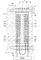
図1に示すように、本実施形態における組付状態の診断装置1は、回転軸の支持機構200の組付状態を診断する。
(First embodiment)
As shown in FIG. 1, the assembled
支持機構200は、生産設備などに設けられる。支持機構200は、回転軸201と、複数の軸受202と、ハウジング203と、カバー204とを備える。
The
回転軸201は、軸心CLを中心に回転する。回転軸201には、調整用ナット205が取り付けられている。調整用ナット205は、予圧を調整するための部材である。
The
軸受202は、回転軸201を支持する部品である。軸受202は、摺動部を有する組付部品である。複数の軸受202は、回転軸201の軸方向CLの一方側と他方側にそれぞれ配置されている。本実施形態では、軸方向CLの一方側に、1つの軸受202が配置されている。軸方向CLの他方側に、2つの軸受202が配置されている。
The
軸受202は、内輪211と、外輪212と、転動体としての玉213とを備える。内輪211が回転軸201に固定されている。外輪212がハウジング203に固定されている。内輪211が、回転軸201とともに回転する。このとき、内輪211および外輪212と玉213とが、こすれながら滑り合う。すなわち、内輪211および外輪212のうち玉213とこすれながら滑り合う部分が摺動部となる。
The
ハウジング203は、複数の軸受202を支持する支持部材である。ハウジング203の内部に複数の軸受202が収納されている。カバー204は、ハウジング203の開口部を覆っている。カバー204は、固定用ナット206によって、ハウジング203に固定されている。
The
さらに、支持機構200は、内輪側スペーサ207と、外輪側スペーサ208とを備える。内輪側スペーサ207は、軸方向CLの一方側と他方側に位置する内輪211同士の間に挟まれている。外輪側スペーサ208は、軸方向CLの一方側と他方側に位置する外輪212同士の間に挟まれている。
Further, the
支持機構200の組付けでは、上記した回転軸201、軸受202、ハウジング203等の支持機構200の各部品が図1に示すように組み合わされた後に、予圧調整が行われる。予圧は、軸受202の内部すきまをなくすために、軸受202にあらかじめ加える荷重のことである。予圧調整は、例えば、軸方向CLの一方側と他方側に位置する内輪211同士を押しつけるように、調整用ナット205を締め上げることで行われる。内輪211と外輪212を軸心CLの方向にずらすことで、内輪211と外輪212の間で玉213が押しつけられた状態となる。
In assembling the
診断装置1は、センサ部2と、制御装置3と、表示装置4とを備えている。
The
センサ部2は、軸受202から外部に向かう熱流束を検出する。センサ部2は、軸受202から外部に向かう熱流束に応じたセンサ信号を制御装置3に向けて出力する。センサ部2は、ハウジング203の表面に取り付けられている。センサ部2の構造の詳細については後述する。
The
本実施形態では、センサ部2として、2つのセンサ部2a、2bが用いられている。一方のセンサ部2aは、軸心CL方向の一方側の軸受202に対応して配置されている。他方のセンサ部2bは、軸心CL方向の他方側の軸受202に対応して配置されている。
In the present embodiment, two
制御装置3の入力側に、センサ部2が接続されている。制御装置3は、軸受202の組付状態の診断制御を行う。ここでいう軸受202の組付状態とは、軸受202の予圧状態である。この診断制御は、センサ部2の検出結果に基づいて、軸受202の組付状態が適正か否かを判定する制御である。したがって、制御装置3が、熱流束センサ10の検出結果に基づいて、軸受202の組付状態が適正か否かを判定する判定部を構成している。
The
制御装置3の出力側には、表示装置4が接続されている。制御装置3は、判定結果を表示装置4に表示させる。制御装置3は、マイクロコンピュータ、記憶装置等を有して構成される。
A
表示装置4は、判定結果をユーザに報知するための報知装置である。表示装置4としては、液晶ディスプレイ等が用いられる。
The
次に、センサ部2の構造について説明する。図2に示すように、センサ部2は、2つの熱流束センサ10と、熱緩衝体11と、放熱体12とを備えている。2つの熱流束センサ10、熱緩衝体11および放熱体12は、いずれも平板状である。
Next, the structure of the
2つの熱流束センサ10の内部構造は同じである。2つの熱流束センサ10の一方が第1熱流束センサ10aである。2つの熱流束センサ10の他方が第2熱流束センサ10bである。
The internal structure of the two
第1熱流束センサ10aは、ハウジング203の外面に接して配置されている。第2熱流束センサ10bは、第1熱流束センサ10aに対してハウジング203、すなわち、軸受202から離れた側に配置されている。熱緩衝体11は、第1熱流束センサ10aと第2熱流束センサ10bの間に配置されている。放熱体12は、第2熱流束センサ10bに対して軸受202から離れた側に配置されている。すなわち、センサ部2は、軸受202に近い側から軸受202から離れた側に向かって、第1熱流束センサ10a、熱緩衝体11、第2熱流束センサ10b、放熱体12が順に配置されている。
The first
第1熱流束センサ10aは、第1熱流束センサ10aの軸受202側から熱緩衝体11側に向かって、第1熱流束センサ10aを通過する熱流束に応じた第1センサ信号を出力する。第2熱流束センサ10bは、第2熱流束センサ10bの熱緩衝体11側からその反対側に向かって、第2熱流束センサ10bを通過する熱流束に応じた第2センサ信号を出力する。第1熱流束センサ10aと第2熱流束センサ10bのそれぞれの平面形状は、形と大きさが同じ矩形である。
The first
熱緩衝体11は、所定の熱容量を有している。熱緩衝体11は、金属材料または樹脂材料で構成される。熱緩衝体11は、後述の通り、軸受202から外部に向かって放出される熱流束の変化を検出できる熱容量となるように、材質や厚さが設定されている。熱緩衝体11の平面形状は、第1熱流束センサ10aの平面形状と形と大きさが同じである。なお、熱緩衝体11の平面形状は、第1熱流束センサ10aの平面形状と形と大きさが異なっていてもよい。
The
放熱体12は、所定の熱容量を有している。放熱体12は、金属材料または樹脂材料で構成されている。放熱体12は、その熱容量が熱緩衝体11の熱容量よりも大きくなるように、材質や厚さが設定されている。放熱体12の平面形状は、第1熱流束センサ10a、熱緩衝体11、第2熱流束センサ10bの平面形状よりも大きくされている。放熱体12は、第1熱流束センサ10a、熱緩衝体11、第2熱流束センサ10bを挟んだ状態で、ハウジング203に固定されている。具体的には、放熱体12の外周部にネジ穴が形成されている。ネジ穴に挿入されたネジ13によって、放熱体12がハウジング203に固定されている。なお、ハウジング203と放熱体12との間には、スペーサ14が配置されている。ネジ13は、スペーサ14の内部を貫通している。
The
図3、4に示すように、1つの熱流束センサ10は、絶縁基材100、表面保護部材110、裏面保護部材120が一体化され、この一体化されたものの内部で第1、第2熱電部材130、140が交互に直列に接続された構造を有する。なお、図3では、表面保護部材110を省略している。絶縁基材100、表面保護部材110、裏面保護部材120は、フィルム状であって、熱可塑性樹脂等の可撓性を有する樹脂材料で構成されている。絶縁基材100は、その厚さ方向に貫通する複数の第1、第2ビアホール101、102が形成されている。第1、第2ビアホール101、102に互いに異なる金属や半導体等の熱電材料で構成された第1、第2熱電部材130、140が埋め込まれている。絶縁基材100の表面100aに配置された表面導体パターン111によって第1、第2熱電部材130、140の一方の接続部が構成されている。絶縁基材100の裏面100bに配置された裏面導体パターン121によって第1、第2熱電部材130、140の他方の接続部が構成されている。
As shown in FIGS. 3 and 4, in one
熱流束センサ10の厚さ方向にて、熱流束が熱流束センサ10を通過すると、第1、第2熱電部材130、140の一方の接続部と他方の接続部に温度差が生じる。これにより、ゼーベック効果によって第1、第2熱電部材130、140に熱起電力が発生する。熱流束センサ10は、この熱起電力、具体的には、電圧をセンサ信号として出力する。
When the heat flux passes through the
本実施形態では、第1熱流束センサ10aと第2熱流束センサ10bとは、それぞれを通過する熱流束が同じ大きさのとき、絶対値が同じ大きさのセンサ信号を出力するように構成されている。
In the present embodiment, the first
また、図2に示すように、第1熱流束センサ10aと第2熱流束センサ10bは、互いに直列に接続された状態で、制御装置3に電気的に接続されている。第1熱流束センサ10aと第2熱流束センサ10bは、軸受202からの熱流束が第1熱流束センサ10aと第2熱流束センサ10bを順に通過したときに、極性が反対の関係を有する第1センサ信号と第2センサ信号を出力するように配置されている。
Moreover, as shown in FIG. 2, the 1st
具体的には、第1、第2熱流束センサ10a、10bは、互いの表面保護部材110が対向するように配置されている。そして、図示していないが、第1、第2熱流束センサ10a、10bの表面導体パターン111同士が外部配線151を介して接続されている。第1、第2熱流束センサ10a、10bのそれぞれの裏面導体パターン121が外部配線152を介して制御装置3と接続されている。これにより、熱流束が第1熱流束センサ10aを裏面保護部材120側から表面保護部材110側に通過する場合には、当該熱流束が第2熱流束センサ10bを表面保護部材110側から裏面保護部材120側に通過するため、第1、第2熱流束センサ10a、10bから出力される第1、第2センサ信号の極性が反対となる。
Specifically, the first and second
なお、本実施形態では、第1、第2熱流束センサ10a、10bは、裏面保護部材120側から表面保護部材110側に向かって熱流束が通過した際、正のセンサ信号を出力する。このため、軸受202側から放熱体12側に向かって熱流束が流れると、第1熱流束センサ10aから正のセンサ信号が出力され、第2熱流束センサ10bから負のセンサ信号が出力される。
In the present embodiment, the first and second
そして、センサ部2は、第1センサ信号と第2センサ信号を合わせたセンサ信号を、制御装置3に向けて出力する。このとき、第1、第2熱流束センサ10a、10bを通過する熱流束同士の差が大きいと、センサ部2から出力されるセンサ信号が大きくなる。このような場合としては、例えば、対象物から放出される熱流束が急増したときが該当する。一方、第1、第2熱流束センサ10a、10bを通過する熱流束同士の差が小さいと、センサ部2から出力される出力が小さくなる。このような場合としては、例えば、対象物から放出される熱流束が減少したときや、対象物から放出される熱流束が一定で、所定時間が経過したときが該当する。
Then, the
次に、制御装置3が行う軸受202の組付状態の診断制御について説明する。
Next, diagnosis control of the assembled state of the
まず、センサ部2を通過する熱流束およびセンサ部2から出力されるセンサ信号について説明する。
First, the heat flux passing through the
支持機構200において、回転軸201が回転すると、軸受202の摺動部が発熱する。回転軸201の回転が停止すると、軸受202の摺動部は発熱しない。したがって、回転軸201が回転と停止とを繰り返すと、軸受202の摺動部から外部に向かう熱流束は増大と減少とを繰り返す。このため、軸受202が予圧適正の状態のとき、時間経過に伴うセンサ部2の出力値の変化を示す波形は、図5に示すように、回転軸201の回転と停止のサイクルにそって規則的に増減する波形になる。
In the
この理由は、次の通りである。上記の通り、回転軸201が回転と停止とを繰り返すとき、軸受202の摺動部から外部に向かう熱流束は増大と減少とを繰り返す。このとき、図2に示すように、第1熱流束センサ10aは、ハウジング203からの熱流束を遮るものがない。このため、第1熱流束センサ10aを通過する熱流束は、ハウジング203を流れる熱流束と同様に増減する。一方、図2に示すように、第2熱流束センサ10bは、第1熱流束センサ10a側に熱緩衝体11が配置されている。熱緩衝体11は畜熱と放熱とを行う。このため、第2熱流束センサ10bを熱流束が通過しない。または、第2熱流束センサ10bを通過する熱流束は、第1熱流束センサ10aを通過する熱流束に対して遅れて緩やかに増減する。センサ部2から制御装置3に向けて出力されるセンサ信号は、第1センサ信号と第2センサ信号を合わせたものである。このため、センサ部2の出力値は、回転軸201の回転と停止のサイクルにそって規則的に増減する。
The reason for this is as follows. As described above, when the
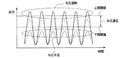
軸受202が予圧過剰の状態のとき、軸受202の摺動部での摩擦が大きくなる。このため、回転軸201の回転時では、軸受202の摺動部の発熱量が大きくなる。したがって、軸受202が予圧過剰の状態のときでは、図6中の実線で示すように、波線で示す予圧適正のときのセンサ部2の出力値と比較して、回転時におけるセンサ部2の出力値が大きくなる。
When the
また、軸受202が予圧不足の状態のとき、軸受202の摺動部での摩擦が小さくなる。このため、回転軸201の回転時では、軸受202の摺動部の発熱量が小さくなる。したがって、軸受202が予圧不足の状態のときでは、図6中の一点鎖線で示すように、波線で示す予圧適正のときのセンサ部2の出力値と比較して、回転時におけるセンサ部2の出力値が小さくなる。
Further, when the
このように、軸受202の予圧状態が予圧適正、予圧過剰、予圧不足のそれぞれのときによって、センサ部2の出力値が異なる。このことから、予圧適正の状態と予圧過剰の状態とを判別するための上限閾値と、予圧適正の状態と予圧不足の状態とを判別するための下限閾値とを予め設定しておく。そして、センサ部2の出力値と上限閾値、下限閾値とを比較する。これにより、軸受202の予圧状態が適正か否かを判定できる。
Thus, the output value of the
そこで、図7に示すように、制御装置3は、センサ部2の検出結果に基づいて、組付状態の診断を行う。なお、図7中に示した各ステップは、各種機能を実現する機能実現部を構成するものである。また、この診断は、センサ部2aとセンサ部2bのそれぞれの検出結果毎に行われる。
Therefore, as shown in FIG. 7, the
具体的には、ステップS1で、センサ部2の検出値を取得する。ここでは、所定の時刻におけるセンサ部2の出力値(具体的には、電圧値)を取得する。なお、センサ部2の出力値をそのまま用いる替わりに、出力値を補正した補正値を検出値として取得してもよい。
Specifically, the detection value of the
続いて、ステップS2で、検出値と予め記憶装置に記憶された上限閾値、下限閾値とを比較して、検出値が適正範囲内であるか否かを判定する。検出値が上限閾値と下限閾値の間の値である場合、すなわち、検出値が適正範囲内である場合、YES判定して、ステップS3に進む。ステップS3で、表示装置4に予圧状態が適正であるとの表示をさせるための制御信号を出力する。これにより、表示装置4に予圧状態が適正である旨の表示がされる。
Subsequently, in step S2, the detected value is compared with an upper limit threshold value and a lower limit threshold value stored in advance in the storage device, and it is determined whether or not the detected value is within an appropriate range. If the detected value is a value between the upper limit threshold and the lower limit threshold, that is, if the detected value is within the appropriate range, a YES determination is made and the process proceeds to step S3. In step S3, a control signal for causing the
一方、ステップS2で、検出値が上限閾値を超えた場合、または、検出値が下限閾値よりも低い場合、すなわち、検出値が適正範囲外の場合、NO判定してステップS4に進む。ステップS4で、表示装置4に予圧状態が不適正であるとの表示をさせるための制御信号を出力する。これにより、表示装置4に予圧状態が不適正である旨の表示がされる。なお、検出値が適正範囲外の場合、予圧状態が予圧過剰の状態または予圧不足の状態である旨の表示をさせるようにしてもよい。
On the other hand, if the detected value exceeds the upper limit threshold value in step S2, or if the detected value is lower than the lower limit threshold value, that is, if the detected value is outside the proper range, NO is determined and the process proceeds to step S4. In step S4, a control signal for causing the
以上の説明の通り、本実施形態の診断装置1によれば、軸受202の予圧状態が適正か否かを診断できる。
As described above, according to the
また、本実施形態の診断装置1においては、センサ部2は、第1熱流束センサ10aと第2熱流束センサ10bの間に熱緩衝体11が配置されている。制御装置3は、第1熱流束センサ10aが出力する第1センサ信号と第2熱流束センサ10bが出力する第2センサ信号に基づいて、軸受202の予圧状態が適正か否かを判定する。
Moreover, in the
熱緩衝体11は熱の蓄積と放出を行う。このため、軸受202の摺動部から放出される熱流束が変化したとき、第2熱流束センサ10bを通過する熱流束は、第1熱流束センサ10aを通過する熱流束よりも、遅れて緩やかに変化する。したがって、第1センサ信号と第2センサ信号の相違より、軸受202の摺動部から放出される熱流束の変化を検出できる。
The
ところで、本実施形態のセンサ部2の替わりに、1つの熱流束センサ10のみを用いても、軸受202の摺動部から放出される熱流束を検出することができる。
By the way, it is possible to detect the heat flux emitted from the sliding portion of the
しかし、この場合、回転軸の支持機構200の周りの環境温度が変化すると、環境温度の影響を受けて、熱流束センサ10を通過する熱流束も変化する。すなわち、軸受202の摺動部での発熱量が同じであっても、環境温度が高いときと低いときでは、環境温度が低いときの方が、熱流束センサ10を通過する熱流束が大きくなる。
However, in this case, when the environmental temperature around the rotating
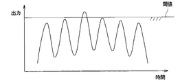
このため、図8に示すように、軸受202の予圧状態が適正な状態であっても、一日の環境温度の変動によって、センサ部2の出力値が閾値を超えてしまう場合がある。この場合、制御装置3は、軸受202の予圧状態が適正ではないと誤判定してしまう。また、この誤判定を回避するために、環境温度の変動を考慮して、上限閾値を高く設定することが考えられる。しかし、この場合では、軸受202の予圧状態が予圧過剰な状態であっても、適正と誤判定してしまう。
For this reason, as shown in FIG. 8, even if the preload state of the
これに対して、本実施形態のセンサ部2の第1熱流束センサ10aと第2熱流束センサ10bは、熱緩衝体11の両側に配置されている。したがって、両者は比較的近い位置に配置されている。また、センサ部2の周りの環境温度の変化は、通常、一日という長期間にわたって緩やかに生じる。このため、第1熱流束センサ10aと第2熱流束センサ10bの間に熱緩衝体11が配置されていても、第1熱流束センサ10aと第2熱流束センサ10bが環境温度から受ける影響は同じまたは同じに近い。第1熱流束センサ10aと第2熱流束センサ10bのそれぞれは、同じ環境温度の影響を受けた熱流束に応じたセンサ信号を出力する。第1熱流束センサ10aと第2熱流束センサ10bにおいて、同じ熱流束の大きさに対する出力の絶対値を同じである。したがって、第1熱流束センサ10aと第2熱流束センサ10bの出力の和を用いることで、センサ部2の検出結果に対する環境温度の影響を除外(すなわち、キャンセル)できる。
On the other hand, the 1st
このため、軸受202が予圧適正の状態のときのセンサ部2の出力波形は、図5に示す予圧適正のときの出力波形のように、環境温度の影響が除外されたものとなる。これにより、一日の環境温度の変動による誤判定を回避できる。また、環境温度の変動を考慮して、上限閾値を高く設定する必要がなくなる。
For this reason, the output waveform of the
よって、本実施形態の診断装置1によれば、軸受202の組付状態の診断を高精度に行うことができる。なお、第1熱流束センサ10aと第2熱流束センサ10bにおいて、同じ熱流束の大きさに対する出力の絶対値は必ずしも同じでなくてもよい。両者の出力の絶対値が近ければよい。この場合でも、第1熱流束センサ10aと第2熱流束センサ10bの出力の和を用いることで、センサ部2の検出結果に対する環境温度の影響を低減できる。
Therefore, according to the
また、本実施形態のセンサ部2において、第1熱流束センサ10aと第2熱流束センサ10bは、軸受202の摺動部からの熱流束が第1熱流束センサ10aと第2熱流束センサ10bを順に通過したときに、極性が反対の関係を有する第1センサ信号と第2センサ信号を出力する。第1熱流束センサ10aと第2熱流束センサ10bは、互いに直列に接続された状態で、制御装置3に電気的に接続されている。これにより、第1センサ信号と第2センサ信号を合わせたセンサ信号を、センサ部2から制御装置3に向けて出力することができる。このため、制御装置3での第1センサ信号と第2センサ信号の和の演算を省略できる。すなわち、制御装置3の演算処理を簡素化できる。
In the
ところで、センサ部2は、放熱体12を持たない構成であってもよい。しかし、センサ部2が放熱体12を持たない場合、第2熱流束センサ10bの表面に風が当たる等の理由により、第2熱流束センサ10bの表面温度が瞬間的に変化してしまう。これが、センサ部2を通過する熱流束に影響する。このため、センサ部2の熱流束の検出精度が低下してしまう。
By the way, the
これに対して、本実施形態のセンサ部2は、所定の熱容量を有する放熱体12を備えている。これにより、短期間でセンサ部2の表面温度が変化する場合であっても、放熱体12での蓄熱と放熱によって、第2熱流束センサ10bの温度変化を抑制できる。このため、センサ部2の熱流束の検出精度を向上させることができる。
On the other hand, the
また、本実施形態のセンサ部2において、放熱体12の熱容量は、熱緩衝体11の熱容量よりも大きくされている。これにより、軸受202の摺動部から大きな熱が放出されたときでも、軸受202の摺動部から放熱体12に向かって熱を流すことができる。このため、センサ部2の内部に熱がこもることを抑制できる。
Further, in the
(第2実施形態)
図9に示すように、本実施形態における組付状態の診断装置1は、移送装置300の組付状態を診断する。
(Second Embodiment)
As shown in FIG. 9, the assembled
図9、10に示すように、移送装置300は、ボールねじ301と、支持部材302と、モータ303と、台座304と、レール305と、ガイドブロック306とを備える。なお、図10では、理解をし易くするために、支持部材302を省略して示してある。
As shown in FIGS. 9 and 10, the
ボールねじ301は、回転運動を直線運動に変換する機械要素部品である。ボールねじ301は、ねじ軸311と、ナット312と、ボール313とを有している。ねじ軸311とナット312の間にボール313が入れられている。ねじ軸311が回転すると、ナット312が直線運動をする。支持部材302は、ねじ軸311の軸方向の両端部を支持している。モータ303は、ねじ軸311を回転させる動力源である。
The
台座304は、移送したい装置等を搭載するためのものである。台座304は、ねじ軸311の軸方向と直交する方向(すなわち、図9の上下方向)を長手方向とする平面矩形状とされている。台座304は、長手方向の略中央部がナット312と連結されている。台座304は、長手方向の両端部がガイドブロック306と連結されている。
The
レール305は、直線状部材である。レール305は、2本用いられており、図10に示すように、ベースプレート307に固定されている。ガイドブロック306は、レール305に係合されている。ガイドブロック306は、レール305に沿って移動するガイド部材である。ガイドブロック306がレール305上を移動するとき、レール305とガイドブロック306は、互いにこすれ合う。レール305のうちガイドブロック306とこすれ合う部分が摺動部である。したがって、本実施形態では、2本のレール305が、摺動部を有する組付部品を構成している。
The
このような移送装置300は、モータ303によってねじ軸311が回転すると、台座304がナット312と共にレール305に沿って走行する。これにより、所望箇所に台座304を移送することできる。
In such a
移送装置300の組付けでは、上記したレール305、ガイドブロック306等の移送装置300の各構成部品が図9、10に示すように組み付けられる。このとき、2本のレール305は平行に設置される。
In assembling the
本実施形態の診断装置1の構成は、第1実施形態の診断装置1と同じである。センサ部2は、移送装置300のガイドブロック306の表面に取り付けられている。センサ部2は、図示しないが、ガイドブロック306に近い側からガイドブロック306から離れた側に向かって、第1熱流束センサ10a、熱緩衝体11、第2熱流束センサ10b、放熱体12が順に配置されている。
The configuration of the
制御装置3は、2本のレール305の組付状態が適正か否かを診断する。ここでいう2本のレール305の組付状態とは、2本のレール305の設置状態である。制御装置3は、2本のレール305の設置状態が適正か否か、すなわち、2本のレール305の平行性が良いか悪いかを診断する。
The
次に、本実施形態の組付状態の診断制御について説明する。 Next, the assembly state diagnosis control of this embodiment will be described.
まず、センサ部2から出力されるセンサ信号について説明する。移送装置300は、台座304の走行と停止を1サイクルとする稼働サイクルを繰り返す。台座304の走行中は、レール305の摺動部とガイドブロック306の摺動部の摩擦によって、センサ部2の出力値が増加する。台座304の停止中は、センサ部2の出力値が低下する。
First, the sensor signal output from the
このため、2本のレール305の平行性が良い状態のときの時間経過に伴うセンサ部2の出力値の変化を示す波形は、図11に示すように、移送装置300の稼働サイクルにそって規則的に増減する波形になる。
Therefore, the waveform indicating the change in the output value of the
2本のレール305の少なくとも一部が、うねっていたり、浮いていたりすること等の理由によって、2本のレール305に局部的に平行でない部分が生じる場合がある。このように、2本のレール305の平行性が悪い状態では、摺動部の摩擦が大きくなり、摺動部からの熱流束が大きくなる。このため、平行性が悪い状態のときの時間経過に伴うセンサ部2の出力値の変化を示す波形は、図12に示すように、平行性が良い状態のときよりも出力のピーク値が大きな波形となる。
A portion that is not locally parallel to the two
このように、2本のレール305の平行性が良い状態のときと悪い状態のときでは、センサ部2の出力値が異なる。このことから、2本のレール305の平行性が良い状態と悪い状態とを判別するための閾値を予め設定しておき、センサ部2の出力値と閾値とを比較する。これにより、2本のレール305の組付状態が適正か否かを判定できる。
Thus, the output value of the
そこで、本実施形態の診断装置1においても、第1実施形態と同様に、制御装置3は、センサ部2の検出結果に基づいて、組付状態の診断を行う。具体的には、制御装置3は、センサ部2の検出値と閾値とを比較する。図12中の波線のように、検出値が閾値を超えていない場合、組付状態が適正であると判定する。一方、図12中の実線のように、検出値が閾値を超えている場合、組付状態が適正でないと判定する。このようにして、本実施形態の診断装置1によれば、2本のレール305の組付状態が適正か否かを診断することができる。
Therefore, also in the
また、本実施形態の診断装置1に用いるセンサ部2は、第1実施形態のセンサ部2と同じ構成のものである。このため、本実施形態の診断装置1においても、第1実施形態の診断装置1と同様の効果を奏する。
Moreover, the
なお、本実施形態の診断装置1に用いるセンサ部2として、第1熱流束センサ10のみを用いてもよい。
In addition, you may use only the 1st
(第3実施形態)
本実施形態は、第1実施形態に対して、センサ部2の構成を変更したものである。診断装置1のその他の構成は第1実施形態と同じである。
(Third embodiment)
In the present embodiment, the configuration of the
図13に示されるように、本実施形態のセンサ部2は、平板状の受熱体16を有している。受熱体16は、第1熱流束センサ10aよりもハウジング203、すなわち、軸受202側に配置されている。したがって、受熱体16は、軸受202と第1熱流束センサ10aとの間に配置されている。
As shown in FIG. 13, the
受熱体16は、熱緩衝体11や放熱体12と同様に、所定の熱容量を有している。受熱体16は、金属材料または樹脂材料で構成される。受熱体16は、その熱容量が熱緩衝体11および放熱体12より小さくなるように、材質や厚さが設定されている。受熱体16の平面形状は、第1熱流束センサ10aの平面形状と形と大きさが同じである。なお、受熱体16の平面形状は、第1熱流束センサ10aの平面形状と形と大きさが異なっていてもよい。
The
本実施形態のセンサ部2では、受熱体16の蓄熱と放熱によって、検出目的ではないノイズ等の短期的に生じる熱流束の変化が第1、第2熱流束センサ10a、10bに影響することを抑制できる。
In the
また、本実施形態のセンサ部2では、受熱体16の熱容量を小さく設定している。このため、本実施形態のセンサ部2は、検出目的である回転軸201の回転と停止による熱流束変化を検出できる。すなわち、本実施形態のセンサ部2では、受熱体16の熱容量は、回転軸201の回転と停止による熱流束変化を検出できる大きさに設定されている。
Moreover, in the
よって、本実施形態の診断装置1は、軸受202の予圧状態が適正か否かの診断を高精度に行うことができる。なお、第2実施形態においても、センサ部2が受熱体16を有する構成としてもよい。これにより、本実施形態と同様の効果を奏する。
Therefore, the
(第4実施形態)
本実施形態は、第1実施形態に対して、センサ部2の構成を変更したものである。診断装置1のその他の構成は第1実施形態と同じである。
(Fourth embodiment)
In the present embodiment, the configuration of the
図14に示されるように、本実施形態のセンサ部2は、第1、第2熱流束センサ10a、10bが、折り曲げられた形状を有する屈曲形状部10cを介して、つながっている。屈曲形状部10cは、第1、第2熱流束センサ10a、10bと同様に、絶縁基材100、表面保護部材110、裏面保護部材120が積層された構造である。このように、本実施形態のセンサ部2は、第1、第2熱流束センサ10a、10bが一体化されている。
As shown in FIG. 14, in the
換言すると、本実施形態のセンサ部2は、1つの熱流束センサ10が熱緩衝体11を挟むように折り曲げられた構造を有する。熱流束センサ10は、上述の通り、絶縁基材100、表面保護部材110、裏面保護部材120がそれぞれ可撓性を有する樹脂材料で構成されている。このため、熱流束センサ10を容易に折り曲げることができる。これにより、第1熱流束センサ10aと第2熱流束センサ10bの間に熱緩衝体11が配置された構成が実現されている。
In other words, the
第1、第2熱流束センサ10a、10bは、互いの裏面導体パターン121同士がつながっている。第1、第2熱流束センサ10a、10bは、外部配線151ではなく、熱流束センサ10の内部の配線パターンによって電気的に接続されている。なお、第1、第2熱流束センサ10a、10bは、互いの表面導体パターン111同士がつながっていてもよい。
In the first and second
これによれば、第1、第2熱流束センサ10a、10bを1つの熱流束センサ10で構成しており、第1熱流束センサ10aと第2熱流束センサ10bとを接続するための外部配線151を無くすことができる。したがって、部品点数の削減を図ることができる。
According to this, the first and second
(他の実施形態)
本発明は上記した実施形態に限定されるものではなく、下記のように、特許請求の範囲に記載した範囲内において適宜変更が可能である。
(Other embodiments)
The present invention is not limited to the above-described embodiment, and can be appropriately modified within the scope described in the claims as follows.
(1)第1実施形態の診断装置1は、軸受202の組付状態を診断対象としていた。第2実施形態の診断装置1は、2本のレール305の組付状態を診断対象としていた。診断装置1の診断対象は、これらに限定されない。診断装置1は、他の組付部品の組付状態を診断対象とすることができる。ただし、他の組付部品は、組付状態が適正のときと不適正のときで、摺動部からの熱流束の大きさが異なるものである。
(1) The
(2)第1〜第3実施形態のセンサ部2では、第1熱流束センサ10aと第2熱流束センサ10bが、互いに直列に接続された状態で、制御装置3に電気的に接続されていたが、制御装置3に対して並列に接続されていてもよい。
(2) In the
(3)第1〜第3実施形態のセンサ部2では、極性が反対の関係を有する第1センサ信号と第2センサ信号を出力するように、第1熱流束センサ10aと第2熱流束センサ10bが配置されていたが、第1熱流束センサ10aと第2熱流束センサ10bの配置はこれに限定されない。極性が同じ第1センサ信号と第2センサ信号を出力するように、第1熱流束センサ10aと第2熱流束センサ10bが配置されていてもよい。この場合、第1熱流束センサ10aと第2熱流束センサ10bは、制御装置3に対して並列に接続される。また、診断制御においては、制御装置3は、第1センサ信号と第2センサ信号の差を演算する。これにより、第1、第2実施形態と同様に、診断制御を行うことができる。
(3) In the
(4)第1〜第3実施形態のセンサ部2においては、熱流束センサ10の絶縁基材100、表面保護部材110、裏面保護部材120が、樹脂材料以外の可撓性を有する絶縁材料で構成されていてもよい。さらに、絶縁基材100、表面保護部材110、裏面保護部材120が、可撓性を持たない絶縁材料で構成されていてもよい。また、熱流束センサ10が、表面保護部材110、裏面保護部材120を持たない構造であってもよい。また、熱流束センサ10として、上記した構成とは別の構成のものを用いてもよい。
(4) In the
(5)第4実施形態のセンサ部2においては、熱流束センサ10の絶縁基材100、表面保護部材110、裏面保護部材120が、樹脂材料以外の可撓性を有する絶縁材料で構成されていてもよい。また、熱流束センサ10が、表面保護部材110、裏面保護部材120を持たない構造であってもよい。この場合、第1熱流束センサ10aと第2熱流束センサ10bは、絶縁基材100で構成された屈曲形状部10cを介して、つながっている構造となる。要するに、屈曲形状部10cは、絶縁基材100と同じ絶縁材料を含んで構成されていればよい。
(5) In the
(6)上記各実施形態のセンサ部2は、2つの熱流束センサ10と、熱緩衝体11と、放熱体12とを備えていたが、放熱体12を備えていなくてもよい。この場合、センサ部2の固定は、他の固定部材を用いたり、接着剤を用いたりして行われる。
(6) Although the
(7)上記各実施形態では、センサ部2のセンサ信号として電圧を用いたが、電流を用いてもよい。
(7) In each of the above embodiments, a voltage is used as a sensor signal of the
(8)上記各実施形態は、互いに無関係なものではなく、組み合わせが明らかに不可な場合を除き、適宜組み合わせが可能である。また、上記各実施形態において、実施形態を構成する要素は、特に必須であると明示した場合および原理的に明らかに必須であると考えられる場合等を除き、必ずしも必須のものではないことは言うまでもない。
(まとめ)
上記各実施形態の一部または全部で示された第1の観点によれば、組付状態の診断装置は、センサ部と、判定部とを備える。センサ部は、摺動部から外部に向かって流れる熱流束を検出する。判定部は、センサ部が検出した検出結果に基づいて、組付部品の組付状態が適正か否かを判定する。
(8) The above embodiments are not irrelevant to each other, and can be appropriately combined unless the combination is clearly impossible. In each of the above-described embodiments, it is needless to say that elements constituting the embodiment are not necessarily essential unless explicitly stated as essential and clearly considered essential in principle. Yes.
(Summary)
According to the 1st viewpoint shown by one part or all part of said each embodiment, the diagnostic apparatus of an assembly state is provided with a sensor part and a determination part. A sensor part detects the heat flux which flows toward the exterior from a sliding part. The determination unit determines whether or not the assembled state of the assembled component is appropriate based on the detection result detected by the sensor unit.
また、第2の観点によれば、センサ部は、第1熱流束センサと、第2熱流束センサと、第1熱流束センサと第2熱流束センサの間に配置された熱緩衝体とを有する。第1熱流束センサは、第1熱流束センサを通過する熱流束に応じた第1センサ信号を出力する。第2熱流束センサは、第2熱流束センサを通過する熱流束に応じた第2センサ信号を出力する。判定部は、第1センサ信号と第2センサ信号に基づいて、対象装置の異常の有無を判定する。 Further, according to the second aspect, the sensor unit includes a first heat flux sensor, a second heat flux sensor, and a thermal buffer disposed between the first heat flux sensor and the second heat flux sensor. Have. The first heat flux sensor outputs a first sensor signal corresponding to the heat flux passing through the first heat flux sensor. The second heat flux sensor outputs a second sensor signal corresponding to the heat flux passing through the second heat flux sensor. The determination unit determines whether there is an abnormality in the target device based on the first sensor signal and the second sensor signal.
第2の観点では、センサ部は、第1熱流束センサと第2熱流束センサの間に熱緩衝体が配置されている。このため、摺動部から放出される熱流束が変化したとき、第2熱流束センサを通過する熱流束は、第1熱流束センサを通過する熱流束よりも、遅れて緩やかに変化する。したがって、第1センサ信号と第2センサ信号の相違より、摺動部から放出される熱流束の変化を検出できる。 In the second aspect, in the sensor unit, a thermal buffer is disposed between the first heat flux sensor and the second heat flux sensor. For this reason, when the heat flux emitted from the sliding portion changes, the heat flux passing through the second heat flux sensor changes more slowly with a delay than the heat flux passing through the first heat flux sensor. Therefore, a change in the heat flux emitted from the sliding portion can be detected from the difference between the first sensor signal and the second sensor signal.
そして、第1熱流束センサと第2熱流束センサは、熱緩衝体の両側に配置されており、両者は比較的近い位置に配置されている。また、センサ部が設置される環境の温度である環境温度の変化は、通常、長期間にわたって緩やかに生じる。このため、第1熱流束センサと第2熱流束センサが環境温度から受ける影響は同じまたは同じに近い。第1熱流束センサと第2熱流束センサのそれぞれは、同じまたは同じに近い環境温度の影響を受けた熱流束に応じたセンサ信号を出力する。したがって、両者のセンサ信号を用いることで、センサ部の検出結果に対する環境温度の影響を除外もしくは低減することができる。よって、第2の観点の診断装置によれば、組付部品の組付状態の診断を高精度に行うことができる。 And the 1st heat flux sensor and the 2nd heat flux sensor are arranged at the both sides of a thermal buffer, and both are arranged at a relatively near position. In addition, a change in environmental temperature, which is the temperature of the environment where the sensor unit is installed, usually occurs gradually over a long period of time. For this reason, the influence which a 1st heat flux sensor and a 2nd heat flux sensor receive from environmental temperature is the same or close to the same. Each of the first heat flux sensor and the second heat flux sensor outputs a sensor signal corresponding to the heat flux affected by the same or similar environmental temperature. Therefore, by using both sensor signals, the influence of the environmental temperature on the detection result of the sensor unit can be excluded or reduced. Thus, according to the diagnostic device of the second aspect, it is possible to diagnose the assembled state of the assembled component with high accuracy.
また、第3の観点によれば、センサ部は、第2熱流束センサよりも組付部品から離れた側に配置され、所定の熱容量を有する放熱体を有する。 Moreover, according to the 3rd viewpoint, a sensor part is arrange | positioned rather than the 2nd heat flux sensor at the side far | separated from the assembly | attachment components, and has a heat radiator which has a predetermined | prescribed heat capacity.
これによると、短期間でセンサ部の表面温度が変化する場合であっても、放熱体での蓄熱と放熱によって、第2熱流束センサの温度変化を抑制できる。このため、センサ部の熱流束の検出精度を向上させることができる。 According to this, even if it is a case where the surface temperature of a sensor part changes in a short period, the temperature change of a 2nd heat flux sensor can be suppressed by the thermal storage and heat dissipation with a heat radiator. For this reason, the detection accuracy of the heat flux of a sensor part can be improved.
また、第4の観点によれば、放熱体の熱容量は、熱緩衝体の熱容量よりも大きくされている。これによると、摺動部から大きな熱が放出されたときでも、摺動部から放熱体に向かって熱を流すことができる。このため、センサ部の内部に熱がこもることを抑制できる。 Moreover, according to the 4th viewpoint, the heat capacity of a heat sink is made larger than the heat capacity of a heat buffer. According to this, even when a large amount of heat is released from the sliding portion, heat can be flowed from the sliding portion toward the heat radiating body. For this reason, it is possible to suppress heat from being trapped inside the sensor unit.
また、第5の観点によれば、センサ部は、第1熱流束センサよりも組付部品側に配置された受熱体を有している。受熱体の熱容量は、熱緩衝体の熱容量よりも小さくされている。 Moreover, according to the 5th viewpoint, the sensor part has the heat receiving body arrange | positioned rather than the 1st heat flux sensor at the assembly | attachment component side. The heat capacity of the heat receiving body is smaller than the heat capacity of the heat buffer.
これによると、受熱体の蓄熱と放熱によって、検出目的ではないノイズ等の短期的に生じる熱流束の変化が第1、第2熱流束センサに影響することを抑制できる。また、受熱体の熱容量を小さく設定することで、センサ部によって検出目的である摺動部から放出される熱流束の変化を検出できる。 According to this, it is possible to suppress changes in heat flux that occurs in the short term, such as noise that is not the purpose of detection, from affecting the first and second heat flux sensors due to heat storage and heat dissipation of the heat receiving body. In addition, by setting the heat capacity of the heat receiving body small, it is possible to detect a change in the heat flux emitted from the sliding portion, which is the detection purpose, by the sensor unit.
また、第6の観点によれば、センサ部は、摺動部からの熱流束が第1熱流束センサと第2熱流束センサを順に通過したときに、第1センサ信号と第2センサ信号の極性が反対となるように、第1熱流束センサと第2熱流束センサとが配置されている。第1熱流束センサと第2熱流束センサは、電気的に直列に接続されている。 According to the sixth aspect, when the heat flux from the sliding portion sequentially passes through the first heat flux sensor and the second heat flux sensor, the sensor unit is configured to output the first sensor signal and the second sensor signal. The first heat flux sensor and the second heat flux sensor are arranged so that the polarities are opposite. The first heat flux sensor and the second heat flux sensor are electrically connected in series.
これによると、センサ部は、第1センサ信号と第2センサ信号を合わせたセンサ信号を出力することができる。このため、第1センサ信号と第2センサ信号の和の演算処理を不要にできる。 According to this, the sensor part can output the sensor signal which combined the 1st sensor signal and the 2nd sensor signal. For this reason, the calculation process of the sum of a 1st sensor signal and a 2nd sensor signal can be made unnecessary.
また、第7の観点によれば、第1熱流束センサと第2熱流束センサのそれぞれは、可撓性を有するフィルム状の絶縁基材と、複数の第1熱電部材と、複数の第2熱電部材とを有して構成される。複数の第1熱電部材と複数の第2熱電部材は、第1熱電部材と第2熱電部材とが交互に直列に接続されている。第1熱流束センサと第2熱流束センサは、絶縁材料を含んで構成された屈曲形状部を介して、つながっている。 According to the seventh aspect, each of the first heat flux sensor and the second heat flux sensor includes a flexible film-like insulating base, a plurality of first thermoelectric members, and a plurality of second heat flux sensors. And a thermoelectric member. In the plurality of first thermoelectric members and the plurality of second thermoelectric members, the first thermoelectric members and the second thermoelectric members are alternately connected in series. The first heat flux sensor and the second heat flux sensor are connected via a bent portion that includes an insulating material.
これによると、第1熱流束センサと第2熱流束センサとを接続するための外部配線を不要にできる。 According to this, it is possible to eliminate the need for external wiring for connecting the first heat flux sensor and the second heat flux sensor.
1 組付状態の診断装置
2 センサ部
3 制御装置
10a 第1熱流束センサ
10b 第2熱流束センサ
11 熱緩衝体
12 放熱体
16 受熱体
202 軸受
305 レール
DESCRIPTION OF
Claims (6)
前記摺動部から外部に向かって流れる熱流束を検出するセンサ部(2)と、
前記センサ部が検出した検出結果に基づいて、前記組付部品の組付状態が適正か否かを判定する判定部(3)とを備え、
前記センサ部は、
第1熱流束センサ(10a)と、
前記第1熱流束センサよりも前記組付部品から離れた側に配置された第2熱流束センサ(10b)と、
前記第1熱流束センサと前記第2熱流束センサの間に配置され、所定の熱容量を有する熱緩衝体(11)とを有し、
前記第1熱流束センサは、前記第1熱流束センサの前記組付部品側から前記第1熱流束センサの前記熱緩衝体側に向かって前記第1熱流束センサを通過する熱流束に応じた第1センサ信号を出力し、
前記第2熱流束センサは、前記第2熱流束センサの前記熱緩衝体側から前記第2熱流束センサの前記熱緩衝体側の反対側に向かって前記第2熱流束センサを通過する熱流束に応じた第2センサ信号を出力し、
前記判定部は、前記第1センサ信号と前記第2センサ信号に基づいて、前記組付部品の組付状態が適正か否かを判定する組付状態の診断装置。 An assembly state diagnosis device for diagnosing the assembly state of assembly parts (202, 305) having a sliding part,
A sensor part (2) for detecting a heat flux flowing outward from the sliding part;
A determination unit (3) for determining whether or not an assembly state of the assembly component is appropriate based on a detection result detected by the sensor unit ;
The sensor unit is
A first heat flux sensor (10a);
A second heat flux sensor (10b) disposed on the side farther from the assembly component than the first heat flux sensor;
A thermal buffer (11) disposed between the first heat flux sensor and the second heat flux sensor and having a predetermined heat capacity;
The first heat flux sensor corresponds to a heat flux that passes through the first heat flux sensor from the assembly component side of the first heat flux sensor toward the heat buffer side of the first heat flux sensor. 1 sensor signal is output,
The second heat flux sensor is responsive to the heat flux passing through the second heat flux sensor from the heat buffer side of the second heat flux sensor toward the opposite side of the heat buffer side of the second heat flux sensor. Output a second sensor signal,
The determination unit, wherein the first sensor signal based on the second sensor signal, the diagnostic device of the assembled state that assembled state of the parts with the set is to determine proper or.
前記受熱体の熱容量は、前記熱緩衝体の熱容量よりも小さくされている請求項1ないし3のいずれか1つに記載の組付状態の診断装置。 The sensor unit includes a heat receiving body (16) disposed on the assembly component side with respect to the first heat flux sensor,
The heat capacity of the heat receiving body is diagnostic apparatus assembled state according to any one of 3 claims 1 and is smaller than the thermal capacity of the heat cushion.
前記第1熱流束センサと前記第2熱流束センサは、電気的に直列に接続されている請求項1ないし4のいずれか1つに記載の組付状態の診断装置。 When the heat flux from the sliding portion sequentially passes through the first heat flux sensor and the second heat flux sensor, the sensor unit has opposite polarities of the first sensor signal and the second sensor signal. The first heat flux sensor and the second heat flux sensor are arranged so that
The assembled diagnosis apparatus according to any one of claims 1 to 4 , wherein the first heat flux sensor and the second heat flux sensor are electrically connected in series.
少なくとも絶縁材料で構成され、可撓性を有するフィルム状の絶縁基材(100)と、
前記絶縁基材に形成され、熱電材料で構成された複数の第1熱電部材(130)と、
前記絶縁基材に形成され、前記第1熱電部材と異なる熱電材料で構成された複数の第2熱電部材(140)とを有し、
前記複数の第1熱電部材と複数の前記第2熱電部材は、前記第1熱電部材と前記第2熱電部材とが交互に直列に接続されており、
前記第1熱流束センサと前記第2熱流束センサは、前記絶縁材料を含んで構成された屈曲形状部(10c)を介して、つながっている請求項5に記載の組付状態の診断装置。 Each of the first heat flux sensor and the second heat flux sensor is
A film-like insulating base material (100) made of at least an insulating material and having flexibility;
A plurality of first thermoelectric members (130) formed of the thermoelectric material and formed on the insulating substrate;
A plurality of second thermoelectric members (140) formed of a thermoelectric material different from the first thermoelectric member formed on the insulating substrate;
In the plurality of first thermoelectric members and the plurality of second thermoelectric members, the first thermoelectric members and the second thermoelectric members are alternately connected in series,
The assembly state diagnosis device according to claim 5 , wherein the first heat flux sensor and the second heat flux sensor are connected via a bent portion (10c) configured to include the insulating material.
Priority Applications (8)
| Application Number | Priority Date | Filing Date | Title |
|---|---|---|---|
| JP2015222444A JP6358233B2 (en) | 2015-11-12 | 2015-11-12 | Assembly diagnostic device |
| EP16864259.3A EP3376197A4 (en) | 2015-11-12 | 2016-11-09 | Assembly state diagnostic device |
| PCT/JP2016/083239 WO2017082298A1 (en) | 2015-11-12 | 2016-11-09 | Assembly state diagnostic device |
| US15/775,729 US10845256B2 (en) | 2015-11-12 | 2016-11-09 | Diagnosis apparatus of assembly state |
| EP20170407.9A EP3734250A1 (en) | 2015-11-12 | 2016-11-09 | Diagnosis apparatus of assembly state |
| KR1020187013436A KR102131855B1 (en) | 2015-11-12 | 2016-11-09 | Assembled diagnostic device |
| CN201680065852.6A CN108291855B (en) | 2015-11-12 | 2016-11-09 | Assembled state diagnostic device |
| TW105136653A TWI639819B (en) | 2015-11-12 | 2016-11-10 | Diagnosis device in assembled state |
Applications Claiming Priority (1)
| Application Number | Priority Date | Filing Date | Title |
|---|---|---|---|
| JP2015222444A JP6358233B2 (en) | 2015-11-12 | 2015-11-12 | Assembly diagnostic device |
Publications (3)
| Publication Number | Publication Date |
|---|---|
| JP2017090318A JP2017090318A (en) | 2017-05-25 |
| JP2017090318A5 JP2017090318A5 (en) | 2017-11-16 |
| JP6358233B2 true JP6358233B2 (en) | 2018-07-18 |
Family
ID=58695331
Family Applications (1)
| Application Number | Title | Priority Date | Filing Date |
|---|---|---|---|
| JP2015222444A Active JP6358233B2 (en) | 2015-11-12 | 2015-11-12 | Assembly diagnostic device |
Country Status (7)
| Country | Link |
|---|---|
| US (1) | US10845256B2 (en) |
| EP (2) | EP3734250A1 (en) |
| JP (1) | JP6358233B2 (en) |
| KR (1) | KR102131855B1 (en) |
| CN (1) | CN108291855B (en) |
| TW (1) | TWI639819B (en) |
| WO (1) | WO2017082298A1 (en) |
Families Citing this family (10)
| Publication number | Priority date | Publication date | Assignee | Title |
|---|---|---|---|---|
| JP6358234B2 (en) | 2015-11-12 | 2018-07-18 | 株式会社デンソー | Operational diagnostic device |
| JP6358233B2 (en) * | 2015-11-12 | 2018-07-18 | 株式会社デンソー | Assembly diagnostic device |
| JP6249009B2 (en) * | 2015-11-12 | 2017-12-20 | 株式会社デンソー | Abnormality diagnosis device |
| JP6500825B2 (en) * | 2016-04-08 | 2019-04-17 | 株式会社デンソー | Monitoring device |
| JP6743772B2 (en) * | 2017-06-27 | 2020-08-19 | 株式会社デンソー | Position detection device |
| JP6950427B2 (en) * | 2017-10-03 | 2021-10-13 | 株式会社デンソー | Position detector |
| WO2019159838A1 (en) * | 2018-02-13 | 2019-08-22 | Ntn株式会社 | Bearing device and spindle device |
| JP6967495B2 (en) * | 2018-09-03 | 2021-11-17 | Ntn株式会社 | Bearing equipment |
| DE112019005429T5 (en) | 2018-10-31 | 2021-07-15 | Ntn Corporation | STORAGE DEVICE |
| JP7206141B2 (en) * | 2019-03-25 | 2023-01-17 | Ntn株式会社 | bearing device |
Family Cites Families (28)
| Publication number | Priority date | Publication date | Assignee | Title |
|---|---|---|---|---|
| JPS5897614A (en) * | 1981-12-08 | 1983-06-10 | Agency Of Ind Science & Technol | Product inspecting device |
| JPS60201224A (en) * | 1984-03-27 | 1985-10-11 | Kyushu Daigaku | Multilayered thin-film heat conduction gauge |
| JPS63247628A (en) * | 1987-04-02 | 1988-10-14 | Keio Teito Dentetsu Kk | Wheel temperature detector |
| US4779994A (en) * | 1987-10-15 | 1988-10-25 | Virginia Polytechnic Institute And State University | Heat flux gage |
| US5216625A (en) * | 1989-11-01 | 1993-06-01 | Luxtron Corporation | Autocalibrating dual sensor non-contact temperature measuring device |
| JPH03213249A (en) * | 1990-01-16 | 1991-09-18 | Omron Corp | Monitoring method for tool utilizing heat flow measurement |
| JPH0478933A (en) * | 1990-07-20 | 1992-03-12 | Fujitsu Ltd | Program processing system by virtual processor |
| JPH05301144A (en) | 1992-04-23 | 1993-11-16 | Suzuki Motor Corp | Warming-up device for machine tool |
| US5464284A (en) * | 1994-04-06 | 1995-11-07 | Luxtron Corporation | Autocalibrating non-contact temperature measuring technique employing dual recessed heat flow sensors |
| US6392431B1 (en) * | 1996-10-23 | 2002-05-21 | Aetrium, Inc. | Flexibly suspended heat exchange head for a DUT |
| JP4172576B2 (en) * | 2001-08-31 | 2008-10-29 | 本田技研工業株式会社 | Temperature control device for humidity sensor |
| DE102006016956B4 (en) | 2006-04-11 | 2009-10-08 | Electrolux Home Products Corp. N.V. | A method for determining the heat absorbed by a food in a cooking appliance and cooking appliance for performing the method |
| JP5656674B2 (en) * | 2011-02-02 | 2015-01-21 | 三菱重工業株式会社 | Heat transfer tube inspection device and inspection method |
| CN102879419B (en) * | 2011-07-15 | 2014-04-09 | 郭晓明 | Monitoring system of building thermal insulation material |
| KR101436234B1 (en) * | 2012-01-31 | 2014-08-29 | 도시바 기카이 가부시키가이샤 | Measurement method of cutting machine temperature |
| US9377370B2 (en) * | 2012-02-29 | 2016-06-28 | Solar Turbines Incorporated | Heat flux gauge with micro-scale temperature sensors |
| JP5376087B1 (en) | 2012-05-30 | 2013-12-25 | 株式会社デンソー | Method for manufacturing thermoelectric conversion device |
| KR101754009B1 (en) * | 2013-01-24 | 2017-07-04 | 쟈트코 가부시키가이샤 | Temperature estimation calculation device for frictional engagement element |
| JP5761302B2 (en) * | 2013-06-04 | 2015-08-12 | 株式会社デンソー | Comfortable temperature control device for vehicles |
| JP5942960B2 (en) * | 2013-06-04 | 2016-06-29 | 株式会社デンソー | Calorific value control device |
| JP5987811B2 (en) | 2013-06-04 | 2016-09-07 | 株式会社デンソー | Abnormality judgment device for vehicle |
| JP6303973B2 (en) * | 2014-10-20 | 2018-04-04 | 株式会社デンソー | Condition detection sensor |
| JP6451484B2 (en) * | 2015-05-11 | 2019-01-16 | 株式会社デンソー | Heat flux sensor manufacturing method and heat flow generator used therefor |
| JP6358234B2 (en) * | 2015-11-12 | 2018-07-18 | 株式会社デンソー | Operational diagnostic device |
| JP6358233B2 (en) * | 2015-11-12 | 2018-07-18 | 株式会社デンソー | Assembly diagnostic device |
| JP6249009B2 (en) | 2015-11-12 | 2017-12-20 | 株式会社デンソー | Abnormality diagnosis device |
| JP6274246B2 (en) * | 2016-04-08 | 2018-02-07 | 株式会社デンソー | Monitoring device |
| JP6673306B2 (en) * | 2017-03-03 | 2020-03-25 | 株式会社デンソー | Diagnostic system |
-
2015
- 2015-11-12 JP JP2015222444A patent/JP6358233B2/en active Active
-
2016
- 2016-11-09 EP EP20170407.9A patent/EP3734250A1/en not_active Withdrawn
- 2016-11-09 KR KR1020187013436A patent/KR102131855B1/en active IP Right Grant
- 2016-11-09 US US15/775,729 patent/US10845256B2/en active Active
- 2016-11-09 EP EP16864259.3A patent/EP3376197A4/en not_active Ceased
- 2016-11-09 WO PCT/JP2016/083239 patent/WO2017082298A1/en active Application Filing
- 2016-11-09 CN CN201680065852.6A patent/CN108291855B/en not_active Expired - Fee Related
- 2016-11-10 TW TW105136653A patent/TWI639819B/en not_active IP Right Cessation
Also Published As
| Publication number | Publication date |
|---|---|
| EP3376197A1 (en) | 2018-09-19 |
| CN108291855B (en) | 2020-03-27 |
| KR102131855B1 (en) | 2020-07-08 |
| WO2017082298A1 (en) | 2017-05-18 |
| TW201732254A (en) | 2017-09-16 |
| US20180328796A1 (en) | 2018-11-15 |
| KR20180064520A (en) | 2018-06-14 |
| US10845256B2 (en) | 2020-11-24 |
| TWI639819B (en) | 2018-11-01 |
| JP2017090318A (en) | 2017-05-25 |
| CN108291855A (en) | 2018-07-17 |
| EP3376197A4 (en) | 2018-11-14 |
| EP3734250A1 (en) | 2020-11-04 |
Similar Documents
| Publication | Publication Date | Title |
|---|---|---|
| JP6358233B2 (en) | Assembly diagnostic device | |
| JP6249009B2 (en) | Abnormality diagnosis device | |
| JP2017187451A (en) | Monitoring device | |
| JP6673979B2 (en) | Displacement detection type force sensor | |
| WO2017175850A1 (en) | Heat flux meter and anomaly diagnosis device | |
| JP2017090318A5 (en) | ||
| JP6358234B2 (en) | Operational diagnostic device | |
| JP2008019897A (en) | Bearing device | |
| JP6642394B2 (en) | Strain detector | |
| JP6977643B2 (en) | Ball screw device abnormality detection device | |
| JP6620649B2 (en) | Anomaly estimation device | |
| JP2021063740A (en) | Vibration exciter and fatigue/durability testing device |
Legal Events
| Date | Code | Title | Description |
|---|---|---|---|
| A521 | Request for written amendment filed |
Free format text: JAPANESE INTERMEDIATE CODE: A523 Effective date: 20171003 |
|
| A621 | Written request for application examination |
Free format text: JAPANESE INTERMEDIATE CODE: A621 Effective date: 20171003 |
|
| TRDD | Decision of grant or rejection written | ||
| A01 | Written decision to grant a patent or to grant a registration (utility model) |
Free format text: JAPANESE INTERMEDIATE CODE: A01 Effective date: 20180522 |
|
| A61 | First payment of annual fees (during grant procedure) |
Free format text: JAPANESE INTERMEDIATE CODE: A61 Effective date: 20180604 |
|
| R151 | Written notification of patent or utility model registration |
Ref document number: 6358233 Country of ref document: JP Free format text: JAPANESE INTERMEDIATE CODE: R151 |
|
| R250 | Receipt of annual fees |
Free format text: JAPANESE INTERMEDIATE CODE: R250 |
|
| R250 | Receipt of annual fees |
Free format text: JAPANESE INTERMEDIATE CODE: R250 |
|
| R250 | Receipt of annual fees |
Free format text: JAPANESE INTERMEDIATE CODE: R250 |