EP3702631A2 - Lagerbuchse - Google Patents
Lagerbuchse Download PDFInfo
- Publication number
- EP3702631A2 EP3702631A2 EP20156273.3A EP20156273A EP3702631A2 EP 3702631 A2 EP3702631 A2 EP 3702631A2 EP 20156273 A EP20156273 A EP 20156273A EP 3702631 A2 EP3702631 A2 EP 3702631A2
- Authority
- EP
- European Patent Office
- Prior art keywords
- bearing
- bearing element
- elevations
- bearing bush
- sealing
- Prior art date
- Legal status (The legal status is an assumption and is not a legal conclusion. Google has not performed a legal analysis and makes no representation as to the accuracy of the status listed.)
- Granted
Links
Images


Classifications
-
- F—MECHANICAL ENGINEERING; LIGHTING; HEATING; WEAPONS; BLASTING
- F16—ENGINEERING ELEMENTS AND UNITS; GENERAL MEASURES FOR PRODUCING AND MAINTAINING EFFECTIVE FUNCTIONING OF MACHINES OR INSTALLATIONS; THERMAL INSULATION IN GENERAL
- F16C—SHAFTS; FLEXIBLE SHAFTS; ELEMENTS OR CRANKSHAFT MECHANISMS; ROTARY BODIES OTHER THAN GEARING ELEMENTS; BEARINGS
- F16C33/00—Parts of bearings; Special methods for making bearings or parts thereof
- F16C33/72—Sealings
- F16C33/74—Sealings of sliding-contact bearings
-
- F—MECHANICAL ENGINEERING; LIGHTING; HEATING; WEAPONS; BLASTING
- F16—ENGINEERING ELEMENTS AND UNITS; GENERAL MEASURES FOR PRODUCING AND MAINTAINING EFFECTIVE FUNCTIONING OF MACHINES OR INSTALLATIONS; THERMAL INSULATION IN GENERAL
- F16C—SHAFTS; FLEXIBLE SHAFTS; ELEMENTS OR CRANKSHAFT MECHANISMS; ROTARY BODIES OTHER THAN GEARING ELEMENTS; BEARINGS
- F16C33/00—Parts of bearings; Special methods for making bearings or parts thereof
- F16C33/02—Parts of sliding-contact bearings
- F16C33/04—Brasses; Bushes; Linings
- F16C33/20—Sliding surface consisting mainly of plastics
-
- F—MECHANICAL ENGINEERING; LIGHTING; HEATING; WEAPONS; BLASTING
- F16—ENGINEERING ELEMENTS AND UNITS; GENERAL MEASURES FOR PRODUCING AND MAINTAINING EFFECTIVE FUNCTIONING OF MACHINES OR INSTALLATIONS; THERMAL INSULATION IN GENERAL
- F16C—SHAFTS; FLEXIBLE SHAFTS; ELEMENTS OR CRANKSHAFT MECHANISMS; ROTARY BODIES OTHER THAN GEARING ELEMENTS; BEARINGS
- F16C29/00—Bearings for parts moving only linearly
- F16C29/08—Arrangements for covering or protecting the ways
- F16C29/084—Arrangements for covering or protecting the ways fixed to the carriage or bearing body movable along the guide rail or track
-
- F—MECHANICAL ENGINEERING; LIGHTING; HEATING; WEAPONS; BLASTING
- F16—ENGINEERING ELEMENTS AND UNITS; GENERAL MEASURES FOR PRODUCING AND MAINTAINING EFFECTIVE FUNCTIONING OF MACHINES OR INSTALLATIONS; THERMAL INSULATION IN GENERAL
- F16C—SHAFTS; FLEXIBLE SHAFTS; ELEMENTS OR CRANKSHAFT MECHANISMS; ROTARY BODIES OTHER THAN GEARING ELEMENTS; BEARINGS
- F16C17/00—Sliding-contact bearings for exclusively rotary movement
- F16C17/02—Sliding-contact bearings for exclusively rotary movement for radial load only
-
- F—MECHANICAL ENGINEERING; LIGHTING; HEATING; WEAPONS; BLASTING
- F16—ENGINEERING ELEMENTS AND UNITS; GENERAL MEASURES FOR PRODUCING AND MAINTAINING EFFECTIVE FUNCTIONING OF MACHINES OR INSTALLATIONS; THERMAL INSULATION IN GENERAL
- F16C—SHAFTS; FLEXIBLE SHAFTS; ELEMENTS OR CRANKSHAFT MECHANISMS; ROTARY BODIES OTHER THAN GEARING ELEMENTS; BEARINGS
- F16C2208/00—Plastics; Synthetic resins, e.g. rubbers
- F16C2208/10—Elastomers; Rubbers
-
- F—MECHANICAL ENGINEERING; LIGHTING; HEATING; WEAPONS; BLASTING
- F16—ENGINEERING ELEMENTS AND UNITS; GENERAL MEASURES FOR PRODUCING AND MAINTAINING EFFECTIVE FUNCTIONING OF MACHINES OR INSTALLATIONS; THERMAL INSULATION IN GENERAL
- F16C—SHAFTS; FLEXIBLE SHAFTS; ELEMENTS OR CRANKSHAFT MECHANISMS; ROTARY BODIES OTHER THAN GEARING ELEMENTS; BEARINGS
- F16C2208/00—Plastics; Synthetic resins, e.g. rubbers
- F16C2208/20—Thermoplastic resins
- F16C2208/60—Polyamides [PA]
-
- F—MECHANICAL ENGINEERING; LIGHTING; HEATING; WEAPONS; BLASTING
- F16—ENGINEERING ELEMENTS AND UNITS; GENERAL MEASURES FOR PRODUCING AND MAINTAINING EFFECTIVE FUNCTIONING OF MACHINES OR INSTALLATIONS; THERMAL INSULATION IN GENERAL
- F16C—SHAFTS; FLEXIBLE SHAFTS; ELEMENTS OR CRANKSHAFT MECHANISMS; ROTARY BODIES OTHER THAN GEARING ELEMENTS; BEARINGS
- F16C2240/00—Specified values or numerical ranges of parameters; Relations between them
- F16C2240/40—Linear dimensions, e.g. length, radius, thickness, gap
- F16C2240/60—Thickness, e.g. thickness of coatings
-
- F—MECHANICAL ENGINEERING; LIGHTING; HEATING; WEAPONS; BLASTING
- F16—ENGINEERING ELEMENTS AND UNITS; GENERAL MEASURES FOR PRODUCING AND MAINTAINING EFFECTIVE FUNCTIONING OF MACHINES OR INSTALLATIONS; THERMAL INSULATION IN GENERAL
- F16C—SHAFTS; FLEXIBLE SHAFTS; ELEMENTS OR CRANKSHAFT MECHANISMS; ROTARY BODIES OTHER THAN GEARING ELEMENTS; BEARINGS
- F16C2326/00—Articles relating to transporting
- F16C2326/20—Land vehicles
- F16C2326/24—Steering systems, e.g. steering rods or columns
-
- F—MECHANICAL ENGINEERING; LIGHTING; HEATING; WEAPONS; BLASTING
- F16—ENGINEERING ELEMENTS AND UNITS; GENERAL MEASURES FOR PRODUCING AND MAINTAINING EFFECTIVE FUNCTIONING OF MACHINES OR INSTALLATIONS; THERMAL INSULATION IN GENERAL
- F16C—SHAFTS; FLEXIBLE SHAFTS; ELEMENTS OR CRANKSHAFT MECHANISMS; ROTARY BODIES OTHER THAN GEARING ELEMENTS; BEARINGS
- F16C29/00—Bearings for parts moving only linearly
- F16C29/02—Sliding-contact bearings
Definitions
- the invention relates to a bearing bushing comprising at least one sealing element and one bearing element, the sealing element being provided with at least one sealing lip, the bearing element being essentially tubular.
- bearing bushes are often used for mounting handlebars in vehicles.
- the sealing element integrated in the bearing bush rests elastically and with radial pretension on the handlebar and prevents dirt or moisture from penetrating the bearing bush.
- the bearing bush must be designed in such a way that it can absorb transverse forces with negligible deformation and low eccentricity.
- the invention is based on the object of providing a bearing bush which, while being easy to assemble, can compensate for a high transverse load during operation.
- the bearing bush according to the invention comprises at least one sealing element and a bearing element, the sealing element being provided with at least one sealing lip, the bearing element being essentially tubular, the bearing element having a plurality of elevations extending in the axial direction on the outer circumference, the inner diameter of the bearing element in the elevations assigned sections is larger than in the remaining sections.
- the bearing bush can be deformed into a receiving bore during assembly, thereby reducing the assembly forces. Because the inside diameter of the bearing element is greater in the sections assigned to the elevations than in the other sections, the deformation of the bearing element is reduced Compensated in such a way that a machine element to be mounted in the bearing element can be mounted with a small bearing clearance and there is no inadmissibly high eccentricity in the load case.
- the bearing element is preferably designed such that it is thin-walled.
- a bearing element is thin-walled in the sense of the invention if the wall thickness of the bearing element is eight to twelve times smaller than the outer diameter of the bearing element.
- the inner diameter of the bearing element that is to say the diameter of the bore of the bearing element, is 20 mm.
- Such a bearing element has a wall thickness of 2.5 mm if the wall thickness of the bearing element is ten times smaller than its outer diameter.
- bearing element If such a bearing element is pressed into a receiving bore, the bearing element is deformed in such a way that an inner diameter with only a very small eccentricity results after assembly, so that a machine element, for example a steering rod, can then be received with little bearing play.
- the inner diameter of the bearing element changes continuously when viewed over the circumference.
- the inside diameter of the bearing element changes sinusoidally viewed in the circumferential direction. It is advantageous here that there is a particularly good load distribution during assembly of the bearing bush, which in turn is associated with a particularly low eccentricity of the inner diameter of the bearing element.
- the bearing element can have four to twelve elevations.
- the number of elevations depends in particular on the outer diameter of the bearing element, the bearing element preferably having more elevations, the larger the outer diameter.
- the bearing bush for a storage of a It is particularly advantageous if the bearing element has six to ten elevations.
- the height of the elevations is preferably between 0.9% and 1.5% of the outer diameter of the bearing element. With an outer diameter of the bearing element of 25 mm, the height of an elevation is accordingly between 0.225 mm and 0.375 mm. It has been shown that a bearing element designed in this way can be assembled with a low assembly force with the expected tolerances and only has a very low eccentricity with regard to the inside diameter.
- the elevations preferably each extend over 4% to 10% of the circumference of the bearing element. With an outer diameter of the bearing element of 25 mm, the elevations accordingly extend over 1 mm to 2.5 mm of the circumference of the bearing element.
- the elevations are preferably designed in the form of ribs.
- a bearing element designed in this way is particularly easy to manufacture.
- the inside diameter of the bearing bushing can increase or decrease by up to 0.2% starting from an average inside diameter over the circumference. With an inside diameter of 20 mm, the inside diameter changes accordingly by 0.04 mm. In the case of a sinusoidal course of the change in the inside diameter, the inside diameter accordingly moves between 19.96 mm and 20.04 mm.
- the mean inside diameter is 20 mm.
- the bearing element is preferably made of plastic.
- plastic is the preferred material because of the bearing forces to be expected. It is particularly advantageous that a bearing is free of lubricants can be done.
- bearing bushes made of plastic can be manufactured inexpensively.
- Advantageous plastics are polyamide (PA), in particular polyamide 6.6, polybutylene terephthalate (PBT) or polytetrafluoroethylene (PTFE). The use of fiber-reinforced plastics is also conceivable.
- the bearing bush is provided with a sealing element.
- the sealing element has a sealing lip which, after assembly, rests against the machine element to be supported in a sealing manner under radial prestress.
- the sealing element comprises two sealing lips which are arranged at an axial distance from one another and which, after assembly, rest against the machine element to be supported with radial prestress.
- the double sealing lip results in a particularly good sealing effect.
- the sealing element is preferably made from an elastomeric material, for example from acrylonitrile-butadiene rubber (NBR). Depending on the application, it is also conceivable to form the sealing element from ethylene-propylene-diene monomer (EPDM). Other possible materials are thermoplastic elastomers.
- the sealing element is preferably connected to the bearing element in a form-fitting manner. This makes it possible to manufacture the sealing element and the bearing element from different materials independently of one another and then to assemble them.
- the bearing element can have a recess on one end face in the area of the outer circumference, with the end face being assigned an enlarged cross section.
- a congruently shaped sealing element can be secured in the recess in a captive manner.
- the Sealing element a spring element, for example an annular helical spring, can be arranged, which presses the sealing element against the bearing element.
- Figure 1 shows a bearing bush 1 with a sealing element 2 and a bearing element 3.
- the sealing element 2 is provided with two parallel and axially spaced sealing lips 4 which protrude axially from the bearing bush 1 and extend radially inward.
- the bearing element 3 is tubular and provided with a bore 13 for receiving a machine element to be supported.
- the sealing element 2 is made of NBR and the bearing element 3 is made of polyamide 6.6. Both the sealing element 2 and the bearing element 3 are injection molded parts.
- the bearing bush 1 serves to support a handlebar of a motor vehicle. According to an alternative embodiment, the bearing bush 1 is used to support elements of suspension forks of two-wheelers.
- FIG 2 shows in detail the bearing element 3 according to Figure 1 .
- the bearing element 3 has a plurality of elevations 5 running in the axial direction on the outer circumference. Furthermore, the inner diameter 6 of the Bearing element 3 is larger in the sections assigned to the elevations 5 than in the other sections.
- the bearing element 3 has a circumferential recess 10 on one end face 9, to which a cross-sectional widening 11 adjoins in the direction of the end face 9.
- the recess 10 receives the sealing element 2, the sealing element 2 being fixed in a form-fitting manner on the bearing element 3 by the cross-sectional expansion 11.
- Figure 3 shows the bearing element 3 in plan view.
- the bearing element 3 has six elevations 5 on the outer circumference.
- the height of the elevation 5 is 1.2% of the outer diameter 8 of the bearing element 3.
- the elevations 5 extend over 8% of the circumference of the bearing element 3.
- Figure 3 it can also be seen that the inner diameter 6 of the bearing element 3 changes continuously when viewed over the circumference.
- the inside diameter 6 of the bearing element 3 changes sinusoidally when viewed in the circumferential direction.
- the inner diameter 6 of the bearing bush 3 decreases or increases, starting from a mean inner diameter 6 ′, viewed over the circumference by 0.1%. This results in a largest inner diameter 6 "which is assigned to the elevations 5 and which is 0.2% larger than the mean diameter 6 '. Between the elevations 5 there is a smallest inner diameter 6"' which is 0.2% smaller than the mean inside diameter 6 '.
- the wall thickness 7 of the bearing element 3 is 18% of the outer diameter 8 of the bearing element 3.
- the elevations 5 are designed in the form of ribs.
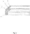
- Figure 4 shows the sealing element 2 in detail.
- the sealing element 2 has an integrated spring element 12 in the form of an annular helical spring.
- the spring element 12 causes the sealing element 2 to be pressed radially into the recess 10.
Landscapes
- Engineering & Computer Science (AREA)
- General Engineering & Computer Science (AREA)
- Mechanical Engineering (AREA)
- Sealing Of Bearings (AREA)
- Sliding-Contact Bearings (AREA)
- Sealing With Elastic Sealing Lips (AREA)
Abstract
Description
- Die Erfindung betrifft eine Lagerbuchse, umfassend zumindest ein Dichtelement und ein Lagerelement, wobei das Dichtelement mit zumindest einer Dichtlippe versehen ist, wobei das Lagerelement im Wesentlichen rohrförmig ausgebildet ist.
- Derartige Lagerbuchsen werden häufig zur Lagerung von Lenkstangen in Fahrzeugen verwendet. Das in die Lagerbuchse integrierte Dichtelement liegt dabei elastisch und mit radialer Vorspannung an der Lenkstange an und verhindert, dass Schmutz oder Feuchtigkeit in die Lagerbuchse eindringen kann.
- Die Lagerbuchse muss dabei so ausgebildet sein, dass diese Querkräfte mit zu vernachlässigender Verformung und geringer Exzentrizität aufnehmen kann.
- Bei der Montage der Lagerbuchse, beziehungsweise der Lenkstange, ist problematisch, dass Fertigungstoleranzen zu einer großen Schwankung der erforderlichen Montagekraft führen können. Dies gilt insbesondere dann, wenn wesentliche Bestandteile der Lagerbuchse aus Kunststoff ausgebildet sind.
- Grundsätzlich ist es denkbar, die zu montierenden Bauteile durch Wärmezufuhr oder Wärmeabfuhr in den Abmessungen so zu verändern, dass eine Montage mit geringerer Kraft möglich ist. Dies erhöht jedoch den Aufwand der Montage. Alternativ ist es möglich, den Außenumfang des zu lagernden Maschinenelementes mit einer elastomeren Beschichtung zu versehen, welche aufgrund der Verformbarkeit Toleranzen kompensieren kann. Hierbei ist problematisch, dass sich durch die Verformung der Elastomerschicht aber bei einer aufzunehmenden Querlast eine erhöhte Exzentrizität ergibt.
- Des Weiteren ist es denkbar, den Außendurchmesser des Lagers mit Rippen zu versehen. Bei dünnwandigen Lagerbuchsen geht dies aber mit einer großen Verformung der Bohrung der Lagerbuchse, also mit einem sich verändernden Innendurchmessers einher. Hieraus kann ein zu großes Spiel zwischen der Lagerbuchse und dem zu lagerndem Maschinenelement resultieren.
- Der Erfindung liegt die Aufgabe zugrunde, eine Lagerbuchse bereitzustellen, welche bei einfacher Montierbarkeit während des Betriebs eine hohe Querbelastung kompensieren kann.
- Diese Aufgabe wird mit den Merkmalen von Anspruch 1 gelöst. Auf vorteilhafte Ausgestaltungen nehmen die Unteransprüche Bezug.
- Die erfindungsgemäße Lagerbuchse umfasst zumindest ein Dichtelement und ein Lagerelement, wobei das Dichtelement mit zumindest einer Dichtlippe versehen ist, wobei das Lagerelement im Wesentlichen rohrförmig ausgebildet ist, wobei das Lagerelement außenumfangsseitig mehrere in Axialrichtung verlaufende Erhebungen aufweist, wobei der Innendurchmesser des Lagerelementes in den den Erhebungen zugeordneten Abschnitten größer ist als in den übrigen Abschnitten.
- Durch die erfindungsgemäße Ausgestaltung kann sich die Lagerbuchse während der Montage in eine Aufnahmebohrung verformen, wodurch die Montagekräfte sinken. Dadurch, dass der Innendurchmesser des Lagerelementes in den den Erhebungen zugeordneten Abschnitten größer ist als in den übrigen Abschnitten, wird die Verformung des Lagerelementes derart kompensiert, dass ein in dem Lagerelement zu lagerndes Maschinenelement mit einem geringen Lagerspiel gelagert werden kann und sich im Lastfall keine unzulässig hohe Exzentrizität ergibt.
- Das Lagerelement ist dabei vorzugsweise so ausgebildet, dass dieses dünnwandig ist. Dünnwandig ist ein Lagerelement im Sinne der Erfindung, wenn die Wandstärke des Lagerelementes acht- bis zwölfmal kleiner ist als der Außendurchmesser des Lagerelementes. Beispielsweise beträgt bei einem Außendurchmesser des Lagerelementes von 25 mm der Innendurchmesser des Lagerelementes, also der Durchmesser der Bohrung des Lagerelementes, 20 mm. Bei einem derartigen Lagerelement ergibt sich eine Wandstärke von 2,5 mm, wenn die Wandstärke des Lagerelementes zehnmal kleiner ist als dessen Außendurchmesser. Wird ein derartiges Lagerelement in eine Aufnahmebohrung eingepresst, so verformt sich das Lagerelement derart, dass sich nach der Montage ein Innendurchmesser mit einer nur sehr geringen Exzentrizität ergibt, so dass anschließend ein Maschinenelement, beispielsweise eine Lenkstange mit geringem Lagerspiel aufgenommen werden kann.
- Vorzugsweise ändert sich der Innendurchmesser des Lagerelementes über den Umfang betrachtet stetig. Gemäß einer vorteilhaften Ausgestaltung verändert sich der Innendurchmesser des Lagerelementes in Umfangsrichtung betrachtet sinusförmig. Hierbei ist vorteilhaft, dass sich eine besonders gute Lastverteilung während der Montage der Lagerbuchse ergibt, was wiederum mit einer besonders geringen Exzentrizität des Innendurchmessers des Lagerelementes einhergeht.
- Das Lagerelement kann vier bis zwölf Erhebungen aufweisen. Die Anzahl der Erhebungen hängt dabei insbesondere von dem Außendurchmesser des Lagerelementes ab, wobei das Lagerelement vorzugsweise je mehr Erhebungen aufweist, desto größer der Außendurchmesser ist. Für die Verwendung der Lagerbuchse als Lagerbuchse für eine Lagerung einer Lenkstange ist es besonders vorteilhaft, wenn das Lagerelement sechs bis zehn Erhebungen aufweist.
- Die Höhe der Erhebungen beträgt vorzugsweise jeweils zwischen 0,9% und 1,5% des Außendurchmessers des Lagerelementes. Bei einem Außendurchmesser des Lagerelementes von 25 mm beträgt dementsprechend die Höhe einer Erhebung zwischen 0,225 mm und 0,375 mm. Es hat sich gezeigt, dass ein derartig ausgestaltetes Lagerelement bei den zu erwartenden Toleranzen mit einer geringen Montagekraft montierbar ist und dabei lediglich eine sehr geringe Exzentrizität hinsichtlich des Innendurchmessers aufweist.
- Die Erhebungen erstrecken sich dabei vorzugsweise jeweils über 4% bis 10% des Umfangs des Lagerelementes. Bei einem Außendurchmesser des Lagerelementes von 25 mm erstrecken sich die Erhebungen dabei dementsprechend jeweils über 1 mm bis 2,5 mm des Umfangs des Lagerelementes.
- Die Erhebungen sind vorzugsweise in Form von Rippen ausgebildet. Ein derartig ausgestaltetes Lagerelement ist besonders einfach herstellbar.
- Der Innendurchmesser der Lagerbuchse kann sich ausgehend von einem mittleren Innendurchmesser über den Umfang betrachtet um bis zu 0,2% vergrößern beziehungsweise verringern. Bei einem Innendurchmesser von 20 mm verändert sich der Innendurchmesser dementsprechend um 0,04 mm. Bei einem sinusförmigen Verlauf der Änderung des Innendurchmessers bewegt sich der Innendurchmesser dementsprechend zwischen 19,96 mm und 20,04 mm. Der mittlere Innendurchmesser beträgt 20 mm.
- Das Lagerelement ist vorzugsweise aus Kunststoff ausgebildet. Insbesondere bei der Verwendung der Lagerbuchse als Lagerbuchse für eine Lenkstange ist aufgrund der zu erwartenden Lagerkräfte Kunststoff der bevorzugte Werkstoff. Hierbei ist insbesondere vorteilhaft, dass eine Lagerung schmiermittelfrei erfolgen kann. Des Weiteren sind Lagerbuchsen aus Kunststoff kostengünstig herstellbar. Vorteilhafte Kunststoffe sind dabei Polyamid (PA), insbesondere Polyamid 6.6, Polybutylenterephthalat (PBT) oder Polytetrafluorethylen (PTFE). Ebenso ist die Verwendung von faserverstärkten Kunststoffen denkbar.
- Um zu verhindern, dass Schmutz oder Feuchtigkeit in das Lagerelement eindringt, ist die Lagerbuchse mit einem Dichtelement versehen. Das Dichtelement weist eine Dichtlippe auf, welche nach Montage unter radialer Vorspannung dichtend an dem zu lagernden Maschinenelement anliegt.
- Gemäß einer vorteilhaften Ausgestaltung umfasst das Dichtelement zwei mit axialem Abstand zueinander angeordnete Dichtlippen, welche jeweils nach Montage mit radialer Vorspannung an dem zu lagernden Maschinenelement anliegen. Durch die doppelte Dichtlippe ergibt sich eine besonders gute Dichtwirkung.
- Das Dichtelement ist vorzugsweise aus einem elastomeren Werkstoff ausgebildet, beispielsweise aus Acrylnitril-Butadien-Kautschuk (NBR). Je nach Anwendung ist ferner denkbar, das Dichtelement aus Ethylen-Propylen-Dien-Monomer (EPDM) auszubilden. Weitere denkbare Werkstoffe sind thermoplastische Elastomere.
- Das Dichtelement ist vorzugsweise formschlüssig mit dem Lagerelement verbunden. Dadurch ist es möglich, das Dichtelement und das Lagerelement aus voneinander abweichenden Werkstoffen unabhängig voneinander herzustellen und anschließend zu montieren.
- Dazu kann das Lagerelement an einer Stirnseite im Bereich des Außenumfangs eine Vertiefung aufweisen, wobei der Stirnseite eine Querschnittserweiterung zugeordnet ist. Durch die Querschnittserweiterung kann ein kongruent ausgeformtes Dichtelement verliersicher in der Vertiefung befestigt werden. Zur Verbesserung der Verliersicherheit kann in das Dichtelement ein Federelement, beispielsweise eine Ringwendelfeder, angeordnet sein, welche das Dichtelement an das Lagerelement andrückt.
- Einige der Ausgestaltungen der erfindungsgemäßen Lagerbuchse werden nachfolgend anhand der Figuren näher erläutert. Diese zeigen, jeweils schematisch:
- Fig. 1
- eine Lagerbuchse im Halbschnitt;
- Fig. 2
- im Detail das Lagerelement der Lagerbuchse im Halbschnitt;
- Fig. 3
- im Detail das Lagerelement in der Draufsicht;
- Fig. 4
- im Detail das Dichtelement der Lagerbuchse im Halbschnitt.
-
Figur 1 zeigt eine Lagerbuchse 1 mit einem Dichtelement 2 und einem Lagerelement 3. Das Dichtelement 2 ist mit zwei parallelen und mit axialem Abstand zueinander angeordneten Dichtlippen 4 versehen, welche axial von der Lagerbuchse 1 abragen und sich radial nach innen erstrecken. - Das Lagerelement 3 ist rohrförmig ausgebildet und mit einer Bohrung 13 zur Aufnahme eines zu lagernden Maschinenelementes versehen.
- Bei der vorliegenden Ausgestaltung ist das Dichtelement 2 aus NBR ausgebildet und das Lagerelement 3 aus Polyamid 6.6. Sowohl das Dichtelement 2 als auch das Lagerelement 3 sind Spritzgussteile.
- Bei der vorliegenden Ausgestaltung dient die Lagerbuchse 1 der Lagerung einer Lenkstange eines Kraftfahrzeuges. Gemäß einer alternativen Ausgestaltung dient die Lagerbuchse 1 der Lagerung von Elementen von Federgabeln von Zweirädern.
-
Figur 2 zeigt im Detail das Lagerelement 3 gemäßFigur 1 . Das Lagerelement 3 weist außenumfangsseitig mehrere in Axialrichtung verlaufende Erhebungen 5 auf. Des Weiteren ist der Innendurchmesser 6 des Lagerelementes 3 in den den Erhebungen 5 zugeordneten Abschnitten größer als in den übrigen Abschnitten. - Das Lagerelement 3 weist an einer Stirnseite 9 eine umlaufende Vertiefung 10 auf, an welche sich in Richtung der Stirnseite 9 eine Querschnittserweiterung 11 anschließt. Die Vertiefung 10 nimmt das Dichtelement 2 auf, wobei das Dichtelement 2 durch die Querschnittserweiterung 11 formschlüssig auf dem Lagerelement 3 fixiert ist.
-
Figur 3 zeigt das Lagerelement 3 in der Draufsicht. In der vorliegenden Ausgestaltung weist das Lagerelement 3 außenumfangsseitig sechs Erhebungen 5 auf. Die Höhe der Erhebung 5 beträgt dabei jeweils 1,2% des Außendurchmessers 8 des Lagerelementes 3. Ferner erstrecken sich die Erhebungen 5 über 8% des Umfangs des Lagerelementes 3. -
Figur 3 kann ferner entnommen werden, dass sich der Innendurchmesser 6 des Lagerelementes 3 über den Umfang betrachtet stetig ändert. Bei der vorliegenden Ausgestaltung ändert sich der Innendurchmesser 6 des Lagerelementes 3 in Umfangsrichtung betrachtet sinusförmig. - Der Innendurchmesser 6 der Lagerbuchse 3 verringert beziehungsweise vergrößert sich ausgehend von einem mittleren Innendurchmesser 6' über den Umfang betrachtet um 0,1%. Daraus resultiert ein größter Innendurchmesser 6", welcher den Erhebungen 5 zugeordnet ist und welcher 0,2% größer ist als der mittlere Durchmesser 6'. Zwischen den Erhebungen 5 ergibt sich ein kleinster Innendurchmesser 6"', welcher 0,2% kleiner ist als der mittlere Innendurchmesser 6'.
- Die Wandstärke 7 des Lagerelementes 3 beträgt 18% des Außendurchmessers 8 des Lagerelementes 3.
- Die Erhebungen 5 sind in Form von Rippen ausgebildet.
-
Figur 4 zeigt im Detail das Dichtelement 2. In dem der Vertiefung 10 zugeordneten Abschnitt des Dichtelementes 2 weist das Dichtelement 2 ein integriertes Federelement 12 in Form einer Ringwendelfeder auf. Das Federelement 12 bewirkt eine radiale Anpressung des Dichtelementes 2 in die Vertiefung 10.
Claims (10)
- Lagerbuchse (1), umfassend zumindest ein Dichtelement (2) und ein Lagerelement (3), wobei das Dichtelement (2) mit zumindest einer Dichtlippe (4) versehen ist, wobei das Lagerelement (3) im Wesentlichen rohrförmig ausgebildet ist, dadurch gekennzeichnet, dass das Lagerelement (3) außenumfangsseitig mehrere in Axialrichtung verlaufende Erhebungen (5) aufweist, wobei der Innendurchmesser (6) des Lagerelementes (3) in den den Erhebungen (5) zugeordneten Abschnitten größer ist als in den übrigen Abschnitten.
- Lagerbuchse nach Anspruch 1, dadurch gekennzeichnet, dass die Wandstärke (7) des Lagerelementes (3) acht- bis zwölfmal kleiner ist als der Außendurchmessers (8) des Lagerelementes (3).
- Lagerbuchse nach Anspruch 1 oder 2, dadurch gekennzeichnet, dass sich der Innendurchmesser (6) des Lagerelementes (3) über den Umfang betrachtet stetig ändert.
- Lagerbuchse nach einem der Ansprüche 1 bis 3, dadurch gekennzeichnet, dass sich der Innendurchmesser (6) des Lagerelementes (3) in Umfangsrichtung betrachtet sinusförmig verändert.
- Lagerbuchse nach einem der Ansprüche 1 bis 4, dadurch gekennzeichnet, dass das Lagerelement (3) vier bis zwölf Erhebungen (5) aufweist.
- Lagerbuchse nach einem der Ansprüche 1 bis 5, dadurch gekennzeichnet, dass die Höhe der Erhebungen (5) jeweils zwischen 0,9% und 1,5% des Außendurchmessers (8) des Lagerelementes (3) entspricht.
- Lagerbuchse nach einem der Ansprüche 1 bis 6, dadurch gekennzeichnet, dass sich die Erhebungen (5) jeweils über 4% bis 10% des Umfangs des Lagerelementes (3) erstrecken.
- Lagerbuchse nach einem der Ansprüche 1 bis 7, dadurch gekennzeichnet, dass die Erhebungen (5) in Form von Rippen ausgebildet sind.
- Lagerbuchse nach einem der Ansprüche 1 bis 8, dadurch gekennzeichnet, dass sich der Innendurchmesser (6) der Lagerbuchse (3) ausgehend von einem mittleren Innendurchmesser (6') über den Umfang betrachtet um bis zu 0,2% vergrößert beziehungsweise verringert.
- Lagerbuchse nach einem der Ansprüche 1 bis 9, dadurch gekennzeichnet, dass das Lagerelement (3) aus Kunststoff ausgebildet ist.
Applications Claiming Priority (1)
| Application Number | Priority Date | Filing Date | Title |
|---|---|---|---|
| DE102019105112.6A DE102019105112A1 (de) | 2019-02-28 | 2019-02-28 | Lagerbuchse |
Publications (3)
| Publication Number | Publication Date |
|---|---|
| EP3702631A2 true EP3702631A2 (de) | 2020-09-02 |
| EP3702631A3 EP3702631A3 (de) | 2020-09-23 |
| EP3702631B1 EP3702631B1 (de) | 2022-03-30 |
Family
ID=69528670
Family Applications (1)
| Application Number | Title | Priority Date | Filing Date |
|---|---|---|---|
| EP20156273.3A Active EP3702631B1 (de) | 2019-02-28 | 2020-02-10 | Lagerbuchse |
Country Status (4)
| Country | Link |
|---|---|
| US (1) | US11078963B2 (de) |
| EP (1) | EP3702631B1 (de) |
| DE (1) | DE102019105112A1 (de) |
| MX (1) | MX2020002252A (de) |
Families Citing this family (1)
| Publication number | Priority date | Publication date | Assignee | Title |
|---|---|---|---|---|
| US20250012327A1 (en) * | 2023-07-03 | 2025-01-09 | Hanon Systems | Combination seal and bearing |
Family Cites Families (12)
| Publication number | Priority date | Publication date | Assignee | Title |
|---|---|---|---|---|
| FR1310614A (fr) * | 1961-10-17 | 1962-11-30 | Coussinet perfectionné | |
| DE1400967A1 (de) | 1963-01-18 | 1968-11-21 | Continental Gummi Werke Ag | Lagerbuchse aus gummielastischen Werkstoffen |
| DE3412562A1 (de) * | 1983-05-14 | 1984-11-15 | Gerhard 3012 Langenhagen Lorenz | Vorrichtung zum abdichten von lagern, insbesondere von gekapselten, wartungsfreien lagern |
| FR2674918B1 (fr) * | 1991-04-05 | 1995-05-19 | Ardepa | Palier coulissant. |
| DE4239938C1 (de) * | 1992-11-27 | 1994-04-21 | Glyco Metall Werke | Gerollte Lagerbuchse |
| DE4401526C1 (de) * | 1994-01-20 | 1994-12-15 | Wieland Werke Ag | Gleitlager mit integrierter Lippendichtung |
| DE4435098A1 (de) | 1994-09-30 | 1996-04-04 | Kolbenschmidt Ag | Gerollte Buchse für Gleitlager |
| GB0018904D0 (en) * | 2000-08-03 | 2000-09-20 | Dana Corp | Bearings |
| DE10312873A1 (de) * | 2003-03-22 | 2004-10-07 | Gkn Sinter Metals Gmbh | Sintergleitlager mit kontinuierlicher Variation der Bohrungsverdichtung |
| DE102007034536A1 (de) * | 2007-07-25 | 2009-02-05 | Ab Skf | Gleitlagerbuchse |
| DE102007053902A1 (de) | 2007-11-09 | 2009-05-20 | Knorr-Bremse Systeme für Nutzfahrzeuge GmbH | Scheibenbremse für ein Nutzfahrzeug |
| DE102014000197A1 (de) * | 2014-01-14 | 2015-07-16 | Schwing Gmbh | Lagerung einer drehenden Welle mit Dichtring |
-
2019
- 2019-02-28 DE DE102019105112.6A patent/DE102019105112A1/de not_active Ceased
-
2020
- 2020-02-10 EP EP20156273.3A patent/EP3702631B1/de active Active
- 2020-02-24 US US16/798,488 patent/US11078963B2/en active Active
- 2020-02-27 MX MX2020002252A patent/MX2020002252A/es unknown
Also Published As
| Publication number | Publication date |
|---|---|
| DE102019105112A1 (de) | 2020-09-03 |
| US11078963B2 (en) | 2021-08-03 |
| US20200277992A1 (en) | 2020-09-03 |
| EP3702631A3 (de) | 2020-09-23 |
| EP3702631B1 (de) | 2022-03-30 |
| MX2020002252A (es) | 2020-09-01 |
Similar Documents
| Publication | Publication Date | Title |
|---|---|---|
| DE102012207527B4 (de) | Hülsengelenk für ein Fahrzeug | |
| WO2008068179A2 (de) | Federbeinlager | |
| DE10246354B4 (de) | Gleichlaufgelenkmanschette | |
| EP1325245A1 (de) | Schwingungsgedämpftes gummilager | |
| DE102006021011B4 (de) | Buchsenlager mit axialseitig profiliertem Lagerkörper | |
| EP3006765A1 (de) | Elastomerlager als buchsenlager | |
| EP1132642B1 (de) | Gummilager | |
| DE102016012538B4 (de) | Gummilager und Verfahren zum Herstellen eines Gummilagers | |
| EP3842296B1 (de) | Schwingungstilgerring sowie gassackmodul mit einem solchen schwingungstilgerring | |
| WO2011160877A1 (de) | Federbeinlager und herstellungsverfahren für ein reibungsreduzierendes bauteil eines federbeinlagers | |
| DE102018106365B4 (de) | Lageranordnung | |
| EP3702631B1 (de) | Lagerbuchse | |
| EP1691104B1 (de) | Elastisches Lager | |
| DE102015220151A1 (de) | Lageranordnung und Dichtung | |
| WO2021197685A1 (de) | Schwingungsdämpfendes entkopplungselement | |
| DE102017209890A1 (de) | Kugelgelenk für einen Zweipunktlenker sowie Zweipunktlenker mit einem solchen Kugelgelenk | |
| DE102018121219A1 (de) | Lagerbuchse für ein Sackloch und Lenkgetriebeaufhängung für ein Fahrzeug | |
| DE102018208298A1 (de) | Koppelstange, Radaufhängung und Verfahren zur Herstellung einer Koppelstange | |
| DE102017111996B4 (de) | Lageranordnung | |
| DE102021108720B4 (de) | Selbsthemmendes Buchsenlager | |
| DE102016217300B4 (de) | Federbeinlager | |
| EP1747384B1 (de) | Lageranordnung bestehend aus einem lager und einem lagerträger | |
| DE102017219309B4 (de) | Aktuator einer Lenkung mit einem Spindelantrieb sowie Verfahren zur Montage eines Spindelantriebs | |
| DE202021103783U1 (de) | Elastomer-Metall-Lager | |
| WO2022073531A1 (de) | Käfig für wälzlager, wälzlager mit käfig und montageverfahren für wälzlager |
Legal Events
| Date | Code | Title | Description |
|---|---|---|---|
| PUAI | Public reference made under article 153(3) epc to a published international application that has entered the european phase |
Free format text: ORIGINAL CODE: 0009012 |
|
| STAA | Information on the status of an ep patent application or granted ep patent |
Free format text: STATUS: THE APPLICATION HAS BEEN PUBLISHED |
|
| PUAL | Search report despatched |
Free format text: ORIGINAL CODE: 0009013 |
|
| AK | Designated contracting states |
Kind code of ref document: A2 Designated state(s): AL AT BE BG CH CY CZ DE DK EE ES FI FR GB GR HR HU IE IS IT LI LT LU LV MC MK MT NL NO PL PT RO RS SE SI SK SM TR |
|
| AX | Request for extension of the european patent |
Extension state: BA ME |
|
| AK | Designated contracting states |
Kind code of ref document: A3 Designated state(s): AL AT BE BG CH CY CZ DE DK EE ES FI FR GB GR HR HU IE IS IT LI LT LU LV MC MK MT NL NO PL PT RO RS SE SI SK SM TR |
|
| AX | Request for extension of the european patent |
Extension state: BA ME |
|
| RIC1 | Information provided on ipc code assigned before grant |
Ipc: F16C 17/02 20060101AFI20200820BHEP Ipc: F16C 33/74 20060101ALI20200820BHEP Ipc: F16C 33/20 20060101ALI20200820BHEP |
|
| STAA | Information on the status of an ep patent application or granted ep patent |
Free format text: STATUS: REQUEST FOR EXAMINATION WAS MADE |
|
| 17P | Request for examination filed |
Effective date: 20210128 |
|
| RBV | Designated contracting states (corrected) |
Designated state(s): AL AT BE BG CH CY CZ DE DK EE ES FI FR GB GR HR HU IE IS IT LI LT LU LV MC MK MT NL NO PL PT RO RS SE SI SK SM TR |
|
| REG | Reference to a national code |
Ref country code: DE Ref legal event code: R079 Ref document number: 502020000849 Country of ref document: DE Free format text: PREVIOUS MAIN CLASS: F16C0017020000 Ipc: F16C0029080000 |
|
| GRAP | Despatch of communication of intention to grant a patent |
Free format text: ORIGINAL CODE: EPIDOSNIGR1 |
|
| STAA | Information on the status of an ep patent application or granted ep patent |
Free format text: STATUS: GRANT OF PATENT IS INTENDED |
|
| RIC1 | Information provided on ipc code assigned before grant |
Ipc: F16C 29/02 20060101ALI20210913BHEP Ipc: F16C 29/08 20060101AFI20210913BHEP |
|
| INTG | Intention to grant announced |
Effective date: 20211005 |
|
| GRAS | Grant fee paid |
Free format text: ORIGINAL CODE: EPIDOSNIGR3 |
|
| GRAA | (expected) grant |
Free format text: ORIGINAL CODE: 0009210 |
|
| STAA | Information on the status of an ep patent application or granted ep patent |
Free format text: STATUS: THE PATENT HAS BEEN GRANTED |
|
| AK | Designated contracting states |
Kind code of ref document: B1 Designated state(s): AL AT BE BG CH CY CZ DE DK EE ES FI FR GB GR HR HU IE IS IT LI LT LU LV MC MK MT NL NO PL PT RO RS SE SI SK SM TR |
|
| REG | Reference to a national code |
Ref country code: GB Ref legal event code: FG4D Free format text: NOT ENGLISH |
|
| REG | Reference to a national code |
Ref country code: CH Ref legal event code: EP |
|
| REG | Reference to a national code |
Ref country code: AT Ref legal event code: REF Ref document number: 1479451 Country of ref document: AT Kind code of ref document: T Effective date: 20220415 |
|
| REG | Reference to a national code |
Ref country code: DE Ref legal event code: R096 Ref document number: 502020000849 Country of ref document: DE |
|
| REG | Reference to a national code |
Ref country code: IE Ref legal event code: FG4D Free format text: LANGUAGE OF EP DOCUMENT: GERMAN |
|
| REG | Reference to a national code |
Ref country code: LT Ref legal event code: MG9D |
|
| PG25 | Lapsed in a contracting state [announced via postgrant information from national office to epo] |
Ref country code: SE Free format text: LAPSE BECAUSE OF FAILURE TO SUBMIT A TRANSLATION OF THE DESCRIPTION OR TO PAY THE FEE WITHIN THE PRESCRIBED TIME-LIMIT Effective date: 20220330 Ref country code: RS Free format text: LAPSE BECAUSE OF FAILURE TO SUBMIT A TRANSLATION OF THE DESCRIPTION OR TO PAY THE FEE WITHIN THE PRESCRIBED TIME-LIMIT Effective date: 20220330 Ref country code: NO Free format text: LAPSE BECAUSE OF FAILURE TO SUBMIT A TRANSLATION OF THE DESCRIPTION OR TO PAY THE FEE WITHIN THE PRESCRIBED TIME-LIMIT Effective date: 20220630 Ref country code: LT Free format text: LAPSE BECAUSE OF FAILURE TO SUBMIT A TRANSLATION OF THE DESCRIPTION OR TO PAY THE FEE WITHIN THE PRESCRIBED TIME-LIMIT Effective date: 20220330 Ref country code: HR Free format text: LAPSE BECAUSE OF FAILURE TO SUBMIT A TRANSLATION OF THE DESCRIPTION OR TO PAY THE FEE WITHIN THE PRESCRIBED TIME-LIMIT Effective date: 20220330 Ref country code: BG Free format text: LAPSE BECAUSE OF FAILURE TO SUBMIT A TRANSLATION OF THE DESCRIPTION OR TO PAY THE FEE WITHIN THE PRESCRIBED TIME-LIMIT Effective date: 20220630 |
|
| REG | Reference to a national code |
Ref country code: NL Ref legal event code: MP Effective date: 20220330 |
|
| PG25 | Lapsed in a contracting state [announced via postgrant information from national office to epo] |
Ref country code: LV Free format text: LAPSE BECAUSE OF FAILURE TO SUBMIT A TRANSLATION OF THE DESCRIPTION OR TO PAY THE FEE WITHIN THE PRESCRIBED TIME-LIMIT Effective date: 20220330 Ref country code: GR Free format text: LAPSE BECAUSE OF FAILURE TO SUBMIT A TRANSLATION OF THE DESCRIPTION OR TO PAY THE FEE WITHIN THE PRESCRIBED TIME-LIMIT Effective date: 20220701 Ref country code: FI Free format text: LAPSE BECAUSE OF FAILURE TO SUBMIT A TRANSLATION OF THE DESCRIPTION OR TO PAY THE FEE WITHIN THE PRESCRIBED TIME-LIMIT Effective date: 20220330 |
|
| PG25 | Lapsed in a contracting state [announced via postgrant information from national office to epo] |
Ref country code: NL Free format text: LAPSE BECAUSE OF FAILURE TO SUBMIT A TRANSLATION OF THE DESCRIPTION OR TO PAY THE FEE WITHIN THE PRESCRIBED TIME-LIMIT Effective date: 20220330 |
|
| PG25 | Lapsed in a contracting state [announced via postgrant information from national office to epo] |
Ref country code: SM Free format text: LAPSE BECAUSE OF FAILURE TO SUBMIT A TRANSLATION OF THE DESCRIPTION OR TO PAY THE FEE WITHIN THE PRESCRIBED TIME-LIMIT Effective date: 20220330 Ref country code: SK Free format text: LAPSE BECAUSE OF FAILURE TO SUBMIT A TRANSLATION OF THE DESCRIPTION OR TO PAY THE FEE WITHIN THE PRESCRIBED TIME-LIMIT Effective date: 20220330 Ref country code: RO Free format text: LAPSE BECAUSE OF FAILURE TO SUBMIT A TRANSLATION OF THE DESCRIPTION OR TO PAY THE FEE WITHIN THE PRESCRIBED TIME-LIMIT Effective date: 20220330 Ref country code: PT Free format text: LAPSE BECAUSE OF FAILURE TO SUBMIT A TRANSLATION OF THE DESCRIPTION OR TO PAY THE FEE WITHIN THE PRESCRIBED TIME-LIMIT Effective date: 20220801 Ref country code: ES Free format text: LAPSE BECAUSE OF FAILURE TO SUBMIT A TRANSLATION OF THE DESCRIPTION OR TO PAY THE FEE WITHIN THE PRESCRIBED TIME-LIMIT Effective date: 20220330 Ref country code: EE Free format text: LAPSE BECAUSE OF FAILURE TO SUBMIT A TRANSLATION OF THE DESCRIPTION OR TO PAY THE FEE WITHIN THE PRESCRIBED TIME-LIMIT Effective date: 20220330 Ref country code: CZ Free format text: LAPSE BECAUSE OF FAILURE TO SUBMIT A TRANSLATION OF THE DESCRIPTION OR TO PAY THE FEE WITHIN THE PRESCRIBED TIME-LIMIT Effective date: 20220330 |
|
| PG25 | Lapsed in a contracting state [announced via postgrant information from national office to epo] |
Ref country code: PL Free format text: LAPSE BECAUSE OF FAILURE TO SUBMIT A TRANSLATION OF THE DESCRIPTION OR TO PAY THE FEE WITHIN THE PRESCRIBED TIME-LIMIT Effective date: 20220330 Ref country code: IS Free format text: LAPSE BECAUSE OF FAILURE TO SUBMIT A TRANSLATION OF THE DESCRIPTION OR TO PAY THE FEE WITHIN THE PRESCRIBED TIME-LIMIT Effective date: 20220730 Ref country code: AL Free format text: LAPSE BECAUSE OF FAILURE TO SUBMIT A TRANSLATION OF THE DESCRIPTION OR TO PAY THE FEE WITHIN THE PRESCRIBED TIME-LIMIT Effective date: 20220330 |
|
| REG | Reference to a national code |
Ref country code: DE Ref legal event code: R097 Ref document number: 502020000849 Country of ref document: DE |
|
| PG25 | Lapsed in a contracting state [announced via postgrant information from national office to epo] |
Ref country code: DK Free format text: LAPSE BECAUSE OF FAILURE TO SUBMIT A TRANSLATION OF THE DESCRIPTION OR TO PAY THE FEE WITHIN THE PRESCRIBED TIME-LIMIT Effective date: 20220330 |
|
| PLBE | No opposition filed within time limit |
Free format text: ORIGINAL CODE: 0009261 |
|
| STAA | Information on the status of an ep patent application or granted ep patent |
Free format text: STATUS: NO OPPOSITION FILED WITHIN TIME LIMIT |
|
| 26N | No opposition filed |
Effective date: 20230103 |
|
| PG25 | Lapsed in a contracting state [announced via postgrant information from national office to epo] |
Ref country code: SI Free format text: LAPSE BECAUSE OF FAILURE TO SUBMIT A TRANSLATION OF THE DESCRIPTION OR TO PAY THE FEE WITHIN THE PRESCRIBED TIME-LIMIT Effective date: 20220330 |
|
| PG25 | Lapsed in a contracting state [announced via postgrant information from national office to epo] |
Ref country code: IT Free format text: LAPSE BECAUSE OF FAILURE TO SUBMIT A TRANSLATION OF THE DESCRIPTION OR TO PAY THE FEE WITHIN THE PRESCRIBED TIME-LIMIT Effective date: 20220330 |
|
| PG25 | Lapsed in a contracting state [announced via postgrant information from national office to epo] |
Ref country code: MC Free format text: LAPSE BECAUSE OF FAILURE TO SUBMIT A TRANSLATION OF THE DESCRIPTION OR TO PAY THE FEE WITHIN THE PRESCRIBED TIME-LIMIT Effective date: 20220330 |
|
| REG | Reference to a national code |
Ref country code: CH Ref legal event code: PL |
|
| REG | Reference to a national code |
Ref country code: BE Ref legal event code: MM Effective date: 20230228 |
|
| PG25 | Lapsed in a contracting state [announced via postgrant information from national office to epo] |
Ref country code: LU Free format text: LAPSE BECAUSE OF NON-PAYMENT OF DUE FEES Effective date: 20230210 Ref country code: LI Free format text: LAPSE BECAUSE OF NON-PAYMENT OF DUE FEES Effective date: 20230228 Ref country code: CH Free format text: LAPSE BECAUSE OF NON-PAYMENT OF DUE FEES Effective date: 20230228 |
|
| REG | Reference to a national code |
Ref country code: IE Ref legal event code: MM4A |
|
| PG25 | Lapsed in a contracting state [announced via postgrant information from national office to epo] |
Ref country code: IE Free format text: LAPSE BECAUSE OF NON-PAYMENT OF DUE FEES Effective date: 20230210 Ref country code: FR Free format text: LAPSE BECAUSE OF NON-PAYMENT OF DUE FEES Effective date: 20230228 |
|
| PG25 | Lapsed in a contracting state [announced via postgrant information from national office to epo] |
Ref country code: BE Free format text: LAPSE BECAUSE OF NON-PAYMENT OF DUE FEES Effective date: 20230228 |
|
| GBPC | Gb: european patent ceased through non-payment of renewal fee |
Effective date: 20240210 |
|
| PG25 | Lapsed in a contracting state [announced via postgrant information from national office to epo] |
Ref country code: GB Free format text: LAPSE BECAUSE OF NON-PAYMENT OF DUE FEES Effective date: 20240210 |
|
| PG25 | Lapsed in a contracting state [announced via postgrant information from national office to epo] |
Ref country code: GB Free format text: LAPSE BECAUSE OF NON-PAYMENT OF DUE FEES Effective date: 20240210 |
|
| PGFP | Annual fee paid to national office [announced via postgrant information from national office to epo] |
Ref country code: AT Payment date: 20250417 Year of fee payment: 5 |
|
| PG25 | Lapsed in a contracting state [announced via postgrant information from national office to epo] |
Ref country code: CY Free format text: LAPSE BECAUSE OF FAILURE TO SUBMIT A TRANSLATION OF THE DESCRIPTION OR TO PAY THE FEE WITHIN THE PRESCRIBED TIME-LIMIT; INVALID AB INITIO Effective date: 20200210 |
|
| PG25 | Lapsed in a contracting state [announced via postgrant information from national office to epo] |
Ref country code: HU Free format text: LAPSE BECAUSE OF FAILURE TO SUBMIT A TRANSLATION OF THE DESCRIPTION OR TO PAY THE FEE WITHIN THE PRESCRIBED TIME-LIMIT; INVALID AB INITIO Effective date: 20200210 |
|
| PG25 | Lapsed in a contracting state [announced via postgrant information from national office to epo] |
Ref country code: TR Free format text: LAPSE BECAUSE OF FAILURE TO SUBMIT A TRANSLATION OF THE DESCRIPTION OR TO PAY THE FEE WITHIN THE PRESCRIBED TIME-LIMIT Effective date: 20220330 |
|
| PGFP | Annual fee paid to national office [announced via postgrant information from national office to epo] |
Ref country code: DE Payment date: 20260220 Year of fee payment: 7 |
|
| PG25 | Lapsed in a contracting state [announced via postgrant information from national office to epo] |
Ref country code: AT Free format text: LAPSE BECAUSE OF NON-PAYMENT OF DUE FEES Effective date: 20250210 |
|
| REG | Reference to a national code |
Ref country code: AT Ref legal event code: MM01 Ref document number: 1479451 Country of ref document: AT Kind code of ref document: T Effective date: 20250210 |