EP3702602A1 - Systems and methods for automatically monitoring and controlling temperature for a vehicle - Google Patents
Systems and methods for automatically monitoring and controlling temperature for a vehicle Download PDFInfo
- Publication number
- EP3702602A1 EP3702602A1 EP20169871.9A EP20169871A EP3702602A1 EP 3702602 A1 EP3702602 A1 EP 3702602A1 EP 20169871 A EP20169871 A EP 20169871A EP 3702602 A1 EP3702602 A1 EP 3702602A1
- Authority
- EP
- European Patent Office
- Prior art keywords
- temperature
- interval time
- vehicle
- threshold
- value
- Prior art date
- Legal status (The legal status is an assumption and is not a legal conclusion. Google has not performed a legal analysis and makes no representation as to the accuracy of the status listed.)
- Granted
Links
Images


Classifications
-
- F—MECHANICAL ENGINEERING; LIGHTING; HEATING; WEAPONS; BLASTING
- F02—COMBUSTION ENGINES; HOT-GAS OR COMBUSTION-PRODUCT ENGINE PLANTS
- F02N—STARTING OF COMBUSTION ENGINES; STARTING AIDS FOR SUCH ENGINES, NOT OTHERWISE PROVIDED FOR
- F02N11/00—Starting of engines by means of electric motors
- F02N11/08—Circuits specially adapted for starting of engines
- F02N11/0803—Circuits specially adapted for starting of engines characterised by means for initiating engine start or stop
-
- F—MECHANICAL ENGINEERING; LIGHTING; HEATING; WEAPONS; BLASTING
- F01—MACHINES OR ENGINES IN GENERAL; ENGINE PLANTS IN GENERAL; STEAM ENGINES
- F01P—COOLING OF MACHINES OR ENGINES IN GENERAL; COOLING OF INTERNAL-COMBUSTION ENGINES
- F01P11/00—Component parts, details, or accessories not provided for in, or of interest apart from, groups F01P1/00 - F01P9/00
- F01P11/14—Indicating devices; Other safety devices
- F01P11/20—Indicating devices; Other safety devices concerning atmospheric freezing conditions, e.g. automatically draining or heating during frosty weather
-
- F—MECHANICAL ENGINEERING; LIGHTING; HEATING; WEAPONS; BLASTING
- F02—COMBUSTION ENGINES; HOT-GAS OR COMBUSTION-PRODUCT ENGINE PLANTS
- F02B—INTERNAL-COMBUSTION PISTON ENGINES; COMBUSTION ENGINES IN GENERAL
- F02B3/00—Engines characterised by air compression and subsequent fuel addition
- F02B3/06—Engines characterised by air compression and subsequent fuel addition with compression ignition
-
- F—MECHANICAL ENGINEERING; LIGHTING; HEATING; WEAPONS; BLASTING
- F02—COMBUSTION ENGINES; HOT-GAS OR COMBUSTION-PRODUCT ENGINE PLANTS
- F02D—CONTROLLING COMBUSTION ENGINES
- F02D41/00—Electrical control of supply of combustible mixture or its constituents
- F02D41/02—Circuit arrangements for generating control signals
- F02D41/04—Introducing corrections for particular operating conditions
- F02D41/042—Introducing corrections for particular operating conditions for stopping the engine
-
- F—MECHANICAL ENGINEERING; LIGHTING; HEATING; WEAPONS; BLASTING
- F02—COMBUSTION ENGINES; HOT-GAS OR COMBUSTION-PRODUCT ENGINE PLANTS
- F02D—CONTROLLING COMBUSTION ENGINES
- F02D41/00—Electrical control of supply of combustible mixture or its constituents
- F02D41/02—Circuit arrangements for generating control signals
- F02D41/04—Introducing corrections for particular operating conditions
- F02D41/06—Introducing corrections for particular operating conditions for engine starting or warming up
- F02D41/062—Introducing corrections for particular operating conditions for engine starting or warming up for starting
- F02D41/064—Introducing corrections for particular operating conditions for engine starting or warming up for starting at cold start
-
- F—MECHANICAL ENGINEERING; LIGHTING; HEATING; WEAPONS; BLASTING
- F02—COMBUSTION ENGINES; HOT-GAS OR COMBUSTION-PRODUCT ENGINE PLANTS
- F02D—CONTROLLING COMBUSTION ENGINES
- F02D41/00—Electrical control of supply of combustible mixture or its constituents
- F02D41/02—Circuit arrangements for generating control signals
- F02D41/04—Introducing corrections for particular operating conditions
- F02D41/06—Introducing corrections for particular operating conditions for engine starting or warming up
- F02D41/068—Introducing corrections for particular operating conditions for engine starting or warming up for warming-up
-
- F—MECHANICAL ENGINEERING; LIGHTING; HEATING; WEAPONS; BLASTING
- F02—COMBUSTION ENGINES; HOT-GAS OR COMBUSTION-PRODUCT ENGINE PLANTS
- F02N—STARTING OF COMBUSTION ENGINES; STARTING AIDS FOR SUCH ENGINES, NOT OTHERWISE PROVIDED FOR
- F02N11/00—Starting of engines by means of electric motors
- F02N11/08—Circuits specially adapted for starting of engines
- F02N11/0803—Circuits specially adapted for starting of engines characterised by means for initiating engine start or stop
- F02N11/0811—Circuits specially adapted for starting of engines characterised by means for initiating engine start or stop using a timer
-
- F—MECHANICAL ENGINEERING; LIGHTING; HEATING; WEAPONS; BLASTING
- F02—COMBUSTION ENGINES; HOT-GAS OR COMBUSTION-PRODUCT ENGINE PLANTS
- F02N—STARTING OF COMBUSTION ENGINES; STARTING AIDS FOR SUCH ENGINES, NOT OTHERWISE PROVIDED FOR
- F02N11/00—Starting of engines by means of electric motors
- F02N11/08—Circuits specially adapted for starting of engines
- F02N11/0814—Circuits specially adapted for starting of engines comprising means for controlling automatic idle-start-stop
- F02N11/0818—Conditions for starting or stopping the engine or for deactivating the idle-start-stop mode
- F02N11/0825—Conditions for starting or stopping the engine or for deactivating the idle-start-stop mode related to prevention of engine restart failure, e.g. disabling automatic stop at low battery state
-
- F—MECHANICAL ENGINEERING; LIGHTING; HEATING; WEAPONS; BLASTING
- F02—COMBUSTION ENGINES; HOT-GAS OR COMBUSTION-PRODUCT ENGINE PLANTS
- F02N—STARTING OF COMBUSTION ENGINES; STARTING AIDS FOR SUCH ENGINES, NOT OTHERWISE PROVIDED FOR
- F02N11/00—Starting of engines by means of electric motors
- F02N11/08—Circuits specially adapted for starting of engines
- F02N11/0814—Circuits specially adapted for starting of engines comprising means for controlling automatic idle-start-stop
- F02N11/0818—Conditions for starting or stopping the engine or for deactivating the idle-start-stop mode
- F02N11/0829—Conditions for starting or stopping the engine or for deactivating the idle-start-stop mode related to special engine control, e.g. giving priority to engine warming-up or learning
-
- F—MECHANICAL ENGINEERING; LIGHTING; HEATING; WEAPONS; BLASTING
- F02—COMBUSTION ENGINES; HOT-GAS OR COMBUSTION-PRODUCT ENGINE PLANTS
- F02N—STARTING OF COMBUSTION ENGINES; STARTING AIDS FOR SUCH ENGINES, NOT OTHERWISE PROVIDED FOR
- F02N11/00—Starting of engines by means of electric motors
- F02N11/08—Circuits specially adapted for starting of engines
- F02N11/0814—Circuits specially adapted for starting of engines comprising means for controlling automatic idle-start-stop
- F02N11/0818—Conditions for starting or stopping the engine or for deactivating the idle-start-stop mode
- F02N11/0833—Vehicle conditions
-
- F—MECHANICAL ENGINEERING; LIGHTING; HEATING; WEAPONS; BLASTING
- F02—COMBUSTION ENGINES; HOT-GAS OR COMBUSTION-PRODUCT ENGINE PLANTS
- F02N—STARTING OF COMBUSTION ENGINES; STARTING AIDS FOR SUCH ENGINES, NOT OTHERWISE PROVIDED FOR
- F02N19/00—Starting aids for combustion engines, not otherwise provided for
- F02N19/02—Aiding engine start by thermal means, e.g. using lighted wicks
-
- F—MECHANICAL ENGINEERING; LIGHTING; HEATING; WEAPONS; BLASTING
- F02—COMBUSTION ENGINES; HOT-GAS OR COMBUSTION-PRODUCT ENGINE PLANTS
- F02D—CONTROLLING COMBUSTION ENGINES
- F02D2200/00—Input parameters for engine control
- F02D2200/02—Input parameters for engine control the parameters being related to the engine
- F02D2200/023—Temperature of lubricating oil or working fluid
-
- F—MECHANICAL ENGINEERING; LIGHTING; HEATING; WEAPONS; BLASTING
- F02—COMBUSTION ENGINES; HOT-GAS OR COMBUSTION-PRODUCT ENGINE PLANTS
- F02D—CONTROLLING COMBUSTION ENGINES
- F02D2200/00—Input parameters for engine control
- F02D2200/02—Input parameters for engine control the parameters being related to the engine
- F02D2200/06—Fuel or fuel supply system parameters
- F02D2200/0606—Fuel temperature
-
- F—MECHANICAL ENGINEERING; LIGHTING; HEATING; WEAPONS; BLASTING
- F02—COMBUSTION ENGINES; HOT-GAS OR COMBUSTION-PRODUCT ENGINE PLANTS
- F02D—CONTROLLING COMBUSTION ENGINES
- F02D2200/00—Input parameters for engine control
- F02D2200/02—Input parameters for engine control the parameters being related to the engine
- F02D2200/06—Fuel or fuel supply system parameters
- F02D2200/0606—Fuel temperature
- F02D2200/0608—Estimation of fuel temperature
-
- F—MECHANICAL ENGINEERING; LIGHTING; HEATING; WEAPONS; BLASTING
- F02—COMBUSTION ENGINES; HOT-GAS OR COMBUSTION-PRODUCT ENGINE PLANTS
- F02N—STARTING OF COMBUSTION ENGINES; STARTING AIDS FOR SUCH ENGINES, NOT OTHERWISE PROVIDED FOR
- F02N2200/00—Parameters used for control of starting apparatus
- F02N2200/02—Parameters used for control of starting apparatus said parameters being related to the engine
- F02N2200/023—Engine temperature
-
- F—MECHANICAL ENGINEERING; LIGHTING; HEATING; WEAPONS; BLASTING
- F02—COMBUSTION ENGINES; HOT-GAS OR COMBUSTION-PRODUCT ENGINE PLANTS
- F02N—STARTING OF COMBUSTION ENGINES; STARTING AIDS FOR SUCH ENGINES, NOT OTHERWISE PROVIDED FOR
- F02N2200/00—Parameters used for control of starting apparatus
- F02N2200/02—Parameters used for control of starting apparatus said parameters being related to the engine
- F02N2200/024—Engine oil temperature
-
- F—MECHANICAL ENGINEERING; LIGHTING; HEATING; WEAPONS; BLASTING
- F02—COMBUSTION ENGINES; HOT-GAS OR COMBUSTION-PRODUCT ENGINE PLANTS
- F02N—STARTING OF COMBUSTION ENGINES; STARTING AIDS FOR SUCH ENGINES, NOT OTHERWISE PROVIDED FOR
- F02N2200/00—Parameters used for control of starting apparatus
- F02N2200/08—Parameters used for control of starting apparatus said parameters being related to the vehicle or its components
- F02N2200/0804—Temperature inside the vehicle cabin
-
- F—MECHANICAL ENGINEERING; LIGHTING; HEATING; WEAPONS; BLASTING
- F02—COMBUSTION ENGINES; HOT-GAS OR COMBUSTION-PRODUCT ENGINE PLANTS
- F02N—STARTING OF COMBUSTION ENGINES; STARTING AIDS FOR SUCH ENGINES, NOT OTHERWISE PROVIDED FOR
- F02N2200/00—Parameters used for control of starting apparatus
- F02N2200/08—Parameters used for control of starting apparatus said parameters being related to the vehicle or its components
- F02N2200/0811—Heating state
-
- F—MECHANICAL ENGINEERING; LIGHTING; HEATING; WEAPONS; BLASTING
- F02—COMBUSTION ENGINES; HOT-GAS OR COMBUSTION-PRODUCT ENGINE PLANTS
- F02N—STARTING OF COMBUSTION ENGINES; STARTING AIDS FOR SUCH ENGINES, NOT OTHERWISE PROVIDED FOR
- F02N2200/00—Parameters used for control of starting apparatus
- F02N2200/12—Parameters used for control of starting apparatus said parameters being related to the vehicle exterior
- F02N2200/122—Atmospheric temperature
-
- F—MECHANICAL ENGINEERING; LIGHTING; HEATING; WEAPONS; BLASTING
- F02—COMBUSTION ENGINES; HOT-GAS OR COMBUSTION-PRODUCT ENGINE PLANTS
- F02N—STARTING OF COMBUSTION ENGINES; STARTING AIDS FOR SUCH ENGINES, NOT OTHERWISE PROVIDED FOR
- F02N2300/00—Control related aspects of engine starting
- F02N2300/20—Control related aspects of engine starting characterised by the control method
- F02N2300/2011—Control involving a delay; Control involving a waiting period before engine stop or engine start
-
- Y—GENERAL TAGGING OF NEW TECHNOLOGICAL DEVELOPMENTS; GENERAL TAGGING OF CROSS-SECTIONAL TECHNOLOGIES SPANNING OVER SEVERAL SECTIONS OF THE IPC; TECHNICAL SUBJECTS COVERED BY FORMER USPC CROSS-REFERENCE ART COLLECTIONS [XRACs] AND DIGESTS
- Y02—TECHNOLOGIES OR APPLICATIONS FOR MITIGATION OR ADAPTATION AGAINST CLIMATE CHANGE
- Y02T—CLIMATE CHANGE MITIGATION TECHNOLOGIES RELATED TO TRANSPORTATION
- Y02T10/00—Road transport of goods or passengers
- Y02T10/10—Internal combustion engine [ICE] based vehicles
- Y02T10/40—Engine management systems
Definitions
- Prior art document KR20130013176A1 discloses an automatic monitoring and control of the temperature of a vehicle.
- FIGURE 1 is a block diagram that illustrates a controller of a vehicle according to an embodiment of the invention.
- the vehicle 100 uses diesel fuel.
- the vehicle 100 is a Class 8 truck.
- the vehicle 100 may be any type of vehicle for which a minimum temperature must be maintained at all times in order to ensure operability.
- the vehicle 100 includes an engine 110, an oil temperature sensor 112, an air temperature sensor 114, one or more electronic cab components 106, an engine control module (ECM) 108, an ignition bus 104, and a temperature monitoring controller 102.
- ECM engine control module
- a typical vehicle 100 will contain many more components known to one of ordinary skill in the art, but which are not illustrated or described herein for the sake of clarity.
- the engine 110 is an internal combustion engine. In some embodiments, the engine 110 is configured to be powered by a diesel fuel blend. In some embodiments, the ECM 108 is configured to control various aspects of the engine 110 while operating, including but not limited to ignition timing, idle speed, and air/fuel ratio. To support these actions, the ECM 108 receives data from a plurality of sensors, including the oil temperature sensor 112 and the air temperature sensor 114.
- the oil temperature sensor 112 is configured to measure a temperature of oil in the engine 110, an oil reservoir, or elsewhere in the vehicle 100.
- the oil temperature sensor 112 is configured to generate oil temperature values and provide them to the ECM 108.
- the air temperature sensor 114 is configured to measure an ambient temperature outside of the vehicle 100.
- the air temperature sensor 114 is configured to generate air temperature values and provide them to the ECM 108.
- the electronic cab components 106 are one or more devices within a cab of the vehicle 100.
- the electronic cab components 106 may include, but are not limited to, lights, warning indicator displays, audible alarms/alerts, and blower fans.
- the ignition bus 104 controls whether various other components of the vehicle 100 receive electrical power. For example, in some embodiments, when the ignition bus 104 is in a powered off state, the electronic cab components 106 and ECM 108 do not receive electrical power (or, at least, do not receive enough electrical power to provide functionality). Meanwhile, when the ignition bus 104 is in a powered on state, the engine 110, electronic cab components 106, and ECM 108 receive power. If a starter is engaged while the ignition bus 104 is in the powered on state, the engine 110 may start, and the ignition bus 104 must be in the powered on state for the engine 110 to run. However, the ignition bus 104 may be in the powered on state without the engine 110 starting. In some embodiments, one or more of the electronic cab components 106 may be activated upon receiving power from the ignition bus 104, and may not be configurable to remain deactivated if power is received.
- One technique for avoiding gelling is to run the engine 110 in order to maintain fuel temperature above a low temperature threshold.
- running the engine 110 constantly wastes fuel and pollutes the environment, particularly when the vehicle 100 will be stationary for long periods of time (such as when an operator of the vehicle 100 is resting overnight in a truck sleeper).
- the engine 110 instead may be shut down and automatically restarted periodically in order to maintain the fuel temperature above the low temperature threshold.
- the ECM 108 is only active to receive sensor values if it is receiving power from the ignition bus 104. This leads to a problem, in that the ignition bus 104 must be powered on in order to receive sensor values to check if the engine 110 should be automatically started. As stated above, if the ignition bus 104 is in the powered on state, at least some of the electronic cab components 106 will also be powered on. If the operator is trying to sleep in the truck sleeper, powering on the electronic cab components 106 will disturb the operator. This can lead to the operator receiving less rest (and the corresponding detriment to safety), or to the operator disabling the auto start feature and simply not turning off the engine 110 while resting (and the corresponding waste of fuel and increased pollution).
- a predetermined interval could be used to check temperature (e.g., place the ignition bus 104 in the powered on state every 10 minutes to check the temperature), this is undesirable for multiple reasons. For example, if the predetermined interval is set too short, the ignition bus 104 will be powered on unnecessarily. As another example, if the predetermined interval is set too long, the fuel temperature may fall below the gelling temperature before the auto-start can be engaged. What is desirable is a controller that can monitor the temperature in such a way that increases the interval time between the powering on of the ignition bus 104 when possible, but that also can ensure that the temperature will be checked before it crosses the low temperature threshold. What is also desirable is a controller that can provide such functionality without having to retrofit a vehicle 100 to include additional sensors that can be used without powering on the ignition bus 104.
- the vehicle 100 includes a temperature monitoring controller 102.
- the temperature monitoring controller 102 is a processor, control module, or other suitable hardware that is configured to receive sensor values from the ECM 108 and to decide when the engine 110 should be automatically started.
- the temperature monitoring controller 102 is powered separately from the ignition bus 104, and so can operate even when the ignition bus 104 is in the powered off state.
- the temperature monitoring controller 102 may be incorporated into a portion of the ECM 108 that receives power even while the ignition bus 104 is in the powered off state.
- the temperature monitoring controller 102 when the temperature monitoring controller 102 determines that the engine 110 should be automatically started in order to maintain temperature, the temperature monitoring controller 102 can cause the engine 110 to be started using any suitable technique, including but not limited to engaging a starter and transmitting an instruction or other signal to the ECM 108. Further details of how the temperature monitoring controller 102 decides when to automatically start the engine 110 and when to place the ignition bus 104 in the powered on state are provided below.
- FIGURES 2A-2B are a flowchart that illustrates an embodiment of a method of managing temperature in a vehicle according to the invention.
- the method 200 proceeds to block 202, where an engine 110 of a vehicle 100 is placed in a stopped state. Placing the engine 110 in the stopped state may include placing the ignition bus 104 in the powered off state.
- a temperature monitoring controller 102 of the vehicle 100 causes the ignition bus 104 to be placed in a powered on state (assuming it was previously in the powered off state). With the ignition bus 104 in the powered on state, the temperature monitoring controller 102 can request sensor values from the ECM 108.
- the temperature monitoring controller 102 obtains an initial oil temperature value from an oil temperature sensor 112 and an air temperature value from an air temperature sensor 114.
- the values may be obtained from the ECM 108, as opposed to directly from the sensors.
- the temperature monitoring controller 102 may be able to receive the values directly from the sensors, but ignition bus power is still needed to activate the sensors.
- the temperature monitoring controller 102 is using oil temperature as a proxy for fuel temperature, at least because the oil temperature sensor 112 is widely installed and available. In other embodiments, other values may be used to determine the fuel temperature, such as a different proxy value, or a direct measurement of the fuel temperature itself.
- a test is then performed to determine whether the air temperature value is greater than a low temperature threshold.
- a low temperature threshold is temperature value below which engine may have reliability problems, including but not limited to fuel gelling.
- the low temperature threshold may be configured by the vehicle operator. Since the illustrated method 200 is intended to make sure that the fuel does not fall below its gelling temperature, the vehicle operator may set the low temperature threshold based on a gelling temperature of a particular fuel blend being used. In some embodiments, the vehicle 100 may provide an interface that allows the vehicle operator to directly enter the low temperature threshold. In some embodiments, the vehicle 100 may be programmed with low temperature thresholds for various fuel blends, and the vehicle operator may select a fuel blend in order to configure the low temperature threshold. In some embodiments, the vehicle operator may base the low temperature threshold on the gelling temperature of the fuel blend plus an offset, for safety. In the flowchart, the low temperature threshold is illustrated as TEMP CRANK .
- test determines whether the air temperature value is greater than the low temperature threshold. If the test determined that the air temperature value is greater than the low temperature threshold, then the result of the determination at decision block 208 is YES, and the method 200 proceeds to block 210.
- the illustrated embodiment describes this test as "greater than,” though in some embodiments, the test may instead determine whether the air temperature value is greater than or equal to the low temperature threshold.
- the temperature monitoring controller 102 sets an interval time to a maximum initial interval value.
- a maximum initial interval value is any value between 30 minutes and 90 minutes, such as 60 minutes. Because the oil temperature value is unlikely to ever reach the low temperature threshold if the air temperature value is above the low temperature threshold, the maximum initial interval value can be set to a high value to reduce intrusiveness. In some embodiments, the maximum initial interval value may be set to a given value (instead of to an infinite value or no value) so that it remains unlikely that the temperature will fall without the temperature monitoring controller 102 reacting at all. In some embodiments, the maximum initial interval value may be configured by the vehicle operator. The method 200 then proceeds to a continuation terminal ("terminal B").
- the method 200 proceeds to perform a test to determine whether the oil temperature value is less than or equal to the low temperature threshold. If the test determined that the oil temperature is less than or equal to the low temperature threshold, then the result of the determination at decision block 212 is YES, and the method 200 proceeds to a continuation terminal ("terminal C").
- the low temperature threshold would be set by the vehicle operator to be higher than the gelling temperature of the fuel blend, since reaching the gelling temperature would be too late.
- the oil temperature value would likely be between the gelling temperature of the fuel blend and the low temperature threshold due to the offset provided by the vehicle operator if the method 200 has reached a point where result of the determination at decision block 212 is YES. Again, as above, though the illustrated embodiment describes this determination as “less than or equal to,” in some embodiments, this determination may be "less than.”
- the method 200 proceeds to block 214, where the temperature monitoring controller 102 sets an interval time to a minimum initial interval value.
- a minimum initial interval value is any value between one minute and twenty minutes, such as ten minutes.
- the minimum initial interval value may be selected to be short enough to reduce the risk of a significant temperature drop, but while remaining large enough to provide a meaningful difference between the oil temperature value at the start of the interval and at the end of the interval such that a rate of change may be determined.
- the minimum initial interval value may be configured by the vehicle operator.
- the method 200 then proceeds to terminal B, and then to block 220, where the temperature monitoring controller 102 causes the ignition bus 104 to be placed in a powered off state. As described above, while the ignition bus 104 is in the powered off state, the electronic cab components 106, the ECM 108, and the sensors 112, 114 will not be active.
- the temperature monitoring controller 102 waits for the interval time.
- blocks 220-226 of the method 200 constitute a loop.
- the first time through the loop the interval time will be either the maximum initial interval time assigned in block 210, or the minimum initial interval time assigned in block 214. For example, if the interval time was set to a minimum initial interval value of ten minutes, then the temperature monitoring controller 102 waits for ten minutes before the method 200 proceeds. On subsequent times through the loop (if any), the interval time will be the time determined in block 224 as described below.
- the temperature monitoring controller 102 causes the ignition bus 104 to be placed in a powered on state.
- the powered on state power is supplied to the ECM 108, and therefore values may be obtained from the sensors 112, 114.
- power is also supplied to the electronic cab components 106, which may cause them to flash lights, sound alerts, activate blowers, and so on. In some embodiments, power may be withheld from one or more of the electronic cab components 106 when the ignition bus 104 is placed in the powered on state, if possible.
- the temperature monitoring controller 102 obtains a current oil temperature value from the oil temperature sensor 112. As described above, the value may be obtained via the ECM 108, or directly from the oil temperature sensor 112.
- the temperature monitoring controller 102 determines a subsequent interval time based on the previous interval time, the previous oil temperature value, and the current oil temperature value. For the time through the loop of blocks 220-228, the previous interval time will be the initial interval time, and the previous oil temperature value will be the initial oil temperature value. For subsequent times through the loop of blocks 220-228, if any, the current oil temperature value and the subsequent interval time will be used.
- the rate of change of the oil temperature is used to predict the future time at which the oil temperature will reach the low temperature threshold.
- other formulas may be used that predict the time at which the current oil temperature will reach the low temperature threshold. For example, instead of using a conservative linear model for the prediction, an exponential decay model may be used in order to more accurately predict the point when the low temperature threshold may be reached.
- the threshold interval time may be selected based on an interval time that would be too short to provide relief to the vehicle operator. In other words, the threshold interval time would be set to a point at which, if the electronic cab components 106 were activated that frequently, it would be likely to disturb the vehicle operator.
- the threshold interval time may be configured by the vehicle operator.
- the threshold interval time may be any suitable value, such as between one minute and twenty minutes. One such value is ten minutes.
- the threshold interval time may be set equal to the minimum initial interval value. In some embodiments, the threshold interval time should be set lower than or equal to the minimum initial interval value.
- the temperature monitoring controller 102 could check the oil temperature value to determine if it is at or below the low temperature threshold (or within an offset of the low temperature threshold), instead of using the subsequent interval time as a proxy for the low temperature threshold.
- using the interval time threshold provides a benefit, in that it avoids rapid cycling of the ignition bus when approaching the low temperature threshold.
- the test has determined that the subsequent interval time is greater than or equal to the threshold interval time, then the result of the determination at decision block 228 is NO, and the method 200 returns to block 220.
- the subsequent interval time determined in block 226 is used as the new interval time.
- the subsequent interval time may be limited by a ceiling such as the maximum initial interval value.
- the method 200 proceeds to terminal C, and then to block 230, where the temperature monitoring controller 102 causes the engine 110 to be automatically started.
- the engine 110 will then run to bring the vehicle 100 up to an acceptable temperature.
- the engine 110 may run for a predetermined amount of time.
- the engine 110 may run until the oil temperature reaches a high temperature threshold. In some embodiments, the engine 110 may run for any other suitable amount of time.
- the method 200 then proceeds to an end block and terminates.
- the method 200 may be executed multiple times while vehicle 100 is otherwise off. For example, a vehicle 100 may auto-start multiple times while parked over the course of a night if the ambient temperature is particularly cold, and may be auto-stopped at any suitable time. Each time the engine 120 stops, the method 200 may be re-executed.
- the vehicle 100 may be configured to enable or disable functionality of the method 200. For example, if the air temperature is higher than a given threshold, or it is a given season and/or location (e.g., if the vehicle is in Texas in July, and/or the ambient temperature is 80 degrees F), the vehicle 100 may not perform the method 200 at all, but may instead leave the engine off with no fear of reaching the low temperature threshold. In some embodiments, the vehicle 100 may determine this automatically using GPS and the average seasonal temperature of the location. In some embodiments, the functionality may be enabled or disabled by the vehicle operator.
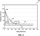
- FIGURE 3 is a chart that illustrates a temperature curve over time to illustrate the calculations performed according to an embodiment of the invention.
- the X-axis represents time (in minutes), and the Y-axis represents temperature (in degrees Fahrenheit).
- the horizontal line at -10° illustrates an example of air temperature 318.
- the horizontal line at +10° illustrates an example low temperature threshold 316.
- the values are illustrative only and are used to illustrate the result of the computations. Real world values may vary, as oil temperature may be different, rate of decay may be different, low temperature threshold may be lower or higher, and ambient temperatures may vary (and may not be constant).
- the previous oil temperature was 170°, and the previous interval time was 54 minutes. Accordingly, the computation at block 224 resulted in a subsequent interval time of 32 minutes.
- the previous oil temperature was 70°, and the previous interval time was 32 minutes. Accordingly, the computation at block 224 resulted in a subsequent interval time of 31 minutes.
- the previous oil temperature was 40°, and the previous interval time was 31 minutes. Accordingly, the computation at block 224 resulted in a subsequent interval time of 18 minutes.
- the dashed line 312 at time 145 indicates the state at block 224 again, where a current oil temperature is measured as approximately 14°.
- the previous oil temperature was 21°, and the previous interval time was 18 minutes. Accordingly, the computation at block 224 resulted in a subsequent interval time of 9 minutes.
- the above general techniques will result in different behavior for different values. For example, if the ambient temperature is much closer to the low temperature threshold, the computed intervals will be longer on average because the oil temperature will approach the low temperature threshold more slowly. Also, if the ambient temperature is lower, or if the starting oil temperature is lower, then the computed intervals will be shorter on average.
Landscapes
- Engineering & Computer Science (AREA)
- Chemical & Material Sciences (AREA)
- Combustion & Propulsion (AREA)
- Mechanical Engineering (AREA)
- General Engineering & Computer Science (AREA)
- Life Sciences & Earth Sciences (AREA)
- Atmospheric Sciences (AREA)
- Combined Controls Of Internal Combustion Engines (AREA)
Abstract
Description
- Prior art document
KR20130013176A1 - The invention is defined by the appended claims.
- The foregoing aspects and many of the attendant advantages of this invention will become more readily appreciated as the same become better understood by reference to the following detailed description, when taken in conjunction with the accompanying drawings, wherein:
-
FIGURE 1 is a block diagram that illustrates a controller of a vehicle according to an embodiment of the invention; -
FIGURES 2A-2B are a flowchart that illustrates an embodiment of a method of managing temperature in a vehicle according to the invention; and -
FIGURE 3 is a chart that illustrates a temperature curve over time to illustrate the calculations performed according to the invention. -
FIGURE 1 is a block diagram that illustrates a controller of a vehicle according to an embodiment of the invention. In some embodiments, thevehicle 100 uses diesel fuel. In some embodiments, thevehicle 100 is a Class 8 truck. In some embodiments, thevehicle 100 may be any type of vehicle for which a minimum temperature must be maintained at all times in order to ensure operability. As shown, thevehicle 100 includes anengine 110, anoil temperature sensor 112, anair temperature sensor 114, one or moreelectronic cab components 106, an engine control module (ECM) 108, anignition bus 104, and atemperature monitoring controller 102. Atypical vehicle 100 will contain many more components known to one of ordinary skill in the art, but which are not illustrated or described herein for the sake of clarity. - In some embodiments, the
engine 110 is an internal combustion engine. In some embodiments, theengine 110 is configured to be powered by a diesel fuel blend. In some embodiments, the ECM 108 is configured to control various aspects of theengine 110 while operating, including but not limited to ignition timing, idle speed, and air/fuel ratio. To support these actions, the ECM 108 receives data from a plurality of sensors, including theoil temperature sensor 112 and theair temperature sensor 114. Theoil temperature sensor 112 is configured to measure a temperature of oil in theengine 110, an oil reservoir, or elsewhere in thevehicle 100. Theoil temperature sensor 112 is configured to generate oil temperature values and provide them to theECM 108. Theair temperature sensor 114 is configured to measure an ambient temperature outside of thevehicle 100. Like theoil temperature sensor 112, theair temperature sensor 114 is configured to generate air temperature values and provide them to theECM 108. In some embodiments, theelectronic cab components 106 are one or more devices within a cab of thevehicle 100. Theelectronic cab components 106 may include, but are not limited to, lights, warning indicator displays, audible alarms/alerts, and blower fans. - In some embodiments, the
ignition bus 104 controls whether various other components of thevehicle 100 receive electrical power. For example, in some embodiments, when theignition bus 104 is in a powered off state, theelectronic cab components 106 and ECM 108 do not receive electrical power (or, at least, do not receive enough electrical power to provide functionality). Meanwhile, when theignition bus 104 is in a powered on state, theengine 110,electronic cab components 106, and ECM 108 receive power. If a starter is engaged while theignition bus 104 is in the powered on state, theengine 110 may start, and theignition bus 104 must be in the powered on state for theengine 110 to run. However, theignition bus 104 may be in the powered on state without theengine 110 starting. In some embodiments, one or more of theelectronic cab components 106 may be activated upon receiving power from theignition bus 104, and may not be configurable to remain deactivated if power is received. - In diesel vehicles such as Class 8 trucks, a technical problem exists in that the fuel experiences "gelling" at low temperatures. One technique for avoiding gelling is to run the
engine 110 in order to maintain fuel temperature above a low temperature threshold. However, running theengine 110 constantly wastes fuel and pollutes the environment, particularly when thevehicle 100 will be stationary for long periods of time (such as when an operator of thevehicle 100 is resting overnight in a truck sleeper). In such situations, theengine 110 instead may be shut down and automatically restarted periodically in order to maintain the fuel temperature above the low temperature threshold. - It would be advantageous to only restart the
engine 110 when needed to maintain temperature, because fuel could be conserved and pollution could be reduced. However, several technical problems exist in doing so within existingvehicle 100 configurations. For example, in some embodiments, the ECM 108 is only active to receive sensor values if it is receiving power from theignition bus 104. This leads to a problem, in that theignition bus 104 must be powered on in order to receive sensor values to check if theengine 110 should be automatically started. As stated above, if theignition bus 104 is in the powered on state, at least some of theelectronic cab components 106 will also be powered on. If the operator is trying to sleep in the truck sleeper, powering on theelectronic cab components 106 will disturb the operator. This can lead to the operator receiving less rest (and the corresponding detriment to safety), or to the operator disabling the auto start feature and simply not turning off theengine 110 while resting (and the corresponding waste of fuel and increased pollution). - While a predetermined interval could be used to check temperature (e.g., place the
ignition bus 104 in the powered on state every 10 minutes to check the temperature), this is undesirable for multiple reasons. For example, if the predetermined interval is set too short, theignition bus 104 will be powered on unnecessarily. As another example, if the predetermined interval is set too long, the fuel temperature may fall below the gelling temperature before the auto-start can be engaged. What is desirable is a controller that can monitor the temperature in such a way that increases the interval time between the powering on of theignition bus 104 when possible, but that also can ensure that the temperature will be checked before it crosses the low temperature threshold. What is also desirable is a controller that can provide such functionality without having to retrofit avehicle 100 to include additional sensors that can be used without powering on theignition bus 104. - To provide these (and other) advantages, the
vehicle 100 includes atemperature monitoring controller 102. In some embodiments, thetemperature monitoring controller 102 is a processor, control module, or other suitable hardware that is configured to receive sensor values from theECM 108 and to decide when theengine 110 should be automatically started. In some embodiments, thetemperature monitoring controller 102 is powered separately from theignition bus 104, and so can operate even when theignition bus 104 is in the powered off state. In some embodiments, thetemperature monitoring controller 102 may be incorporated into a portion of the ECM 108 that receives power even while theignition bus 104 is in the powered off state. In some embodiments, when thetemperature monitoring controller 102 determines that theengine 110 should be automatically started in order to maintain temperature, thetemperature monitoring controller 102 can cause theengine 110 to be started using any suitable technique, including but not limited to engaging a starter and transmitting an instruction or other signal to theECM 108. Further details of how thetemperature monitoring controller 102 decides when to automatically start theengine 110 and when to place theignition bus 104 in the powered on state are provided below. -
FIGURES 2A-2B are a flowchart that illustrates an embodiment of a method of managing temperature in a vehicle according to the invention. From a start block, themethod 200 proceeds toblock 202, where anengine 110 of avehicle 100 is placed in a stopped state. Placing theengine 110 in the stopped state may include placing theignition bus 104 in the powered off state. Next, atblock 204, atemperature monitoring controller 102 of thevehicle 100 causes theignition bus 104 to be placed in a powered on state (assuming it was previously in the powered off state). With theignition bus 104 in the powered on state, thetemperature monitoring controller 102 can request sensor values from theECM 108. - At
block 206, thetemperature monitoring controller 102 obtains an initial oil temperature value from anoil temperature sensor 112 and an air temperature value from anair temperature sensor 114. As noted above, the values may be obtained from theECM 108, as opposed to directly from the sensors. In some embodiments, thetemperature monitoring controller 102 may be able to receive the values directly from the sensors, but ignition bus power is still needed to activate the sensors. It should also be noted that in the illustrated and described embodiments, thetemperature monitoring controller 102 is using oil temperature as a proxy for fuel temperature, at least because theoil temperature sensor 112 is widely installed and available. In other embodiments, other values may be used to determine the fuel temperature, such as a different proxy value, or a direct measurement of the fuel temperature itself. - A test is then performed to determine whether the air temperature value is greater than a low temperature threshold. As known to one of ordinary skill in the art, the oil temperature will generally be warmer than the ambient temperature when the
engine 110 is running, and will decay to the ambient temperature when theengine 110 is not running. If the air temperature is greater than the low temperature threshold, then it is unlikely that oil temperature will drop below the low temperature threshold (though it is advisable to continue to check, in case the ambient temperature falls). The low temperature threshold is temperature value below which engine may have reliability problems, including but not limited to fuel gelling. - In some embodiments, the low temperature threshold may be configured by the vehicle operator. Since the illustrated
method 200 is intended to make sure that the fuel does not fall below its gelling temperature, the vehicle operator may set the low temperature threshold based on a gelling temperature of a particular fuel blend being used. In some embodiments, thevehicle 100 may provide an interface that allows the vehicle operator to directly enter the low temperature threshold. In some embodiments, thevehicle 100 may be programmed with low temperature thresholds for various fuel blends, and the vehicle operator may select a fuel blend in order to configure the low temperature threshold. In some embodiments, the vehicle operator may base the low temperature threshold on the gelling temperature of the fuel blend plus an offset, for safety. In the flowchart, the low temperature threshold is illustrated as TEMPCRANK. - If the test determined that the air temperature value is greater than the low temperature threshold, then the result of the determination at
decision block 208 is YES, and themethod 200 proceeds to block 210. The illustrated embodiment describes this test as "greater than," though in some embodiments, the test may instead determine whether the air temperature value is greater than or equal to the low temperature threshold. - At
block 210, thetemperature monitoring controller 102 sets an interval time to a maximum initial interval value. One example maximum initial interval value is any value between 30 minutes and 90 minutes, such as 60 minutes. Because the oil temperature value is unlikely to ever reach the low temperature threshold if the air temperature value is above the low temperature threshold, the maximum initial interval value can be set to a high value to reduce intrusiveness. In some embodiments, the maximum initial interval value may be set to a given value (instead of to an infinite value or no value) so that it remains unlikely that the temperature will fall without thetemperature monitoring controller 102 reacting at all. In some embodiments, the maximum initial interval value may be configured by the vehicle operator. Themethod 200 then proceeds to a continuation terminal ("terminal B"). - Otherwise, if the test determined that the air temperature value is not greater than the low temperature threshold, then the result of the determination at
decision block 208 is NO, and themethod 200 proceeds to perform a test to determine whether the oil temperature value is less than or equal to the low temperature threshold. If the test determined that the oil temperature is less than or equal to the low temperature threshold, then the result of the determination atdecision block 212 is YES, and themethod 200 proceeds to a continuation terminal ("terminal C"). In some embodiments, the low temperature threshold would be set by the vehicle operator to be higher than the gelling temperature of the fuel blend, since reaching the gelling temperature would be too late. Since themethod 200 would be atblock 204 soon after theengine 110 was turned off (and theengine 110 was successfully running before then), the oil temperature value would likely be between the gelling temperature of the fuel blend and the low temperature threshold due to the offset provided by the vehicle operator if themethod 200 has reached a point where result of the determination atdecision block 212 is YES. Again, as above, though the illustrated embodiment describes this determination as "less than or equal to," in some embodiments, this determination may be "less than." - Otherwise, if the oil temperature value is not less than or equal to the low temperature threshold, then the result of the determination at
decision block 212 is NO, and themethod 200 proceeds to another continuation terminal ("terminal A"). From terminal A (FIGURE 2B ), themethod 200 proceeds to block 214, where thetemperature monitoring controller 102 sets an interval time to a minimum initial interval value. One example minimum initial interval value is any value between one minute and twenty minutes, such as ten minutes. The minimum initial interval value may be selected to be short enough to reduce the risk of a significant temperature drop, but while remaining large enough to provide a meaningful difference between the oil temperature value at the start of the interval and at the end of the interval such that a rate of change may be determined. In some embodiments, the minimum initial interval value may be configured by the vehicle operator. - The
method 200 then proceeds to terminal B, and then to block 220, where thetemperature monitoring controller 102 causes theignition bus 104 to be placed in a powered off state. As described above, while theignition bus 104 is in the powered off state, theelectronic cab components 106, theECM 108, and thesensors - Next, the
temperature monitoring controller 102 waits for the interval time. One of ordinary skill in the art will recognize that blocks 220-226 of themethod 200 constitute a loop. The first time through the loop, the interval time will be either the maximum initial interval time assigned inblock 210, or the minimum initial interval time assigned inblock 214. For example, if the interval time was set to a minimum initial interval value of ten minutes, then thetemperature monitoring controller 102 waits for ten minutes before themethod 200 proceeds. On subsequent times through the loop (if any), the interval time will be the time determined inblock 224 as described below. - At
block 222, after waiting for the interval time, thetemperature monitoring controller 102 causes theignition bus 104 to be placed in a powered on state. In the powered on state, power is supplied to theECM 108, and therefore values may be obtained from thesensors electronic cab components 106, which may cause them to flash lights, sound alerts, activate blowers, and so on. In some embodiments, power may be withheld from one or more of theelectronic cab components 106 when theignition bus 104 is placed in the powered on state, if possible. - Next, at
block 224, thetemperature monitoring controller 102 obtains a current oil temperature value from theoil temperature sensor 112. As described above, the value may be obtained via theECM 108, or directly from theoil temperature sensor 112. Atblock 226, thetemperature monitoring controller 102 determines a subsequent interval time based on the previous interval time, the previous oil temperature value, and the current oil temperature value. For the time through the loop of blocks 220-228, the previous interval time will be the initial interval time, and the previous oil temperature value will be the initial oil temperature value. For subsequent times through the loop of blocks 220-228, if any, the current oil temperature value and the subsequent interval time will be used. - In some embodiments, the rate of change of the oil temperature is used to predict the future time at which the oil temperature will reach the low temperature threshold. Oil temperature experiences exponential decay when exposed to a lower ambient temperature, and so the rate of change observed between any two discrete oil temperature readings will be a conservative estimate of the time, thus increasing the likelihood that the
engine 110 will be automatically started before reaching the low temperature threshold while allowing for increased interval times when appropriate. - In some embodiments, the subsequent interval time may be determined using a formula similar to the following:

- T: Subsequent interval time (in minutes)
- TEMPCRANK : low temperature threshold (in degrees)
- TEMPC : current oil temperature (in degrees)
- TEMPP : previous oil temperature (in degrees)
- INTC : previous/current interval time (in minutes)
- In some embodiments, other formulas may be used that predict the time at which the current oil temperature will reach the low temperature threshold. For example, instead of using a conservative linear model for the prediction, an exponential decay model may be used in order to more accurately predict the point when the low temperature threshold may be reached.
- Once the subsequent interval time is determined, a test is performed to determine whether the subsequent interval time is lower than a threshold interval time. In some embodiments, the threshold interval time may be selected based on an interval time that would be too short to provide relief to the vehicle operator. In other words, the threshold interval time would be set to a point at which, if the
electronic cab components 106 were activated that frequently, it would be likely to disturb the vehicle operator. In some embodiments, the threshold interval time may be configured by the vehicle operator. In some embodiments, the threshold interval time may be any suitable value, such as between one minute and twenty minutes. One such value is ten minutes. In some embodiments, the threshold interval time may be set equal to the minimum initial interval value. In some embodiments, the threshold interval time should be set lower than or equal to the minimum initial interval value. - In some embodiments, the
temperature monitoring controller 102 could check the oil temperature value to determine if it is at or below the low temperature threshold (or within an offset of the low temperature threshold), instead of using the subsequent interval time as a proxy for the low temperature threshold. However, using the interval time threshold provides a benefit, in that it avoids rapid cycling of the ignition bus when approaching the low temperature threshold. - If the test has determined that the subsequent interval time is greater than or equal to the threshold interval time, then the result of the determination at
decision block 228 is NO, and themethod 200 returns to block 220. In the next pass through the loop of blocks 220-226, the subsequent interval time determined inblock 226 is used as the new interval time. In some embodiments, the subsequent interval time may be limited by a ceiling such as the maximum initial interval value. - Otherwise, if the test has determined that the subsequent interval time is lower than a threshold interval time, then the result of the determination at
decision block 228 is YES, and themethod 200 proceeds to terminal C, and then to block 230, where thetemperature monitoring controller 102 causes theengine 110 to be automatically started. Theengine 110 will then run to bring thevehicle 100 up to an acceptable temperature. In some embodiments, theengine 110 may run for a predetermined amount of time. In some embodiments, theengine 110 may run until the oil temperature reaches a high temperature threshold. In some embodiments, theengine 110 may run for any other suitable amount of time. - The
method 200 then proceeds to an end block and terminates. - In some embodiments, the
method 200 may be executed multiple times whilevehicle 100 is otherwise off. For example, avehicle 100 may auto-start multiple times while parked over the course of a night if the ambient temperature is particularly cold, and may be auto-stopped at any suitable time. Each time the engine 120 stops, themethod 200 may be re-executed. - In some embodiments, the
vehicle 100 may be configured to enable or disable functionality of themethod 200. For example, if the air temperature is higher than a given threshold, or it is a given season and/or location (e.g., if the vehicle is in Texas in July, and/or the ambient temperature is 80 degrees F), thevehicle 100 may not perform themethod 200 at all, but may instead leave the engine off with no fear of reaching the low temperature threshold. In some embodiments, thevehicle 100 may determine this automatically using GPS and the average seasonal temperature of the location. In some embodiments, the functionality may be enabled or disabled by the vehicle operator. -
FIGURE 3 is a chart that illustrates a temperature curve over time to illustrate the calculations performed according to an embodiment of the invention. In thechart 300, the X-axis represents time (in minutes), and the Y-axis represents temperature (in degrees Fahrenheit). Thecurved line 302 is an example of oil temperature over time. At time=0, the oil temperature starts at 200° and exhibits exponential decay over time. The horizontal line at -10° illustrates an example ofair temperature 318. The horizontal line at +10° illustrates an examplelow temperature threshold 316. The values are illustrative only and are used to illustrate the result of the computations. Real world values may vary, as oil temperature may be different, rate of decay may be different, low temperature threshold may be lower or higher, and ambient temperatures may vary (and may not be constant). - In the
chart 300, time=0 indicates the state atblock 206 of themethod 200, and atblock 214, a minimum initial interval value of 10 minutes was set. The dashedline 304 at time=10 indicates the state atblock 224, where a current oil temperature is measured as approximately 170°. The previous oil temperature was 200°, and the previous interval time was 10 minutes. Accordingly, the computation atblock 224 resulted in a subsequent interval time of 54 minutes. - The dashed
line 306 at time=64 (54 minutes after time=10) indicates the state atblock 224 again, where a current oil temperature is measured as approximately 70°. The previous oil temperature was 170°, and the previous interval time was 54 minutes. Accordingly, the computation atblock 224 resulted in a subsequent interval time of 32 minutes. - The dashed
line 308 at time=96 (32 minutes after time=64) indicates the state atblock 224 again, where a current oil temperature is measured as approximately 40°. The previous oil temperature was 70°, and the previous interval time was 32 minutes. Accordingly, the computation atblock 224 resulted in a subsequent interval time of 31 minutes. - The dashed
line 310 at time=127 (31 minutes after time=96) indicates the state atblock 224 again, where a current oil temperature is measured as approximately 21°. The previous oil temperature was 40°, and the previous interval time was 31 minutes. Accordingly, the computation atblock 224 resulted in a subsequent interval time of 18 minutes. - The dashed line 312 at time 145 (18 minutes after time=127) indicates the state at
block 224 again, where a current oil temperature is measured as approximately 14°. The previous oil temperature was 21°, and the previous interval time was 18 minutes. Accordingly, the computation atblock 224 resulted in a subsequent interval time of 9 minutes. - The dashed line 314 at time 154 (9 minutes after time=145) indicates a point where the
oil temperature 302 reached the low temperature threshold. If the threshold interval time had been set to 10 minutes, theengine 110 would have been automatically started at time=145, when the subsequent interval time was computed to be less than the threshold interval time. One will notice that the first computed interval time was 54 minutes, and the last computed interval time greater than the threshold was 18 minutes, for an average interval time of 33.75 minutes. - One of ordinary skill in the art will recognize that the above general techniques will result in different behavior for different values. For example, if the ambient temperature is much closer to the low temperature threshold, the computed intervals will be longer on average because the oil temperature will approach the low temperature threshold more slowly. Also, if the ambient temperature is lower, or if the starting oil temperature is lower, then the computed intervals will be shorter on average.
Claims (15)
- A method of automatically managing temperature in a vehicle, the method comprising:obtaining, by a temperature monitoring controller, a current fuel temperature value from a fuel temperature sensor;determining, by the temperature monitoring controller, an interval time representing a time period after which a fuel temperature is predicted to drop below a low temperature threshold, wherein the determination is based on at least a previous interval time, a previous fuel temperature value, and the current fuel temperature value;in response to determining that the interval time is greater than a threshold interval time, waiting, by the temperature monitoring controller, for the interval time before obtaining a subsequent fuel temperature value from the fuel temperature sensor; andin response to determining that the interval time is not greater than the threshold interval time, causing, by the temperature monitoring controller, an engine of the vehicle to be started.
- The method of Claim 1, wherein obtaining a current fuel temperature value from a fuel temperature sensor comprises powering on an ignition bus of the vehicle.
- The method of any of Claims 1-2, further comprising, in response to determining that the interval time is greater than the threshold interval time, powering off an ignition bus of the vehicle.
- The method of any of Claims 1-3, further comprising determining, by the temperature monitoring controller, an initial interval time, wherein determining the initial interval time comprises:obtaining, by the temperature monitoring controller, an initial fuel temperature value from a fuel temperature sensor and an air temperature value from an air temperature sensor;determining whether the air temperature value is greater than the low temperature threshold;in response to determining that the air temperature value is greater than the low temperature threshold, setting the initial interval time to a predetermined maximum initial interval value; andin response to determining that the air temperature value is not greater than the low temperature threshold:determining whether the initial fuel temperature value is less than the low temperature threshold;in response to determining that the initial fuel temperature value is less than the low temperature threshold, causing the engine of the vehicle to be started; andin response to determining that the initial fuel temperature value is not less than the low temperature threshold, setting the initial interval time to a predetermined minimum initial interval value.
- The method of any of Claims 1-4, wherein determining the interval time representing a time at which a fuel temperature is predicted to drop below a low temperature threshold based on at least a previous interval time, a previous fuel temperature value, and the current fuel temperature value comprises:multiplying a difference between the current fuel temperature value and the low temperature threshold by the previous interval time to obtain a first result;determining a difference between the current fuel temperature value and the previous fuel temperature value to obtain a second result; anddividing the first result by the second result to obtain the interval time.
- The method of Claim 5, further comprising setting the interval time to a predetermined maximum interval time in response to determining that the interval time obtained by dividing the first result by the second result is greater than the predetermined maximum interval time.
- The method of any of Claims 1-6, wherein the low temperature threshold is configurable by an operator of the vehicle based on a fuel blend.
- The method of any of Claims 1-7, wherein the threshold interval time is configurable by an operator of the vehicle.
- The method of any of Claims 1-7, wherein the temperature monitoring controller either is using an oil temperature as a proxy for the fuel temperature value or is using other values to determine the fuel temperature value, such as a different proxy value, or a direct measurement of the fuel temperature itself.
- A computer-readable medium having computer-executable instructions stored thereon that, in response to execution by at least one processor in a vehicle, cause the vehicle to perform actions for automatically managing temperature in the vehicle as recited in any of Claims 1-9.
- A temperature monitoring controller for automatically managing temperature in a vehicle, wherein the temperature monitoring controller is configured to perform actions for automatically managing temperature in the vehicle as recited in any of Claims 1-9.
- A vehicle comprising a temperature monitoring controller according to the previous claim.
- The vehicle of Claim 12, comprising a diesel engine.
- The vehicle of Claim 13, wherein the vehicle is a Class 8 truck.
- The vehicle of any of Claims 12-14, wherein the vehicle includes a truck sleeper.
Applications Claiming Priority (2)
| Application Number | Priority Date | Filing Date | Title |
|---|---|---|---|
| US201762474479P | 2017-03-21 | 2017-03-21 | |
| EP18163044.3A EP3379061B1 (en) | 2017-03-21 | 2018-03-21 | Systems and methods for automatically monitoring and controlling temperature for a vehicle |
Related Parent Applications (1)
| Application Number | Title | Priority Date | Filing Date |
|---|---|---|---|
| EP18163044.3A Division EP3379061B1 (en) | 2017-03-21 | 2018-03-21 | Systems and methods for automatically monitoring and controlling temperature for a vehicle |
Publications (2)
| Publication Number | Publication Date |
|---|---|
| EP3702602A1 true EP3702602A1 (en) | 2020-09-02 |
| EP3702602B1 EP3702602B1 (en) | 2025-05-07 |
Family
ID=61731668
Family Applications (2)
| Application Number | Title | Priority Date | Filing Date |
|---|---|---|---|
| EP20169871.9A Active EP3702602B1 (en) | 2017-03-21 | 2018-03-21 | Systems and methods for automatically monitoring and controlling temperature for a vehicle |
| EP18163044.3A Active EP3379061B1 (en) | 2017-03-21 | 2018-03-21 | Systems and methods for automatically monitoring and controlling temperature for a vehicle |
Family Applications After (1)
| Application Number | Title | Priority Date | Filing Date |
|---|---|---|---|
| EP18163044.3A Active EP3379061B1 (en) | 2017-03-21 | 2018-03-21 | Systems and methods for automatically monitoring and controlling temperature for a vehicle |
Country Status (3)
| Country | Link |
|---|---|
| US (2) | US10487719B2 (en) |
| EP (2) | EP3702602B1 (en) |
| CA (1) | CA2998628A1 (en) |
Families Citing this family (6)
| Publication number | Priority date | Publication date | Assignee | Title |
|---|---|---|---|---|
| US10487719B2 (en) | 2017-03-21 | 2019-11-26 | Paccar Inc | Systems and methods for automatically monitoring and controlling temperature for a vehicle |
| US10934933B2 (en) | 2018-08-31 | 2021-03-02 | Paccar Inc | Fuel gelling prevention using engine auto start functionality |
| CN114562370A (en) * | 2021-03-31 | 2022-05-31 | 长城汽车股份有限公司 | Vehicle starting method and device and vehicle |
| US11702952B2 (en) * | 2021-11-11 | 2023-07-18 | General Electric Company | Thermal bias control in turbomachines |
| US11960336B2 (en) | 2022-05-06 | 2024-04-16 | Waymo Llc | Method of temperature conditioning compute module for cold start |
| CN116678516B (en) * | 2023-05-24 | 2026-04-10 | 中国第一汽车股份有限公司 | Oil temperature threshold determination method and vehicle |
Citations (3)
| Publication number | Priority date | Publication date | Assignee | Title |
|---|---|---|---|---|
| EP1348895A2 (en) * | 2002-03-29 | 2003-10-01 | JATCO Ltd | Hydraulic system for automatic transmission for vehicle having idle-stop control |
| JP2008215332A (en) * | 2007-03-08 | 2008-09-18 | Bigban:Kk | Starting system for diesel engine and starting method thereof |
| KR20130013176A (en) | 2011-07-27 | 2013-02-06 | 현대자동차주식회사 | System and method for preventing fuel freezing of diesel vehicle |
Family Cites Families (13)
| Publication number | Priority date | Publication date | Assignee | Title |
|---|---|---|---|---|
| US3942024A (en) * | 1974-10-11 | 1976-03-02 | Ingham Dickey E | Automobile engine warmer |
| US4192274A (en) * | 1975-06-09 | 1980-03-11 | Damon Ralph S | Diesel fueled engine coolant heater |
| US4563987A (en) * | 1984-02-01 | 1986-01-14 | Arrow Specialty Company | Automatic engine control system |
| US5063513A (en) * | 1990-06-15 | 1991-11-05 | Nartron Corporation | Vehicle preheater control |
| US6928972B2 (en) * | 2001-01-31 | 2005-08-16 | Csxt Intellectual Properties Corporation | Locomotive and auxiliary power unit engine controller |
| US7290517B2 (en) * | 2005-07-28 | 2007-11-06 | Caterpillar Inc. | Automatic start-up of an auxiliary power unit |
| US20090312894A1 (en) * | 2008-06-17 | 2009-12-17 | General Electric Company | Method, system, and computer readable storage medium for controlling engine starts |
| GB2499253B (en) * | 2012-02-13 | 2015-09-30 | Jaguar Land Rover Ltd | Heater and method of operation therefor |
| FR3020398B1 (en) * | 2014-04-24 | 2016-04-01 | Renault Sas | MANAGING THE HEATING OF A MOTOR VEHICLE COMBUSTION ENGINE |
| WO2018042337A1 (en) * | 2016-09-01 | 2018-03-08 | Sabic Global Technologies B.V. | Olefin plant optimization using steady-state models |
| US10859056B2 (en) * | 2016-10-19 | 2020-12-08 | Bostic Motors Inc. | Electronic control for engine block heater elements |
| US10487719B2 (en) | 2017-03-21 | 2019-11-26 | Paccar Inc | Systems and methods for automatically monitoring and controlling temperature for a vehicle |
| US10947945B2 (en) * | 2017-10-20 | 2021-03-16 | Lee J. Santoro | Methods and systems for control of electric components |
-
2018
- 2018-03-20 US US15/926,448 patent/US10487719B2/en active Active
- 2018-03-20 CA CA2998628A patent/CA2998628A1/en active Pending
- 2018-03-21 EP EP20169871.9A patent/EP3702602B1/en active Active
- 2018-03-21 EP EP18163044.3A patent/EP3379061B1/en active Active
-
2019
- 2019-10-30 US US16/669,162 patent/US10989103B2/en active Active
Patent Citations (3)
| Publication number | Priority date | Publication date | Assignee | Title |
|---|---|---|---|---|
| EP1348895A2 (en) * | 2002-03-29 | 2003-10-01 | JATCO Ltd | Hydraulic system for automatic transmission for vehicle having idle-stop control |
| JP2008215332A (en) * | 2007-03-08 | 2008-09-18 | Bigban:Kk | Starting system for diesel engine and starting method thereof |
| KR20130013176A (en) | 2011-07-27 | 2013-02-06 | 현대자동차주식회사 | System and method for preventing fuel freezing of diesel vehicle |
Also Published As
| Publication number | Publication date |
|---|---|
| US10487719B2 (en) | 2019-11-26 |
| CA2998628A1 (en) | 2018-09-21 |
| EP3702602B1 (en) | 2025-05-07 |
| EP3379061A1 (en) | 2018-09-26 |
| US20180274432A1 (en) | 2018-09-27 |
| US20200165959A1 (en) | 2020-05-28 |
| EP3379061B1 (en) | 2020-05-13 |
| US10989103B2 (en) | 2021-04-27 |
Similar Documents
| Publication | Publication Date | Title |
|---|---|---|
| US10989103B2 (en) | Systems and methods for automatically monitoring and controlling temperature for a vehicle | |
| US8086395B2 (en) | In-vehicle navigation system | |
| US7921705B2 (en) | Engine coolant temperature estimation system | |
| US9790884B2 (en) | Control system and control method of vehicle | |
| JP4956476B2 (en) | Battery discharge duration prediction method, battery state detection method, battery state detection device, and battery power supply system | |
| CN114233549B (en) | Managing automatic stop/start frequency | |
| US8773136B2 (en) | Method for evaluating the ability of a battery to start | |
| CN110608106B (en) | Temperature treatment method and device | |
| KR101886104B1 (en) | Control apparatus and method for cooling fan of vehicle | |
| US20210164391A1 (en) | Fuel gelling prevention using engine auto start functionality | |
| CN112537308B (en) | Mode selector module for vehicle components | |
| US9932951B2 (en) | Engine start stop system based on programmable battery voltage levels | |
| CN115306617B (en) | Method, device and equipment for quickly warming up engine and readable storage medium | |
| US11686237B2 (en) | Controlling NOx emission control during start of a vehicle | |
| JP5203496B2 (en) | Battery state detection method, battery state detection device, and battery power supply system | |
| JP4538852B2 (en) | Vehicle control device | |
| JP2015113793A (en) | Vehicle controller | |
| JPH1182263A (en) | Unattended engine starter | |
| KR101150939B1 (en) | Idle Stop and Go Apparatus and Control Method thereof | |
| JP4825156B2 (en) | Engine oil condition monitoring device | |
| JP3005860B1 (en) | Automatic engine start method and apparatus | |
| CN118209255A (en) | Method and device for detecting leakage of cooling liquid of hybrid electric vehicle engine and storage medium | |
| JPH06317241A (en) | Automatic engine start / stop device |
Legal Events
| Date | Code | Title | Description |
|---|---|---|---|
| PUAI | Public reference made under article 153(3) epc to a published international application that has entered the european phase |
Free format text: ORIGINAL CODE: 0009012 |
|
| STAA | Information on the status of an ep patent application or granted ep patent |
Free format text: STATUS: THE APPLICATION HAS BEEN PUBLISHED |
|
| AC | Divisional application: reference to earlier application |
Ref document number: 3379061 Country of ref document: EP Kind code of ref document: P |
|
| AK | Designated contracting states |
Kind code of ref document: A1 Designated state(s): AL AT BE BG CH CY CZ DE DK EE ES FI FR GB GR HR HU IE IS IT LI LT LU LV MC MK MT NL NO PL PT RO RS SE SI SK SM TR |
|
| STAA | Information on the status of an ep patent application or granted ep patent |
Free format text: STATUS: REQUEST FOR EXAMINATION WAS MADE |
|
| 17P | Request for examination filed |
Effective date: 20210122 |
|
| RBV | Designated contracting states (corrected) |
Designated state(s): AL AT BE BG CH CY CZ DE DK EE ES FI FR GB GR HR HU IE IS IT LI LT LU LV MC MK MT NL NO PL PT RO RS SE SI SK SM TR |
|
| STAA | Information on the status of an ep patent application or granted ep patent |
Free format text: STATUS: EXAMINATION IS IN PROGRESS |
|
| 17Q | First examination report despatched |
Effective date: 20221019 |
|
| GRAP | Despatch of communication of intention to grant a patent |
Free format text: ORIGINAL CODE: EPIDOSNIGR1 |
|
| STAA | Information on the status of an ep patent application or granted ep patent |
Free format text: STATUS: GRANT OF PATENT IS INTENDED |
|
| INTG | Intention to grant announced |
Effective date: 20241202 |
|
| GRAS | Grant fee paid |
Free format text: ORIGINAL CODE: EPIDOSNIGR3 |
|
| GRAA | (expected) grant |
Free format text: ORIGINAL CODE: 0009210 |
|
| STAA | Information on the status of an ep patent application or granted ep patent |
Free format text: STATUS: THE PATENT HAS BEEN GRANTED |
|
| AC | Divisional application: reference to earlier application |
Ref document number: 3379061 Country of ref document: EP Kind code of ref document: P |
|
| AK | Designated contracting states |
Kind code of ref document: B1 Designated state(s): AL AT BE BG CH CY CZ DE DK EE ES FI FR GB GR HR HU IE IS IT LI LT LU LV MC MK MT NL NO PL PT RO RS SE SI SK SM TR |
|
| REG | Reference to a national code |
Ref country code: GB Ref legal event code: FG4D |
|
| REG | Reference to a national code |
Ref country code: CH Ref legal event code: EP |
|
| REG | Reference to a national code |
Ref country code: DE Ref legal event code: R096 Ref document number: 602018081842 Country of ref document: DE |
|
| REG | Reference to a national code |
Ref country code: IE Ref legal event code: FG4D |
|
| P01 | Opt-out of the competence of the unified patent court (upc) registered |
Free format text: CASE NUMBER: APP_22365/2025 Effective date: 20250512 |
|
| REG | Reference to a national code |
Ref country code: SE Ref legal event code: TRGR |
|
| REG | Reference to a national code |
Ref country code: NL Ref legal event code: FP |
|
| PG25 | Lapsed in a contracting state [announced via postgrant information from national office to epo] |
Ref country code: PT Free format text: LAPSE BECAUSE OF FAILURE TO SUBMIT A TRANSLATION OF THE DESCRIPTION OR TO PAY THE FEE WITHIN THE PRESCRIBED TIME-LIMIT Effective date: 20250908 Ref country code: ES Free format text: LAPSE BECAUSE OF FAILURE TO SUBMIT A TRANSLATION OF THE DESCRIPTION OR TO PAY THE FEE WITHIN THE PRESCRIBED TIME-LIMIT Effective date: 20250507 Ref country code: FI Free format text: LAPSE BECAUSE OF FAILURE TO SUBMIT A TRANSLATION OF THE DESCRIPTION OR TO PAY THE FEE WITHIN THE PRESCRIBED TIME-LIMIT Effective date: 20250507 |
|
| REG | Reference to a national code |
Ref country code: LT Ref legal event code: MG9D |
|
| PG25 | Lapsed in a contracting state [announced via postgrant information from national office to epo] |
Ref country code: NO Free format text: LAPSE BECAUSE OF FAILURE TO SUBMIT A TRANSLATION OF THE DESCRIPTION OR TO PAY THE FEE WITHIN THE PRESCRIBED TIME-LIMIT Effective date: 20250807 Ref country code: GR Free format text: LAPSE BECAUSE OF FAILURE TO SUBMIT A TRANSLATION OF THE DESCRIPTION OR TO PAY THE FEE WITHIN THE PRESCRIBED TIME-LIMIT Effective date: 20250808 |
|
| PG25 | Lapsed in a contracting state [announced via postgrant information from national office to epo] |
Ref country code: PL Free format text: LAPSE BECAUSE OF FAILURE TO SUBMIT A TRANSLATION OF THE DESCRIPTION OR TO PAY THE FEE WITHIN THE PRESCRIBED TIME-LIMIT Effective date: 20250507 |
|
| REG | Reference to a national code |
Ref country code: AT Ref legal event code: MK05 Ref document number: 1792694 Country of ref document: AT Kind code of ref document: T Effective date: 20250507 |
|
| PG25 | Lapsed in a contracting state [announced via postgrant information from national office to epo] |
Ref country code: BG Free format text: LAPSE BECAUSE OF FAILURE TO SUBMIT A TRANSLATION OF THE DESCRIPTION OR TO PAY THE FEE WITHIN THE PRESCRIBED TIME-LIMIT Effective date: 20250507 |
|
| PG25 | Lapsed in a contracting state [announced via postgrant information from national office to epo] |
Ref country code: HR Free format text: LAPSE BECAUSE OF FAILURE TO SUBMIT A TRANSLATION OF THE DESCRIPTION OR TO PAY THE FEE WITHIN THE PRESCRIBED TIME-LIMIT Effective date: 20250507 |
|
| PG25 | Lapsed in a contracting state [announced via postgrant information from national office to epo] |
Ref country code: AT Free format text: LAPSE BECAUSE OF FAILURE TO SUBMIT A TRANSLATION OF THE DESCRIPTION OR TO PAY THE FEE WITHIN THE PRESCRIBED TIME-LIMIT Effective date: 20250507 |
|
| PG25 | Lapsed in a contracting state [announced via postgrant information from national office to epo] |
Ref country code: RS Free format text: LAPSE BECAUSE OF FAILURE TO SUBMIT A TRANSLATION OF THE DESCRIPTION OR TO PAY THE FEE WITHIN THE PRESCRIBED TIME-LIMIT Effective date: 20250807 |
|
| PG25 | Lapsed in a contracting state [announced via postgrant information from national office to epo] |
Ref country code: IS Free format text: LAPSE BECAUSE OF FAILURE TO SUBMIT A TRANSLATION OF THE DESCRIPTION OR TO PAY THE FEE WITHIN THE PRESCRIBED TIME-LIMIT Effective date: 20250907 |
|
| PG25 | Lapsed in a contracting state [announced via postgrant information from national office to epo] |
Ref country code: LV Free format text: LAPSE BECAUSE OF FAILURE TO SUBMIT A TRANSLATION OF THE DESCRIPTION OR TO PAY THE FEE WITHIN THE PRESCRIBED TIME-LIMIT Effective date: 20250507 |
|
| PG25 | Lapsed in a contracting state [announced via postgrant information from national office to epo] |
Ref country code: DK Free format text: LAPSE BECAUSE OF FAILURE TO SUBMIT A TRANSLATION OF THE DESCRIPTION OR TO PAY THE FEE WITHIN THE PRESCRIBED TIME-LIMIT Effective date: 20250507 Ref country code: SM Free format text: LAPSE BECAUSE OF FAILURE TO SUBMIT A TRANSLATION OF THE DESCRIPTION OR TO PAY THE FEE WITHIN THE PRESCRIBED TIME-LIMIT Effective date: 20250507 |
|
| PG25 | Lapsed in a contracting state [announced via postgrant information from national office to epo] |
Ref country code: CZ Free format text: LAPSE BECAUSE OF FAILURE TO SUBMIT A TRANSLATION OF THE DESCRIPTION OR TO PAY THE FEE WITHIN THE PRESCRIBED TIME-LIMIT Effective date: 20250507 |
|
| PG25 | Lapsed in a contracting state [announced via postgrant information from national office to epo] |
Ref country code: EE Free format text: LAPSE BECAUSE OF FAILURE TO SUBMIT A TRANSLATION OF THE DESCRIPTION OR TO PAY THE FEE WITHIN THE PRESCRIBED TIME-LIMIT Effective date: 20250507 |
|
| PG25 | Lapsed in a contracting state [announced via postgrant information from national office to epo] |
Ref country code: SK Free format text: LAPSE BECAUSE OF FAILURE TO SUBMIT A TRANSLATION OF THE DESCRIPTION OR TO PAY THE FEE WITHIN THE PRESCRIBED TIME-LIMIT Effective date: 20250507 Ref country code: RO Free format text: LAPSE BECAUSE OF FAILURE TO SUBMIT A TRANSLATION OF THE DESCRIPTION OR TO PAY THE FEE WITHIN THE PRESCRIBED TIME-LIMIT Effective date: 20250507 |
|
| REG | Reference to a national code |
Ref country code: DE Ref legal event code: R097 Ref document number: 602018081842 Country of ref document: DE |
|
| PLBE | No opposition filed within time limit |
Free format text: ORIGINAL CODE: 0009261 |
|
| STAA | Information on the status of an ep patent application or granted ep patent |
Free format text: STATUS: NO OPPOSITION FILED WITHIN TIME LIMIT |
|
| REG | Reference to a national code |
Ref country code: CH Ref legal event code: L10 Free format text: ST27 STATUS EVENT CODE: U-0-0-L10-L00 (AS PROVIDED BY THE NATIONAL OFFICE) Effective date: 20260318 |
|
| PGFP | Annual fee paid to national office [announced via postgrant information from national office to epo] |
Ref country code: SE Payment date: 20260327 Year of fee payment: 9 |
|
| PGFP | Annual fee paid to national office [announced via postgrant information from national office to epo] |
Ref country code: DE Payment date: 20260327 Year of fee payment: 9 |
|
| 26N | No opposition filed |
Effective date: 20260210 |
|
| PGFP | Annual fee paid to national office [announced via postgrant information from national office to epo] |
Ref country code: IT Payment date: 20260319 Year of fee payment: 9 |
|
| PGFP | Annual fee paid to national office [announced via postgrant information from national office to epo] |
Ref country code: NL Payment date: 20260319 Year of fee payment: 9 |
|
| PGFP | Annual fee paid to national office [announced via postgrant information from national office to epo] |
Ref country code: FR Payment date: 20260325 Year of fee payment: 9 |