EP1348895A2 - Hydraulic system for automatic transmission for vehicle having idle-stop control - Google Patents
Hydraulic system for automatic transmission for vehicle having idle-stop control Download PDFInfo
- Publication number
- EP1348895A2 EP1348895A2 EP03007018A EP03007018A EP1348895A2 EP 1348895 A2 EP1348895 A2 EP 1348895A2 EP 03007018 A EP03007018 A EP 03007018A EP 03007018 A EP03007018 A EP 03007018A EP 1348895 A2 EP1348895 A2 EP 1348895A2
- Authority
- EP
- European Patent Office
- Prior art keywords
- idle
- stop
- predetermined
- value
- time
- Prior art date
- Legal status (The legal status is an assumption and is not a legal conclusion. Google has not performed a legal analysis and makes no representation as to the accuracy of the status listed.)
- Granted
Links
Images


Classifications
-
- F—MECHANICAL ENGINEERING; LIGHTING; HEATING; WEAPONS; BLASTING
- F16—ENGINEERING ELEMENTS AND UNITS; GENERAL MEASURES FOR PRODUCING AND MAINTAINING EFFECTIVE FUNCTIONING OF MACHINES OR INSTALLATIONS; THERMAL INSULATION IN GENERAL
- F16H—GEARING
- F16H61/00—Control functions within control units of change-speed- or reversing-gearings for conveying rotary motion ; Control of exclusively fluid gearing, friction gearing, gearings with endless flexible members or other particular types of gearing
- F16H61/20—Preventing gear creeping ; Transmission control during standstill, e.g. hill hold control
-
- B—PERFORMING OPERATIONS; TRANSPORTING
- B60—VEHICLES IN GENERAL
- B60W—CONJOINT CONTROL OF VEHICLE SUB-UNITS OF DIFFERENT TYPE OR DIFFERENT FUNCTION; CONTROL SYSTEMS SPECIALLY ADAPTED FOR HYBRID VEHICLES; ROAD VEHICLE DRIVE CONTROL SYSTEMS FOR PURPOSES NOT RELATED TO THE CONTROL OF A PARTICULAR SUB-UNIT
- B60W10/00—Conjoint control of vehicle sub-units of different type or different function
- B60W10/04—Conjoint control of vehicle sub-units of different type or different function including control of propulsion units
- B60W10/06—Conjoint control of vehicle sub-units of different type or different function including control of propulsion units including control of combustion engines
-
- B—PERFORMING OPERATIONS; TRANSPORTING
- B60—VEHICLES IN GENERAL
- B60W—CONJOINT CONTROL OF VEHICLE SUB-UNITS OF DIFFERENT TYPE OR DIFFERENT FUNCTION; CONTROL SYSTEMS SPECIALLY ADAPTED FOR HYBRID VEHICLES; ROAD VEHICLE DRIVE CONTROL SYSTEMS FOR PURPOSES NOT RELATED TO THE CONTROL OF A PARTICULAR SUB-UNIT
- B60W10/00—Conjoint control of vehicle sub-units of different type or different function
- B60W10/10—Conjoint control of vehicle sub-units of different type or different function including control of change-speed gearings
- B60W10/11—Stepped gearings
- B60W10/115—Stepped gearings with planetary gears
-
- B—PERFORMING OPERATIONS; TRANSPORTING
- B60—VEHICLES IN GENERAL
- B60W—CONJOINT CONTROL OF VEHICLE SUB-UNITS OF DIFFERENT TYPE OR DIFFERENT FUNCTION; CONTROL SYSTEMS SPECIALLY ADAPTED FOR HYBRID VEHICLES; ROAD VEHICLE DRIVE CONTROL SYSTEMS FOR PURPOSES NOT RELATED TO THE CONTROL OF A PARTICULAR SUB-UNIT
- B60W30/00—Purposes of road vehicle drive control systems not related to the control of a particular sub-unit, e.g. of systems using conjoint control of vehicle sub-units, or advanced driver assistance systems for ensuring comfort, stability and safety or drive control systems for propelling or retarding the vehicle
- B60W30/18—Propelling the vehicle
- B60W30/18009—Propelling the vehicle related to particular drive situations
- B60W30/18018—Start-stop drive, e.g. in a traffic jam
-
- B—PERFORMING OPERATIONS; TRANSPORTING
- B60—VEHICLES IN GENERAL
- B60W—CONJOINT CONTROL OF VEHICLE SUB-UNITS OF DIFFERENT TYPE OR DIFFERENT FUNCTION; CONTROL SYSTEMS SPECIALLY ADAPTED FOR HYBRID VEHICLES; ROAD VEHICLE DRIVE CONTROL SYSTEMS FOR PURPOSES NOT RELATED TO THE CONTROL OF A PARTICULAR SUB-UNIT
- B60W30/00—Purposes of road vehicle drive control systems not related to the control of a particular sub-unit, e.g. of systems using conjoint control of vehicle sub-units, or advanced driver assistance systems for ensuring comfort, stability and safety or drive control systems for propelling or retarding the vehicle
- B60W30/18—Propelling the vehicle
- B60W30/18009—Propelling the vehicle related to particular drive situations
- B60W30/18054—Propelling the vehicle related to particular drive situations at stand still, e.g. engine in idling state
-
- B—PERFORMING OPERATIONS; TRANSPORTING
- B60—VEHICLES IN GENERAL
- B60W—CONJOINT CONTROL OF VEHICLE SUB-UNITS OF DIFFERENT TYPE OR DIFFERENT FUNCTION; CONTROL SYSTEMS SPECIALLY ADAPTED FOR HYBRID VEHICLES; ROAD VEHICLE DRIVE CONTROL SYSTEMS FOR PURPOSES NOT RELATED TO THE CONTROL OF A PARTICULAR SUB-UNIT
- B60W30/00—Purposes of road vehicle drive control systems not related to the control of a particular sub-unit, e.g. of systems using conjoint control of vehicle sub-units, or advanced driver assistance systems for ensuring comfort, stability and safety or drive control systems for propelling or retarding the vehicle
- B60W30/18—Propelling the vehicle
- B60W30/1819—Propulsion control with control means using analogue circuits, relays or mechanical links
-
- F—MECHANICAL ENGINEERING; LIGHTING; HEATING; WEAPONS; BLASTING
- F02—COMBUSTION ENGINES; HOT-GAS OR COMBUSTION-PRODUCT ENGINE PLANTS
- F02D—CONTROLLING COMBUSTION ENGINES
- F02D41/00—Electrical control of supply of combustible mixture or its constituents
- F02D41/02—Circuit arrangements for generating control signals
- F02D41/04—Introducing corrections for particular operating conditions
- F02D41/06—Introducing corrections for particular operating conditions for engine starting or warming up
- F02D41/062—Introducing corrections for particular operating conditions for engine starting or warming up for starting
- F02D41/065—Introducing corrections for particular operating conditions for engine starting or warming up for starting at hot start or restart
-
- F—MECHANICAL ENGINEERING; LIGHTING; HEATING; WEAPONS; BLASTING
- F02—COMBUSTION ENGINES; HOT-GAS OR COMBUSTION-PRODUCT ENGINE PLANTS
- F02N—STARTING OF COMBUSTION ENGINES; STARTING AIDS FOR SUCH ENGINES, NOT OTHERWISE PROVIDED FOR
- F02N11/00—Starting of engines by means of electric motors
- F02N11/04—Starting of engines by means of electric motors the motors being associated with current generators
-
- F—MECHANICAL ENGINEERING; LIGHTING; HEATING; WEAPONS; BLASTING
- F02—COMBUSTION ENGINES; HOT-GAS OR COMBUSTION-PRODUCT ENGINE PLANTS
- F02N—STARTING OF COMBUSTION ENGINES; STARTING AIDS FOR SUCH ENGINES, NOT OTHERWISE PROVIDED FOR
- F02N11/00—Starting of engines by means of electric motors
- F02N11/08—Circuits or control means specially adapted for starting of engines
- F02N11/0814—Circuits or control means specially adapted for starting of engines comprising means for controlling automatic idle-start-stop
-
- B—PERFORMING OPERATIONS; TRANSPORTING
- B60—VEHICLES IN GENERAL
- B60W—CONJOINT CONTROL OF VEHICLE SUB-UNITS OF DIFFERENT TYPE OR DIFFERENT FUNCTION; CONTROL SYSTEMS SPECIALLY ADAPTED FOR HYBRID VEHICLES; ROAD VEHICLE DRIVE CONTROL SYSTEMS FOR PURPOSES NOT RELATED TO THE CONTROL OF A PARTICULAR SUB-UNIT
- B60W2710/00—Output or target parameters relating to a particular sub-units
- B60W2710/06—Combustion engines, Gas turbines
- B60W2710/0644—Engine speed
- B60W2710/065—Idle condition
-
- F—MECHANICAL ENGINEERING; LIGHTING; HEATING; WEAPONS; BLASTING
- F02—COMBUSTION ENGINES; HOT-GAS OR COMBUSTION-PRODUCT ENGINE PLANTS
- F02D—CONTROLLING COMBUSTION ENGINES
- F02D2200/00—Input parameters for engine control
- F02D2200/02—Input parameters for engine control the parameters being related to the engine
- F02D2200/023—Temperature of lubricating oil or working fluid
-
- F—MECHANICAL ENGINEERING; LIGHTING; HEATING; WEAPONS; BLASTING
- F02—COMBUSTION ENGINES; HOT-GAS OR COMBUSTION-PRODUCT ENGINE PLANTS
- F02D—CONTROLLING COMBUSTION ENGINES
- F02D2250/00—Engine control related to specific problems or objectives
- F02D2250/18—Control of the engine output torque
- F02D2250/26—Control of the engine output torque by applying a torque limit
-
- F—MECHANICAL ENGINEERING; LIGHTING; HEATING; WEAPONS; BLASTING
- F02—COMBUSTION ENGINES; HOT-GAS OR COMBUSTION-PRODUCT ENGINE PLANTS
- F02N—STARTING OF COMBUSTION ENGINES; STARTING AIDS FOR SUCH ENGINES, NOT OTHERWISE PROVIDED FOR
- F02N11/00—Starting of engines by means of electric motors
- F02N11/08—Circuits or control means specially adapted for starting of engines
- F02N11/0814—Circuits or control means specially adapted for starting of engines comprising means for controlling automatic idle-start-stop
- F02N11/0818—Conditions for starting or stopping the engine or for deactivating the idle-start-stop mode
- F02N11/0822—Conditions for starting or stopping the engine or for deactivating the idle-start-stop mode related to action of the driver
-
- F—MECHANICAL ENGINEERING; LIGHTING; HEATING; WEAPONS; BLASTING
- F02—COMBUSTION ENGINES; HOT-GAS OR COMBUSTION-PRODUCT ENGINE PLANTS
- F02N—STARTING OF COMBUSTION ENGINES; STARTING AIDS FOR SUCH ENGINES, NOT OTHERWISE PROVIDED FOR
- F02N11/00—Starting of engines by means of electric motors
- F02N11/08—Circuits or control means specially adapted for starting of engines
- F02N11/0814—Circuits or control means specially adapted for starting of engines comprising means for controlling automatic idle-start-stop
- F02N11/0818—Conditions for starting or stopping the engine or for deactivating the idle-start-stop mode
- F02N11/0833—Vehicle conditions
-
- F—MECHANICAL ENGINEERING; LIGHTING; HEATING; WEAPONS; BLASTING
- F02—COMBUSTION ENGINES; HOT-GAS OR COMBUSTION-PRODUCT ENGINE PLANTS
- F02N—STARTING OF COMBUSTION ENGINES; STARTING AIDS FOR SUCH ENGINES, NOT OTHERWISE PROVIDED FOR
- F02N11/00—Starting of engines by means of electric motors
- F02N11/08—Circuits or control means specially adapted for starting of engines
- F02N11/0848—Circuits or control means specially adapted for starting of engines with means for detecting successful engine start, e.g. to stop starter actuation
-
- F—MECHANICAL ENGINEERING; LIGHTING; HEATING; WEAPONS; BLASTING
- F02—COMBUSTION ENGINES; HOT-GAS OR COMBUSTION-PRODUCT ENGINE PLANTS
- F02N—STARTING OF COMBUSTION ENGINES; STARTING AIDS FOR SUCH ENGINES, NOT OTHERWISE PROVIDED FOR
- F02N2200/00—Parameters used for control of starting apparatus
- F02N2200/08—Parameters used for control of starting apparatus said parameters being related to the vehicle or its components
- F02N2200/0801—Vehicle speed
-
- F—MECHANICAL ENGINEERING; LIGHTING; HEATING; WEAPONS; BLASTING
- F02—COMBUSTION ENGINES; HOT-GAS OR COMBUSTION-PRODUCT ENGINE PLANTS
- F02N—STARTING OF COMBUSTION ENGINES; STARTING AIDS FOR SUCH ENGINES, NOT OTHERWISE PROVIDED FOR
- F02N2200/00—Parameters used for control of starting apparatus
- F02N2200/10—Parameters used for control of starting apparatus said parameters being related to driver demands or status
- F02N2200/101—Accelerator pedal position
-
- F—MECHANICAL ENGINEERING; LIGHTING; HEATING; WEAPONS; BLASTING
- F02—COMBUSTION ENGINES; HOT-GAS OR COMBUSTION-PRODUCT ENGINE PLANTS
- F02N—STARTING OF COMBUSTION ENGINES; STARTING AIDS FOR SUCH ENGINES, NOT OTHERWISE PROVIDED FOR
- F02N2200/00—Parameters used for control of starting apparatus
- F02N2200/10—Parameters used for control of starting apparatus said parameters being related to driver demands or status
- F02N2200/102—Brake pedal position
-
- F—MECHANICAL ENGINEERING; LIGHTING; HEATING; WEAPONS; BLASTING
- F16—ENGINEERING ELEMENTS AND UNITS; GENERAL MEASURES FOR PRODUCING AND MAINTAINING EFFECTIVE FUNCTIONING OF MACHINES OR INSTALLATIONS; THERMAL INSULATION IN GENERAL
- F16H—GEARING
- F16H59/00—Control inputs to control units of change-speed-, or reversing-gearings for conveying rotary motion
- F16H59/36—Inputs being a function of speed
- F16H59/38—Inputs being a function of speed of gearing elements
- F16H2059/385—Turbine speed
-
- F—MECHANICAL ENGINEERING; LIGHTING; HEATING; WEAPONS; BLASTING
- F16—ENGINEERING ELEMENTS AND UNITS; GENERAL MEASURES FOR PRODUCING AND MAINTAINING EFFECTIVE FUNCTIONING OF MACHINES OR INSTALLATIONS; THERMAL INSULATION IN GENERAL
- F16H—GEARING
- F16H59/00—Control inputs to control units of change-speed-, or reversing-gearings for conveying rotary motion
- F16H59/36—Inputs being a function of speed
- F16H59/38—Inputs being a function of speed of gearing elements
- F16H59/42—Input shaft speed
- F16H2059/425—Rate of change of input or turbine shaft speed
-
- F—MECHANICAL ENGINEERING; LIGHTING; HEATING; WEAPONS; BLASTING
- F16—ENGINEERING ELEMENTS AND UNITS; GENERAL MEASURES FOR PRODUCING AND MAINTAINING EFFECTIVE FUNCTIONING OF MACHINES OR INSTALLATIONS; THERMAL INSULATION IN GENERAL
- F16H—GEARING
- F16H59/00—Control inputs to control units of change-speed-, or reversing-gearings for conveying rotary motion
- F16H59/68—Inputs being a function of gearing status
- F16H2059/683—Sensing pressure in control systems or in fluid controlled devices, e.g. by pressure sensors
-
- F—MECHANICAL ENGINEERING; LIGHTING; HEATING; WEAPONS; BLASTING
- F16—ENGINEERING ELEMENTS AND UNITS; GENERAL MEASURES FOR PRODUCING AND MAINTAINING EFFECTIVE FUNCTIONING OF MACHINES OR INSTALLATIONS; THERMAL INSULATION IN GENERAL
- F16H—GEARING
- F16H61/00—Control functions within control units of change-speed- or reversing-gearings for conveying rotary motion ; Control of exclusively fluid gearing, friction gearing, gearings with endless flexible members or other particular types of gearing
- F16H61/04—Smoothing ratio shift
- F16H2061/0477—Smoothing ratio shift by suppression of excessive engine flare or turbine racing during shift transition
-
- F—MECHANICAL ENGINEERING; LIGHTING; HEATING; WEAPONS; BLASTING
- F16—ENGINEERING ELEMENTS AND UNITS; GENERAL MEASURES FOR PRODUCING AND MAINTAINING EFFECTIVE FUNCTIONING OF MACHINES OR INSTALLATIONS; THERMAL INSULATION IN GENERAL
- F16H—GEARING
- F16H2200/00—Transmissions for multiple ratios
- F16H2200/003—Transmissions for multiple ratios characterised by the number of forward speeds
- F16H2200/0047—Transmissions for multiple ratios characterised by the number of forward speeds the gear ratios comprising five forward speeds
-
- F—MECHANICAL ENGINEERING; LIGHTING; HEATING; WEAPONS; BLASTING
- F16—ENGINEERING ELEMENTS AND UNITS; GENERAL MEASURES FOR PRODUCING AND MAINTAINING EFFECTIVE FUNCTIONING OF MACHINES OR INSTALLATIONS; THERMAL INSULATION IN GENERAL
- F16H—GEARING
- F16H2200/00—Transmissions for multiple ratios
- F16H2200/20—Transmissions using gears with orbital motion
- F16H2200/2002—Transmissions using gears with orbital motion characterised by the number of sets of orbital gears
- F16H2200/201—Transmissions using gears with orbital motion characterised by the number of sets of orbital gears with three sets of orbital gears
-
- F—MECHANICAL ENGINEERING; LIGHTING; HEATING; WEAPONS; BLASTING
- F16—ENGINEERING ELEMENTS AND UNITS; GENERAL MEASURES FOR PRODUCING AND MAINTAINING EFFECTIVE FUNCTIONING OF MACHINES OR INSTALLATIONS; THERMAL INSULATION IN GENERAL
- F16H—GEARING
- F16H2306/00—Shifting
- F16H2306/40—Shifting activities
- F16H2306/42—Changing the input torque to the transmission
-
- F—MECHANICAL ENGINEERING; LIGHTING; HEATING; WEAPONS; BLASTING
- F16—ENGINEERING ELEMENTS AND UNITS; GENERAL MEASURES FOR PRODUCING AND MAINTAINING EFFECTIVE FUNCTIONING OF MACHINES OR INSTALLATIONS; THERMAL INSULATION IN GENERAL
- F16H—GEARING
- F16H2312/00—Driving activities
- F16H2312/02—Driving off
-
- F—MECHANICAL ENGINEERING; LIGHTING; HEATING; WEAPONS; BLASTING
- F16—ENGINEERING ELEMENTS AND UNITS; GENERAL MEASURES FOR PRODUCING AND MAINTAINING EFFECTIVE FUNCTIONING OF MACHINES OR INSTALLATIONS; THERMAL INSULATION IN GENERAL
- F16H—GEARING
- F16H2312/00—Driving activities
- F16H2312/14—Going to, or coming from standby operation, e.g. for engine start-stop operation at traffic lights
-
- F—MECHANICAL ENGINEERING; LIGHTING; HEATING; WEAPONS; BLASTING
- F16—ENGINEERING ELEMENTS AND UNITS; GENERAL MEASURES FOR PRODUCING AND MAINTAINING EFFECTIVE FUNCTIONING OF MACHINES OR INSTALLATIONS; THERMAL INSULATION IN GENERAL
- F16H—GEARING
- F16H59/00—Control inputs to control units of change-speed-, or reversing-gearings for conveying rotary motion
- F16H59/68—Inputs being a function of gearing status
- F16H59/72—Inputs being a function of gearing status dependent on oil characteristics, e.g. temperature, viscosity
-
- F—MECHANICAL ENGINEERING; LIGHTING; HEATING; WEAPONS; BLASTING
- F16—ENGINEERING ELEMENTS AND UNITS; GENERAL MEASURES FOR PRODUCING AND MAINTAINING EFFECTIVE FUNCTIONING OF MACHINES OR INSTALLATIONS; THERMAL INSULATION IN GENERAL
- F16H—GEARING
- F16H61/00—Control functions within control units of change-speed- or reversing-gearings for conveying rotary motion ; Control of exclusively fluid gearing, friction gearing, gearings with endless flexible members or other particular types of gearing
- F16H61/04—Smoothing ratio shift
- F16H61/08—Timing control
-
- Y—GENERAL TAGGING OF NEW TECHNOLOGICAL DEVELOPMENTS; GENERAL TAGGING OF CROSS-SECTIONAL TECHNOLOGIES SPANNING OVER SEVERAL SECTIONS OF THE IPC; TECHNICAL SUBJECTS COVERED BY FORMER USPC CROSS-REFERENCE ART COLLECTIONS [XRACs] AND DIGESTS
- Y02—TECHNOLOGIES OR APPLICATIONS FOR MITIGATION OR ADAPTATION AGAINST CLIMATE CHANGE
- Y02T—CLIMATE CHANGE MITIGATION TECHNOLOGIES RELATED TO TRANSPORTATION
- Y02T10/00—Road transport of goods or passengers
- Y02T10/10—Internal combustion engine [ICE] based vehicles
- Y02T10/40—Engine management systems
Definitions
- the present invention relates to a hydraulic system for an automatic transmission, and more particularly, to a hydraulic system for an automatic transmission for a vehicle having idle-stop control for stopping engine idle at a standstill of the running vehicle.
- idle-stop vehicles are already operational wherein when the running vehicle comes into a standstill, and predetermined stop conditions are formed, an engine is automatically stopped to achieve fuel savings, a reduction in exhaust emission or noises and the like.
- a main pump driven by the engine is stopped, so that oil supplied to a forward clutch or engagement element of an automatic transmission is drawn from a hydraulic passage, lowering the hydraulic pressure.
- the forward clutch to be engaged at forward running releases from its engagement state.
- an accelerator pedal is depressed in the neutral state as it were, which may produce an engagement shock by engagement of the forward clutch with engine rotation highly increased.
- the engagement element includes a multiple disk clutch, for example, its facing will be thinned due to degradation with time. Such reduction in thickness of the facing leads to an increase in pre-charge time corresponding to a piston stroke.
- torque input from the engine is increased without sufficient engagement pressure being secured, raising a problem of having highly increased engine rotation.
- the forward clutch is engaged with torque input from the engine being greater, raising a problem of producing a start shock.
- an object of the present invention to provide a hydraulic system for an automatic transmission for a vehicle having idle-stop control, which allows smooth running of the vehicle during execution of idle-stop control.
- the present invention provides generally an automatic transmission (20) for a vehicle having idle-stop control means for controlling idle start and idle stop of an engine (10) in accordance with predetermined idle-stop conditions during idle running of the vehicle, characterized in that it comprises means for detecting a value equivalent to an engagement pressure (P L/C ) of a forward engagement element (L/C), and means for determining if the equivalent value detected after a lapse of a predetermined time from engine restart reaches a predetermined value, wherein if the determining means determine that the equivalent value does not reach the predetermined value, the idle-stop control means provide a torque reduction command to an ECU (50), regardless of a throttle opening (TVO), until the equivalent value reaches the predetermined value.
- P L/C engagement pressure
- TVO throttle opening
- An aspect of the present invention is to provide a method of controlling an automatic transmission (20) for a vehicle having idle-stop control means for controlling idle start and idle stop of an engine (10) in accordance with predetermined idle-stop conditions during idle running of the vehicle, characterized in that it comprises detecting a value equivalent to an engagement pressure (P L/C ) of a forward engagement element (L/C), and determining if the equivalent value detected after a lapse of a predetermined time from engine restart reaches a predetermined value, wherein if it is determined that the equivalent value does not reach the predetermined value, the idle-stop control means provide a torque reduction command to an ECU (50), regardless of a throttle opening (TVO), until the equivalent value reaches the predetermined value.
- P L/C engagement pressure
- TVO throttle opening
- FIG. 1 is a block diagram showing a control system for a vehicle provided with a hydraulic system for an automatic transmission embodying the present invention
- FIG. 2 is a schematic drawing illustrating a multiple-speed transmission or a speed change mechanism
- FIG. 3 is a table showing engagement of engagement elements in the multiple-speed transmission
- FIG. 4 is a diagram illustrating a hydraulic circuit in a first embodiment
- FIG. 5 is a flowchart illustrating operation of the first embodiment
- FIG. 6 is a chart similar to FIG. 5, illustrating operation of the first embodiment
- FIG. 7 is a time chart illustrating operation of the first embodiment
- FIG. 8 is a diagram similar to FIG. 4, showing oil flow immediately after engine restart in the first embodiment
- FIG. 9 is a diagram similar to FIG. 8, showing oil flow after supplying the pilot pressure in the first embodiment
- FIG. 10 is a chart similar to FIG. 6, illustrating a second embodiment of the present invention.
- FIG. 11 is a chart similar to FIG. 7, illustrating operation of the second embodiment
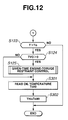
- FIG. 12 is a chart similar to FIG. 10, illustrating a third embodiment of the present invention.
- FIG. 13 is a diagram similar to FIG. 9, showing a fourth embodiment of the present invention.
- FIG. 14 is a chart similar to FIG. 12, illustrating operation of the fourth embodiment
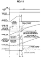
- FIG. 15 is a chart similar to FIG. 11, illustrating operation of the fourth embodiment
- FIG. 16 is a chart similar to FIG. 14, illustrating a fifth embodiment of the present invention.
- FIG. 17 is a chart similar to FIG. 16, illustrating operation of the fifth embodiment.
- a vehicle comprises an engine 10, an automatic transmission 20, a torque converter 30, an electronic control unit (ECU) 50, and a starter generator 60.
- ECU electronice control unit
- the engine 10 is provided with a fuel supply system 11 for supplying fuel to the engine 10, and a chain sprocket 12 connected by a chain 63 to a chain sprocket 62 which is provided to the starter generator 60 through an electromagnetic clutch 61.
- a fuel supply system 11 for supplying fuel to the engine 10
- a chain sprocket 12 connected by a chain 63 to a chain sprocket 62 which is provided to the starter generator 60 through an electromagnetic clutch 61.
- the starter generator 60 is put in engagement with the engine 10 by the electromagnetic clutch 61.
- the automatic transmission 20 is provided with an oil pump 22 which is rotated with the engine 10 for supplying the hydraulic pressure to a hydraulic servo 23, and is branched to directly communicate with a piston chamber of a forward clutch or low clutch L/C through a passage switching solenoid valve 44.
- the ECU 50 inputs signals from an idle-stop switch 1, a brake switch 2, a steering-angle sensor 3, an oil-temperature sensor 4, and a vehicle-speed sensor 5 so as to control operation of the starter generator 60, the solenoid valve 44, and the fuel supply system 11.
- a speed change mechanism 24 comprises a gear-type multiple-speed transmission.
- the multiple-speed transmission includes planetary gears G1, G2, G3, coupling members M1, M2, clutches R/C, H/C, L/C, D/C, brakes L&R/B, 2-4/B, RD/B, one-way clutches L-OWC, RD-OWC, an input shaft or member IN, and an output shaft or member OUT.
- the first planetary gear G1 is a single pinion type planetary gear comprising a first sun gear S1, a first ring gear R1, and a first carrier PC1 for supporting a pinion meshed with the gears S1, R1.
- the second planetary gear G2 is a single pinion type planetary gear comprising a second sun gear S2, a second ring gear R2, and a second carrier PC2 for supporting a pinion meshed with the gears S2, R2.
- the third planetary gear G3 is a single pinion type planetary gear comprising a third sun gear S3, a third ring gear R3, and a third carrier PC3 for supporting a pinion meshed with the gears S3, R3.
- the first coupling member M1 is a member for integrally coupling the first carrier PC1 to the second ring gear R2 through a low clutch L/C.
- the second coupling member M2 is a member for integrally coupling the first ring gear R1 to the second carrier PC2.
- the reverse clutch R/C is engaged at the reverse (R) range to connect the input shaft IN and the first sun gear S1.
- the high clutch H/C is engaged at the third and fourth speeds to connect the input shaft IN and the first carrier PC1.
- the low clutch L/C is engaged at the first, second, and third speeds to connect the first carrier PC1 and the second ring gear R2.
- the direct clutch D/C is engaged at the fifth speed to connect the third carried PC3 and the third sun gear S3.
- the low and reverse brake L&R/B is engaged at the first speed and the R range to fix rotation of the first carrier PC1.
- the 2-4 brake 2-4/B is engaged at the second, fourth, and fifth speeds to fix rotation of the first sun gear S1.
- the reduction brake RD/B is engaged at the first, second, third, and fourth speeds to fix rotation of the third sun gear S3.
- the low one-way clutch L-OWC is actuated when the vehicle is in acceleration at the first speed to fix rotation of the first carrier PC1, and it is not actuated during deceleration.
- the reduction one-way clutch RD-OWC is actuated when the vehicle is in acceleration at the first, second, third, and fourth speeds to fix rotation of the third sun gear S3, and it is not actuated during deceleration.
- the input shaft IN is coupled to the first ring gear R1 so as to input engine torque through the torque converter 30.
- the output shaft OUT is coupled to the third carrier PC3 so as to transfer its output torque to driving wheels through a final gear and the like, not shown.
- Connected to the clutches and the brakes is the hydraulic servo 23 for creating the engagement pressure and the release pressure at each gear ratio.
- FIG. 3 shows a table of engagement operation in the speed change mechanism 24 in the first embodiment.
- a sign ⁇ denotes the engagement state
- a sign ⁇ denotes the state involved in torque transfer at power-on.
- the drive mode includes both a mode selected by shifting a unillustrated select lever at the drive (D) range position, and an automatic-shift mode selected when the automatic transmission has automatic-shift mode and manual-shift mode.
- the hydraulic circuit for supplying the control pressure from the hydraulic servo 23 to the speed change mechanism 24 in the first embodiment.
- the hydraulic circuit comprises oil pump 22 driven by the engine 10, a pressure regulating valve 47 for regulating the discharge pressure of the pump 22 for the line pressure, a line-pressure circuit 40 for supplying the line pressure, first, second and third shift valves 41, 42, 43 for switching the hydraulic circuits, and pilot-pressure circuits 41 b, 42b, 43b for supplying the pilot pressure to the shift valves 41, 42, 43.
- the line-pressure circuit 40 is provided with a bypass passage 45 which communicates with the low clutch L/C immediately upstream thereof.
- the passage switching solenoid valve 44 is arranged on the bypass passage 45 to be switched between the communicating state and the non-communicating state.
- a low-clutch pressure sensor 46 is arranged between the low clutch L/C and the bypass passage 45 to sense the engagement pressure of the low clutch L/C.
- Orifices d1, d2, d3, d4 are arranged immediately upstream of the low clutch L/C, the reduction brake RD/B, the 2-4 brake 2-4/B, and the high clutch H/C, respectively, to prevent the serge pressure which may occur immediately after engagement of the engagement elements, controlling the rise characteristics of the line pressure.
- the passage switching solenoid valve 44 has an equivalent orifice diameter "d" set to be twice or more as large as the diameter of the largest one d2 of the orifices d1, d2, d3, d4. Specifically, referring to FIG.
- a step S101 it is determined whether or not the idle-stop switch 1 is energized, the vehicle speed is zero, the brake switch 2 is turned on, the steering angle is zero, and the range other than the R range is selected. Only if it is determined that all the conditions are met, flow proceeds to a step S102. Otherwise, idle-stop control is cancelled.
- step S102 it is determined whether or not the select position is the drive (D) range. If it is determined that the select position is the D range, flow proceeds to a step S103. Otherwise, flow proceeds to a step S104.
- step S103 it is determined whether or not an oil temperature Toil is higher than a lower-limit temperature Tlow and lower than an upper-limit temperature Thi. If it is determined that the conditions are met, flow proceeds to a step S104. Otherwise, flow comes to an end.
- step S104 processing to stop the engine 10 is carried out.
- step S105 it is determined whether or not the brake switch 2 is turned on. If it is determined that the brake switch 2 is turned on, flow proceeds to a step S106. Otherwise, flow proceeds to a step S107.
- step S106 it is determined whether or not the idle-stop switch 1 is energized. If it is determined that the idle-stop switch 1 is energized, flow proceeds to the step S107. Otherwise, flow returns to the step S104.
- step S107 processing to actuate the starter generator 60 is carried out.
- step S108 it is determined whether or not the select position is the D range. If it is determined that the select position is the D range, flow proceeds to a step S109. Otherwise, flow proceeds to a step S110.
- processing is carried out to turn on the solenoid of the passage switching solenoid valve 44 for switching the bypass passage 45 to the supply side, and to reset a count value of a timer T to zero.
- step S110 processing is carried out to turn off the solenoid of the solenoid valve 44 for switching the bypass passage 45 to the non-supply side.
- an engine rpm Ne is read.
- step S112 it is determined whether or not the engine rpm Ne is greater than a predetermined rpm No. If it is determined that Ne > No, flow proceeds to a step S118. Otherwise, flow proceeds to a step S113.
- a step S114 it is determined whether or not the solenoid of the solenoid valve 44 is turned on. If it is determined that the solenoid of the solenoid valve 44 is turned on, flow proceeds to a step S115. Otherwise, flow returns to the step S111 to continuously actuate the starter generator 60.
- step S115 it is determined whether or not a low-clutch pressure P L/C sensed by the low-clutch sensor 46 is greater than a target pressure Po. If it is determined that P L/C > Po, flow proceeds to a step S117. Otherwise, flow proceeds to a step S116.
- step S116 the timer T is incremented by a time increment DELT, then flow returns to the step S111.
- processing is carried out to tum off the solenoid of the solenoid valve 44 for switching the bypass passage 45 to the non-supply side.
- step S118 processing to stop actuation of the starter generator 60 is carried out.
- a step S119 it is determined whether or not the solenoid of the solenoid valve 44 is turned on. If it is determined that the solenoid of the solenoid valve 44 is turned on, flow proceeds to a step S120. Otherwise, flow proceeds to a step S123.
- step S120 it is determined whether or not the low-clutch pressure P L/C sensed by the low-clutch sensor 46 is greater than target pressure Po. If it is determined that P L/C > Po, flow proceeds to a step S122. Otherwise, flow proceeds to a step S1121.
- step S121 the timer T is incremented by the time increment DELT, then flow returns to the step S120 to continuously timer count until the low-clutch pressure P L/C exceeds target pressure Po.
- step S122 processing is carried out to turn off the solenoid of the solenoid valve 44 for switching the bypass passage 45 to the non-supply side.
- step S123 it is determined whether or not the timer count value T is greater than a predetermined value To. If it is determined that T > To, flow proceeds to a step S124. Otherwise, flow comes to an end.
- step S124 it is determined whether or not a throttle opening TVO is greater than zero, i.e. an accelerator pedal is depressed. If it is determined that TVO > 0, flow proceeds to a step S125. Otherwise, flow comes to an end.
- control is carried out to restrain engine torque during a given time.
- the idle-stop switch 1 is a device through which the driver transmits his/her intention to perform or cancel idle stop. At the point when turning an ignition key, the idle-stop switch 1 is in energization. The reason why it is required that the steering angle is zero is to prohibit idle stop at the time of temporary stop of the running vehicle at right-hand turn and the like, for example.
- the reason why idle-stop control is prohibited at the R range is that the sufficient oil amount cannot be supplied since the oil amount required for achieving completion of engagement is far greater than that required for engagement at the first speed.
- the low clutch L/C and the reduction brake RD/B need supply of the hydraulic pressure.
- the hydraulic pressure is supplied to the reduction brake RD/B, and it needs to be supplied to the low clutch L/C only through the bypass passage 45.
- the hydraulic pressure should also be supplied to the reverse clutch R/C and the low and reverse brake L&R/B, which makes difficult supply of the oil amount required for engagement before engine start.
- the oil temperature Toil is higher than the lower-limit temperature Tlow and lower than the upper-limit temperature Thi.
- the reason why such processing is carried out is that unless the oil temperature is higher than a predetermined value, the viscosity resistance of oil may not allow a predetermined oil amount to be charged before engine complete explosion, and that when the oil temperature is too higher, a decrease in volumetric efficiency of the pump 22 and an increase in leakage at valve parts due to reduction in viscosity resistance may not allow a predetermined oil amount to be charged before engine complete explosion .
- step S110 the passage switching solenoid valve 44 selects ordinary passage.
- processing at the step S111 ⁇ step S112 ⁇ step S113 ⁇ step S114 is carried out repeatedly.
- the starter generator 60 is turned off, then flow proceeds to the step S123.
- step S109 the passage switching solenoid valve 44 selects bypass passage 45 to carry out quick supply of the hydraulic pressure to the low clutch L/C.
- processing at the step S111 ⁇ step S112 ⁇ step S113 ⁇ step S114 ⁇ step S115 ⁇ step S116 is carried out to turn on the solenoid of the passage switching solenoid valve 44 arranged on the bypass passage 45 for communication between the oil pump 22 and the low clutch L/C immediately upstream thereof, achieving switching to the communicating state.
- oil which has been supplied to the low clutch UC is discharged through the hydraulic passage, having reduced hydraulic pressure.
- the low clutch L/C is disengaged which is to be engaged during running at the first speed, and thus needs to be supplied with the hydraulic pressure.
- a count value of the timer T for measuring a time from start of the starter generator 60 is reset to zero.
- FIG. 8 shows oil flow immediately after driving the oil pump 22. Since sufficient pilot pressure is not supplied to actuate the shift valves 41, 42, 43, oil flows through the hatched section in the hydraulic circuit shown in FIG. 8. At that time, since the passage switching solenoid valve 44 is in the communicating state, oil is also supplied to the low clutch L/C.
- FIG. 9 shows oil flow after supplying the pilot pressure to the shift valves 41, 42, 43.
- Ne is greater than predetermined rpm No. If it is determined whether or not the engine 10 has complete explosion. If it is determined that Ne ⁇ No, i.e. the engine 10 does not have completer explosion, flow proceeds to the step S113 where the rotation rise speed dNe/dT of the starter generator 60 is set at predetermined value So to continuously crank the engine 10. Then, it is determined whether or not the low-clutch pressure P L/C sensed by the low-clutch pressure sensor 46 reaches target pressure Po. If it is determined that the low-clutch pressure P L/C does not reaches target pressure Po, the timer T is incremented to obtain a timer count value T + DELT, and the above processing is carried out repeatedly.
- the low-clutch pressure P L/C is sensed by the low-clutch pressure sensor 46.
- the passage switching solenoid valve 44 can be put in the non-communicating state. And when required engagement pressure is secured, further oil supply is not needed through the bypass passage 45. It is understood that detection of the low-clutch pressure P L/C allows achievement of the non-communicating state of the bypass passage 45 at the optimum timing, resulting in efficient use of the discharge amount of the oil pump 22.
- Determination of a time until the low-clutch pressure is secured after engine restart At the step S123, it is determined whether or not the timer count value T is greater than predetermined value To. If it is determined that T ⁇ To, it is determined that low-clutch pressure P L/C can be secured smoothly, and flow comes to an end.
- FIG. 7 is a time chart with/without engine-torque restraint control when the timer count value T is greater than predetermined value To.
- the engine rpm Ne without engine-torque restraint control is shown by dotted line.
- greater time count value T shows a case where the engine 10 has complete explosion, sufficient discharge capacity of the oil pump 22 is secured, and engine torque is increased.
- the low-clutch pressure P L/C is secured finally, so that the low clutch L/C is engaged with input torque being greater, producing an engagement shock which will cause a vertical variation in longitudinal acceleration (G) of the vehicle.
- control is carried out to restrain engine torque during a given time, providing engine torque roughly equal to that immediately after engine complete explosion, achieving engagement of the low clutch L/C.
- This allows achievement of smooth start acceleration along the longitudinal G shown by solid line in FIG. 7. It is desirable that a time for restraining engine torque corresponds roughly to a time required from engine initial explosion to the low-clutch pressure P L/C reaching target pressure Po.
- a torque reduction command is provided to the ECU 50, even if the throttle opening TVO is detected, until the low-clutch pressure P L/C reaches target pressure Po.
- a torque reduction command is provided to reduce input torque to the low clutch L/C. This allows prevention of an engagement shock to be produced at engine restart by engagement of the low clutch L/C with engine rotation highly increased by depressing the accelerator pedal in the neutral state as it were.
- the low-clutch pressure P L/C is sensed by the low-clutch pressure sensor 46.
- the passage switching solenoid valve 44 can be put in the non-communicating state. And when required engagement pressure is secured, further oil supply is not needed through the bypass passage 45. It is understood that detection of the low-clutch pressure P L/C allows achievement of the non-communicating state of the bypass passage 45 at the optimum timing, resulting in efficient use of the discharge amount of the oil pump 22.
- FIG. 10 there is shown second embodiment of the present invention which is essentially the same as the first embodiment shown in FIGS. 5 and 6 except processing at steps S201-S204.
- control is carried out to delay the engine initial explosion timing.
- a value obtaining by adding ⁇ T the predetermined time To for determining a timer count value at the step S123 is set as a new predetermined time To.
- step S203 it is determined whether or not the new predetermine time To is greater than a maximum value Tomax. If it is determined that To ⁇ Tomax, flow comes to and end, whereas if it is determined that To > Tomax, flow proceeds to the step S204.
- the maximum time Tomax is set as predetermined time To.
- Shock due to timing lag Referring to FIG. 11, a time chart is shown by dotted line, wherein before learning, the timing from engine initial explosion to the forward-clutch or low-clutch pressure reaching target pressure Po is lagged to produce a shock.
- the starter generator 60 is driven to crank the engine 10. Then, the timer T is reset to start increment. During a period of time t1 to time t2, cranking of the starter generator 60 causes increasing of the engine rpm Ne, and driving of the oil pump 22. Moreover, due to the D range selected, the low-clutch pressure P L/C is supplied through the bypass passage 44 switched by the passage switching solenoid valve 45, which increases gradually.
- the engine rpm Ne reaches a predetermined rpm.
- the ECU 50 provides an ignition signal to the engine 10, carrying out initial explosion.
- the engine rpm Ne reaches a complete-explosion determination rpm No, tuning the starter generator 60 off. After complete explosion, the engine rpm Ne increases by self-rotation.
- timer count is carried out.
- a desirable engine rpm causing no start shock or the like when the low-clutch pressure P L/C reaches predetermined pressure Po is given by Ne1
- a desirable time required from output of an engine-restart command to achievement of the predetermined pressure Po is given by predetermined time To.
- the predetermined time To is determined in accordance with an engine initial timing set by the ECU 50. (Suppose that an increasing manner of the engine rpm Ne after initial explosion followed by complete explosion and self-rotation is roughly constant. If too much time elapses after initial explosion, it can be estimated that an excessive increase in the engine rpm Ne occurs. Thus, engagement of the low clutch L/C is desirable within a time period that an excessive increase in the engine rpm Ne does not occur).
- the low-clutch pressure P L/C has a pressure P1 smaller than the predetermined pressure Po, so that the low clutch L/C cannot be engaged yet.
- the engine rpm Ne increases with a lapse of time, and becomes equal to Ne2 when the low-clutch pressure P L/C reaches predetermined pressure Po (time t5). Specifically, the discharge pressure of the oil pump 22 increases with an increase in the engine rpm Ne. However, since longer time t5 is required for the low-clutch pressure P L/C to reach predetermined pressure Po due to secular deterioration and the like, the engine rpm Ne increases excessively (Ne2). Thus, torque input from the engine 10 to the low clutch L/C becomes greater, having possibility of occurrence of a start shock as seen from the longitudinal G shown by dotted line in FIG. 11.
- Engine initial explosion timing delay control A command is provided to the ECU 50 to delay the engine initial explosion timing by ⁇ T. Then, the engine rpm Ne is maintained at the cranking-state engine rpm by the starter generator 60 up to time t20, resulting in a ⁇ T increase in the cranking-state engine rpm. During this period, the hydraulic pressure is supplied from the oil pump 22 to the low clutch L/C, so that a time required from engine initial explosion (time t20) to the low-clutch pressure P L/C reaching predetermined pressure Po (t20-t30 ⁇ t2-t4) becomes shorter.
- the engine rpm Ne is equal to the desirable engine rpm Ne1 for engagement of the low clutch L/C, having no occurrence of an excessive increase in torque input to the low clutch L/C due to excessively increased engine rpm Ne. This allows execution of smooth start control.
- the predetermined time To used for comparison of a timer count value is increased by ⁇ T from the next time.
- the predetermined time To is provided with maximum or limiter value Tomax, preventing engine start from being too slow.
- FIG. 12 there is shown third embodiment of the present invention which is essentially the same as the first embodiment shown in FIGS. 5 and 6 except processing at steps S301 and S302.
- an oil temperature Toil0 is read.
- the upper-limit value Thi used for determination of the oil temperature Toil at the step S103 is updated to oil temperature Toil0 read at the step S301.
- FIGS. 13 and 14 there is shown fourth embodiment of the present invention which is essentially the same as the first embodiment shown in FIGS. 4-6 except no arrangement of the low-clutch pressure sensor 46 for sensing the engagement pressure of the low clutch L/C, and processing at steps S401-S411.
- the engine rpm Ne is read.
- step S402 it is determined whether or not the engine rpm Ne is greater than predetermined engine rpm No. If it is determined that Ne > No, flow proceeds to the step S406, whereas if it is determined that Ne ⁇ No, flow proceeds to the step S403.
- step S404 it is determined whether or not the solenoid of the passage switching solenoid valve 44 is turned on. If it is determined that the solenoid of the solenoid valve 44 is turned on, flow proceeds to the step S405. Otherwise, flow returns to the step S401 to continuously actuate the starter generator 60.
- step S406 processing to stop actuation of the starter generator 60 is carried out.
- step S407 it is determined whether or not the solenoid of the solenoid valve 44 is turned on. If it is determined that the solenoid of the solenoid valve 44 is turned on, flow proceeds to the step S408. Otherwise, flow proceeds to the step S123.
- a turbine rpm Nt is read to compute a turbine rpm variation ⁇ Nt, then flow proceeds to the step S409.
- step S409 it is determined whether or not the turbine rpm variation ⁇ Nt is smaller than zero. If it is determined that ⁇ Nt ⁇ 0, flow proceeds to the step S411, whereas If it is determined that ⁇ Nt > 0, flow proceeds to the step S410.
- the timer T is incremented by the time increment DELT, then flow returns to the step S408 to continuously timer count until the turbine rpm variation ⁇ Nt becomes negative.
- processing is carried out to turn off the solenoid of the solenoid valve 44 for switching the bypass passage 45 to the non-supply side.
- FIG. 15 is a time chart when combining idle-stop control in the fourth embodiment with engine initial explosion timing delay control in the second embodiment.
- the contents of control are essentially the same as those described above except that it is determined whether or not the low-clutch pressure P L/C reaches predetermined pressure Po in accordance with the turbine rpm Nt.
- the difference in determination of the low-clutch pressure P L/C is described.
- the timer T is incremented from time t1, and the engine 10 is put in complete explosion by cranking of the starter generator 60.
- the starter generator 60 is turned off. And it is determined whether or not the D range is selected, and the passage switching solenoid valve 44 selects bypass passage 45. If it is determined that solenoid valve 44 selects bypass passage 45, the turbine rpm Nt is read to compute the turbine rpm variation ⁇ Nt.
- the engine 10 is cranked by the starter generator 60.
- the turbine rpm Nt varies. But when it is determined that engine complete explosion is achieved (at time t3 before learning, and at time t30 after learning), engine output torque is stabilized up to a point, which is input to the automatic transmission 20 to rotate the turbine.
- the low clutch L/C receives hydraulic pressure through the bypass passage 45, producing a certain engagement force.
- the low clutch L/C has one side connected to the turbine and another side connected to the driving wheels. Since the vehicle starts from a standstill, a fixing force resulting from inertial force acts on the driving wheels. Through the low clutch L/C, the inertia force causes the turbine rpm Nt to drop once (at time t4 before learning, and at time t40 after learning).
- the low clutch L/C secures a certain engagement force, i.e. so-called pre-charge is completed. Switching from the bypass passage 45 to the ordinary passage at that timing allows smooth execution of switching.
- FIGS. 16 and 17 there is shown fifth embodiment of the present invention which is essentially the same as the first embodiment except processing at steps S104a-S104e, S123a, and S125a.
- step S104a counting of the timer ⁇ is started.
- a predetermined automatic restart time Ts is set at a time shorter than a previous timer value ⁇ by a predetermined value ⁇ .
- step S104d it is determined whether or not the timer ⁇ is greater than the predetermined automatic restart time Ts. If it is determined that ⁇ ⁇ Ts, flow proceeds to the step S105, whereas if it is determined that ⁇ > Ts, flow proceeds to the step S104e.
- the automatic restart flag F is reset to zero.
- the automatic restart flag F is set at 1.
- increment of the timer ⁇ is started to measure an engine stop duration. If achievement of the engagement pressure of the low clutch L/C is delayed to carry out given-time engine-torque restraint control, the automatic restart flag F is set at 1 at the step S125a due to occurrence of the conditions of prohibiting smooth start.
- the predetermined automatic restart time Ts is set at a time ⁇ - ⁇ shorter than an engine stop duration at previous given-time engine-torque restraint control by a predetermined value at the step S104c. If a timer count value becomes greater than Ts, the engine 10 is restarted regardless of the state of the brake switch 2 and the idle-stop switch 1. Thus, due to longer idle-stop duration, oil within the hydraulic passages for the low clutch L/C is discharged completely, allowing prevention of a time required for achievement of the predetermined low-clutch pressure Po from being delayed.
- the present invention is not limited thereto, and various changes and modifications can be made without departing from the scope of the present invention.
- the present invention is applicable to not only to the low clutch, but also to any of other forward engagement elements of the automatic transmission.
- the invention is applied to the forward engagement element of the gear-type multiple-speed automatic transmission.
- the invention can be applied to the forward engagement element of a continuously variable transmission (CVT).
- CVT continuously variable transmission
Abstract
Description
- The present invention relates to a hydraulic system for an automatic transmission, and more particularly, to a hydraulic system for an automatic transmission for a vehicle having idle-stop control for stopping engine idle at a standstill of the running vehicle.
- In recent years, idle-stop vehicles are already operational wherein when the running vehicle comes into a standstill, and predetermined stop conditions are formed, an engine is automatically stopped to achieve fuel savings, a reduction in exhaust emission or noises and the like. With such vehicle, when the engine is stopped, a main pump driven by the engine is stopped, so that oil supplied to a forward clutch or engagement element of an automatic transmission is drawn from a hydraulic passage, lowering the hydraulic pressure. As a result, when the engine is restarted, the forward clutch to be engaged at forward running releases from its engagement state. Thus, if the forward clutch is not engaged quickly at engine restart, an accelerator pedal is depressed in the neutral state as it were, which may produce an engagement shock by engagement of the forward clutch with engine rotation highly increased.
- The technique for solving the above inconvenience is proposed in U.S. Patent No. 6,093,974. This technique adopts a system for starting an oil supply for engaging a forward clutch concurrently with engine restart. In order to obtain engagement of the forward clutch as fast as possible, quick pressure increase control for oil is temporarily carried out during a predetermined time when supplying oil. The reference discloses as quick pressure increase control a technique for reducing a time required for oil supply through a hydraulic passage with higher passage resistance and a technique for setting a target control pressure of a solenoid for adjusting the line pressure to a value higher than an ordinary value.
- However, the above earlier art raises the following problem. When the engagement element includes a multiple disk clutch, for example, its facing will be thinned due to degradation with time. Such reduction in thickness of the facing leads to an increase in pre-charge time corresponding to a piston stroke. Thus, even if quick pressure increase control is carried out during a predetermined time, torque input from the engine is increased without sufficient engagement pressure being secured, raising a problem of having highly increased engine rotation. Moreover, even without having highly increased engine rotation, the forward clutch is engaged with torque input from the engine being greater, raising a problem of producing a start shock.
- It is, therefore, an object of the present invention to provide a hydraulic system for an automatic transmission for a vehicle having idle-stop control, which allows smooth running of the vehicle during execution of idle-stop control.
- The present invention provides generally an automatic transmission (20) for a vehicle having idle-stop control means for controlling idle start and idle stop of an engine (10) in accordance with predetermined idle-stop conditions during idle running of the vehicle, characterized in that it comprises means for detecting a value equivalent to an engagement pressure (PL/C) of a forward engagement element (L/C), and means for determining if the equivalent value detected after a lapse of a predetermined time from engine restart reaches a predetermined value, wherein if the determining means determine that the equivalent value does not reach the predetermined value, the idle-stop control means provide a torque reduction command to an ECU (50), regardless of a throttle opening (TVO), until the equivalent value reaches the predetermined value.
- An aspect of the present invention is to provide a method of controlling an automatic transmission (20) for a vehicle having idle-stop control means for controlling idle start and idle stop of an engine (10) in accordance with predetermined idle-stop conditions during idle running of the vehicle, characterized in that it comprises detecting a value equivalent to an engagement pressure (PL/C) of a forward engagement element (L/C), and determining if the equivalent value detected after a lapse of a predetermined time from engine restart reaches a predetermined value, wherein if it is determined that the equivalent value does not reach the predetermined value, the idle-stop control means provide a torque reduction command to an ECU (50), regardless of a throttle opening (TVO), until the equivalent value reaches the predetermined value.
- The other objects and features of the present invention will become apparent from the following description with reference to the accompanying drawings, wherein:
- FIG. 1 is a block diagram showing a control system for a vehicle provided with a hydraulic system for an automatic transmission embodying the present invention;
- FIG. 2 is a schematic drawing illustrating a multiple-speed transmission or a speed change mechanism;
- FIG. 3 is a table showing engagement of engagement elements in the multiple-speed transmission;
- FIG. 4 is a diagram illustrating a hydraulic circuit in a first embodiment;
- FIG. 5 is a flowchart illustrating operation of the first embodiment;
- FIG. 6 is a chart similar to FIG. 5, illustrating operation of the first embodiment;
- FIG. 7 is a time chart illustrating operation of the first embodiment;
- FIG. 8 is a diagram similar to FIG. 4, showing oil flow immediately after engine restart in the first embodiment;
- FIG. 9 is a diagram similar to FIG. 8, showing oil flow after supplying the pilot pressure in the first embodiment;
- FIG. 10 is a chart similar to FIG. 6, illustrating a second embodiment of the present invention;
- FIG. 11 is a chart similar to FIG. 7, illustrating operation of the second embodiment;
- FIG. 12 is a chart similar to FIG. 10, illustrating a third embodiment of the present invention;
- FIG. 13 is a diagram similar to FIG. 9, showing a fourth embodiment of the present invention;
- FIG. 14 is a chart similar to FIG. 12, illustrating operation of the fourth embodiment;
- FIG. 15 is a chart similar to FIG. 11, illustrating operation of the fourth embodiment;
- FIG. 16 is a chart similar to FIG. 14, illustrating a fifth embodiment of the present invention; and
- FIG. 17 is a chart similar to FIG. 16, illustrating operation of the fifth embodiment.
- Referring to the drawings, a description is made with regard to a hydraulic system for an automatic transmission for a vehicle having idle-stop control embodying the present invention.
- Referring to FIG. 1, a vehicle comprises an engine 10, an automatic transmission 20, a torque converter 30, an electronic control unit (ECU) 50, and a starter generator 60.
- The engine 10 is provided with a fuel supply system 11 for supplying fuel to the engine 10, and a chain sprocket 12 connected by a chain 63 to a chain sprocket 62 which is provided to the starter generator 60 through an electromagnetic clutch 61. When serving as a starter of the engine 10, a generator in deceleration, and a generator for generating power in accordance with the battery storage state, the starter generator 60 is put in engagement with the engine 10 by the electromagnetic clutch 61.
- The automatic transmission 20 is provided with an oil pump 22 which is rotated with the engine 10 for supplying the hydraulic pressure to a hydraulic servo 23, and is branched to directly communicate with a piston chamber of a forward clutch or low clutch L/C through a passage switching solenoid valve 44.
- The ECU 50 inputs signals from an idle-stop switch 1, a brake switch 2, a steering-angle sensor 3, an oil-temperature sensor 4, and a vehicle-speed sensor 5 so as to control operation of the starter generator 60, the solenoid valve 44, and the fuel supply system 11.
- In the first embodiment, a speed change mechanism 24 comprises a gear-type multiple-speed transmission. Referring to FIG. 2, the multiple-speed transmission includes planetary gears G1, G2, G3, coupling members M1, M2, clutches R/C, H/C, L/C, D/C, brakes L&R/B, 2-4/B, RD/B, one-way clutches L-OWC, RD-OWC, an input shaft or member IN, and an output shaft or member OUT.
- The first planetary gear G1 is a single pinion type planetary gear comprising a first sun gear S1, a first ring gear R1, and a first carrier PC1 for supporting a pinion meshed with the gears S1, R1. The second planetary gear G2 is a single pinion type planetary gear comprising a second sun gear S2, a second ring gear R2, and a second carrier PC2 for supporting a pinion meshed with the gears S2, R2. The third planetary gear G3 is a single pinion type planetary gear comprising a third sun gear S3, a third ring gear R3, and a third carrier PC3 for supporting a pinion meshed with the gears S3, R3.
- The first coupling member M1 is a member for integrally coupling the first carrier PC1 to the second ring gear R2 through a low clutch L/C. The second coupling member M2 is a member for integrally coupling the first ring gear R1 to the second carrier PC2.
- The reverse clutch R/C is engaged at the reverse (R) range to connect the input shaft IN and the first sun gear S1. The high clutch H/C is engaged at the third and fourth speeds to connect the input shaft IN and the first carrier PC1. The low clutch L/C is engaged at the first, second, and third speeds to connect the first carrier PC1 and the second ring gear R2. The direct clutch D/C is engaged at the fifth speed to connect the third carried PC3 and the third sun gear S3.
- The low and reverse brake L&R/B is engaged at the first speed and the R range to fix rotation of the first carrier PC1. The 2-4 brake 2-4/B is engaged at the second, fourth, and fifth speeds to fix rotation of the first sun gear S1. The reduction brake RD/B is engaged at the first, second, third, and fourth speeds to fix rotation of the third sun gear S3. The low one-way clutch L-OWC is actuated when the vehicle is in acceleration at the first speed to fix rotation of the first carrier PC1, and it is not actuated during deceleration. The reduction one-way clutch RD-OWC is actuated when the vehicle is in acceleration at the first, second, third, and fourth speeds to fix rotation of the third sun gear S3, and it is not actuated during deceleration.
- The input shaft IN is coupled to the first ring gear R1 so as to input engine torque through the torque converter 30. The output shaft OUT is coupled to the third carrier PC3 so as to transfer its output torque to driving wheels through a final gear and the like, not shown. Connected to the clutches and the brakes is the hydraulic servo 23 for creating the engagement pressure and the release pressure at each gear ratio.
- Next, speed change operation is described. FIG. 3 shows a table of engagement operation in the speed change mechanism 24 in the first embodiment. In FIG. 3, a sign ○ denotes the engagement state, and a sign Δ denotes the state involved in torque transfer at power-on. Note that the drive mode includes both a mode selected by shifting a unillustrated select lever at the drive (D) range position, and an automatic-shift mode selected when the automatic transmission has automatic-shift mode and manual-shift mode.
- Referring to FIG. 4, there is shown a hydraulic circuit for supplying the control pressure from the hydraulic servo 23 to the speed change mechanism 24 in the first embodiment. The hydraulic circuit comprises oil pump 22 driven by the engine 10, a pressure regulating valve 47 for regulating the discharge pressure of the pump 22 for the line pressure, a line-pressure circuit 40 for supplying the line pressure, first, second and third shift valves 41, 42, 43 for switching the hydraulic circuits, and pilot-pressure circuits 41 b, 42b, 43b for supplying the pilot pressure to the shift valves 41, 42, 43. The line-pressure circuit 40 is provided with a bypass passage 45 which communicates with the low clutch L/C immediately upstream thereof. The passage switching solenoid valve 44 is arranged on the bypass passage 45 to be switched between the communicating state and the non-communicating state. A low-clutch pressure sensor 46 is arranged between the low clutch L/C and the bypass passage 45 to sense the engagement pressure of the low clutch L/C.
- Orifices d1, d2, d3, d4 are arranged immediately upstream of the low clutch L/C, the reduction brake RD/B, the 2-4 brake 2-4/B, and the high clutch H/C, respectively, to prevent the serge pressure which may occur immediately after engagement of the engagement elements, controlling the rise characteristics of the line pressure. The passage switching solenoid valve 44 has an equivalent orifice diameter "d" set to be twice or more as large as the diameter of the largest one d2 of the orifices d1, d2, d3, d4. Specifically, referring to FIG. 8, when sufficient pilot pressure is not supplied to the shift valves 41, 42, 43, oil is supplied to the reduction bake RD/B, the 2-4 brake 2-4/B, and the high clutch H/C, the amounts of which are proportional to the square of the diameters of the orifices d2, d3, d4 (d2 > d3 > d4) arranged on the hydraulic passages for the devices. When oil is supplied to the low clutch UC through the bypass passage 45, the quantity Q of oil supplied to the low clutch L/C is given by:
- Referring to FIGS. 5 and 6, the contents of idle-stop control in the first embodiment are described.
- At a step S101, it is determined whether or not the idle-stop switch 1 is energized, the vehicle speed is zero, the brake switch 2 is turned on, the steering angle is zero, and the range other than the R range is selected. Only if it is determined that all the conditions are met, flow proceeds to a step S102. Otherwise, idle-stop control is cancelled.
- At the step S102, it is determined whether or not the select position is the drive (D) range. If it is determined that the select position is the D range, flow proceeds to a step S103. Otherwise, flow proceeds to a step S104.
- At the step S103, it is determined whether or not an oil temperature Toil is higher than a lower-limit temperature Tlow and lower than an upper-limit temperature Thi. If it is determined that the conditions are met, flow proceeds to a step S104. Otherwise, flow comes to an end.
- At the step S104, processing to stop the engine 10 is carried out.
- At a step S105, it is determined whether or not the brake switch 2 is turned on. If it is determined that the brake switch 2 is turned on, flow proceeds to a step S106. Otherwise, flow proceeds to a step S107.
- At the step S106, it is determined whether or not the idle-stop switch 1 is energized. If it is determined that the idle-stop switch 1 is energized, flow proceeds to the step S107. Otherwise, flow returns to the step S104.
- At the step S107, processing to actuate the starter generator 60 is carried out.
- At a step S108, it is determined whether or not the select position is the D range. If it is determined that the select position is the D range, flow proceeds to a step S109. Otherwise, flow proceeds to a step S110.
- At the step S109, processing is carried out to turn on the solenoid of the passage switching solenoid valve 44 for switching the bypass passage 45 to the supply side, and to reset a count value of a timer T to zero.
- At the step S110, processing is carried out to turn off the solenoid of the solenoid valve 44 for switching the bypass passage 45 to the non-supply side.
- At a step S111, an engine rpm Ne is read.
- At a step S112, it is determined whether or not the engine rpm Ne is greater than a predetermined rpm No. If it is determined that Ne > No, flow proceeds to a step S118. Otherwise, flow proceeds to a step S113.
- At the step S113, processing is carried out to actuate the starter generator 60 at a rotation rise speed dNe/dT = So.
- At a step S114, it is determined whether or not the solenoid of the solenoid valve 44 is turned on. If it is determined that the solenoid of the solenoid valve 44 is turned on, flow proceeds to a step S115. Otherwise, flow returns to the step S111 to continuously actuate the starter generator 60.
- At the step S115, it is determined whether or not a low-clutch pressure PL/C sensed by the low-clutch sensor 46 is greater than a target pressure Po. If it is determined that PL/C > Po, flow proceeds to a step S117. Otherwise, flow proceeds to a step S116.
- At the step S116, the timer T is incremented by a time increment DELT, then flow returns to the step S111.
- At the step S117, processing is carried out to tum off the solenoid of the solenoid valve 44 for switching the bypass passage 45 to the non-supply side.
- At the step S118, processing to stop actuation of the starter generator 60 is carried out.
- At a step S119, it is determined whether or not the solenoid of the solenoid valve 44 is turned on. If it is determined that the solenoid of the solenoid valve 44 is turned on, flow proceeds to a step S120. Otherwise, flow proceeds to a step S123.
- At the step S120, it is determined whether or not the low-clutch pressure PL/C sensed by the low-clutch sensor 46 is greater than target pressure Po. If it is determined that PL/C > Po, flow proceeds to a step S122. Otherwise, flow proceeds to a step S1121.
- At the step S121, the timer T is incremented by the time increment DELT, then flow returns to the step S120 to continuously timer count until the low-clutch pressure PL/C exceeds target pressure Po.
- At the step S122, processing is carried out to turn off the solenoid of the solenoid valve 44 for switching the bypass passage 45 to the non-supply side.
- At the step S123, it is determined whether or not the timer count value T is greater than a predetermined value To. If it is determined that T > To, flow proceeds to a step S124. Otherwise, flow comes to an end.
- At the step S124, it is determined whether or not a throttle opening TVO is greater than zero, i.e. an accelerator pedal is depressed. If it is determined that TVO > 0, flow proceeds to a step S125. Otherwise, flow comes to an end.
- At the step S125, control is carried out to restrain engine torque during a given time.
- Specifically, if a driver wants idle-stop control, the vehicle is at a standstill, a brake pedal is depressed, the steering angle is zero, and the R range is not selected, the engine 10 is stopped. The idle-stop switch 1 is a device through which the driver transmits his/her intention to perform or cancel idle stop. At the point when turning an ignition key, the idle-stop switch 1 is in energization. The reason why it is required that the steering angle is zero is to prohibit idle stop at the time of temporary stop of the running vehicle at right-hand turn and the like, for example.
- The reason why idle-stop control is prohibited at the R range is that the sufficient oil amount cannot be supplied since the oil amount required for achieving completion of engagement is far greater than that required for engagement at the first speed. Specifically, as shown in the engagement table in FIG. 3, at the first speed, the low clutch L/C and the reduction brake RD/B need supply of the hydraulic pressure. Even in the state where the shift valves 41, 42, 43 do not switch the hydraulic passages, the hydraulic pressure is supplied to the reduction brake RD/B, and it needs to be supplied to the low clutch L/C only through the bypass passage 45. However, at the R range, the hydraulic pressure should also be supplied to the reverse clutch R/C and the low and reverse brake L&R/B, which makes difficult supply of the oil amount required for engagement before engine start.
- Then, it is determined whether or not the oil temperature Toil is higher than the lower-limit temperature Tlow and lower than the upper-limit temperature Thi. The reason why such processing is carried out is that unless the oil temperature is higher than a predetermined value, the viscosity resistance of oil may not allow a predetermined oil amount to be charged before engine complete explosion, and that when the oil temperature is too higher, a decrease in volumetric efficiency of the pump 22 and an increase in leakage at valve parts due to reduction in viscosity resistance may not allow a predetermined oil amount to be charged before engine complete explosion .
- Subsequently, when the brake pedal is released, it is determined that the driver has his/her intention to start the engine 10. Moreover, even with the brake pedal depressed, if it is shown that the idle-stop switch 1 is not energized, it is determined that the driver has his/her intention to start the engine 10. This determination aims to prevent the situation of impossible use of an air conditioner and the like due to a load applied to the battery when the engine 10 is stopped for idle stop, for example. That is, when feeling that the temperature in the cabin is high, the driver can cancel idle-stop control, allowing execution of control in further conformity with his/her intention. With this, the starter generator 60 is actuated to supply the hydraulic pressure to the line-pressure passage 40.
- When the driver selects the range other than the D range: It is a case where the driver has no intention to start the vehicle, wherein at the step S110, the passage switching solenoid valve 44 selects ordinary passage. Thus, processing at the step S111 → step S112 → step S113 → step S114 is carried out repeatedly. When the engine rpm Ne reaches predetermined rpm No, the starter generator 60 is turned off, then flow proceeds to the step S123. At the step S123, it is determined whether or not the timer count value T is greater than predetermined value To, but the timer T is not incremented, and thus flow comes to an end.
- When the driver selects the D range: It is a case where the driver has his/her intention to start the vehicle, wherein at the step S109, the passage switching solenoid valve 44 selects bypass passage 45 to carry out quick supply of the hydraulic pressure to the low clutch L/C. Thus, processing at the step S111 → step S112 → step S113 → step S114 → step S115 → step S116 is carried out to turn on the solenoid of the passage switching solenoid valve 44 arranged on the bypass passage 45 for communication between the oil pump 22 and the low clutch L/C immediately upstream thereof, achieving switching to the communicating state. Specifically, at engine stop, oil which has been supplied to the low clutch UC is discharged through the hydraulic passage, having reduced hydraulic pressure. As a result, at engine restart, the low clutch L/C is disengaged which is to be engaged during running at the first speed, and thus needs to be supplied with the hydraulic pressure. Moreover, at the same time, a count value of the timer T for measuring a time from start of the starter generator 60 is reset to zero.
- Then, at engine restart, the starter generator 60 rotates the engine 10, driving the oil pump 22. FIG. 8 shows oil flow immediately after driving the oil pump 22. Since sufficient pilot pressure is not supplied to actuate the shift valves 41, 42, 43, oil flows through the hatched section in the hydraulic circuit shown in FIG. 8. At that time, since the passage switching solenoid valve 44 is in the communicating state, oil is also supplied to the low clutch L/C. FIG. 9 shows oil flow after supplying the pilot pressure to the shift valves 41, 42, 43.
- In accordance with determination whether or not the engine rpm Ne is greater than predetermined rpm No, it is determined whether or not the engine 10 has complete explosion. If it is determined that Ne ≤ No, i.e. the engine 10 does not have completer explosion, flow proceeds to the step S113 where the rotation rise speed dNe/dT of the starter generator 60 is set at predetermined value So to continuously crank the engine 10. Then, it is determined whether or not the low-clutch pressure PL/C sensed by the low-clutch pressure sensor 46 reaches target pressure Po. If it is determined that the low-clutch pressure PL/C does not reaches target pressure Po, the timer T is incremented to obtain a timer count value T + DELT, and the above processing is carried out repeatedly.
- When the low-clutch pressure is secured at actuation of the starter generator: When the engine rpm Ne does not exceed predetermined rpm No, the starter generator 60 is actuated continuously. However, if the passage switching solenoid valve 44 is in the communicating state, and that the low-clutch pressure PL/C reaches target pressure Po, the solenoid valve 44 is put in the non-communicating state, and the starter generator 60 is actuated until the engine rpm Ne reaches predetermined rpm No.
- Specifically, the low-clutch pressure PL/C is sensed by the low-clutch pressure sensor 46. Thus, even at actuation of the starter generator 60, if the low-clutch pressure PL/C reaches target pressure Po, the passage switching solenoid valve 44 can be put in the non-communicating state. And when required engagement pressure is secured, further oil supply is not needed through the bypass passage 45. It is understood that detection of the low-clutch pressure PL/C allows achievement of the non-communicating state of the bypass passage 45 at the optimum timing, resulting in efficient use of the discharge amount of the oil pump 22.
- When the low-clutch pressure is secured after stopping the starter generator: When the driver selects the D range to actuate the starter generator 60, and that the engine rpm Ne reaches predetermined rpm No before the low-clutch pressure PL/C reaches target pressure Po, processing at the step S118 → step S119 → step S120 → step S121 is carried out. At that time, increment of the timer T which has started after actuation of the starter generator 60 is continuously carried out to measure a time until the low-clutch pressure PL/C is secured. When the low-clutch pressure PL/C reaches target pressure Po, the solenoid of the passage switching solenoid valve 44 is turned off.
- Determination of a time until the low-clutch pressure is secured after engine restart: At the step S123, it is determined whether or not the timer count value T is greater than predetermined value To. If it is determined that T ≤ To, it is determined that low-clutch pressure PL/C can be secured smoothly, and flow comes to an end.
- On the other hand, if it is determined that T > To, flow proceeds to the step S124. If it is determined that the accelerator pedal is depressed, flow proceeds to the step S125 where control is carried out to restrain engine torque during a given time. FIG. 7 is a time chart with/without engine-torque restraint control when the timer count value T is greater than predetermined value To. Referring to FIG. 7, the engine rpm Ne without engine-torque restraint control is shown by dotted line. In such a way, greater time count value T shows a case where the engine 10 has complete explosion, sufficient discharge capacity of the oil pump 22 is secured, and engine torque is increased. In this state, the low-clutch pressure PL/C is secured finally, so that the low clutch L/C is engaged with input torque being greater, producing an engagement shock which will cause a vertical variation in longitudinal acceleration (G) of the vehicle.
- Then, at the step S125, control is carried out to restrain engine torque during a given time, providing engine torque roughly equal to that immediately after engine complete explosion, achieving engagement of the low clutch L/C. This allows achievement of smooth start acceleration along the longitudinal G shown by solid line in FIG. 7. It is desirable that a time for restraining engine torque corresponds roughly to a time required from engine initial explosion to the low-clutch pressure PL/C reaching target pressure Po.
- As described above, in the first embodiment, if, at engine restart after idle stop, it is determined that the low-clutch pressure PL/C does not reach target pressure Po, a torque reduction command is provided to the ECU 50, even if the throttle opening TVO is detected, until the low-clutch pressure PL/C reaches target pressure Po. Specifically, even when the accelerator pedal is depressed at engine restart, i.e. the driver has his/her intention to start the vehicle, if sufficient low-clutch pressure PL/C is not obtained, a torque reduction command is provided to reduce input torque to the low clutch L/C. This allows prevention of an engagement shock to be produced at engine restart by engagement of the low clutch L/C with engine rotation highly increased by depressing the accelerator pedal in the neutral state as it were.
- Moreover, the low-clutch pressure PL/C is sensed by the low-clutch pressure sensor 46. Thus, even at actuation of the starter generator 60, if the low-clutch pressure PL/C reaches target pressure Po, the passage switching solenoid valve 44 can be put in the non-communicating state. And when required engagement pressure is secured, further oil supply is not needed through the bypass passage 45. It is understood that detection of the low-clutch pressure PL/C allows achievement of the non-communicating state of the bypass passage 45 at the optimum timing, resulting in efficient use of the discharge amount of the oil pump 22.
- Referring to FIG. 10, there is shown second embodiment of the present invention which is essentially the same as the first embodiment shown in FIGS. 5 and 6 except processing at steps S201-S204.
- At the step S201, control is carried out to delay the engine initial explosion timing.
- At the step S202, a value obtaining by adding ΔT the predetermined time To for determining a timer count value at the step S123 is set as a new predetermined time To.
- At the step S203, it is determined whether or not the new predetermine time To is greater than a maximum value Tomax. If it is determined that To ≤ Tomax, flow comes to and end, whereas if it is determined that To > Tomax, flow proceeds to the step S204.
- At the step S204, the maximum time Tomax is set as predetermined time To.
- Referring to FIG. 11, the above processing is described.
- Shock due to timing lag: Referring to FIG. 11, a time chart is shown by dotted line, wherein before learning, the timing from engine initial explosion to the forward-clutch or low-clutch pressure reaching target pressure Po is lagged to produce a shock.
- At time t1, with the brake released and the accelerator pedal depressed, the starter generator 60 is driven to crank the engine 10. Then, the timer T is reset to start increment. During a period of time t1 to time t2, cranking of the starter generator 60 causes increasing of the engine rpm Ne, and driving of the oil pump 22. Moreover, due to the D range selected, the low-clutch pressure PL/C is supplied through the bypass passage 44 switched by the passage switching solenoid valve 45, which increases gradually.
- At time t2, the engine rpm Ne reaches a predetermined rpm. After a lapse of a predetermined time, the ECU 50 provides an ignition signal to the engine 10, carrying out initial explosion.
- At time t3, the engine rpm Ne reaches a complete-explosion determination rpm No, tuning the starter generator 60 off. After complete explosion, the engine rpm Ne increases by self-rotation.
- During a period from time t1 to time t5 that the low-clutch pressure PL/C reaches predetermined pressure Po, timer count is carried out. Here, a desirable engine rpm causing no start shock or the like when the low-clutch pressure PL/C reaches predetermined pressure Po is given by Ne1, and a desirable time required from output of an engine-restart command to achievement of the predetermined pressure Po is given by predetermined time To. The predetermined time To is determined in accordance with an engine initial timing set by the ECU 50. (Suppose that an increasing manner of the engine rpm Ne after initial explosion followed by complete explosion and self-rotation is roughly constant. If too much time elapses after initial explosion, it can be estimated that an excessive increase in the engine rpm Ne occurs. Thus, engagement of the low clutch L/C is desirable within a time period that an excessive increase in the engine rpm Ne does not occur).
- When a period of time t1 to time t5 required for the low-clutch pressure PL/C to reach predetermined pressure Po is longer than the predetermined time To, the timing from start of cranking of the starter to engine initial explosion is constant, which means that time t5 required from engine initial explosion (time t2) to achievement of the predetermined pressure Po is longer. When igniting the engine 10 (time t2), the engine rpm Ne starts to increase in a stroke from the cranking rpm of the starter generator 60. And the engine 10 comes in complete explosion (time t3). When the engine rpm Ne reaches desirable engine rpm Ne1 (time t4) for engagement of the low clutch L/C, the low-clutch pressure PL/C has a pressure P1 smaller than the predetermined pressure Po, so that the low clutch L/C cannot be engaged yet.
- The engine rpm Ne increases with a lapse of time, and becomes equal to Ne2 when the low-clutch pressure PL/C reaches predetermined pressure Po (time t5). Specifically, the discharge pressure of the oil pump 22 increases with an increase in the engine rpm Ne. However, since longer time t5 is required for the low-clutch pressure PL/C to reach predetermined pressure Po due to secular deterioration and the like, the engine rpm Ne increases excessively (Ne2). Thus, torque input from the engine 10 to the low clutch L/C becomes greater, having possibility of occurrence of a start shock as seen from the longitudinal G shown by dotted line in FIG. 11.
- Engine initial explosion timing delay control: A command is provided to the ECU 50 to delay the engine initial explosion timing by ΔT. Then, the engine rpm Ne is maintained at the cranking-state engine rpm by the starter generator 60 up to time t20, resulting in a ΔT increase in the cranking-state engine rpm. During this period, the hydraulic pressure is supplied from the oil pump 22 to the low clutch L/C, so that a time required from engine initial explosion (time t20) to the low-clutch pressure PL/C reaching predetermined pressure Po (t20-t30 < t2-t4) becomes shorter.
- At time t40, the engine rpm Ne is equal to the desirable engine rpm Ne1 for engagement of the low clutch L/C, having no occurrence of an excessive increase in torque input to the low clutch L/C due to excessively increased engine rpm Ne. This allows execution of smooth start control.
- Moreover, since the engine initial explosion timing is delayed by ΔT, the predetermined time To used for comparison of a timer count value is increased by ΔT from the next time. With this, even if a time required for achievement of the predetermined pressure Po is increased, a reduction in time from engine initial explosion to achievement of the predetermined pressure Po allows a reduction in start shock.
- Further, the predetermined time To is provided with maximum or limiter value Tomax, preventing engine start from being too slow.
- Referring to FIG. 12, there is shown third embodiment of the present invention which is essentially the same as the first embodiment shown in FIGS. 5 and 6 except processing at steps S301 and S302.
- At the step S301, an oil temperature Toil0 is read.
- At the step S302, the upper-limit value Thi used for determination of the oil temperature Toil at the step S103 is updated to oil temperature Toil0 read at the step S301.
- Specifically, when supply of the hydraulic pressure to the low clutch L/C takes much time, control is carried out to restrain engine torque during a given time. As reasons why supply of the hydraulic pressure to the low clutch L/C takes much time, there are a reduction in the volume efficiency of the oil pump 22 due to lowering of viscosity resistance with a temperature rise and an increase in the oil leakage from different valve parts. Thus, update of the upper-limit value Thi of the oil temperature Toil can avoid carrying out idle-stop control at the oil temperature when performing torque reduction control, allowing stable idle-stop control.
- Referring to FIGS. 13 and 14, there is shown fourth embodiment of the present invention which is essentially the same as the first embodiment shown in FIGS. 4-6 except no arrangement of the low-clutch pressure sensor 46 for sensing the engagement pressure of the low clutch L/C, and processing at steps S401-S411.
- At the step S401, the engine rpm Ne is read.
- At the step S402, it is determined whether or not the engine rpm Ne is greater than predetermined engine rpm No. If it is determined that Ne > No, flow proceeds to the step S406, whereas if it is determined that Ne ≤ No, flow proceeds to the step S403.
- At the step S403, processing is carried out to actuate the starter generator 60 at the rotation rise speed dNe/dT = So.
- At the step S404, it is determined whether or not the solenoid of the passage switching solenoid valve 44 is turned on. If it is determined that the solenoid of the solenoid valve 44 is turned on, flow proceeds to the step S405. Otherwise, flow returns to the step S401 to continuously actuate the starter generator 60.
- At the step S406, processing to stop actuation of the starter generator 60 is carried out.
- At the step S407, it is determined whether or not the solenoid of the solenoid valve 44 is turned on. If it is determined that the solenoid of the solenoid valve 44 is turned on, flow proceeds to the step S408. Otherwise, flow proceeds to the step S123.
- At the step S408, a turbine rpm Nt is read to compute a turbine rpm variation ΔNt, then flow proceeds to the step S409.
- At the step S409, it is determined whether or not the turbine rpm variation ΔNt is smaller than zero. If it is determined that ΔNt < 0, flow proceeds to the step S411, whereas If it is determined that ΔNt > 0, flow proceeds to the step S410.
- At the step S410, the timer T is incremented by the time increment DELT, then flow returns to the step S408 to continuously timer count until the turbine rpm variation ΔNt becomes negative.
- At the step S411, processing is carried out to turn off the solenoid of the solenoid valve 44 for switching the bypass passage 45 to the non-supply side.
- FIG. 15 is a time chart when combining idle-stop control in the fourth embodiment with engine initial explosion timing delay control in the second embodiment. The contents of control are essentially the same as those described above except that it is determined whether or not the low-clutch pressure PL/C reaches predetermined pressure Po in accordance with the turbine rpm Nt.
- Referring to FIG. 15, the difference in determination of the low-clutch pressure PL/C is described. At the steps S401-S405, the timer T is incremented from time t1, and the engine 10 is put in complete explosion by cranking of the starter generator 60. After determining that the engine 10 has complete explosion, the starter generator 60 is turned off. And it is determined whether or not the D range is selected, and the passage switching solenoid valve 44 selects bypass passage 45. If it is determined that solenoid valve 44 selects bypass passage 45, the turbine rpm Nt is read to compute the turbine rpm variation ΔNt.
- At the step S409, if it is determined that ΔNt < 0 (at time t4 before learning, and at time t40 after learning), the solenoid valve 44 switches from the bypass passage 45 to the ordinary passage.
- Specifically, at engine restart, the engine 10 is cranked by the starter generator 60. At that time, the turbine rpm Nt varies. But when it is determined that engine complete explosion is achieved (at time t3 before learning, and at time t30 after learning), engine output torque is stabilized up to a point, which is input to the automatic transmission 20 to rotate the turbine. The low clutch L/C receives hydraulic pressure through the bypass passage 45, producing a certain engagement force. The low clutch L/C has one side connected to the turbine and another side connected to the driving wheels. Since the vehicle starts from a standstill, a fixing force resulting from inertial force acts on the driving wheels. Through the low clutch L/C, the inertia force causes the turbine rpm Nt to drop once (at time t4 before learning, and at time t40 after learning).
- When the turbine rpm Nt increases and then drops once (i.e. the turbine rpm variation ΔNt is negative), the low clutch L/C secures a certain engagement force, i.e. so-called pre-charge is completed. Switching from the bypass passage 45 to the ordinary passage at that timing allows smooth execution of switching.
- The description about processing at the step S123 and subsequent is omitted, since it is the same as in the second embodiment shown in FIG. 10.
- Referring to FIGS. 16 and 17, there is shown fifth embodiment of the present invention which is essentially the same as the first embodiment except processing at steps S104a-S104e, S123a, and S125a.
- At the step S104a, counting of the timer τ is started.
- At the step S104b, it is determined whether or not an automatic restart flag F is set at 1. If it is determined that F =1, flow proceeds to the step S104c. Otherwise, flow proceeds to the step S105.
- At the step S104c, a predetermined automatic restart time Ts is set at a time shorter than a previous timer value τ by a predetermined value Δτ.
- At the step S104d, it is determined whether or not the timer τ is greater than the predetermined automatic restart time Ts. If it is determined that τ < Ts, flow proceeds to the step S105, whereas if it is determined that τ > Ts, flow proceeds to the step S104e.
- At the step S104e, counting of the timer τ is finished.
- At the step S123a, the automatic restart flag F is reset to zero.
- At the step S125a, the automatic restart flag F is set at 1.
- Specifically, when the engine 10 is stopped at the step S104, increment of the timer τ is started to measure an engine stop duration. If achievement of the engagement pressure of the low clutch L/C is delayed to carry out given-time engine-torque restraint control, the automatic restart flag F is set at 1 at the step S125a due to occurrence of the conditions of prohibiting smooth start.
- And if it is determined at the step S104b that the automatic restart flag F is set at 1, the predetermined automatic restart time Ts is set at a time τ - Δτ shorter than an engine stop duration at previous given-time engine-torque restraint control by a predetermined value at the step S104c. If a timer count value becomes greater than Ts, the engine 10 is restarted regardless of the state of the brake switch 2 and the idle-stop switch 1. Thus, due to longer idle-stop duration, oil within the hydraulic passages for the low clutch L/C is discharged completely, allowing prevention of a time required for achievement of the predetermined low-clutch pressure Po from being delayed.
- Having described the present invention with regard to the illustrative embodiments, the present invention is not limited thereto, and various changes and modifications can be made without departing from the scope of the present invention. By way of example, the present invention is applicable to not only to the low clutch, but also to any of other forward engagement elements of the automatic transmission. Moreover, in the illustrative embodiments, the invention is applied to the forward engagement element of the gear-type multiple-speed automatic transmission. Alternatively, the invention can be applied to the forward engagement element of a continuously variable transmission (CVT).
Claims (12)
- An automatic transmission (20) for a vehicle having idle-stop control means for controlling idle start and idle stop of an engine (10) in accordance with predetermined idle-stop conditions during idle running of the vehicle, characterized in that it compriseswherein if the determining means determine that the equivalent value does not reach the predetermined value, the idle-stop control means provide a torque reduction command to an ECU (50), regardless of a throttle opening (TVO), until the equivalent value reaches the predetermined value.means for detecting a value equivalent to an engagement pressure (PL/C) of a forward engagement element (L/C), andmeans for determining if the equivalent value detected after a lapse of a predetermined time from engine restart reaches a predetermined value,
- An automatic transmission (20) for a vehicle having idle-stop control means for controlling idle start and idle stop of an engine (10) in accordance with predetermined idle-stop conditions during idle running of the vehicle, characterized in that it compriseswherein if the time (T) is greater than a predetermined timer value (To), the idle-stop control means provide a command to the ECU (50), at next engine restart after idle stop, to delay an initial explosion timing of the engine (10) by a predetermined delay time.means for detecting a value equivalent to an engagement pressure (PL/C) of a forward engagement element (L/C),means for determining if the equivalent value detected after a lapse of a predetermined time from engine restart reaches a predetermined value, anda timer for counting a time (T) from a point of engine restart after idle stop to a point that the determining means determine that the equivalent value reaches the predetermined value,
- An automatic transmission (20) for a vehicle having idle-stop control means for controlling idle start and idle stop of an engine (10) in accordance with predetermined idle-stop conditions during idle running of the vehicle, characterized in that it compriseswherein if the time (T) is greater than a predetermined timer value (To), the idle-stop control means prohibit next idle stop even if the predetermined idle-stop conditions are established.means for detecting a value equivalent to an engagement pressure (PL/C) of a forward engagement element (L/C),means for determining if the equivalent value detected after a lapse of a predetermined time from engine restart reaches a predetermined value, anda timer for counting a time (T) from a point of engine restart after idle stop to a point that the determining means determine that the equivalent value reaches the predetermined value,
- The automatic transmission (20) as specified in claim 3, characterized in that it comprises means (4) for detecting an oil temperature (Toil),
wherein the predetermined idle-stop conditions include the detected oil temperature (Toil) being smaller than a predetermined temperature (Thi), and
wherein when the time (T) is greater than the predetermined timer value (To), the idle-stop control means update the oil temperature (Thi) to the detected oil temperature (Toil0). - The automatic transmission (20) as specified in any of claims 1 to 3, characterized in that it comprises an idle-stop timer for counting an idle-stop time from idle stop to engine restart,
wherein the idle-stop control means store the idle-stop time counted when the determining means determine that the equivalent value does not reach the predetermined value, and
wherein when the idle-stop time becomes equal to a value smaller than the idle-stop time by a predetermined idle-stop time value after next idle stop, the idle-stop control means provide an engine operating signal to the ECU (50). - The automatic transmission (20) as specified in any of claims 1 to 5, characterized in that the determining means comprise means for detecting a turbine rpm (Nt) as an input rpm of the automatic transmission (20) and means for calculating a variation in the detected turbine rpm (Nt),
wherein when the calculated variation is positive, the determining means determine that the equivalent value does not reach the predetermined value, whereas when the calculated variation is negative, the determining means determine that the equivalent value reaches the predetermined value. - A method of controlling an automatic transmission (20) for a vehicle having idle-stop control means for controlling idle start and idle stop of an engine (10) in accordance with predetermined idle-stop conditions during idle running of the vehicle, characterized in that it compriseswherein if it is determined that the equivalent value does not reach the predetermined value, the idle-stop control means provide a torque reduction command to an ECU (50), regardless of a throttle opening (TVO), until the equivalent value reaches the predetermined value.detecting a value equivalent to an engagement pressure (PL/C) of a forward engagement element (L/C), anddetermining if the equivalent value detected after a lapse of a predetermined time from engine restart reaches a predetermined value,
- A method of controlling an automatic transmission (20) for a vehicle having idle-stop control means for controlling idle start and idle stop of an engine (10) in accordance with predetermined idle-stop conditions during idle running of the vehicle, characterized in that it compriseswherein if the time (T) is greater than a predetermined timer value (To), the idle-stop control means provide a command to the ECU (50), at next engine restart after idle stop, to delay an initial explosion timing of the engine (10) by a predetermined delay time.detecting a value equivalent to an engagement pressure (PL/C) of a engagement element (L/C),determining if the equivalent value detected after a lapse of a predetermined time from engine restart reaches a predetermined value, andcounting a time from a point of engine restart after idle stop to a point that it is determined that the equivalent value reaches the predetermined value,
- A method of controlling an automatic transmission (20) for a vehicle having idle-stop control means for controlling idle start and idle stop of an engine (10) in accordance with predetermined idle-stop conditions during idle running of the vehicle, characterized in that it compriseswherein if the time (T) is greater than a predetermined timer value (To), the idle-stop control means prohibit next idle stop even if the predetermined idle-stop conditions are established.detecting a value equivalent to an engagement pressure (PL/C) of a forward engagement element (L/C),determining if the equivalent value detected after a lapse of a predetermined time from engine restart reaches a predetermined value, andcounting a time from a point of engine restart after idle stop to a point that it is determined that the equivalent value reaches the predetermined value,
- The method as specified in claim 8, characterized in that it comprises detecting an oil temperature (Toil),
wherein the predetermined idle-stop conditions include the detected oil temperature (Toil) being smaller than a predetermined temperature (Thi), and
wherein when the time (T) is greater than the predetermined timer value (To), the idle-stop control means update the oil temperature (Thi) to the detected oil temperature (Toil0). - The method as specified in any of claims 7 to 9, characterized in that it comprises counting an idle-stop time from idle stop to engine restart,
wherein the idle-stop control means store the idle-stop time counted when it is determined that the equivalent value does not reach the predetermined value, and
wherein when the idle-stop time becomes equal to a value smaller than the idle-stop time by a predetermined idle-stop time value after next idle stop, the idle-stop control means provide an engine operating signal to the ECU (50). - The method as specified in any of claims 7 to 11, characterized in that the determining step comprises detecting a turbine rpm (Nt) as an input rpm of the automatic transmission (20) and calculating a variation in the detected turbine rpm (Nt),
wherein when the calculated variation is positive, it is determined that the equivalent value does not reach the predetermined value, whereas when the calculated variation is negative, it is determined that the equivalent value reaches the predetermined value.
Applications Claiming Priority (2)
| Application Number | Priority Date | Filing Date | Title |
|---|---|---|---|
| JP2002096397A JP3934976B2 (en) | 2002-03-29 | 2002-03-29 | Automatic transmission gear shifting hydraulic system |
| JP2002096397 | 2002-03-29 |
Publications (3)
| Publication Number | Publication Date |
|---|---|
| EP1348895A2 true EP1348895A2 (en) | 2003-10-01 |
| EP1348895A3 EP1348895A3 (en) | 2006-03-01 |
| EP1348895B1 EP1348895B1 (en) | 2008-07-23 |
Family
ID=27800562
Family Applications (1)
| Application Number | Title | Priority Date | Filing Date |
|---|---|---|---|
| EP03007018A Expired - Fee Related EP1348895B1 (en) | 2002-03-29 | 2003-03-27 | Hydraulic system for automatic transmission for vehicle having idle-stop control |
Country Status (3)
| Country | Link |
|---|---|
| EP (1) | EP1348895B1 (en) |
| JP (1) | JP3934976B2 (en) |
| DE (1) | DE60322291D1 (en) |
Cited By (8)
| Publication number | Priority date | Publication date | Assignee | Title |
|---|---|---|---|---|
| EP1571314A1 (en) * | 2004-03-01 | 2005-09-07 | Nissan Motor Company, Limited | Engine idle speed control device |
| DE102009047118A1 (en) | 2009-01-02 | 2010-07-29 | Ford Global Technologies, LLC, Dearborn | System and method for supported direct start control |
| EP2096286A3 (en) * | 2004-08-04 | 2011-01-12 | Toyota Jidosha Kabushiki Kaisha | Torque calculation method for engine |
| FR2965779A1 (en) * | 2010-10-11 | 2012-04-13 | Peugeot Citroen Automobiles Sa | METHOD FOR CONTROLLING A STARTING OF A VEHICLE EQUIPPED WITH A SYSTEM FOR STARTING UP AN ENGINE |
| US8864623B2 (en) | 2010-07-09 | 2014-10-21 | Ford Global Technologies, Llc | Method for controlling a transmission coupled to an engine that may be automatically stopped |
| EP2687705A4 (en) * | 2011-03-18 | 2015-05-06 | Honda Motor Co Ltd | Engine control apparatus, and engine control method |
| CN104565346B (en) * | 2013-10-11 | 2017-04-12 | 本田技研工业株式会社 | Vehicle control device |
| EP3379061A1 (en) * | 2017-03-21 | 2018-09-26 | Paccar Inc | Systems and methods for automatically monitoring and controlling temperature for a vehicle |
Families Citing this family (10)
| Publication number | Priority date | Publication date | Assignee | Title |
|---|---|---|---|---|
| JP3588091B2 (en) | 2002-08-22 | 2004-11-10 | 本田技研工業株式会社 | Hydraulic control device for hybrid vehicle |
| JP2006082629A (en) * | 2004-09-15 | 2006-03-30 | Toyota Motor Corp | Vehicular control device |
| JP2007303616A (en) * | 2006-05-15 | 2007-11-22 | Jatco Ltd | Automatic transmission control device |
| JP4379448B2 (en) | 2006-08-03 | 2009-12-09 | トヨタ自動車株式会社 | Diagnostic device for automatic transmission |
| JP4782756B2 (en) * | 2007-10-11 | 2011-09-28 | 本田技研工業株式会社 | Control device for continuously variable transmission |
| JP5919660B2 (en) * | 2011-06-27 | 2016-05-18 | マツダ株式会社 | Vehicle idle stop control method and control apparatus |
| US9102334B2 (en) | 2012-10-29 | 2015-08-11 | Deere & Company | Methods and apparatus to control motors |
| JP6141652B2 (en) * | 2013-02-26 | 2017-06-07 | ダイハツ工業株式会社 | Automotive internal combustion engine |
| JP6292781B2 (en) * | 2013-07-10 | 2018-03-14 | ダイハツ工業株式会社 | Vehicle control device |
| KR20170008911A (en) | 2015-07-14 | 2017-01-25 | 현대자동차주식회사 | Method for controlling start of ISG vehicle |
Citations (7)
| Publication number | Priority date | Publication date | Assignee | Title |
|---|---|---|---|---|
| EP0742395A2 (en) * | 1995-05-12 | 1996-11-13 | Aisin Aw Co., Ltd. | Control device for an automatic transmission |
| US5795262A (en) * | 1996-04-15 | 1998-08-18 | General Motors Corporation | Automatic neutral to drive shift control |
| EP0922600A2 (en) * | 1997-12-12 | 1999-06-16 | Toyota Jidosha Kabushiki Kaisha | Drive control system for hybrid vehicle with engine start-up mode |
| EP1070868A2 (en) * | 1999-07-21 | 2001-01-24 | Honda Giken Kogyo Kabushiki Kaisha | Apparatus for controlling starting clutch of vehicle having function of stopping engine idling |
| FR2801343A1 (en) * | 1999-11-19 | 2001-05-25 | Toyota Motor Co Ltd | SYSTEM DEVICE AND METHOD FOR CONTROLLING A COMBUSTION ENGINE |
| US6258008B1 (en) * | 1998-09-14 | 2001-07-10 | Toyota Jidosha Kabushiki Kaisha | Control device for restarting engine of vehicle |
| EP1177932A2 (en) * | 2000-08-02 | 2002-02-06 | Toyota Jidosha Kabushiki Kaisha | Automatic start controlling apparatus of internal combustion engine and detector for detecting engagement of clutch |
-
2002
- 2002-03-29 JP JP2002096397A patent/JP3934976B2/en not_active Expired - Fee Related
-
2003
- 2003-03-27 DE DE60322291T patent/DE60322291D1/en not_active Expired - Lifetime
- 2003-03-27 EP EP03007018A patent/EP1348895B1/en not_active Expired - Fee Related
Patent Citations (7)
| Publication number | Priority date | Publication date | Assignee | Title |
|---|---|---|---|---|
| EP0742395A2 (en) * | 1995-05-12 | 1996-11-13 | Aisin Aw Co., Ltd. | Control device for an automatic transmission |
| US5795262A (en) * | 1996-04-15 | 1998-08-18 | General Motors Corporation | Automatic neutral to drive shift control |
| EP0922600A2 (en) * | 1997-12-12 | 1999-06-16 | Toyota Jidosha Kabushiki Kaisha | Drive control system for hybrid vehicle with engine start-up mode |
| US6258008B1 (en) * | 1998-09-14 | 2001-07-10 | Toyota Jidosha Kabushiki Kaisha | Control device for restarting engine of vehicle |
| EP1070868A2 (en) * | 1999-07-21 | 2001-01-24 | Honda Giken Kogyo Kabushiki Kaisha | Apparatus for controlling starting clutch of vehicle having function of stopping engine idling |
| FR2801343A1 (en) * | 1999-11-19 | 2001-05-25 | Toyota Motor Co Ltd | SYSTEM DEVICE AND METHOD FOR CONTROLLING A COMBUSTION ENGINE |
| EP1177932A2 (en) * | 2000-08-02 | 2002-02-06 | Toyota Jidosha Kabushiki Kaisha | Automatic start controlling apparatus of internal combustion engine and detector for detecting engagement of clutch |
Cited By (17)
| Publication number | Priority date | Publication date | Assignee | Title |
|---|---|---|---|---|
| US7169078B2 (en) | 2004-03-01 | 2007-01-30 | Nissan Motor Co., Ltd. | Engine idle speed control device |
| EP1571314A1 (en) * | 2004-03-01 | 2005-09-07 | Nissan Motor Company, Limited | Engine idle speed control device |
| EP2096286A3 (en) * | 2004-08-04 | 2011-01-12 | Toyota Jidosha Kabushiki Kaisha | Torque calculation method for engine |
| US9555792B2 (en) | 2009-01-02 | 2017-01-31 | Ford Global Technologies, Llc | System and methods for assisted direct start control |
| DE102009047118A1 (en) | 2009-01-02 | 2010-07-29 | Ford Global Technologies, LLC, Dearborn | System and method for supported direct start control |
| US8473172B2 (en) | 2009-01-02 | 2013-06-25 | Ford Global Technologies, Llc | System and methods for assisted direct start control |
| US8864623B2 (en) | 2010-07-09 | 2014-10-21 | Ford Global Technologies, Llc | Method for controlling a transmission coupled to an engine that may be automatically stopped |
| US9238457B2 (en) | 2010-07-09 | 2016-01-19 | Ford Global Technologies, Llc | Method for controlling a transmission coupled to an engine that may be automatically stopped |
| FR2965779A1 (en) * | 2010-10-11 | 2012-04-13 | Peugeot Citroen Automobiles Sa | METHOD FOR CONTROLLING A STARTING OF A VEHICLE EQUIPPED WITH A SYSTEM FOR STARTING UP AN ENGINE |
| WO2012049385A3 (en) * | 2010-10-11 | 2012-08-30 | Peugeot Citroën Automobiles SA | Method for controlling the start-up of a vehicle comprising an engine start-stop system |
| US9194326B2 (en) | 2010-10-11 | 2015-11-24 | Peugeot Citroën Automobiles SA | Method for controlling the start-up of a vehicle comprising an engine start-stop system |
| EP2687705A4 (en) * | 2011-03-18 | 2015-05-06 | Honda Motor Co Ltd | Engine control apparatus, and engine control method |
| CN104565346B (en) * | 2013-10-11 | 2017-04-12 | 本田技研工业株式会社 | Vehicle control device |
| EP3379061A1 (en) * | 2017-03-21 | 2018-09-26 | Paccar Inc | Systems and methods for automatically monitoring and controlling temperature for a vehicle |
| US10487719B2 (en) | 2017-03-21 | 2019-11-26 | Paccar Inc | Systems and methods for automatically monitoring and controlling temperature for a vehicle |
| EP3702602A1 (en) * | 2017-03-21 | 2020-09-02 | Paccar Inc | Systems and methods for automatically monitoring and controlling temperature for a vehicle |
| US10989103B2 (en) | 2017-03-21 | 2021-04-27 | Paccar Inc | Systems and methods for automatically monitoring and controlling temperature for a vehicle |
Also Published As
| Publication number | Publication date |
|---|---|
| DE60322291D1 (en) | 2008-09-04 |
| EP1348895A3 (en) | 2006-03-01 |
| JP3934976B2 (en) | 2007-06-20 |
| EP1348895B1 (en) | 2008-07-23 |
| JP2003294122A (en) | 2003-10-15 |
Similar Documents
| Publication | Publication Date | Title |
|---|---|---|
| EP1348895B1 (en) | Hydraulic system for automatic transmission for vehicle having idle-stop control | |
| US6512971B2 (en) | Lock-up control apparatus in automatic transmission | |
| EP1445514B1 (en) | Shift hydraulic apparatus for vehicular automatic transmission | |
| EP1900977A2 (en) | Failure detection device and method for automatic transmission | |
| US7635316B2 (en) | Control device and method for automatic transmission | |
| JP2010125874A (en) | Controller for vehicle | |
| US5879266A (en) | Control system for internal combustion engines | |
| US6729988B2 (en) | Hydraulic system for automatic transmission for vehicle having idle-stop control | |
| KR100503591B1 (en) | Automatic transmission control device and control method | |
| KR100547076B1 (en) | Transmission control device of automatic transmission for vehicle | |
| EP1344673B1 (en) | Hydraulic system for automatic transmission for vehicle having idle-stop control | |
| CN101144534B (en) | Shift control apparatus and method for automatic transmission | |
| JP5320945B2 (en) | Vehicle control apparatus and control method | |
| US20190136970A1 (en) | Transmission device | |
| JP2006170150A (en) | Control device for automatic transmission | |
| JP3719460B2 (en) | Engine automatic stop start device and method | |
| JP2002195397A (en) | Creep control method for automatic transmission for automobile | |
| JP4376562B2 (en) | Automatic transmission gear shifting hydraulic system | |
| JP2010007815A (en) | Control device and control method of vehicle | |
| JPH0921461A (en) | Speed change control in automatic transmission | |
| JP2003227565A (en) | Speed change hydraulic device of automatic transmission | |
| JP3185593B2 (en) | Calculation method of turbine torque | |
| JPH07269691A (en) | Speed changing controller of automatic transmission | |
| JP2003097685A (en) | Hydraulic controller of automatic transmission | |
| JP5402422B2 (en) | Control device for automatic transmission and control method for automatic transmission |
Legal Events
| Date | Code | Title | Description |
|---|---|---|---|
| PUAI | Public reference made under article 153(3) epc to a published international application that has entered the european phase |
Free format text: ORIGINAL CODE: 0009012 |
|
| 17P | Request for examination filed |
Effective date: 20030327 |
|
| AK | Designated contracting states |
Kind code of ref document: A2 Designated state(s): AT BE BG CH CY CZ DE DK EE ES FI FR GB GR HU IE IT LI LU MC NL PT RO SE SI SK TR |
|
| AX | Request for extension of the european patent |
Extension state: AL LT LV MK |
|
| PUAL | Search report despatched |
Free format text: ORIGINAL CODE: 0009013 |
|
| AK | Designated contracting states |
Kind code of ref document: A3 Designated state(s): AT BE BG CH CY CZ DE DK EE ES FI FR GB GR HU IE IT LI LU MC NL PT RO SE SI SK TR |
|
| AX | Request for extension of the european patent |
Extension state: AL LT LV MK |
|
| AKX | Designation fees paid |
Designated state(s): DE FR GB |
|
| 17Q | First examination report despatched |
Effective date: 20061123 |
|
| GRAP | Despatch of communication of intention to grant a patent |
Free format text: ORIGINAL CODE: EPIDOSNIGR1 |
|
| GRAS | Grant fee paid |
Free format text: ORIGINAL CODE: EPIDOSNIGR3 |
|
| GRAA | (expected) grant |
Free format text: ORIGINAL CODE: 0009210 |
|
| AK | Designated contracting states |
Kind code of ref document: B1 Designated state(s): DE FR GB |
|
| REG | Reference to a national code |
Ref country code: GB Ref legal event code: FG4D |
|
| REF | Corresponds to: |
Ref document number: 60322291 Country of ref document: DE Date of ref document: 20080904 Kind code of ref document: P |
|
| PLBE | No opposition filed within time limit |
Free format text: ORIGINAL CODE: 0009261 |
|
| STAA | Information on the status of an ep patent application or granted ep patent |
Free format text: STATUS: NO OPPOSITION FILED WITHIN TIME LIMIT |
|
| 26N | No opposition filed |
Effective date: 20090424 |
|
| PGFP | Annual fee paid to national office [announced via postgrant information from national office to epo] |
Ref country code: FR Payment date: 20140311 Year of fee payment: 12 |
|
| PGFP | Annual fee paid to national office [announced via postgrant information from national office to epo] |
Ref country code: GB Payment date: 20140326 Year of fee payment: 12 |
|
| PGFP | Annual fee paid to national office [announced via postgrant information from national office to epo] |
Ref country code: DE Payment date: 20140417 Year of fee payment: 12 |
|
| REG | Reference to a national code |
Ref country code: DE Ref legal event code: R119 Ref document number: 60322291 Country of ref document: DE |
|
| GBPC | Gb: european patent ceased through non-payment of renewal fee |
Effective date: 20150327 |
|
| REG | Reference to a national code |
Ref country code: FR Ref legal event code: ST Effective date: 20151130 |
|
| PG25 | Lapsed in a contracting state [announced via postgrant information from national office to epo] |
Ref country code: DE Free format text: LAPSE BECAUSE OF NON-PAYMENT OF DUE FEES Effective date: 20151001 Ref country code: GB Free format text: LAPSE BECAUSE OF NON-PAYMENT OF DUE FEES Effective date: 20150327 |
|
| PG25 | Lapsed in a contracting state [announced via postgrant information from national office to epo] |
Ref country code: FR Free format text: LAPSE BECAUSE OF NON-PAYMENT OF DUE FEES Effective date: 20150331 |