EP3702594A1 - Sondenträgeranordnung - Google Patents
Sondenträgeranordnung Download PDFInfo
- Publication number
- EP3702594A1 EP3702594A1 EP20156802.9A EP20156802A EP3702594A1 EP 3702594 A1 EP3702594 A1 EP 3702594A1 EP 20156802 A EP20156802 A EP 20156802A EP 3702594 A1 EP3702594 A1 EP 3702594A1
- Authority
- EP
- European Patent Office
- Prior art keywords
- probe
- insert
- receiving opening
- socket
- carrier
- Prior art date
- Legal status (The legal status is an assumption and is not a legal conclusion. Google has not performed a legal analysis and makes no representation as to the accuracy of the status listed.)
- Granted
Links
Images
Classifications
-
- G—PHYSICS
- G01—MEASURING; TESTING
- G01M—TESTING STATIC OR DYNAMIC BALANCE OF MACHINES OR STRUCTURES; TESTING OF STRUCTURES OR APPARATUS, NOT OTHERWISE PROVIDED FOR
- G01M15/00—Testing of engines
- G01M15/04—Testing internal-combustion engines
- G01M15/10—Testing internal-combustion engines by monitoring exhaust gases or combustion flame
- G01M15/102—Testing internal-combustion engines by monitoring exhaust gases or combustion flame by monitoring exhaust gases
-
- F—MECHANICAL ENGINEERING; LIGHTING; HEATING; WEAPONS; BLASTING
- F01—MACHINES OR ENGINES IN GENERAL; ENGINE PLANTS IN GENERAL; STEAM ENGINES
- F01N—GAS-FLOW SILENCERS OR EXHAUST APPARATUS FOR MACHINES OR ENGINES IN GENERAL; GAS-FLOW SILENCERS OR EXHAUST APPARATUS FOR INTERNAL-COMBUSTION ENGINES
- F01N11/00—Monitoring or diagnostic devices for exhaust-gas treatment apparatus
-
- F—MECHANICAL ENGINEERING; LIGHTING; HEATING; WEAPONS; BLASTING
- F01—MACHINES OR ENGINES IN GENERAL; ENGINE PLANTS IN GENERAL; STEAM ENGINES
- F01N—GAS-FLOW SILENCERS OR EXHAUST APPARATUS FOR MACHINES OR ENGINES IN GENERAL; GAS-FLOW SILENCERS OR EXHAUST APPARATUS FOR INTERNAL-COMBUSTION ENGINES
- F01N13/00—Exhaust or silencing apparatus characterised by constructional features
- F01N13/008—Mounting or arrangement of exhaust sensors in or on exhaust apparatus
-
- F—MECHANICAL ENGINEERING; LIGHTING; HEATING; WEAPONS; BLASTING
- F01—MACHINES OR ENGINES IN GENERAL; ENGINE PLANTS IN GENERAL; STEAM ENGINES
- F01N—GAS-FLOW SILENCERS OR EXHAUST APPARATUS FOR MACHINES OR ENGINES IN GENERAL; GAS-FLOW SILENCERS OR EXHAUST APPARATUS FOR INTERNAL-COMBUSTION ENGINES
- F01N13/00—Exhaust or silencing apparatus characterised by constructional features
- F01N13/16—Selection of particular materials
-
- F—MECHANICAL ENGINEERING; LIGHTING; HEATING; WEAPONS; BLASTING
- F16—ENGINEERING ELEMENTS AND UNITS; GENERAL MEASURES FOR PRODUCING AND MAINTAINING EFFECTIVE FUNCTIONING OF MACHINES OR INSTALLATIONS; THERMAL INSULATION IN GENERAL
- F16L—PIPES; JOINTS OR FITTINGS FOR PIPES; SUPPORTS FOR PIPES, CABLES OR PROTECTIVE TUBING; MEANS FOR THERMAL INSULATION IN GENERAL
- F16L41/00—Branching pipes; Joining pipes to walls
- F16L41/008—Branching pipes; Joining pipes to walls for connecting a measuring instrument
-
- G—PHYSICS
- G01—MEASURING; TESTING
- G01N—INVESTIGATING OR ANALYSING MATERIALS BY DETERMINING THEIR CHEMICAL OR PHYSICAL PROPERTIES
- G01N27/00—Investigating or analysing materials by the use of electric, electrochemical, or magnetic means
- G01N27/26—Investigating or analysing materials by the use of electric, electrochemical, or magnetic means by investigating electrochemical variables; by using electrolysis or electrophoresis
- G01N27/416—Systems
- G01N27/4162—Systems investigating the composition of gases, by the influence exerted on ionic conductivity in a liquid
-
- F—MECHANICAL ENGINEERING; LIGHTING; HEATING; WEAPONS; BLASTING
- F01—MACHINES OR ENGINES IN GENERAL; ENGINE PLANTS IN GENERAL; STEAM ENGINES
- F01N—GAS-FLOW SILENCERS OR EXHAUST APPARATUS FOR MACHINES OR ENGINES IN GENERAL; GAS-FLOW SILENCERS OR EXHAUST APPARATUS FOR INTERNAL-COMBUSTION ENGINES
- F01N2450/00—Methods or apparatus for fitting, inserting or repairing different elements
- F01N2450/16—Methods or apparatus for fitting, inserting or repairing different elements by using threaded joints
-
- F—MECHANICAL ENGINEERING; LIGHTING; HEATING; WEAPONS; BLASTING
- F01—MACHINES OR ENGINES IN GENERAL; ENGINE PLANTS IN GENERAL; STEAM ENGINES
- F01N—GAS-FLOW SILENCERS OR EXHAUST APPARATUS FOR MACHINES OR ENGINES IN GENERAL; GAS-FLOW SILENCERS OR EXHAUST APPARATUS FOR INTERNAL-COMBUSTION ENGINES
- F01N2450/00—Methods or apparatus for fitting, inserting or repairing different elements
- F01N2450/22—Methods or apparatus for fitting, inserting or repairing different elements by welding or brazing
-
- F—MECHANICAL ENGINEERING; LIGHTING; HEATING; WEAPONS; BLASTING
- F01—MACHINES OR ENGINES IN GENERAL; ENGINE PLANTS IN GENERAL; STEAM ENGINES
- F01N—GAS-FLOW SILENCERS OR EXHAUST APPARATUS FOR MACHINES OR ENGINES IN GENERAL; GAS-FLOW SILENCERS OR EXHAUST APPARATUS FOR INTERNAL-COMBUSTION ENGINES
- F01N2560/00—Exhaust systems with means for detecting or measuring exhaust gas components or characteristics
-
- F—MECHANICAL ENGINEERING; LIGHTING; HEATING; WEAPONS; BLASTING
- F01—MACHINES OR ENGINES IN GENERAL; ENGINE PLANTS IN GENERAL; STEAM ENGINES
- F01N—GAS-FLOW SILENCERS OR EXHAUST APPARATUS FOR MACHINES OR ENGINES IN GENERAL; GAS-FLOW SILENCERS OR EXHAUST APPARATUS FOR INTERNAL-COMBUSTION ENGINES
- F01N2560/00—Exhaust systems with means for detecting or measuring exhaust gas components or characteristics
- F01N2560/06—Exhaust systems with means for detecting or measuring exhaust gas components or characteristics the means being a temperature sensor
Definitions
- the present invention relates to a probe carrier arrangement which can be used, for example, to attach a measuring probe, such as an oxygen sensor, a temperature sensor or the like, to an exhaust system of an internal combustion engine in such a way that such a measuring probe provides information about exhaust gas flowing in the exhaust system can.
- a measuring probe such as an oxygen sensor, a temperature sensor or the like
- a probe connector can be fixed by welding to an exhaust-carrying housing, such as a catalytic converter housing, a particle filter housing or a pipe.
- an exhaust-carrying housing such as a catalytic converter housing, a particle filter housing or a pipe.
- probe receiving openings for receiving a measuring probe are formed so that it can interact with the exhaust gas flowing in the housing.
- an internal thread can be formed in a probe receiving opening of the probe socket, with which an external thread formed on the outer circumference of the measuring probe can be brought into engagement, in order in this way to establish a stable and, in particular, tight connection against the escape of exhaust gas to ensure the measuring probe.
- the object of the present invention is to provide a probe carrier arrangement, in particular for an exhaust system of an internal combustion engine, with which an improved connection of a measuring probe can be ensured.
- a probe carrier arrangement in particular for an exhaust system of an internal combustion engine, comprising a probe socket provided on a probe carrier body with at least one insert receiving opening extending in the direction of an insert receiving opening longitudinal axis and a probe carrying insert arranged in the insert receiving opening with at least one in the direction of a probe receiving opening. Longitudinal axis extending probe receiving opening.
- the two functionalities for integrating the same in the area of the probe socket, for example in an exhaust system on the one hand, and for connecting a measuring probe on the other hand are separated from one another or divided between the two elements of probe socket and probe carrier insert.
- Each of these two elements can thus be designed to be optimized for the function to be provided by it, in particular be provided with a construction material that is particularly suitable for this.
- the probe socket to be connected to the probe support body can be provided with a material which ensures a particularly simple and stable connection to the probe support body, and the probe support insert can be provided with a material that is particularly suitable for a stable and corrosion-resistant connection of a measuring probe. Since these two functionalities are divided into different elements, in particular the construction material for the probe-carrying insert can easily be adapted to a measuring probe to be used for a special purpose without having to make changes in the area of the probe socket.
- the probe connector can be formed separately from the probe support body and can be fixed to the probe support body by material bonding, preferably welding.
- the probe connector be formed integrally with the probe support body, preferably by flow drilling. It should be pointed out in this context that, in the context of the present invention, an integral design means that the probe support body and the probe socket are not provided as separate components and are connected to one another, but are made from a block of material, i.e. in one piece, for example by forming a Blank for the probe carrier.
- a stable connection of the probe support insert to the probe socket can be achieved, for example, in that the probe support insert is connected to the probe socket by thread engagement.
- an internal thread can be provided on an inner circumferential area of the insert receiving opening, and an external thread engaging with the internal thread of the probe socket can be provided on an outer circumferential area of the probe support insert.
- an inner circumferential area of the insert receiving opening and / or an outer circumferential area of the probe carrier insert are essentially unstructured, preferably essentially cylindrical.
- Stable retention of the probe support insert in the probe socket can be ensured by placing the probe support insert in the insert receiving opening of the probe support Press fit is added.
- the probe carrier insert can be connected to the probe socket and / or the probe carrier body by material bonding, preferably welding.
- a defined positioning of the probe support insert in the insert receiving opening can be achieved and in particular maintained even after a measuring probe has been inserted, if the probe carrying insert supported a radially outwardly projecting relative to the probe receiving opening longitudinal axis and in the direction of the probe receiving opening longitudinal axis on the probe socket and / or the probe carrier body Has insert flange.
- Such an insert flange can also be used at the same time to connect the probe carrier insert to the probe socket and / or the probe carrier body in the area of the insert flange by a material connection.
- a probe support surface surrounding the probe receiving opening in the probe carrier insert is formed in the area of the insert flange, a mutual contact between materials with a low corrosion tendency of a measuring probe on the one hand and the probe carrier insert on the other hand is generated in this area as well.
- a probe support surface surrounding the insert receiving opening can be formed on the probe socket at an axial end remote from the probe support body.
- the insert flange be supported on an axial end of the probe connector which is close to the probe-carrying body.
- a probe support arrangement can be used in a particularly advantageous manner if one element of the probe socket and probe support insert is constructed with austenitic material and the other element of probe socket and probe support insert is constructed with ferritic material. Basically, however, it should be emphasized that the probe carrier arrangement constructed according to the invention can also be provided with construction materials of the same material group for the probe socket and the probe carrier insert.
- the invention also relates to an exhaust system for an internal combustion engine, comprising at least one probe carrier arrangement constructed according to the invention, the probe carrier body being provided by a housing that conducts exhaust gas.
- a probe support surface for a measuring probe accommodated in the probe receiving opening can be formed at an axial end of the probe connector or of the probe carrier insert remote from the housing.
- the probe support insert has an insert flange axially supported on the probe socket, it is particularly advantageous if the insert flange is supported on an axial end of the probe socket which is close to the housing.
- an axial tension of the measuring probe with respect to the probe-carrying insert can be generated, whereby a defined positioning of the measuring probe or the probe-carrying insert can be guaranteed which is not impaired by strong thermal stress.
- the probe carrier arrangement 10 comprises a probe carrier body 12, which can be provided, for example, by an exhaust-gas-carrying pipe of an exhaust system or a housing of an exhaust gas treatment unit, such as a catalytic converter or particle filter.
- a probe connector 14 is attached to the probe support body 12.
- the probe support body 12 has an opening 16 into which an end 18 of the probe connector 14 which is close to the probe support body 12 engages.
- the probe connector 14 With a radial shoulder 20, the probe connector 14 can be positioned resting on an outer surface of the probe support body 12, so that a defined positioning of the probe connector 14 on the probe support body 12 is given.
- a firm connection of the probe connector 14 to the probe support body can be provided by a material seal, for example an uninterrupted circumferential weld seam 22, which at the same time also ensures a gas-tight seal in the area of the transition between the probe connector 14 and the probe support body 12.
- the welded connection between the probe socket 14 and the probe support body 12 can be produced by a wide variety of welding processes, such as, for example, KE welding, laser welding, electron beam welding, ultrasonic welding or friction welding.
- An insert receiving opening 24 extending in the direction of an insert receiving opening longitudinal axis E is formed in the probe socket 14.
- An internal thread 26 is formed on the inner circumference or the inner circumference of the probe connector 14.
- a probe-carrying insert 28 is arranged in the insert receiving opening 24.
- the probe support insert 28 is in the Fig. 1
- the illustrated embodiment is designed in the manner of a spindle and has an external thread on its outer circumference 30 on. With this external thread 30, the probe support insert 28 is in threaded engagement with the internal thread 26 of the probe connector 14, so that a defined positioning between these two elements is guaranteed by the frictional interaction between the probe connector 14 and the probe support insert 28 generated during this thread engagement.
- the probe carrier insert 28 does not protrude axially beyond the insert receiving opening 24 formed in the probe socket 14 either in the region of its axial end 32 close to the probe carrier body 12 or in its axial end 34 remote from the probe carrier body 12.
- a probe receiving opening 36 is formed in the probe support insert 28.
- the probe receiving opening 36 extends completely through the probe support insert 28 in the direction of a probe receiving opening longitudinal axis S, wherein the probe receiving opening 36 and the insert receiving opening 24 can be arranged coaxially to one another so that their longitudinal axes E and S correspond to one another.
- An internal thread 38 is provided on an inner circumference of the probe receiving opening 36 or of the probe support insert 28.
- This internal thread 38 is a shaft area provided with an external thread in Fig. 1 indicated measuring probe 40 screwed.
- a head region 42 of the measuring probe 40 is supported in the installed state either directly or optionally with the interposition of a sealing element on a probe support surface 44, which is formed in a ring-like manner around the insert receiving opening 24 at an axial end 46 of the probe connector 14 remote from the probe support body 12.
- the axial end 46 of the probe socket 14 is therefore further away from the probe support body 12 than the axial end 18.
- the measuring probe 40 can interact with the exhaust gas flowing in this volume via the probe receiving opening 36 formed in the probe support insert 28 and also the insert receiving opening 24 formed in the probe socket 14, both of which are open to a volume enclosed by the probe support body 12 and through which exhaust gas flows.
- the Measuring probe 40 can be designed as an oxygen sensor which detects the oxygen content.
- the measuring probe 40 can be designed as a temperature sensor or as another sensor suitable for detecting the composition of the exhaust gas. It should also be pointed out that a plurality of such measuring probes 40 of different types receiving probe carrier arrangements 10 can be provided in a suitable position on an exhaust system.
- the probe socket 14 can be constructed with a construction material that ensures a very stable material-locking connection with the probe support body 12 even under thermal stress. If, for example, the probe support body 12 is constructed with ferritic metal material, it is particularly advantageous to also design the probe socket 14 with ferritic metal material, since it is then ensured that these materials have essentially the same thermal expansions to one another and therefore in the adjoining area between the probe socket 14 and the probe support body 12, especially where the material-locking connection is produced, even when the material-locking connection is heated or when it is cooled, particularly stressful stresses essentially do not occur.
- the probe support insert 28 can be provided with a construction material which is particularly suitable for the connection interaction with the measuring probe 40 to be positioned therein. If such a measuring probe 40 is constructed with austenitic metal material, especially where it has an external thread in the area to be brought into engagement with the internal thread 38, it is particularly advantageous to configure the probe support insert 28 with austenitic metal material. On the one hand, this ensures that these two elements also have approximately the same thermal expansions to one another when such an exhaust system is heated or cooled. On the other hand, this reduces the risk of corrosion, which can lead to seizure of the measuring probe 40 in the probe support insert 28.
- ferritic metal material is used for the probe socket 14 while austenitic metal material is used for the probe carrier insert 28, this means that, due to the significantly different thermal expansion coefficients of these materials, when the probe carrier arrangement 10 is heated, the probe carrier insert 28 will expand significantly more than the probe socket 14 The load exerted on the probe socket 14 as a result can lead to a slight plastic deformation of the probe socket 14, with the result that a slight play could arise in the threads 26, 30 which are in engagement with one another during subsequent cooling. Even if the probe connector 14 is made of austenitic metal material and the probe support insert 28 is made of ferritic metal material, repeated heating and cooling processes and the resulting plastic deformations could lead to loosening of the thread engagement.
- FIG Fig. 2 An alternative embodiment of the probe carrier arrangement is shown in FIG Fig. 2 shown.
- Components which correspond to the components described above in terms of structure or function are identified by the same reference symbols with the addition of the appendix "a".
- the probe socket 14a is essentially unstructured on the inner circumference of the insert receiving opening 24a formed therein, that is to say in particular formed without an internal thread.
- the insert receiving opening 24a can be formed essentially cylindrical, that is, in the direction of Insert receiving opening longitudinal axis E can be provided with the substantially constant cross-sectional geometry and cross-sectional dimension.
- the probe-carrying insert 28a is also essentially unstructured on its outer circumference, in particular without an external thread.
- the probe carrier insert 28a can also be provided with an essentially cylindrical geometry on the outer circumference of the length region of the same to be received in the probe socket 14a.
- the probe support insert 28a In the area of its axial end 32a, which is close to the probe support body 12a, the probe support insert 28a has an insert flange 48a projecting radially outward and preferably completely encircling the longitudinal axis S of the probe receiving opening. With this insert flange 48a, the probe carrier insert 28a is axially supported in the direction of the insert receiving opening longitudinal axis E on the axial end 18a of the probe socket 14a which is close to the probe carrier body 12a and in particular engages in the opening 16a.
- the probe carrier insert 28a and the insert receiving opening 24a can be coordinated with one another such that a press fit is produced when the probe carrier arrangement 10a is assembled when the probe carrier insert 28a is inserted into the insert receiving opening 24a. A falling out of the probe carrier insert 28a from the probe socket 14a can thus also be prevented in a state in which a measuring probe has not yet been screwed into the probe carrier insert 28a. If a measuring probe is screwed into the probe receiving opening 36a, so that this with its in Fig.
- the probe socket 14a can be connected to the probe support body 12a in the manner described above and for the probe support body 12a, the sun support socket 14a, the probe support insert 28a and the in Fig. 2 measuring probe, not shown, the preceding with reference to the Fig. 1 construction materials of the same type or different types described can be selected.
- FIG Fig. 3 Another alternative embodiment of the probe carrier arrangement is shown in FIG Fig. 3 shown.
- Components which correspond to the components described above in terms of structure or function are designated by the same reference symbols with the addition of the appendix "b".
- the form of the Fig. 3 differs from the in Fig. 2 illustrated embodiment essentially in that the insert flange 48b is axially supported on the axial end 46b of the probe connector 14b remote from the probe support body 12b. Since the insert flange 48b covers the end face of the probe socket 14b facing away from the probe support body 12b, the probe support insert 28b at its axial end 34b remote from the probe support body 12b essentially with the insert flange 48b provides the probe support surface 44b on which the head area of the measuring probe is axially supported can.
- a material-locking connection is provided in this embodiment, for example by a weld 50b running completely around the longitudinal axes E, S in the circumferential direction.
- a weld 50b running completely around the longitudinal axes E, S in the circumferential direction.
- This can be provided by various, in particular the previously specified welding methods. If different construction materials, for example ferritic metal material and austenitic metal material, are used for the probe socket 14b on the one hand and the probe support insert 28b on the other hand, this means that a welded connection is created between two different and in particular different ones materials having thermal expansion coefficients.
- this welded connection is produced at the axial end 46b of the probe connector 14b remote from the probe support body 12b, this welded connection is located in an area that is less thermally stressed than, for example, the weld 22b generated in the areas adjacent to the probe connector 14b and the probe support body 12b. There is therefore no risk that, due to different thermal expansions in the area of the weld seam 50b, stresses that are so great that damage to the weld seam 50b could occur. It is also particularly advantageous that the measuring probe only comes into contact with the probe-carrying insert 28b, so that a risk of corrosion introduced due to different materials is eliminated.
- FIG Fig. 4 Another alternative embodiment of the probe carrier arrangement is shown in FIG Fig. 4 shown.
- Components which correspond to the components described above in terms of structure or function are denoted by the same reference symbols with the addition of the appendix "c".
- the probe support body 12c is formed integrally with the probe socket 14c, that is to say in one piece or as a material block.
- This can be generated, for example, by subjecting a tube-like or plate-like blank for the probe support body 12c to a flow drilling process in which a rotating mandrel is subjected to heavy load where an opening, i.e. the insert receiving opening 24c, and with it the probe socket 14c too is form, the building material of the blank is deformed.
- a flow drill method which is also known under the names flow drill method, glow drill method or thermodrill method
- the shape of the shaping area produced and providing the probe connector 14c can also be determined.
- the probe support insert 28c with its insert flange 48c is the axial end 46c of the probe support body 12c
- Probe stub 14c positioned radially overlapping and connected to it in a material-locking and gas-tight manner by the weld 50c.
- the probe support surface 44c is provided on the axial end 34c of the probe carrier insert 28c that is remote from the probe carrier body 12c.
- the probe support body can also be provided with ferritic construction material.
- the probe socket can also be provided with austenitic construction materials.
- the probe socket can also be provided with austenitic construction materials. The same applies to the selection of the construction material of the probe support insert in relation to the construction material of a measuring probe to be accommodated therein. If the measuring probe is constructed with austenitic material, particularly in its area provided for connection to the probe-carrying insert, it is particularly advantageous if the probe-carrying insert is also constructed with austenitic material. If the measuring probe is constructed with ferritic material in its area provided for connection to the probe support insert, the probe support insert can also be constructed using ferritic material.
- ferrite No. 1.4509 according to DIN EN 10088-02 with the designation X2CrTiNb18 or ferrite No. 1.4521 according to DIN EN 10088-02 with the designation X2CrMoTi18-2 can be used as ferritic construction materials.
- austenite no.1.4301 according to DIN EN 10088-02 with the designation X5CrNi18-10 or austenite no.1.4828 according to DIN EN 10088-02 with the designation X15CrNiSi20-12 can be used as austenitic building materials.
- the inventive design of a probe carrier arrangement ensures that different expansions caused by thermal loads in the area of the probe socket on the one hand and the elements adjoining it, i.e. the probe carrier insert or of the probe support body, on the other hand, cannot lead to such mechanical loads that connections, in particular material-to-material connections, are damaged. There is also no risk of excessive corrosion occurring as a result of different materials in contact with one another.
- the multi-part structure makes it possible to easily adapt to different structural environments by combining components constructed with different materials and / or different shapes, for example.
- probe carrier inserts with differently dimensioned probe receiving openings can be kept available in order to be able to accommodate differently designed measuring probes in the same, with the probe connector having the same design.
- these advantages offered with regard to the variability of a probe carrier arrangement can also be used if the same construction materials are selected for the various components thereof, in particular the probe socket and the probe carrier insert.
Landscapes
- Engineering & Computer Science (AREA)
- Chemical & Material Sciences (AREA)
- Combustion & Propulsion (AREA)
- General Engineering & Computer Science (AREA)
- Mechanical Engineering (AREA)
- Analytical Chemistry (AREA)
- Life Sciences & Earth Sciences (AREA)
- Health & Medical Sciences (AREA)
- Physics & Mathematics (AREA)
- General Physics & Mathematics (AREA)
- Chemical Kinetics & Catalysis (AREA)
- Molecular Biology (AREA)
- Electrochemistry (AREA)
- Biochemistry (AREA)
- General Health & Medical Sciences (AREA)
- Immunology (AREA)
- Pathology (AREA)
- Sampling And Sample Adjustment (AREA)
- Measuring Oxygen Concentration In Cells (AREA)
Abstract
Description
- Die vorliegende Erfindung betrifft eine Sondenträgeranordnung, die beispielsweise dazu genutzt werden kann, an einer Abgasanlage einer Brennkraftmaschine eine Meßsonde, wie zum Beispiel einen Sauerstoffsensor, einen Temperatursensor oder dergleichen, derart anzubringen, dass durch eine derartige Meßsonde Information über in der Abgasanlage strömendes Abgas bereitgestellt werden kann.
- Zum Anbringen von Meßsonden an einer Abgasanlage einer Brennkraftmaschine kann an einem abgasführenden Gehäuse, wie zum Beispiel einem Katalysatorgehäuse, einem Partikelfiltergehäuse oder einem Rohr, ein Sondenstutzen durch Verschweißung festgelegt werden. In dem Sondenstutzen und dem abgasführenden Gehäuse sind Sondenaufnahmeöffnungen zur Aufnahme einer Meßsonde ausgebildet, so dass diese in Wechselwirkung mit dem in dem Gehäuse strömenden Abgas treten kann. Zur Festlegung der Meßsonde am Sondenstutzen kann in einer Sondenaufnahmeöffnung des Sondenstutzens ein Innengewinde ausgebildet sein, mit welchem ein am Außenumfang der Meßsonde ausgebildetes Außengewinde in Eingriff gebracht werden kann, um auf diese Art und Weise eine stabile und insbesondere auch gegen den Austritt von Abgas dichte Anbindung der Meßsonde zu gewährleisten.
- Es ist die Aufgabe der vorliegenden Erfindung, eine Sondenträgeranordnung, insbesondere für eine Abgasanlage einer Brennkraftmaschine, bereitzustellen, mit welcher eine verbesserte Anbindung einer Meßsonde gewährleistet werden kann.
- Erfindungsgemäß wird diese Aufgabe gelöst durch eine Sondenträgeranordnung, insbesondere für eine Abgasanlage einer Brennkraftmaschine, umfassend einen an einem Sondentragekörper vorgesehenen Sondenstutzen mit wenigstens einer in Richtung einer Einsatzaufnahmeöffnung-Längsachse sich erstreckenden Einsatzaufnahmeöffnung und einen in der Einsatzaufnahmeöffnung angeordneten Sondentrageeinsatz mit wenigstens einer in Richtung einer Sondenaufnahmeöffnung-Längsachse sich erstreckenden Sondenaufnahmeöffnung.
- Bei dem erfindungsgemäßen Aufbau einer Sondenträgeranordnung werden die beiden Funktionalitäten zur Einbindung derselben im Bereich des Sondenstutzens beispielsweise in eine Abgasanlage einerseits und zur Anbindung einer Meßsonde andererseits voneinander getrennt bzw. auf die beiden Elemente Sondenstutzen und Sondentrageeinsatz aufgeteilt. Jedes dieser beiden Elemente kann somit für die durch dieses bereitzustellende Funktion optimiert ausgestaltet werden, insbesondere mit einem dafür besonders geeigneten Aufbaumaterial bereitgestellt werden. Der an den Sondentragekörper anzubindende Sondenstutzen kann mit einem Material bereitgestellt werden, welches eine besonders einfache und stabile Anbindung an den Sondentragekörper gewährleistet, und der Sondentrageeinsatz kann mit für eine stabile und korrosionsbeständige Anbindung einer Meßsonde besonders geeignetem Material bereitgestellt werden. Da diese beiden Funktionalitäten auf verschiedene Elemente aufgeteilt sind, kann insbesondere das Aufbaumaterial für den Sondentrageeinsatz leicht an eine für einen speziellen Einsatzzweck zu verwendende Meßsonde angepasst werden, ohne dabei auch Veränderungen im Bereich des Sondenstutzens vornehmen zu müssen.
- Bei einer baulich besonders einfach zu realisierenden Ausgestaltungsform kann der Sondenstutzen von dem Sondentragekörper separat ausgebildet sein und kann an dem Sondentragekörper durch Materialschluss, vorzugsweise Verschweißen, festgelegt sein.
- Zum Verringern der Anzahl der einzusetzenden Bauteile und zum Bereitstellen einer besonders stabilen Anbindung des Sondenstutzens an den Sondentragekörper wird vorgeschlagen, dass der Sondenstutzen mit dem Sondentragekörper integral ausgebildet ist, vorzugsweise durch Fließbohren. Es ist in diesem Zusammenhang darauf hinzuweisen, dass im Sinne der vorliegenden Erfindung eine integrale Ausgestaltung bedeutet, dass der Sondentragekörper und der Sondenstutzen nicht als separate Bauteile bereitgestellt und miteinander verbunden sind, sondern aus einem Materialblock, also einstückig, hergestellt sind, beispielsweise durch Umformen eines Rohlings für den Sondentragekörper.
- Eine stabile Anbindung des Sondentrageeinsatzes an den Sondenstutzen kann beispielsweise dadurch erreicht werden, dass der Sondentrageeinsatz mit dem Sondenstutzen durch Gewindeeingriff verbunden ist. Hierzu kann beispielsweise an einem Innenumfangsbereich der Einsatzaufnahmeöffnung ein Innengewinde vorgesehen sein, und an einem Außenumfangsbereich des Sondentrageeinsatzes kann ein mit dem Innengewinde des Sondenstutzens in Eingriff stehendendes Außengewinde vorgesehen sein.
- Bei einer das Einbringen von Gewindeformationen nicht erfordernden, einfach zu realisierenden Ausgestaltungsform kann alternativ vorgesehen sein, dass ein Innenumfangsbereich der Einsatzaufnahmeöffnung oder/und ein Außenumfangsbereich des Sondentrageeinsatzes im Wesentlichen unstrukturiert, vorzugsweise im Wesentlichen zylindrisch, ausgebildet sind.
- Dabei kann für eine stabile Halterung des Sondentrageeinsatzes im Sondenstutzen insbesondere in einer Phase, bevor eine Meßsonde in dem Sondentrageeinsatz aufgenommen wird oder beispielsweise eine materialschlüssige Verbindung zwischen dem Sondenstutzen und dem Sondentrageeinsatz hergestellt wird, dadurch gesorgt werden, dass der Sondentrageeinsatz in der Einsatzaufnahmeöffnung des Sondenstutzens mit Presspassung aufgenommen ist.
- Für eine besonders stabile und gasdichte Anbindung kann der Sondentrageeinsatz mit dem Sondenstutzen oder/und dem Sondentragekörper durch Materialschluss, vorzugsweise Verschweißen, verbunden sein.
- Eine definierte Positionierung des Sondentrageeinsatzes in der Einsatzaufnahmeöffnung kann dadurch erreicht und insbesondere auch nach Einbringen einer Meßsonde beibehalten werden, wenn der Sondentrageeinsatz einen bezüglich der Sondenaufnahmeöffnung-Längsachse nach radial außen vorspringenden und in Richtung der Sondenaufnahmeöffnung-Längsachse an dem Sondenstutzen oder/und dem Sondentragekörper abgestützten Einsatzflansch aufweist.
- Ist ein derartiger Einsatzflansch vorhanden, kann dieser gleichzeitig auch genutzt werden, um den Sondentrageeinsatz mit dem Sondenstutzen oder/und dem Sondentragekörper im Bereich des Einsatzflansches durch Materialschluss zu verbinden.
- Wenn an dem Sondentrageeinsatz im Bereich des Einsatzflansches eine die Sondenaufnahmeöffnung in dem Sondentrageeinsatz umgebende Sondenabstützfläche ausgebildet ist, wird auch in diesem Bereich eine gegenseitige Anlage eine geringe Korrosionsneigung aufweisender Materialien einer Meßsonde einerseits und des Sondentrageeinsatzes andererseits erzeugt.
- Bei einer alternativen Ausgestaltung kann an dem Sondenstutzen an einem von dem Sondentragekörper entfernten axialen Ende eine die Einsatzaufnahmeöffnung umgebende Sondenabstützfläche ausgebildet sein. Um dabei eine besonders stabile Fixierung für den Sondentrageeinsatz durch axiale Verspannung gewährleisten zu können, wird vorgeschlagen, dass der Einsatzflansch an einem dem Sondentragekörper nahe liegenden axialen Ende des Sondenstutzens abgestützt ist.
- Die erfindungsgemäße Ausgestaltung einer Sondenträgeranordnung kann in besonders vorteilhafter Weise zum Einsatz gebracht werden, wenn ein Element von Sondenstutzen und Sondentrageeinsatz mit austenitischem Material aufgebaut ist und das andere Element von Sondenstutzen und Sondentrageeinsatz mit ferritischem Material aufgebaut ist. Grundsätzlich ist aber zu betonen, dass die erfindungsgemäß aufgebaute Sondenträgeranordnung auch mit Aufbaumaterialien der gleichen Materialgruppe für den Sondenstutzen und den Sondentrageeinsatz bereitgestellt werden kann.
- Die Erfindung betrifft ferner eine Abgasanlage für eine Brennkraftmaschine, umfassend wenigstens eine erfindungsgemäß aufgebaute Sondenträgeranordnung, wobei der Sondentragekörper durch ein abgasführendes Gehäuse bereitgestellt ist.
- Bei dieser Abgasanlage kann an einem von dem Gehäuse entfernten axialen Ende des Sondenstutzens oder des Sondentrageeinsatzes eine Sondenabstützfläche für eine in der Sondenaufnahmeöffnung aufgenommene Meßsonde ausgebildet sein.
- Wenn der Sondentrageeinsatz mit dem Sondenstutzen in einem von dem Gehäuse entfernten axialen Ende des Sondenstutzens durch Materialschluss verbunden ist, wird eine derartige Verbindung in einem Bereich erzeugt, der thermisch weniger stark belastet ist, so dass auch durch unterschiedliche thermische Ausdehnungen des Sondenstutzens einerseits und des Sondentrageeinsatzes andererseits erzeugte Spannungen im Bereich einer derartigen materialschlüssigen Verbindung nicht zu einer Beschädigung dieser Verbindung führen können.
- Weißt der Sondentrageeinsatz einen am Sondenstutzen sich axial abstützenden Einsatzflansch auf, ist es besonders vorteilhaft, wenn der Einsatzflansch an einem dem Gehäuse nahe liegenden axialen Ende des Sondenstutzens abgestützt ist. Somit kann durch Einschrauben einer Meßsonde in den Sondentrageeinsatz eine axiale Verspannung der Meßsonde bezüglich des Sondentrageeinsatzes erzeugt werden, wodurch eine auch durch starke thermische Belastung nicht beeinträchtigte definierte Positionierung der Meßsonde bzw. des Sondentrageeinsatzes gewährleistet werden kann.
- Die vorliegende Erfindung wird nachfolgend mit Bezug auf die beiliegenden Figuren detailliert beschrieben. Es zeigt:
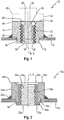
- Fig. 1
- eine Schnittdarstellung einer Sondenträgeranordnung mit einer daran getragenen Meßsonde;
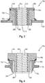
- Fig. 2
- eine Schnittdarstellung einer alternativ ausgebildeten Sondenträgeranordnung;
- Fig. 3
- eine Schnittdarstellung einer weiteren alternativ ausgebildeten Sondenträgeranordnung;
- Fig. 4
- eine Schnittdarstellung einer weiteren alternativ ausgebildeten Sondenträgeranordnung.
- In
Fig. 1 ist eine insbesondere im Bereich einer Abgasanlage einer Brennkraftmaschine in einem Fahrzeug einzusetzende Sondenträgeranordnung allgemein mit 10 bezeichnet. Die Sondenträgeranordnung 10 umfasst einen Sondentragekörper 12, der beispielsweise bereitgestellt sein kann durch ein abgasführendes Rohr einer Abgasanlage oder ein Gehäuse einer Abgasbehandlungseinheit, wie zum Beispiel Katalysator oder Partikelfilter. - An dem Sondentragekörper 12 ist ein Sondenstutzen 14 angebracht. Hierzu weist der Sondentragekörper 12 eine Öffnung 16 auf, in welche ein dem Sondentragekörper 12 nahe liegendes Ende 18 des Sondenstutzens 14 eingreift. Mit einer Radialschulter 20 kann der Sondenstutzen 14 an einer Außenoberfläche des Sondentragekörpers 12 aufliegend positioniert werden, so dass eine definierte Positionierung des Sondenstutzens 14 am Sondentragekörper 12 vorgegeben ist. Eine feste Anbindung des Sondenstutzens 14 an den Sondentragekörper kann durch Materialschluss, beispielsweise eine unterbrechungsfrei umlaufende Schweißnaht 22, bereitgestellt werden, wodurch gleichzeitig auch ein gasdichter Abschluss im Bereich des Übergangs zwischen dem Sondenstutzen 14 und dem Sondentragekörper 12 gewährleistet ist. Es ist darauf hinzuweisen, dass die Schweißverbindung zwischen dem Sondenstutzen 14 und dem Sondentragekörper 12 durch verschiedenste Schweißverfahren, wie zum Beispiel KE- Schweißen, Laserschweißen, Elektronenstrahlschweißen, Ultraschallschweißen oder Reibschweißen, erzeugt werden kann.
- Im Sondenstutzen 14 ist eine in Richtung einer Einsatzaufnahmeöffnung-Längsachse E sich erstreckende Einsatzaufnahmeöffnung 24 ausgebildet. An deren Innenumfang bzw. dem Innenumfang des Sondenstutzens 14 ist ein Innengewinde 26 ausgebildet.
- In der Einsatzaufnahmeöffnung 24 ist ein Sondentrageeinsatz 28 angeordnet. Der Sondentrageeinsatz 28 ist in dem in
Fig. 1 dargestellten Ausgestaltungsbeispiel nach Art einer Spindel ausgebildet und weist an seinem Außenumfang ein Außengewinde 30 auf. Mit diesem Außengewinde 30 ist der Sondentrageeinsatz 28 in Gewindeeingriff mit dem Innengewinde 26 des Sondenstutzens 14, so dass durch die bei diesem Gewindeeingriff erzeugte Reibwechselwirkung zwischen dem Sondenstutzen 14 und dem Sondentrageeinsatz 28 grundsätzlich eine definierte Positionierung zwischen diesen beiden Elementen gewährleistet ist. Dabei kann beispielsweise vorgesehen sein, dass der Sondentrageeinsatz 28 weder im Bereich seines dem Sondentragekörper 12 nahe liegenden axialen Endes 32, noch in seinem vom Sondentragekörper 12 entfernten axialen Ende 34 über die im Sondenstutzen 14 ausgebildete Einsatzaufnahmeöffnung 24 axial hervor steht. - Im Sondentrageeinsatz 28 ist eine Sondenaufnahmeöffnung 36 ausgebildet. Die Sondenaufnahmeöffnung 36 erstreckt sich in Richtung einer Sondenaufnahmeöffnung-Längsachse S durch den Sondentrageeinsatz 28 vollständig hindurch, wobei die Sondenaufnahmeöffnung 36 und die Einsatzaufnahmeöffnung 24 zueinander koaxial angeordnet sein können, so dass deren Längsachsen E und S einander entsprechen.
- An einem Innenumfang der Sondenaufnahmeöffnung 36 bzw. des Sondentrageeinsatzes 28 ist ein Innengewinde 38 vorgesehen. In dieses Innengewinde 38 ist ein mit Außengewinde versehener Schaftbereich einer in
Fig. 1 angedeuteten Meßsonde 40 eingeschraubt. Ein Kopfbereich 42 der Meßsonde 40 stützt sich im Einbauzustand entweder direkt oder gegebenenfalls unter Zwischenlagerung eines Dichtungselements an einer Sondenabstützfläche 44 ab, die an einem vom Sondentragekörper 12 entfernten axialen Ende 46 des Sondenstutzens 14 die Einsatzaufnahmeöffnung 24 ringartig umgebend ausgebildet ist. Das axiale Ende 46 des Sondenstutzen 14 liegt also von dem Sondentragekörper 12 weiter entfernt, als das axiale Ende 18. - Über die im Sondentrageeinsatz 28 ausgebildete Sondenaufnahmeöffnung 36 und auch die im Sondenstutzen 14 ausgebildete Einsatzaufnahmeöffnung 24, die beide zu einem von dem Sondentragekörper 12 umschlossenen und von Abgas durchströmten Volumen offen sind, kann die Meßsonde 40 in Wechselwirkung mit dem in diesem Volumen strömenden Abgas treten. Beispielsweise kann die Meßsonde 40 als Sauerstoffsensor ausgebildet sein, welcher den Sauerstoffgehalt erfasst. Alternativ kann die Meßsonde 40 als Temperatursensor oder als anderer zur Erfassung der Zusammensetzung des Abgases geeigneter Sensor ausgebildet sein. Es ist auch darauf hinzuweisen, dass an einer Abgasanlage mehrere derartige Meßsonden 40 verschiedener Art aufnehmende Sondenträgeranordnungen10 an geeigneter Positionierung vorgesehen sein können.
- Für den Sondenstutzen 14 einerseits und den Sondentrageeinsatz 28 andererseits können für deren Funktionalität jeweils besonders geeignete Aufbaumaterialien ausgewählt werden. So kann beispielsweise der Sondenstutzen 14 mit einem Aufbaumaterial aufgebaut werden, das eine auch unter thermischer Belastung sehr stabile materialschlüssige Verbindung mit dem Sondentragekörper 12 gewährleistet. Ist beispielsweise der Sondentragekörper 12 mit ferritischem Metallmaterial aufgebaut, ist es besonders vorteilhaft, auch den Sondenstutzen 14 mit ferritischem Metallmaterial auszugestalten, da dann gewährleistet ist, dass diese Materialien zueinander im Wesentlichen gleiche thermische Ausdehnungen aufweisen und daher im Angrenzungsbereich zwischen dem Sondenstutzen 14 und dem Sondentragekörper 12, insbesondere dort, wo die materialschlüssige Verbindung erzeugt ist, auch bei Erwärmung bzw. beim Abkühlen die materialschlüssige Verbindung besonders belastende Spannungen im Wesentlichen nicht auftreten.
- Der Sondentrageeinsatz 28 kann mit einem Aufbaumaterial bereitgestellt werden, das für die Verbindungswechselwirkung mit der darin zu positionierenden Meßsonde 40 besonders geeignet ist. Ist eine derartige Meßsonde 40 insbesondere dort, wo diese in dem in Eingriff mit dem Innengewinde 38 zu bringenden Bereich ein Außengewinde aufweist, mit austenitischem Metallmaterial aufgebaut, so ist es besonders vorteilhaft, auch den Sondentrageeinsatz 28 mit austenitischem Metallmaterial auszugestalten. Dadurch ist einerseits gewährleistet, dass auch diese beiden Elemente zueinander näherungsweise gleiche thermische Ausdehnungen aufweisen, wenn eine derartige Abgasanlage erwärmt bzw. abgekühlt wird. Andererseits wird dadurch die Gefahr einer Korrosion, die zu einem Festfressen der Meßsonde 40 im Sondentrageeinsatz 28 führen kann, gemindert.
- Wird für den Sondenstutzen 14 ferritisches Metallmaterial verwendet, während für den Sondentrageeinsatz 28 austenitisches Metallmaterial verwendet wird, bedeutet dies, dass aufgrund der deutlich unterschiedlichen thermischen Ausdehnungskoeffizienten dieser Materialien bei einer Erwärmung der Sondenträgeranordnung 10 der Sondentrageeinsatz 28 sich deutlich stärker ausdehnen wird, als der Sondenstutzen 14. Die dadurch auf den Sondenstutzen 14 ausgeübte Belastung kann zu einer geringfügigen plastischen Verformung des Sondenstutzens 14 führen mit der Folge, dass bei einem nachfolgenden Abkühlen ein geringfügiges Spiel in den miteinander in Eingriff stehenden Gewinden 26, 30 entstehen könnte. Auch bei Ausgestaltung des Sondenstutzens 14 aus austenitischem Metallmaterial und des Sondentrageeinsatzes 28 aus ferritischem Metallmaterial könnten wiederholt auftretende Erwärmungs- und Abkühlprozesse und dabei entstehende plastische Verformungen zu einem Lockern des Gewindeeingriffs führen. Dies ist jedoch aufgrund des Umstandes, dass der Sondentrageeinsatz 28 mit der Meßsonde 40 verschraubt und somit in Richtung der Längsachsen S und E mit dieser verspannt ist, unproblematisch, da aufgrund dieser Verspannung die miteinander in Eingriff stehenden Gewinde 26, 30 zueinander axial verspannt sind und somit eine aufgrund dieser Verspannung hervorgerufene Reibwechselwirkung eine stabile Halterung des Sondentrageeinsatzes 28 im Sondenstutzen 14 gewährleistet. Eine entsprechende axiale Verspannung entsteht auch zwischen dem am Sondentrageeinsatz 28 vorgesehenen Innengewinde 38 und dem an der Meßsonde 40 vorgesehenen Außengewinde.
- Eine alternative Ausgestaltung der Sondenträgeranordnung ist in
Fig. 2 dargestellt. Komponenten, welche vorangehend beschriebenen Komponenten hinsichtlich Aufbau bzw. Funktion entsprechen, sind mit dem gleichen Bezugszeichen unter Hinzufügung des Anhangs "a" bezeichnet. - Bei dem in
Fig. 2 dargestellten Aufbau der Sondenträgeranordnung 10a ist der Sondenstutzen 14a am Innenumfang der darin ausgebildeten Einsatzaufnahmeöffnung 24a im Wesentlichen unstrukturiert, also insbesondere ohne Innengewinde ausgebildet. Beispielsweise kann die Einsatzaufnahmeöffnung 24a im Wesentlichen zylindrisch ausgebildet sein, kann also in Richtung der Einsatzaufnahmeöffnung-Längsachse E mit dem Wesentlichen konstanter Querschnittsgeometrie und Querschnittsabmessung bereitgestellt sein. Entsprechend ist auch der Sondentrageeinsatz 28a an seinem Außenumfang im Wesentlichen unstrukturiert, insbesondere ohne Außengewinde ausgebildet. In Anpassung an die Geometrie der Einsatzaufnahmeöffnung 24a kann auch der Sondentrageeinsatz 28a am Außenumfang des im Sondenstutzen 14a aufzunehmenden Längenbereichs desselben mit im Wesentlichen zylindrischer Geometrie bereitgestellt sein. - Im Bereich seines dem Sondentragekörper 12a nahe liegenden axialen Endes 32a weist der Sondentrageeinsatz 28a einen nach radial außen vorspringenden, um die Sondenaufnahmeöffnung-Längsachse S vorzugsweise vollständig umlaufenden Einsatzflansch 48a auf. Mit diesem Einsatzflansch 48a stützt der Sondentrageeinsatz 28a sich in Richtung der Einsatzaufnahmeöffnung-Längsachse E an dem dem Sondentragekörper 12a nahe liegenden und insbesondere in die Öffnung 16a eingreifenden axialen Ende 18a des Sondenstutzens 14a axial ab.
- Der Sondentrageeinsatz 28a und die Einsatzaufnahmeöffnung 24a können so aufeinander abgestimmt sein, dass beim Zusammenbau der Sondenträgeranordnung 10a eine Presspassung erzeugt wird, wenn der Sondentrageeinsatz 28a in die Einsatzaufnahmeöffnung 24a eingeführt wird. Ein Herausfallen des Sondentrageeinsatzes 28a aus dem Sondenstutzen 14a kann somit auch in einem Zustand, in welchem eine Meßsonde noch nicht in den Sondentrageeinsatz 28a eingeschraubt ist, verhindert werden. Wird eine Meßsonde in die Sondenaufnahmeöffnung 36a eingeschraubt, so dass diese mit ihrem in
Fig. 1 erkennbaren Kopfbereich sich an der am Sondenstutzen 14a gebildeten Sondenabstützfläche 44a axial abstützt, wird eine Verspannung zwischen der Meßsonde und dem Sondentrageeinsatz 28a erzeugt, da dieser mit seinem Einsatzflansch 48a gegen das axiale Ende 18a des Sondenstutzens 14a gepresst wird. Auch somit wird eine von unterschiedlichen thermischen Ausdehnungskoeffizienten des Sondenstutzens 14a einerseits und des Sondentrageeinsatzes 28a andererseits im Wesentlichen nicht beeinflusste stabile und gasdichte Halterung für eine Meßsonde gewährleistet. - Es ist darauf hinzuweisen, dass auch bei dieser Ausgestaltungsart der Sondenstutzen 14a in der vorangehend beschriebenen Art und Weise an den Sondentragekörper 12a angebunden sein kann und für den Sondentragekörper 12a, den Sonnentragestutzen 14a, den Sondentrageeinsatz 28a und die in
Fig. 2 nicht dargestellte Meßsonde die vorangehend mit Bezug auf dieFig. 1 beschriebenen Aufbaumaterialien gleicher Art bzw. unterschiedlicher Art gewählt werden können. - Eine weitere alternative Ausgestaltung der Sondenträgeranordnung ist in
Fig. 3 dargestellt. Komponenten, welche vorangehend beschriebenen Komponenten hinsichtlich Aufbau bzw. Funktion entsprechen, sind mit dem gleichen Bezugszeichen unter Hinzufügung des Anhangs "b" bezeichnet. - Die Ausgestaltungsform der
Fig. 3 unterscheidet sich von der inFig. 2 dargestellten Ausgestaltungsform im Wesentlichen dadurch, dass der Einsatzflansch 48b an dem von dem Sondentragekörper 12b entfernten axialen Ende 46b des Sondenstutzens 14b axial abgestützt ist. Da der Einsatzflansch 48b dabei die vom Sondentragekörper 12b abgewandte Stirnfläche des Sondenstutzens 14b überdeckt, stellt der Sondentrageeinsatz 28b an seinem vom Sondentragekörper 12b entfernt liegenden axialen Ende 34b im Wesentlichen mit dem Einsatzflansch 48b die Sondenabstützfläche 44b bereit, an welcher der Kopfbereich der Meßsonde sich axial abstützen kann. - Für eine feste Verbindung zwischen dem Sondenstutzen 14b und dem Sondentrageeinsatz 28b ist bei dieser Ausgestaltungsform eine materialschlüssige Verbindung beispielsweise durch eine in Umfangsrichtung um die Längsachsen E, S vollständig umlaufende Schweißnaht 50b vorgesehen. Auf diese kann durch verschiedene, insbesondere die vorangehend angegebenen Schweißverfahren bereitgestellt werden. Werden für den Sondenstutzen 14b einerseits und den Sondentrageeinsatz 28b andererseits unterschiedliche Aufbaumaterialien, also beispielsweise ferritisches Metallmaterial und austenitisches Metallmaterial, verwendet, bedeutet dies, dass eine Schweißverbindung erzeugt wird zwischen zwei aus derartigen unterschiedlichen und insbesondere auch unterschiedliche thermische Ausdehnungskoeffizienten aufweisenden Materialien. Da diese Schweißverbindung jedoch an dem vom Sondentragekörper 12b entfernten axialen Ende 46b des Sondenstutzens 14b erzeugt wird, liegt diese Schweißverbindung in einem thermisch weniger stark belasteten Bereich, als beispielsweise die im Angrenzungsbereichen des Sondenstutzens 14b an den Sondentragekörper 12b generierte Schweißnaht 22b. Die Gefahr, dass aufgrund unterschiedlicher thermischer Ausdehnungen im Bereich der Schweißnaht 50b derart große Spannungen auftreten können, dass eine Beschädigung der Schweißnaht 50b entstehen könnte, besteht somit nicht. Von besonderem Vorteil ist weiter, dass die Meßsonde ausschließlich mit dem Sondentrageeinsatz 28b in Kontakt kommt, so dass eine aufgrund unterschiedlicher Materialien eingeführte Korrosionsgefahr eliminiert ist.
- Eine weitere alternative Ausgestaltung der Sondenträgeranordnung ist in
Fig. 4 dargestellt. Komponenten, welche vorangehend beschriebenen Komponenten hinsichtlich Aufbau bzw. Funktion entsprechen, sind mit dem gleichen Bezugszeichen unter Hinzufügung des Anhangs "c" bezeichnet. - Bei dem in
Fig. 4 dargestellten Aufbau ist der Sondentragekörper 12c mit dem Sondenstutzen 14c integral, also einstückig bzw. als ein Materialblock ausgebildet. Dies kann beispielsweise dadurch erzeugt werden, dass ein rohrartiger oder plattenartiger Rohling für den Sondentragekörper 12c einem Fließbohrvorgang unterzogen wird, bei welchem durch starke Belastung vermittels eines rotierenden Dorns dort, wo eine Öffnung, also die Einsatzaufnahmeöffnung 24c, und mit dieser auch der Sondenstutzen 14c zu bilden ist, das Aufbaumaterial des Rohlings verformt wird. Durch die Formgebung des bei diesem auch unter den Bezeichnungen Flowdrill-Verfahren, Glowdrill-Verfahren oder Thermodrill-Verfahren bekannten Umformungsvorgang eingesetzten Dorns kann auch die Form des dabei erzeugten und den Sondenstutzen 14c bereitstellenden Ausformungsbereichs bestimmt werden. - Bei dieser Ausgestaltungsart ist der Sondentrageeinsatz 28c mit seinem Einsatzflansch 48c das vom Sondentragekörper 12c entfernte axiale Ende 46c des Sondenstutzens 14c radial übergreifend positioniert und mit diesem durch die Schweißnaht 50c materialschlüssig fest und gasdicht verbunden. Die Sondenabstützfläche 44c ist an dem von dem Sondentragekörper 12c entfernten axialen Ende 34c des Sondentrageeinsatzes 28c vorgesehen.
- Jede der vorangehend beschriebenen Ausgestaltungsformen weist den wesentlichen Vorteil auf, dass für den Sondenstutzen ein für dessen Anbindung an den Sondentragekörper besonders geeignetes Material eingesetzt werden kann. Ist der Sondentragekörper beispielsweise mit ferritischem Aufbaumaterial aufgebaut, kann auch der Sondenstutzen mit ferritischem Aufbaumaterial bereitgestellt werden. Ist der Sondentragekörper mit austenitischem Aufbaumaterial aufgebaut, kann auch der Sondenstutzen mit austenitischem Aufbaumaterialien bereitgestellt werden. Entsprechendes gilt auch für die Auswahl des Aufbaumaterials des Sondentrageeinsatzes in Bezug auf das Aufbaumaterial einer darin aufzunehmenden Meßsonde. Ist die Meßsonde insbesondere in ihrem zur Anbindung an den Sondentrageeinsatz vorgesehenen Bereich mit austenitischem Material aufgebaut, es ist besonders vorteilhaft, wenn auch der Sondentrageeinsatz mit austenitischem Material aufgebaut ist. Ist die Meßsonde in ihrem zur Anbindung an den Sondentrageeinsatz vorgesehenen Bereich mit ferritischem Material aufgebaut, es ist kann auch der Sondentrageeinsatz mit ferritischem Material aufgebaut sein.
- Als ferritische Aufbaumaterialien können dabei beispielsweise Ferrit Nr. 1.4509 gemäß DIN EN 10088-02 mit der Bezeichnung X2CrTiNb18 oder Ferrit Nr. 1.4521 gemäß DIN EN 10088-02 mit der Bezeichnung X2CrMoTi18-2 eingesetzt werden. Als austenitische Aufbaumaterialien können beispielsweise Austenit Nr. 1.4301 gemäß DIN EN 10088-02 mit der Bezeichnung X5CrNi18-10 oder Austenit Nr. 1.4828 gemäß DIN EN 10088-02 mit der Bezeichnung X15CrNiSi20-12 eingesetzt werden.
- In jedem Falle wird durch die erfindungsgemäße Ausgestaltung einer Sondenträgeranordnung gewährleistet, dass durch thermischer Belastungen hervorgerufene unterschiedliche Ausdehnungen im Bereich des Sondenstutzens einerseits und der daran anschließenden Elemente, also des Sondentrageeinsatzes bzw. des Sondentragekörpers, andererseits nicht zu derartigen mechanischen Belastungen führen können, dass Verbindungen, insbesondere materialschlüssige Verbindungen, beschädigt werden. Auch die Gefahr, dass durch unterschiedliche in Kontakt miteinander stehende Materialien eine übermäßige Korrosion auftritt, besteht nicht.
- Von besonderem Vorteil ist weiter, dass mit dem mehrteiligen Aufbau die Möglichkeit besteht, durch die Kombination von beispielsweise mit verschiedenen Materialien oder/und auch verschiedenen Formgebungen aufgebauten Bauteilen leicht eine Anpassung an verschiedene Aufbauumgebungen vorzunehmen. So können beispielsweise Sondentrageeinsätze mit verschieden dimensionierten Sondenaufnahmeöffnungen vorgehalten werden, um bei unveränderter Bauart des Sondenstutzens in diesem verschieden gestaltete Messsonden aufnehmen zu können. Auch ist es möglich, in einem Sondentrageeinsatz mehrere Sondenaufnahmeöffnungen vorzusehen, um auf diese Art und Weise an einem Sondenstutzen mehrere Messsonden aufnehmen zu können. Grundsätzlich sei auch darauf hingewiesen, dass diese hinsichtlich der Variabilität einer Sondenträgeranordnung gebotenen Vorteile auch dann Anwendung finden können, wenn für die verschiedenen Bestandteile derselben, insbesondere den Sondenstutzen und den Sondentrageeinsatz, gleiche Aufbaumaterialien gewählt werden.
Claims (15)
- Sondenträgeranordnung, insbesondere für eine Abgasanlage einer Brennkraftmaschine, umfassend einen an einem Sondentragekörper (12; 12a; 12b; 12c) vorgesehenen Sondenstutzen (14; 14a; 14b; 14c) mit wenigstens einer in Richtung einer Einsatzaufnahmeöffnung-Längsachse (E) sich erstreckenden Einsatzaufnahmeöffnung (24; 24a; 24b; 24c) und einen in der Einsatzaufnahmeöffnung (24; 24a; 24b; 24c) angeordneten Sondentrageeinsatz (28; 28a; 28b; 28c) mit wenigstens einer in Richtung einer Sondenaufnahmeöffnung-Längsachse (S) sich erstreckenden Sondenaufnahmeöffnung (36; 36a; 36b; 36c).
- Sondenträgeranordnung nach Anspruch 1, dadurch gekennzeichnet,
dass der Sondenstutzen (14; 14a; 14b) von dem Sondentragekörper (12; 12a; 12b) separat ausgebildet ist und an dem Sondentragekörper (12; 12a; 12b) durch Materialschluss, vorzugsweise Verschweißen, festgelegt ist,
oder
dass der Sondenstutzen (14c) mit dem Sondentragekörper (12c) integral ausgebildet ist, vorzugsweise durch Fließbohren. - Sondenträgeranordnung einem der vorangehenden Ansprüche, dadurch gekennzeichnet, dass der Sondentrageeinsatz (28) mit dem Sondenstutzen (14) durch Gewindeeingriff verbunden ist.
- Sondenträgeranordnung nach Anspruch 3, dadurch gekennzeichnet, dass an einem Innenumfangsbereich der Einsatzaufnahmeöffnung (24) ein Innengewinde (26) vorgesehen ist, und dass an einem Außenumfangsbereich des Sondentrageeinsatzes (28) ein mit dem Innengewinde (26) des Sondenstutzens (14) in Eingriff stehendendes Außengewinde (30) vorgesehen ist.
- Sondenträgeranordnung nach Anspruch 1 oder 2, dadurch gekennzeichnet, dass ein Innenumfangsbereich der Einsatzaufnahmeöffnung (24a; 24b; 24c) oder/und ein Außenumfangsbereich des Sondentrageeinsatzes (28a; 28b; 28c) im Wesentlichen unstrukturiert, vorzugsweise im Wesentlichen zylindrisch, ausgebildet sind,
vorzugsweise wobei der Sondentrageeinsatz (28a; 28b; 28c) in der Einsatzaufnahmeöffnung (24a; 24b; 24c) des Sondenstutzens (14a; 14b; 14c) mit Presspassung aufgenommen ist. - Sondenträgeranordnung nach einem der vorangehenden Ansprüche, dadurch gekennzeichnet, dass der Sondentrageeinsatz (28b; 28c) mit dem Sondenstutzen (14b; 14c) oder/und dem Sondentragekörper durch Materialschluss, vorzugsweise Verschweißen, verbunden ist.
- Sondenträgeranordnung nach einem der vorangehenden Ansprüche, dadurch gekennzeichnet, dass der Sondentrageeinsatz (28a; 28b; 28c) einen bezüglich der Sondenaufnahmeöffnung-Längsachse (S) nach radial außen vorspringenden und in Richtung der Sondenaufnahmeöffnung-Längsachse (S) an dem Sondenstutzen (14a; 14b; 14c) oder/und dem Sondentragekörper abgestützten Einsatzflansch (48a; 48b; 48c) aufweist.
- Sondenträgeranordnung nach Anspruch 6 und Anspruch 7, dadurch gekennzeichnet, dass der Sondentrageeinsatz (28b; 28c) mit dem Sondenstutzen (14b; 14c) oder/und dem Sondentragekörper im Bereich des Einsatzflansches (48b; 48c) durch Materialschluss verbunden ist.
- Sondenträgeranordnung nach Anspruch 8, dadurch gekennzeichnet, dass an dem Sondentrageeinsatz (28b; 28c) im Bereich des Einsatzflansches (48b; 48c) eine die Sondenaufnahmeöffnung (24b; 24c) in dem Sondentrageeinsatz (28b; 28c) umgebende Sondenabstützfläche (44b; 44c) ausgebildet ist.
- Sondenträgeranordnung nach einem der Ansprüche 1-8, dadurch gekennzeichnet, dass an dem Sondenstutzen (14; 14a) an einem von dem Sondentragekörper (12; 12a) entfernten axialen Ende (46; 46a) eine die Einsatzaufnahmeöffnung (24; 24a) umgebende Sondenabstützfläche (44; 44a) ausgebildet ist,
vorzugsweise wobei der Einsatzflansch (48a) an einem dem Sondentragekörper (12a) nahe liegenden axialen Ende (18a) des Sondenstutzens (14a) abgestützt ist. - Sondenträgeranordnung einem der vorangehenden Ansprüche, dadurch gekennzeichnet, dass ein Element von Sondenstutzen (14; 14a; 14b; 14c) und Sondentrageeinsatz (28; 28a; 28b; 28c) mit austenitischem Material aufgebaut ist und das andere Element von Sondenstutzen (14; 14a; 14b; 14c) und Sondentrageeinsatz (28; 28a; 28b; 28c) mit ferritischem Material aufgebaut ist.
- Abgasanlage für eine Brennkraftmaschine, umfassend eine Sondenträgeranordnung (10; 10a; 10b; 10c) nach einem der vorangehenden Ansprüche, wobei der Sondentragekörper (12; 12a; 12b; 12c) durch ein abgasführendes Gehäuse bereitgestellt ist.
- Abgasanlage nach Anspruch 12, dadurch gekennzeichnet, dass an einem von dem Gehäuse entfernten axialen Ende des Sondenstutzens (14; 14a) oder des Sondentrageeinsatzes (28b; 28c) eine Sondenabstützfläche (44; 44a; 44b; 44c) für eine in der Sondenaufnahmeöffnung (36; 36a; 36b; 36c) aufgenommene Meßsonde (40) ausgebildet ist.
- Abgasanlage nach Anspruch 12 oder 13, sofern auf Anspruch 6 rückbezogen, dadurch gekennzeichnet, dass der Sondentrageeinsatz (28b; 28c) mit dem Sondenstutzen (14b; 14c) in einem von dem Gehäuse entfernten axialen Ende (46b; 46c) des Sondenstutzens (14b; 14c) durch Materialschluss verbunden ist.
- Abgasanlage nach Anspruch 12 oder 13, sofern auf Anspruch 7 rückbezogen, dadurch gekennzeichnet, dass der Einsatzflansch (48a) an einem dem Gehäuse nahe liegenden axialen Ende (18a) des Sondenstutzens (14a) abgestützt ist.
Applications Claiming Priority (1)
| Application Number | Priority Date | Filing Date | Title |
|---|---|---|---|
| DE102019104770.6A DE102019104770A1 (de) | 2019-02-26 | 2019-02-26 | Sondenträgeranordnung |
Publications (2)
| Publication Number | Publication Date |
|---|---|
| EP3702594A1 true EP3702594A1 (de) | 2020-09-02 |
| EP3702594B1 EP3702594B1 (de) | 2022-03-30 |
Family
ID=69571908
Family Applications (1)
| Application Number | Title | Priority Date | Filing Date |
|---|---|---|---|
| EP20156802.9A Active EP3702594B1 (de) | 2019-02-26 | 2020-02-12 | Sondenträgeranordnung |
Country Status (4)
| Country | Link |
|---|---|
| US (1) | US11467063B2 (de) |
| EP (1) | EP3702594B1 (de) |
| CN (1) | CN111608778B (de) |
| DE (1) | DE102019104770A1 (de) |
Families Citing this family (3)
| Publication number | Priority date | Publication date | Assignee | Title |
|---|---|---|---|---|
| DE102021123190A1 (de) * | 2021-09-08 | 2023-03-09 | Purem GmbH | Schweißbauteil und Verfahren zum Verschweißen eines derartigen Schweißbauteils mit einem Bauteil |
| JP7232969B1 (ja) * | 2023-01-30 | 2023-03-03 | シチズンファインデバイス株式会社 | 圧力検出装置 |
| DE102024106105A1 (de) | 2024-03-04 | 2025-09-04 | Purem GmbH | Sondentragebaugruppe, insbesondere für eine Abgasanlage einer Brennkraftmaschine |
Citations (6)
| Publication number | Priority date | Publication date | Assignee | Title |
|---|---|---|---|---|
| US4495810A (en) * | 1983-04-20 | 1985-01-29 | General Electric Company | Probe mounting system |
| DE10210313A1 (de) * | 2002-03-08 | 2003-10-02 | Bosch Gmbh Robert | Meßfühleranordnung |
| DE10324956A1 (de) * | 2003-06-03 | 2005-01-27 | Robert Bosch Gmbh | Messfühler |
| US20070178026A1 (en) * | 2006-02-01 | 2007-08-02 | Roth Gregory T | Exhaust treatment device with sensor and method of making |
| DE102010031656A1 (de) * | 2010-07-22 | 2012-01-26 | Robert Bosch Gmbh | Vorrichtung zum Einbau eines Messfühlers |
| DE102016113231A1 (de) * | 2016-07-19 | 2018-01-25 | Eberspächer Exhaust Technology GmbH & Co. KG | Stutzenbaugruppe, insbesondere für eine Abgasbehandlungsanordnung einer Abgasanlage einer Brennkraftmaschine |
Family Cites Families (12)
| Publication number | Priority date | Publication date | Assignee | Title |
|---|---|---|---|---|
| GB2027884B (en) | 1978-08-14 | 1983-04-27 | Electrical Thermometer Co Ltd | Thermometer mounting |
| JPH05332117A (ja) * | 1992-05-29 | 1993-12-14 | Hino Motors Ltd | オイルパン構造 |
| US5836155A (en) * | 1994-05-06 | 1998-11-17 | Sanshin Kogyo Kabushiki Kaisha | Sensor arrangement for engine control system |
| US7452512B2 (en) | 2005-02-01 | 2008-11-18 | Et Us Holdings Llc | Converter assembly with insulated sensor boss |
| DE102006044736B4 (de) * | 2006-09-20 | 2008-07-24 | Roth-Technik Austria Ges.M.B.H. | Abgasführendes Gehäuse oder Rohr einer Abgasanlage einer Brennkraftmaschine |
| CN201697719U (zh) | 2010-04-27 | 2011-01-05 | 新疆三叶管道技术有限责任公司 | 免停产测温套管 |
| JP2013112054A (ja) * | 2011-11-25 | 2013-06-10 | Bosch Corp | ブレーキ液圧制御装置 |
| DE102013111589B4 (de) * | 2013-08-14 | 2016-09-22 | Borgwarner Ludwigsburg Gmbh | Kraftstoffverdampfer |
| JP2016138514A (ja) | 2015-01-28 | 2016-08-04 | 日本特殊陶業株式会社 | アダプター、金具セットおよびスパークプラグ |
| CN204532553U (zh) * | 2015-04-02 | 2015-08-05 | 中国航空工业集团公司沈阳发动机设计研究所 | 一种浮动支承固定结构 |
| US10753516B2 (en) | 2016-11-23 | 2020-08-25 | Ford Global Technologies, Llc | Flared exhaust gas pressure tube having keyed washer |
| CN206571554U (zh) | 2017-03-29 | 2017-10-20 | 宁波三峰机械电子股份有限公司 | 氧传感器安装座 |
-
2019
- 2019-02-26 DE DE102019104770.6A patent/DE102019104770A1/de not_active Withdrawn
-
2020
- 2020-02-12 EP EP20156802.9A patent/EP3702594B1/de active Active
- 2020-02-24 US US16/799,472 patent/US11467063B2/en active Active
- 2020-02-26 CN CN202010118212.5A patent/CN111608778B/zh active Active
Patent Citations (6)
| Publication number | Priority date | Publication date | Assignee | Title |
|---|---|---|---|---|
| US4495810A (en) * | 1983-04-20 | 1985-01-29 | General Electric Company | Probe mounting system |
| DE10210313A1 (de) * | 2002-03-08 | 2003-10-02 | Bosch Gmbh Robert | Meßfühleranordnung |
| DE10324956A1 (de) * | 2003-06-03 | 2005-01-27 | Robert Bosch Gmbh | Messfühler |
| US20070178026A1 (en) * | 2006-02-01 | 2007-08-02 | Roth Gregory T | Exhaust treatment device with sensor and method of making |
| DE102010031656A1 (de) * | 2010-07-22 | 2012-01-26 | Robert Bosch Gmbh | Vorrichtung zum Einbau eines Messfühlers |
| DE102016113231A1 (de) * | 2016-07-19 | 2018-01-25 | Eberspächer Exhaust Technology GmbH & Co. KG | Stutzenbaugruppe, insbesondere für eine Abgasbehandlungsanordnung einer Abgasanlage einer Brennkraftmaschine |
Also Published As
| Publication number | Publication date |
|---|---|
| US20200271546A1 (en) | 2020-08-27 |
| DE102019104770A1 (de) | 2020-08-27 |
| CN111608778B (zh) | 2023-02-28 |
| US11467063B2 (en) | 2022-10-11 |
| EP3702594B1 (de) | 2022-03-30 |
| CN111608778A (zh) | 2020-09-01 |
Similar Documents
| Publication | Publication Date | Title |
|---|---|---|
| DE19936008B4 (de) | Verfahren zum Anbringen eines Metallkörpers auf ein Meßrohr eines Coriolis-Massendurchflußmeßgeräts | |
| EP2184525B1 (de) | Rohrverbindung mit einem Rohr und Verfahren zur Herstellung eines Verbindungsabschnitts einer Rohrverbindung | |
| EP3702594B1 (de) | Sondenträgeranordnung | |
| DE3801473A1 (de) | Verbindungsvorrichtung | |
| EP1741945A1 (de) | Gebaute Nockenwelle | |
| EP2574807B1 (de) | Verbindung zwischen einer Welle und einem Nabenbauteil sowie Verfahren zum Herstellen der Verbindung | |
| EP0327080B1 (de) | Rohrklemmverbindung | |
| WO2008028651A1 (de) | Verfahren zum montieren einer schraube und eines gewindepanzernden elementes sowie anordnung zum durchführen des verfahrens | |
| DE10244759B4 (de) | Spannfutter zum thermischen Einschrumpfen von Schäften | |
| DE102009029781A1 (de) | Bremsscheibe und Verfahren zu deren Herstellung | |
| WO2005049980A1 (de) | Leichtbauventil | |
| DE102011109130A1 (de) | Flansch, Verbindungsanordnung und Verfahren zur axialen Anbindung eines Zug- und/oder Druckstabes | |
| EP0222855B1 (de) | Verfahren zur herstellung eines schlauchnippels für hydraulisch belastete press- oder schraubarmaturen | |
| DE102008049925A1 (de) | Verbindungsverfahren für rohrförmige Bauteile | |
| DE4029008C1 (de) | ||
| DE10256334B4 (de) | Kugelgelenkvorrichtung für Gestängeverbindungen | |
| DE102012025078A1 (de) | Messfühler, insbesondere Gassensor zur Bestimmung einer physikalischen Eigenschaft eines Messgases | |
| DE102020202217A1 (de) | Sphärisches Kugelgelenk | |
| EP1225313B1 (de) | Abgasbehandlungseinrichtung | |
| DE102005026505A1 (de) | Verfahren zum Verbinden von zwei Bauelementen mittels Reibschweißen sowie Schweißverbindung | |
| EP3561358B1 (de) | Verstärkungshülse, schneidringverschraubung und verfahren | |
| DE102014220673A1 (de) | Achsgehäuse mit reibverschweißtem Bolzen | |
| DE19858295C1 (de) | Starre Rohrverbindung für Abgasrohre von Brennkraftmaschinen | |
| DE102007006804A1 (de) | Abgasreinigungsvorrichtung, insbesondere für die Abgasanlage einer Verbrennungskraftmaschine | |
| DE102008046946A1 (de) | Axiallager |
Legal Events
| Date | Code | Title | Description |
|---|---|---|---|
| PUAI | Public reference made under article 153(3) epc to a published international application that has entered the european phase |
Free format text: ORIGINAL CODE: 0009012 |
|
| STAA | Information on the status of an ep patent application or granted ep patent |
Free format text: STATUS: THE APPLICATION HAS BEEN PUBLISHED |
|
| AK | Designated contracting states |
Kind code of ref document: A1 Designated state(s): AL AT BE BG CH CY CZ DE DK EE ES FI FR GB GR HR HU IE IS IT LI LT LU LV MC MK MT NL NO PL PT RO RS SE SI SK SM TR |
|
| AX | Request for extension of the european patent |
Extension state: BA ME |
|
| STAA | Information on the status of an ep patent application or granted ep patent |
Free format text: STATUS: REQUEST FOR EXAMINATION WAS MADE |
|
| 17P | Request for examination filed |
Effective date: 20210201 |
|
| RBV | Designated contracting states (corrected) |
Designated state(s): AL AT BE BG CH CY CZ DE DK EE ES FI FR GB GR HR HU IE IS IT LI LT LU LV MC MK MT NL NO PL PT RO RS SE SI SK SM TR |
|
| STAA | Information on the status of an ep patent application or granted ep patent |
Free format text: STATUS: EXAMINATION IS IN PROGRESS |
|
| 17Q | First examination report despatched |
Effective date: 20210319 |
|
| RAP3 | Party data changed (applicant data changed or rights of an application transferred) |
Owner name: PUREM GMBH |
|
| GRAP | Despatch of communication of intention to grant a patent |
Free format text: ORIGINAL CODE: EPIDOSNIGR1 |
|
| STAA | Information on the status of an ep patent application or granted ep patent |
Free format text: STATUS: GRANT OF PATENT IS INTENDED |
|
| INTG | Intention to grant announced |
Effective date: 20211111 |
|
| GRAS | Grant fee paid |
Free format text: ORIGINAL CODE: EPIDOSNIGR3 |
|
| GRAA | (expected) grant |
Free format text: ORIGINAL CODE: 0009210 |
|
| STAA | Information on the status of an ep patent application or granted ep patent |
Free format text: STATUS: THE PATENT HAS BEEN GRANTED |
|
| AK | Designated contracting states |
Kind code of ref document: B1 Designated state(s): AL AT BE BG CH CY CZ DE DK EE ES FI FR GB GR HR HU IE IS IT LI LT LU LV MC MK MT NL NO PL PT RO RS SE SI SK SM TR |
|
| REG | Reference to a national code |
Ref country code: GB Ref legal event code: FG4D Free format text: NOT ENGLISH |
|
| REG | Reference to a national code |
Ref country code: CH Ref legal event code: EP |
|
| REG | Reference to a national code |
Ref country code: AT Ref legal event code: REF Ref document number: 1479389 Country of ref document: AT Kind code of ref document: T Effective date: 20220415 |
|
| REG | Reference to a national code |
Ref country code: DE Ref legal event code: R096 Ref document number: 502020000850 Country of ref document: DE |
|
| REG | Reference to a national code |
Ref country code: IE Ref legal event code: FG4D Free format text: LANGUAGE OF EP DOCUMENT: GERMAN |
|
| REG | Reference to a national code |
Ref country code: SE Ref legal event code: TRGR |
|
| REG | Reference to a national code |
Ref country code: LT Ref legal event code: MG9D |
|
| PG25 | Lapsed in a contracting state [announced via postgrant information from national office to epo] |
Ref country code: RS Free format text: LAPSE BECAUSE OF FAILURE TO SUBMIT A TRANSLATION OF THE DESCRIPTION OR TO PAY THE FEE WITHIN THE PRESCRIBED TIME-LIMIT Effective date: 20220330 Ref country code: NO Free format text: LAPSE BECAUSE OF FAILURE TO SUBMIT A TRANSLATION OF THE DESCRIPTION OR TO PAY THE FEE WITHIN THE PRESCRIBED TIME-LIMIT Effective date: 20220630 Ref country code: LT Free format text: LAPSE BECAUSE OF FAILURE TO SUBMIT A TRANSLATION OF THE DESCRIPTION OR TO PAY THE FEE WITHIN THE PRESCRIBED TIME-LIMIT Effective date: 20220330 Ref country code: HR Free format text: LAPSE BECAUSE OF FAILURE TO SUBMIT A TRANSLATION OF THE DESCRIPTION OR TO PAY THE FEE WITHIN THE PRESCRIBED TIME-LIMIT Effective date: 20220330 Ref country code: BG Free format text: LAPSE BECAUSE OF FAILURE TO SUBMIT A TRANSLATION OF THE DESCRIPTION OR TO PAY THE FEE WITHIN THE PRESCRIBED TIME-LIMIT Effective date: 20220630 |
|
| REG | Reference to a national code |
Ref country code: NL Ref legal event code: MP Effective date: 20220330 |
|
| PG25 | Lapsed in a contracting state [announced via postgrant information from national office to epo] |
Ref country code: LV Free format text: LAPSE BECAUSE OF FAILURE TO SUBMIT A TRANSLATION OF THE DESCRIPTION OR TO PAY THE FEE WITHIN THE PRESCRIBED TIME-LIMIT Effective date: 20220330 Ref country code: GR Free format text: LAPSE BECAUSE OF FAILURE TO SUBMIT A TRANSLATION OF THE DESCRIPTION OR TO PAY THE FEE WITHIN THE PRESCRIBED TIME-LIMIT Effective date: 20220701 Ref country code: FI Free format text: LAPSE BECAUSE OF FAILURE TO SUBMIT A TRANSLATION OF THE DESCRIPTION OR TO PAY THE FEE WITHIN THE PRESCRIBED TIME-LIMIT Effective date: 20220330 |
|
| PG25 | Lapsed in a contracting state [announced via postgrant information from national office to epo] |
Ref country code: NL Free format text: LAPSE BECAUSE OF FAILURE TO SUBMIT A TRANSLATION OF THE DESCRIPTION OR TO PAY THE FEE WITHIN THE PRESCRIBED TIME-LIMIT Effective date: 20220330 |
|
| PG25 | Lapsed in a contracting state [announced via postgrant information from national office to epo] |
Ref country code: SM Free format text: LAPSE BECAUSE OF FAILURE TO SUBMIT A TRANSLATION OF THE DESCRIPTION OR TO PAY THE FEE WITHIN THE PRESCRIBED TIME-LIMIT Effective date: 20220330 Ref country code: SK Free format text: LAPSE BECAUSE OF FAILURE TO SUBMIT A TRANSLATION OF THE DESCRIPTION OR TO PAY THE FEE WITHIN THE PRESCRIBED TIME-LIMIT Effective date: 20220330 Ref country code: RO Free format text: LAPSE BECAUSE OF FAILURE TO SUBMIT A TRANSLATION OF THE DESCRIPTION OR TO PAY THE FEE WITHIN THE PRESCRIBED TIME-LIMIT Effective date: 20220330 Ref country code: PT Free format text: LAPSE BECAUSE OF FAILURE TO SUBMIT A TRANSLATION OF THE DESCRIPTION OR TO PAY THE FEE WITHIN THE PRESCRIBED TIME-LIMIT Effective date: 20220801 Ref country code: ES Free format text: LAPSE BECAUSE OF FAILURE TO SUBMIT A TRANSLATION OF THE DESCRIPTION OR TO PAY THE FEE WITHIN THE PRESCRIBED TIME-LIMIT Effective date: 20220330 Ref country code: EE Free format text: LAPSE BECAUSE OF FAILURE TO SUBMIT A TRANSLATION OF THE DESCRIPTION OR TO PAY THE FEE WITHIN THE PRESCRIBED TIME-LIMIT Effective date: 20220330 Ref country code: CZ Free format text: LAPSE BECAUSE OF FAILURE TO SUBMIT A TRANSLATION OF THE DESCRIPTION OR TO PAY THE FEE WITHIN THE PRESCRIBED TIME-LIMIT Effective date: 20220330 |
|
| PG25 | Lapsed in a contracting state [announced via postgrant information from national office to epo] |
Ref country code: PL Free format text: LAPSE BECAUSE OF FAILURE TO SUBMIT A TRANSLATION OF THE DESCRIPTION OR TO PAY THE FEE WITHIN THE PRESCRIBED TIME-LIMIT Effective date: 20220330 Ref country code: IS Free format text: LAPSE BECAUSE OF FAILURE TO SUBMIT A TRANSLATION OF THE DESCRIPTION OR TO PAY THE FEE WITHIN THE PRESCRIBED TIME-LIMIT Effective date: 20220730 Ref country code: AL Free format text: LAPSE BECAUSE OF FAILURE TO SUBMIT A TRANSLATION OF THE DESCRIPTION OR TO PAY THE FEE WITHIN THE PRESCRIBED TIME-LIMIT Effective date: 20220330 |
|
| REG | Reference to a national code |
Ref country code: DE Ref legal event code: R097 Ref document number: 502020000850 Country of ref document: DE |
|
| PG25 | Lapsed in a contracting state [announced via postgrant information from national office to epo] |
Ref country code: DK Free format text: LAPSE BECAUSE OF FAILURE TO SUBMIT A TRANSLATION OF THE DESCRIPTION OR TO PAY THE FEE WITHIN THE PRESCRIBED TIME-LIMIT Effective date: 20220330 |
|
| PLBE | No opposition filed within time limit |
Free format text: ORIGINAL CODE: 0009261 |
|
| STAA | Information on the status of an ep patent application or granted ep patent |
Free format text: STATUS: NO OPPOSITION FILED WITHIN TIME LIMIT |
|
| 26N | No opposition filed |
Effective date: 20230103 |
|
| PG25 | Lapsed in a contracting state [announced via postgrant information from national office to epo] |
Ref country code: SI Free format text: LAPSE BECAUSE OF FAILURE TO SUBMIT A TRANSLATION OF THE DESCRIPTION OR TO PAY THE FEE WITHIN THE PRESCRIBED TIME-LIMIT Effective date: 20220330 |
|
| PG25 | Lapsed in a contracting state [announced via postgrant information from national office to epo] |
Ref country code: IT Free format text: LAPSE BECAUSE OF FAILURE TO SUBMIT A TRANSLATION OF THE DESCRIPTION OR TO PAY THE FEE WITHIN THE PRESCRIBED TIME-LIMIT Effective date: 20220330 |
|
| PG25 | Lapsed in a contracting state [announced via postgrant information from national office to epo] |
Ref country code: MC Free format text: LAPSE BECAUSE OF FAILURE TO SUBMIT A TRANSLATION OF THE DESCRIPTION OR TO PAY THE FEE WITHIN THE PRESCRIBED TIME-LIMIT Effective date: 20220330 |
|
| REG | Reference to a national code |
Ref country code: CH Ref legal event code: PL |
|
| REG | Reference to a national code |
Ref country code: SE Ref legal event code: EUG |
|
| REG | Reference to a national code |
Ref country code: BE Ref legal event code: MM Effective date: 20230228 |
|
| PG25 | Lapsed in a contracting state [announced via postgrant information from national office to epo] |
Ref country code: SE Free format text: LAPSE BECAUSE OF NON-PAYMENT OF DUE FEES Effective date: 20230213 Ref country code: LU Free format text: LAPSE BECAUSE OF NON-PAYMENT OF DUE FEES Effective date: 20230212 Ref country code: LI Free format text: LAPSE BECAUSE OF NON-PAYMENT OF DUE FEES Effective date: 20230228 Ref country code: CH Free format text: LAPSE BECAUSE OF NON-PAYMENT OF DUE FEES Effective date: 20230228 |
|
| REG | Reference to a national code |
Ref country code: IE Ref legal event code: MM4A |
|
| PG25 | Lapsed in a contracting state [announced via postgrant information from national office to epo] |
Ref country code: IE Free format text: LAPSE BECAUSE OF NON-PAYMENT OF DUE FEES Effective date: 20230212 |
|
| PG25 | Lapsed in a contracting state [announced via postgrant information from national office to epo] |
Ref country code: BE Free format text: LAPSE BECAUSE OF NON-PAYMENT OF DUE FEES Effective date: 20230228 |
|
| PGFP | Annual fee paid to national office [announced via postgrant information from national office to epo] |
Ref country code: AT Payment date: 20250417 Year of fee payment: 5 |
|
| PG25 | Lapsed in a contracting state [announced via postgrant information from national office to epo] |
Ref country code: CY Free format text: LAPSE BECAUSE OF FAILURE TO SUBMIT A TRANSLATION OF THE DESCRIPTION OR TO PAY THE FEE WITHIN THE PRESCRIBED TIME-LIMIT; INVALID AB INITIO Effective date: 20200212 |
|
| PG25 | Lapsed in a contracting state [announced via postgrant information from national office to epo] |
Ref country code: HU Free format text: LAPSE BECAUSE OF FAILURE TO SUBMIT A TRANSLATION OF THE DESCRIPTION OR TO PAY THE FEE WITHIN THE PRESCRIBED TIME-LIMIT; INVALID AB INITIO Effective date: 20200212 |
|
| PG25 | Lapsed in a contracting state [announced via postgrant information from national office to epo] |
Ref country code: TR Free format text: LAPSE BECAUSE OF FAILURE TO SUBMIT A TRANSLATION OF THE DESCRIPTION OR TO PAY THE FEE WITHIN THE PRESCRIBED TIME-LIMIT Effective date: 20220330 |
|
| PGFP | Annual fee paid to national office [announced via postgrant information from national office to epo] |
Ref country code: GB Payment date: 20260219 Year of fee payment: 7 |
|
| PGFP | Annual fee paid to national office [announced via postgrant information from national office to epo] |
Ref country code: DE Payment date: 20260217 Year of fee payment: 7 |
|
| PG25 | Lapsed in a contracting state [announced via postgrant information from national office to epo] |
Ref country code: AT Free format text: LAPSE BECAUSE OF NON-PAYMENT OF DUE FEES Effective date: 20250212 |
|
| REG | Reference to a national code |
Ref country code: AT Ref legal event code: MM01 Ref document number: 1479389 Country of ref document: AT Kind code of ref document: T Effective date: 20250212 |
|
| PGFP | Annual fee paid to national office [announced via postgrant information from national office to epo] |
Ref country code: FR Payment date: 20260223 Year of fee payment: 7 |