EP3702231A1 - Kabelspurstruktur - Google Patents
Kabelspurstruktur Download PDFInfo
- Publication number
- EP3702231A1 EP3702231A1 EP18873794.4A EP18873794A EP3702231A1 EP 3702231 A1 EP3702231 A1 EP 3702231A1 EP 18873794 A EP18873794 A EP 18873794A EP 3702231 A1 EP3702231 A1 EP 3702231A1
- Authority
- EP
- European Patent Office
- Prior art keywords
- track structure
- frame
- rail
- length
- track
- Prior art date
- Legal status (The legal status is an assumption and is not a legal conclusion. Google has not performed a legal analysis and makes no representation as to the accuracy of the status listed.)
- Granted
Links
- 230000006641 stabilisation Effects 0.000 claims abstract description 18
- 238000011105 stabilization Methods 0.000 claims abstract description 18
- 239000000463 material Substances 0.000 claims description 14
- 230000005540 biological transmission Effects 0.000 claims description 10
- 238000004891 communication Methods 0.000 claims description 8
- 230000007613 environmental effect Effects 0.000 claims description 4
- 239000007789 gas Substances 0.000 claims description 4
- 239000003989 dielectric material Substances 0.000 claims description 3
- 239000007788 liquid Substances 0.000 claims description 3
- 230000008054 signal transmission Effects 0.000 claims description 2
- 230000007704 transition Effects 0.000 abstract description 12
- 238000005096 rolling process Methods 0.000 description 8
- 238000013461 design Methods 0.000 description 7
- 230000033001 locomotion Effects 0.000 description 7
- 238000009434 installation Methods 0.000 description 6
- 230000015572 biosynthetic process Effects 0.000 description 5
- 238000010276 construction Methods 0.000 description 5
- 230000010355 oscillation Effects 0.000 description 4
- 239000000725 suspension Substances 0.000 description 4
- 229910000831 Steel Inorganic materials 0.000 description 3
- 239000002131 composite material Substances 0.000 description 3
- 238000000034 method Methods 0.000 description 3
- 230000002265 prevention Effects 0.000 description 3
- 239000010959 steel Substances 0.000 description 3
- 238000004873 anchoring Methods 0.000 description 2
- 230000008859 change Effects 0.000 description 2
- 238000011161 development Methods 0.000 description 2
- 239000011150 reinforced concrete Substances 0.000 description 2
- 230000004044 response Effects 0.000 description 2
- 239000003381 stabilizer Substances 0.000 description 2
- XLYOFNOQVPJJNP-UHFFFAOYSA-N water Substances O XLYOFNOQVPJJNP-UHFFFAOYSA-N 0.000 description 2
- OCJYIGYOJCODJL-UHFFFAOYSA-N Meclizine Chemical compound CC1=CC=CC(CN2CCN(CC2)C(C=2C=CC=CC=2)C=2C=CC(Cl)=CC=2)=C1 OCJYIGYOJCODJL-UHFFFAOYSA-N 0.000 description 1
- 241000940835 Pales Species 0.000 description 1
- 206010033546 Pallor Diseases 0.000 description 1
- 238000004026 adhesive bonding Methods 0.000 description 1
- 239000005442 atmospheric precipitation Substances 0.000 description 1
- 230000008901 benefit Effects 0.000 description 1
- 239000011230 binding agent Substances 0.000 description 1
- 238000004364 calculation method Methods 0.000 description 1
- 239000004568 cement Substances 0.000 description 1
- 239000004567 concrete Substances 0.000 description 1
- 235000011850 desserts Nutrition 0.000 description 1
- 230000000694 effects Effects 0.000 description 1
- 238000005516 engineering process Methods 0.000 description 1
- 238000003912 environmental pollution Methods 0.000 description 1
- 230000010006 flight Effects 0.000 description 1
- 238000005304 joining Methods 0.000 description 1
- 238000004519 manufacturing process Methods 0.000 description 1
- 230000013011 mating Effects 0.000 description 1
- 238000012986 modification Methods 0.000 description 1
- 230000004048 modification Effects 0.000 description 1
- 238000005457 optimization Methods 0.000 description 1
- 230000008569 process Effects 0.000 description 1
- 230000002787 reinforcement Effects 0.000 description 1
- 230000000284 resting effect Effects 0.000 description 1
- 238000007665 sagging Methods 0.000 description 1
- 230000000087 stabilizing effect Effects 0.000 description 1
- 230000000699 topical effect Effects 0.000 description 1
- 238000003466 welding Methods 0.000 description 1
Images




Classifications
-
- B—PERFORMING OPERATIONS; TRANSPORTING
- B61—RAILWAYS
- B61B—RAILWAY SYSTEMS; EQUIPMENT THEREFOR NOT OTHERWISE PROVIDED FOR
- B61B3/00—Elevated railway systems with suspended vehicles
- B61B3/02—Elevated railway systems with suspended vehicles with self-propelled vehicles
-
- B—PERFORMING OPERATIONS; TRANSPORTING
- B61—RAILWAYS
- B61B—RAILWAY SYSTEMS; EQUIPMENT THEREFOR NOT OTHERWISE PROVIDED FOR
- B61B1/00—General arrangement of stations, platforms, or sidings; Railway networks; Rail vehicle marshalling systems
-
- B—PERFORMING OPERATIONS; TRANSPORTING
- B61—RAILWAYS
- B61B—RAILWAY SYSTEMS; EQUIPMENT THEREFOR NOT OTHERWISE PROVIDED FOR
- B61B15/00—Combinations of railway systems
-
- B—PERFORMING OPERATIONS; TRANSPORTING
- B61—RAILWAYS
- B61B—RAILWAY SYSTEMS; EQUIPMENT THEREFOR NOT OTHERWISE PROVIDED FOR
- B61B5/00—Elevated railway systems without suspended vehicles
-
- Y—GENERAL TAGGING OF NEW TECHNOLOGICAL DEVELOPMENTS; GENERAL TAGGING OF CROSS-SECTIONAL TECHNOLOGIES SPANNING OVER SEVERAL SECTIONS OF THE IPC; TECHNICAL SUBJECTS COVERED BY FORMER USPC CROSS-REFERENCE ART COLLECTIONS [XRACs] AND DIGESTS
- Y02—TECHNOLOGIES OR APPLICATIONS FOR MITIGATION OR ADAPTATION AGAINST CLIMATE CHANGE
- Y02T—CLIMATE CHANGE MITIGATION TECHNOLOGIES RELATED TO TRANSPORTATION
- Y02T30/00—Transportation of goods or passengers via railways, e.g. energy recovery or reducing air resistance
Definitions
- the invention relates to the area of transport, in particular, to the elevated transport systems of string type, with rail track structure, similar to tracks of suspended and overpass types.
- This invention can be efficiently utilized in rail transport systems for passenger and cargo traffic in conditions of rough cross-country terrain, such as on land (mountains, desserts), as well as on sea legs of transportation lines (including sea crossings, straits, rivers and water bodies), as well as during elaboration of intra-urban transport highways and in the construction of inter-workshop transport structures of widely distributed production enterprises or their associations.
- Overpass transport system [1] which comprises vertical support pillars and horizontal track beam mounted on their upper ends.
- Running rails made in form of rectangular-section boxes with longitudinal slots in side walls facing each other and flat guiding rail located between running rails are laid along beam.
- Vehicle has traction drive, as well as support wheels and guiding wheels mounted on suspension, former of which have axles passing through slots in boxes. Wheels extending beyond dimensions of vehicle are located inside boxes and are in contact with bottom walls thereof, and wheels of the latter are in contact with guiding rail on both sides.
- the known transport system is characterized by high quality of protection against atmospheric precipitation and improved stabilization parameters.
- the disadvantage of such system is due to the considerable cost of laying tracks and noise of the boxes during rolling of wheels.
- the presence of joints in rail track and temperature deformation of rails of said transport system do not allow to develop velvet- smooth track for vehicle, which means that it is impossible to achieve high speed and high reliability of transportation.
- efficiency of vehicle movement stabilization by guiding wheels applied on one guiding rail appears to be insignificant, which also limits the area of practical use of similar systems.
- a suspended transport system [2] which comprises running track and vehicle in the form of body (housing).
- Running track is made in the form of two-rail track located on longitudinal beams installed on inner consoles of intermediate supports.
- the system is equipped with propulsor in the form of running carriage with electric motor and pneumatic stabilizer installed thereon.
- the body is installed under running carriage and connected thereto by means of pneumatic stabilizer.
- the disadvantages of the above transport system are the increased material structural consumption due to severely penalized bearing of track beams, as well as difficulty of transportation to site of installation of beams of long span structures, labor-intensive installation thereof in field conditions of difficult terrain and limited possibilities of their use to cover large spans between adjacent intermediate supports.
- a railway line [3] including a two-rail track 500 mm wide or more is known.
- the two-rail track is elevated above the ground on cables with use of suspensions.
- the cables themselves are suspended along the railway line above the ground surface by means of vertical supports.
- Cars or other sections of rolling stock of block trains are located on the upper surface of the two-rail track.
- a disadvantage of such solution is that the rails in said transport system have low specific bearing capacity (if understood as the ratio of payload weight to their dead weight, which is particularly important for overpass and suspension type roads), which, in this case, leads to significant increase of cost of such transport system.
- guide track [4] comprising two support elements and longitudinal element connected by cross elements, provided with side sheets connecting support elements to longitudinal element which is also sheet-shaped, wherein one part of cross elements may be connected to the support elements and the other part - to support and longitudinal elements.
- a transport system [5] consisting of support monorail and a transport module is known, wherein support monorail is embodied either as uniformly - directly resting via modules - tetrahedra on pales in the ground with starting slides and finishing anti-slopes, and its transport module as a platform with two cabins on four central two-edge wheels and four side support rollers, with auto-centering flywheels - gyroscopes, with possibility of body installation - cabin, tanks, containers, on-board platform, platform with racks for transportation of various cargoes.
- such transport system which consists of suspended monorail and transport module, in which the suspended monorail is I-beam suspended by stretches along the edges of the tetrahedron modules to two longitudinal bearing cables tightened by transverse ties and also has starting slides and finishing anti-slopes.
- the transport module is suspended.
- a disadvantage of such solution is that said transport system has a low specific bearing capacity.
- the main advantage of the abovementioned known track structures is that transport systems built on their basis practically do not occupy the land area, because track structures located above the urban development or natural landscape do not require earthen deposits, etc., for their support.
- supports When laying the route through deep gaps, gorges, rivers with deep channel, supports can be made with the help of rope suspension. As a result, it is possible to construct transport in areas with difficult landscape, and the costs of installation and operation of the transport system are reduced.
- the track supports can also be used to place outside lighting lights, to lay power cables, outside lighting cables, telephone cables, or other communications, as well as to land/disembark passengers or evacuate them from rolling stock in emergency situations.
- the transport system by Yunitski [6] which includes at least one track structure in the form of load-bearing member tensioned above the base (foundation), at span between supports, encased in body with rolling (running) surface for movement of wheel moving means positioned on the said track structure.
- the above installation optimizes cross-sectional areas of load-bearing member and rail body with rolling (running) surface, as well as tension forces of track structure and load-bearing member of this structure, justifies calculation of sagging height of track structure between adjacent supports and height of supports.
- the known transport system has insufficient rigidity, including torsional.
- Yunitski for a self-propelled track vehicle [7], which comprises at least one, tensioned above the foundation in span between anchor supports, length of rail in the form of load-bearing member enclosed in body with rolling surface for vehicle, as well as transition portions of the track on anchor supports, connected in span therebetween, with suspended portions of length of rail equipped with means of stabilization in space.
- Such transport system provides high operational and technical characteristics of the track structure.
- Yunitski which comprises at least one prestressed length of rail of width L, m, disposed above a base in a span between supports, said length of rail being provided with a means for the spatial stabilization thereof.
- the length of rail is in the form of a load-bearing member enclosed in a housing
- the stabilization means is in the form of balancing frames, fastened on track structure in spans between supports, with center of mass of each frame positioned below length of rail at distance H 1 , m, of its axis, which is related to the height of frame H 2 , m, by the ratio: 0,2 ⁇ H 1 / H 2 ⁇ 1
- weight P 0 , N, of each frame is related to distance H 1 , m, from axis of length of rail to center of mass of frame with break torque M, Nm, due to environmental load on track structure, by the ratio: 1,1 ⁇ P 0 H 1 / M ⁇ 10 , wherein, frames are spaced apart from each other and/or from supports at distance R, m, defined by the ratio: 20 ⁇ R / L ⁇ 5000 .
- the technical aim is also achieved by the fact that frames are fixed on track structure by means of support pillars.
- support pillar has height H 0 , m, determined by the ratio: 0,01 ⁇ H 0 / H 1 ⁇ 0,5 .
- load of frame is made in the form of solar battery panel.
- dielectrics are used as material of frame and/or the support pillar.
- load of frame is made in the form of cables, pipes, rods, wires fixed along the length of rail.
- Another object of the present invention is also using, as load of frame, longitudinally fixed in relation to length of rail, electric power transmission line elements and/or information signal transmission line elements and/or pipeline elements.
- the claimed string track structure (see Figs. 1 and 2 ) comprises at least one prestressed length of rail 3 of length L, m, disposed above a base 1 in span A between supports 2, said length being provided with a means 4 for spatial stabilization thereof.
- Stabilization means 4 is in the form of balancing frame 4.1.
- Length of rail 3 is in the form of load-bearing member 5 enclosed in housing 6 which has rolling (running) surface 7 that can be configured on upper surface B, side surface C and lower surface D of housing (see Fig.3 ).
- String track structure also includes track transition portions F in the form of heads 8 on supports 2, said transition portions being connected to suspended portions P of track disposed in span A between supports (see Figs. 1 and 2 ).
- supports 2 can be reinforced concrete, pipe concrete, steel column and frame structures, buildings and structures specially equipped with landing and loading platforms, located between loading and unloading stations - passenger for passenger routes and cargo for freight routes.
- Heads 8 are intended for arrangement of transition portions F of track and/or systems of communication components located on track structure 9 - power supply and/or communication networks and/or pipelines, as well as for fastening (anchoring) of tensioned elements of load-bearing member 5 of track structure.
- Fastening components of load-bearing member 5 in heads 8 of supports 2 represent any known means similar to those used in suspended and rope bridges, cable roads and prestressed reinforced concrete structures for fastening (anchoring) of tensioned load-bearing elements (reinforcement, cable ropes, high-strength wires, etc.).
- the structure of support 2 may vary depending on the mounting position thereof.
- the shape of heads 8 with fastening components of load-bearing member 5 and communication networks on anchor supports, installed on turns of track, on linear portions of track, on mountains, or end-of-route sections may be different since said components defining direction for the transition portion of the track must be smoothly coupled with the suspended portions P of track in span A between supports 2 (see Figs.1 and 2 ).
- the shape of heads 8 of supports 2 can be determined by the fact that they serve as location of loading and unloading passenger and/or cargo stations, crossroads junctions (turn-out switches and turns) of track structure 9, or branch units of the communication system. In the central part of passenger and/or cargo stations, on the transition portions F of track there is level portion (not shown on figures).
- supports 2 can be combined with buildings and construction structures (residential, industrial, office, commercial and other buildings and structures).
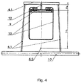
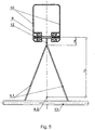
- Track structure 9 may accommodate vehicles 10 (passenger and/or cargo and/or passenger) which may be either suspended from below to the track structure 9 as shown on Figures 1 and 4 , or mounted from above as shown on Figure 5 on track structure 9.
- vehicles 10 passingenger and/or cargo and/or passenger
- Track structure 9 may accommodate vehicles 10 (passenger and/or cargo and/or passenger) which may be either suspended from below to the track structure 9 as shown on Figures 1 and 4 , or mounted from above as shown on Figure 5 on track structure 9.
- Length of rail 3 represents a prefabricated structure consisting of prestressed (tensioned) load-bearing member 5 enclosed in housing 6 of length of rail 3, as shown on Fig.3 .
- Load-bearing member 5 of length of rail 3, in alternative embodiments, can be formed by placing prestressed extended load-bearing elements in corresponding housing 6, in the form of one or more bundles of high strength steel or composite wire, or of rods assembled in a single bundle or distributed over the cross-section of the cavity of the housing 6, or one or more standard twisted or non-twisted steel or composite cables, as well as threads, strands, strips, tapes, pipes or other extended profile elements made of high-strength materials of any known cross-section.
- the cavities in housing 6 between the elements of load-bearing member 5 of length of rail 3 can be filled with the hardening material on the basis of polymeric binders, composites or cement mixes which rigidly connect in single whole load-bearing member 5 with the respective housing 6 of length of rail 3, thus concreting its structure in a single entity.
- Track structure 9 can be fixed in any known manner on heads 8 of supports 2.
- track structure is the case when string track structure is made in the form of two lengths of rails 3, whereas their housings 6 are connected by ties 11 into track. At the same time, housings 6 of lengths of rails 3 in rail track are made rigidly connected to each other by ties 11 (see Figs.2 and 3 ).
- Structural connection of ties 11 with housings 6 of lengths of rails 3, depending on design, can be made by any of the known methods: welding, riveting, threaded joint, gluing, kinematic engagement - through different guides made integral with mating elements located on opposite ends of ties 11, by fastening those opposite ends of ties 11 to internal and/or external surfaces of housings 6 of lengths of rails 3 by different combinations of known methods of joining (not shown in figures).
- Conditions for ensuring dynamic stability of track structure 9 are determined based on requirements for optimization of frequency of natural oscillations of lengths of rails 3 and conditions for prevention of formation of flutter-type phenomenon during flowing of length of rail 3 by incoming air flow under different modes of operation and specific design of track structure 9, and are achieved thanks to use of balancing frames 4.1 (see Figs.4 - 9 ) of various modifications and versions of their embodiment, as means of stabilization of track structure 9.
- Center of mass 4.2 of frame 4.1 should be positioned below length of rail 3 at distance H 1 , m, from its axial axis Y (see Figs. 6 - 9 ), with the dependence, related to height H 2 , m, of frame 4.1, as follows: 0,2 ⁇ H 1 / H 2 ⁇ 1
- ratio (1) is less than 0,2, then, due to insufficient variation in frequency of natural oscillation, as well as due to low torsional rigidity of length of rail 3 of the formed track structure 9, such track will have insufficient rigidity and stability.
- the ratio (1) by definition, should not be more than 1.
- At least one frame 4.1 may be arranged on the track structure 9, which weight P 0 , N, is related to distance H 1 , m, from axis Y of length of rail 3 to center of mass 4.2 of frame 4.1 and with break torque M, Nm, due to environmental load on portion of track structure between balancing frames 4.1 , or between frames 4.1 and supports 2, by the ratio: 1,1 ⁇ P 0 H 1 / M ⁇ 10
- Location of balancing frames 4.1 on track structure 9 is determined by technical assignment for the design thereof, according to which quantity of such frames 4.1 installed can be more than one per span, or just one frame 4.1 can be installed in a span, or there can be zero frames 4.1 provided in spans, due to short length of such spans.
- Indicated values of ratio (2) correspond to optimum range of values of weight of frame 4.1, leverage from axis Y of length of rail 3 to center of mass 4.2 of frame 4.1 and maximum break torque due impact of external environment on track structure.
- frame 4.1 may be embodied to rest from above on top of length of rail 3 of track structure 9 (or on track of lengths of rails 3) with suspended vehicle 10 (see Figs.1 , 4 , 6 - 9 ), or may be suspended to track structure 9 with vehicle 10 being mounted on that track structure 9 (see Fig.5 ).
- frame 4.1 can be fastened to track structure 9 in two ways by means of support pillar 12.
- support pillar 12 on suspended track structure 9 by means of mounted (hinged) support pillar 12, and on mounted track structure 9 by means of suspended support pillar 12.
- its maximum stability and stabilization of location in space are achieved, which, in turn, excludes probability of occurrence of flutter-type phenomenon in track of lengths of rails 3 of track structure 9.
- frames 4.1, along the track of length of rail 3, in span A between adjacent supports 2, may be preferably positioned from each other, or from frame 4.1 to nearest support 2, at distance R, m, determined by the ratio: 20 ⁇ R / L ⁇ 5000 , whereby frame 4.1 is fastened on length of rail 3 via support pillar 12 rigidly fixed thereupon, of height H 0 , m, determined by the ratio: 0,01 ⁇ H 0 / H 1 ⁇ 0,5 .
- the ratio (3) is more than 5000, it is not possible to significantly change frequency response of natural oscillations of portion of length of rail 3 and to provide dynamic stability of track structure 9 in its entirety, which leads to increase of probability of flutter type phenomenon occurrence during operation.
- ratio (4) is less than 0.01, it will be difficult to embody design solution without significant overconsumption of materials of track structure 9, otherwise, in such case, support pillar 12 and its fixation to length of rail 3 should be made too micro-sized, which is not justified structurally.
- any of non-limiting embodiments of claimed track structure 9 and various non-exclusive embodiments of stabilization means in order to prevent formation of flutter type phenomenon of track of length of rail 3, on that track, as a means of stabilizing track structure 9, in span A between adjacent supports 2, at least one frame 4.1 made in accordance with the above structural parameters is rigidly fixed to support pillar 12.
- frame 4.1 may be formed to rest on top of track of lengths of rails 3 of track structure 9, which is equipped with suspended vehicle 10 (see Figs.1 , 2 , 5 - 8 ), or can be suspended to track structure 9, which is equipped with mounted vehicle 10 (see Fig.5 ).
- string track structure 9 be provided with two lengths of rails 3 joined in a track by ties 11 (see Fig.2 ). This will make it possible to significantly increase torsional rigidity of track of lengths of rails 3 and track structure 9 as a whole.
- track structure 9 and, specifically, at embodiment of structure of frame 4.1, as its load 13, advertising board and/or solar panel could be used, which will allow, provided that the requirements of environmental, fire and other types of safety, as well as aesthetic norms, are met, to expand the functional capabilities of string track structure 9.
- load 13 of frame 4.1 may be in the form of cables, pipes, rods, wires, panels or the like and combinations thereof and fastened along length of rail 3, whereby it is desirable to use dielectrics as material of frame 4.1 and/or the support pillar 12.
- a preferred embodiment of the invention regardless of the number of lengths of rails 3 of track structure 9, is a suspended embodiment of vehicle 10 and, accordingly, mounted arrangement of pillar 12 of frame 4.1.
- maximum stability and spatial stabilization of position of track structure 9 are achieved, which, in turn, eliminates possibility of occurrence of flutter phenomenon of track of lengths of rails 3 and increases the safety of operation of track structure 9.
- the object of the present invention is also using - on string track system by Yunitski, as load 13 of frame 4.1 - of elements of power transmission line and/or line of information signals transmission and/or pipeline elements fixed on frame 4.1 longitudinally of length of rail 3, for transportation of electric power and/or transmission of communication information signals, as well as liquids or gases, respectively.
- track structure 9 is arranged between anchor supports and intermediate supports 2 (see Figs.1 and 2 ) of assembled transport system, whereas its load-bearing members 5, and, if necessary, the housings 6 of lengths of rails 3 themselves, before their concreting, are pulled with anchors up to the calculated forces, after which they are fixed, as mentioned above, in prestressed state with use of hardening material.
- the construction of the illustrated string track structure by Yunitski includes mounting supports 2 on base 1, suspending and tensioning between supports 2, in housing 6, of at least, two load-bearing members 5, subsequent fixation of ends of these load-bearing members 5 in anchor units of heads 8 of supports 2, as well as concreting of load-bearing members 5 in housings 6 provided with rolling surfaces 7, made according to specific embodiment on upper B and outer C side faces and/or upper B, outer C and lower D side faces thereof.
- Track structure 9 formed in this way comprises track 3 for motion of vehicle 10 and transition portions F of track in the form of heads 8 on supports 2 coupled with suspended portions P of track in span A between supports 2.
- Embodiment of two lengths of rails 3 in rail track of housings 6, rigidly interconnected by ties 11, provides formation of track profile with minimum aerodynamic drag and high parameters of torsional rigidity.
- string track structure by Yunitski as per above described construction operates as follows.
- frames 4.1 are installed thereon, and on them, in turn, elements of power transmission line and/or lines of information signals transmission and/or elements of pipelines are fixed.
- wheeled vehicle 10 is smoothly rolled from the transition portion F on head 8 of support 2 onto suspended portion P of track in span A between adjacent supports 2 to achieve high velocity (around 100 - 150 km/h), and passes by inertia an additional portion of track (not less than 2/3 of lifting height) in phase of upward movement to next transition portion F on head 8 of adjacent support 2.
- the drive of vehicle 10 can be activated only at the final stage of movement - for lifting to the next transition portion F of track structure 9, but, if necessary, can be operated all over entire length thereof.
Landscapes
- Engineering & Computer Science (AREA)
- Transportation (AREA)
- Mechanical Engineering (AREA)
- Railway Tracks (AREA)
- Platform Screen Doors And Railroad Systems (AREA)
- Body Structure For Vehicles (AREA)
- Leg Units, Guards, And Driving Tracks Of Cranes (AREA)
Applications Claiming Priority (2)
| Application Number | Priority Date | Filing Date | Title |
|---|---|---|---|
| EA201800011A EA033863B1 (ru) | 2017-10-31 | 2017-10-31 | Струнная путевая структура |
| PCT/BY2018/000020 WO2019084653A1 (ru) | 2017-10-31 | 2018-10-31 | Струнная путевая структура |
Publications (3)
| Publication Number | Publication Date |
|---|---|
| EP3702231A1 true EP3702231A1 (de) | 2020-09-02 |
| EP3702231A4 EP3702231A4 (de) | 2021-08-11 |
| EP3702231B1 EP3702231B1 (de) | 2022-04-13 |
Family
ID=66331167
Family Applications (1)
| Application Number | Title | Priority Date | Filing Date |
|---|---|---|---|
| EP18873794.4A Not-in-force EP3702231B1 (de) | 2017-10-31 | 2018-10-31 | Kabelspurstruktur |
Country Status (4)
| Country | Link |
|---|---|
| EP (1) | EP3702231B1 (de) |
| CN (1) | CN111417558B (de) |
| EA (1) | EA033863B1 (de) |
| WO (1) | WO2019084653A1 (de) |
Cited By (1)
| Publication number | Priority date | Publication date | Assignee | Title |
|---|---|---|---|---|
| US12479667B1 (en) | 2024-07-26 | 2025-11-25 | Anatoli Eduardovich Unitsky | Cargo transport complex |
Families Citing this family (1)
| Publication number | Priority date | Publication date | Assignee | Title |
|---|---|---|---|---|
| CN112553981B (zh) * | 2020-09-07 | 2022-04-15 | 同济大学 | 一种用于索轨结构中的长线型索力控制系统及方法 |
Family Cites Families (16)
| Publication number | Priority date | Publication date | Assignee | Title |
|---|---|---|---|---|
| WO1995027643A1 (en) * | 1994-04-08 | 1995-10-19 | Ntl Neue Transportlinien Gmbh | Line transport system |
| RU2153430C1 (ru) | 1999-12-29 | 2000-07-27 | Государственное предприятие "Московский институт теплотехники" | Эстакадная транспортная система |
| RU2179124C1 (ru) | 2001-05-25 | 2002-02-10 | Гнездилов Владимир Алексеевич | Направляющий путь для транспортного средства (варианты) |
| RU2224064C1 (ru) * | 2002-05-21 | 2004-02-20 | Юницкий Анатолий Эдуардович | Транспортная система юницкого (варианты) и способ построения транспортной системы |
| RU2289520C1 (ru) | 2005-08-15 | 2006-12-20 | Рудольф Львович Гроховский | Железнодорожная магистраль |
| RU2289521C1 (ru) * | 2005-09-22 | 2006-12-20 | Рудольф Львович Гроховский | Подвесная двухрельсовая дорога |
| RU2325293C2 (ru) * | 2006-07-27 | 2008-05-27 | Анатолий Эдуардович Юницкий | Струнная транспортная система юницкого и способ построения струнной транспортной системы |
| RU2374102C2 (ru) | 2007-10-29 | 2009-11-27 | Алексей Павлович Кротов | Транспортная система "транспорт-монорельс-тетраэдр" |
| RU2464188C2 (ru) | 2010-12-02 | 2012-10-20 | Валерий Евгеньевич Чигинёв | Подвесная транспортная система |
| RU2475387C1 (ru) | 2011-08-18 | 2013-02-20 | Анатолий Эдуардович Юницкий | Транспортная система юницкого и способ построения струнной транспортной системы |
| US8640626B2 (en) * | 2011-11-17 | 2014-02-04 | Donald Perry | Ramp system for bridging flexible cable to rigid rail |
| CN102704355B (zh) * | 2012-06-13 | 2014-07-16 | 北京交通大学 | 一种跨座式单轨交通的无缝线路的实现方法 |
| CN103161101A (zh) * | 2013-04-12 | 2013-06-19 | 北京交通大学 | 一种跨座式单轨交通刚构体系 |
| US10655278B2 (en) * | 2014-06-12 | 2020-05-19 | Ctrain Corporation | Multiple tier elevated light train |
| CN104213477A (zh) * | 2014-09-22 | 2014-12-17 | 中铁工程设计咨询集团有限公司 | 跨座式单轨双箱矩形钢-混结合轨道梁结构 |
| CN106985838B (zh) * | 2016-09-21 | 2019-09-13 | 比亚迪股份有限公司 | 用于跨座式轨道交通系统的轨道 |
-
2017
- 2017-10-31 EA EA201800011A patent/EA033863B1/ru not_active IP Right Cessation
-
2018
- 2018-10-31 CN CN201880077283.6A patent/CN111417558B/zh not_active Expired - Fee Related
- 2018-10-31 WO PCT/BY2018/000020 patent/WO2019084653A1/ru not_active Ceased
- 2018-10-31 EP EP18873794.4A patent/EP3702231B1/de not_active Not-in-force
Cited By (1)
| Publication number | Priority date | Publication date | Assignee | Title |
|---|---|---|---|---|
| US12479667B1 (en) | 2024-07-26 | 2025-11-25 | Anatoli Eduardovich Unitsky | Cargo transport complex |
Also Published As
| Publication number | Publication date |
|---|---|
| CN111417558B (zh) | 2022-09-20 |
| EP3702231B1 (de) | 2022-04-13 |
| EA201800011A1 (ru) | 2019-05-31 |
| WO2019084653A1 (ru) | 2019-05-09 |
| EP3702231A4 (de) | 2021-08-11 |
| CN111417558A (zh) | 2020-07-14 |
| EA033863B1 (ru) | 2019-12-03 |
Similar Documents
| Publication | Publication Date | Title |
|---|---|---|
| RU2325293C2 (ru) | Струнная транспортная система юницкого и способ построения струнной транспортной системы | |
| CN104213477A (zh) | 跨座式单轨双箱矩形钢-混结合轨道梁结构 | |
| CN114808558B (zh) | 一种复合异型翼缘轨道系统 | |
| EP3702231B1 (de) | Kabelspurstruktur | |
| CN101935978B (zh) | 索轨高架及其专用轨道行车 | |
| CN112109736B (zh) | 一种多式联运复合轨道运输系统 | |
| RU2475386C1 (ru) | Транспортная система юницкого и способ построения струнной транспортной системы | |
| EP3395637B1 (de) | Kommunikationssystem | |
| EP3992049B1 (de) | Transportsystem | |
| EP4074570A1 (de) | Transportsystem | |
| CN113957755A (zh) | 一种中低速磁浮交通组合u形梁结构 | |
| CN114765977B (zh) | 制造超高速运输综合体的方法和超高速运输综合体 | |
| KR101566526B1 (ko) | 공중에 떠 있는 경전철 고가 구조물 | |
| US10407851B2 (en) | Overhead guided-transport track span, and viaduct formed by such spans | |
| EA034463B1 (ru) | Система коммуникаций юницкого и её применение для транспортировки жидкостей и/или газов и/или в сетях электроснабжения и/или связи | |
| WO2017219115A1 (ru) | Система коммуникаций юницкого | |
| JP2004346735A (ja) | リニア電動モータにより動力供給される磁気浮上輸送システム用のトラックを備えた構造システム | |
| UA71059U (uk) | Естакадна фермова система рейкового транспорту | |
| RU2678917C2 (ru) | Автоматическая грузопроводная транспортная система с автономными транспортными модулями с тяговым линейным электроприводом | |
| CN110422726A (zh) | 一种长陡坡及盘山弯道安全运输设施 | |
| RU2219083C1 (ru) | Монорельсовая дорога навесного типа | |
| CN114150539A (zh) | 一种山地轻轨用框架式单轨轨道 | |
| RU148342U1 (ru) | Транспортный комплекс |
Legal Events
| Date | Code | Title | Description |
|---|---|---|---|
| STAA | Information on the status of an ep patent application or granted ep patent |
Free format text: STATUS: THE INTERNATIONAL PUBLICATION HAS BEEN MADE |
|
| PUAI | Public reference made under article 153(3) epc to a published international application that has entered the european phase |
Free format text: ORIGINAL CODE: 0009012 |
|
| STAA | Information on the status of an ep patent application or granted ep patent |
Free format text: STATUS: REQUEST FOR EXAMINATION WAS MADE |
|
| 17P | Request for examination filed |
Effective date: 20200528 |
|
| AK | Designated contracting states |
Kind code of ref document: A1 Designated state(s): AL AT BE BG CH CY CZ DE DK EE ES FI FR GB GR HR HU IE IS IT LI LT LU LV MC MK MT NL NO PL PT RO RS SE SI SK SM TR |
|
| AX | Request for extension of the european patent |
Extension state: BA ME |
|
| DAV | Request for validation of the european patent (deleted) | ||
| DAX | Request for extension of the european patent (deleted) | ||
| A4 | Supplementary search report drawn up and despatched |
Effective date: 20210713 |
|
| RIC1 | Information provided on ipc code assigned before grant |
Ipc: B61B 1/00 20060101AFI20210707BHEP Ipc: B61B 3/02 20060101ALI20210707BHEP Ipc: B61B 5/00 20060101ALI20210707BHEP |
|
| GRAP | Despatch of communication of intention to grant a patent |
Free format text: ORIGINAL CODE: EPIDOSNIGR1 |
|
| STAA | Information on the status of an ep patent application or granted ep patent |
Free format text: STATUS: GRANT OF PATENT IS INTENDED |
|
| INTG | Intention to grant announced |
Effective date: 20211115 |
|
| GRAS | Grant fee paid |
Free format text: ORIGINAL CODE: EPIDOSNIGR3 |
|
| GRAA | (expected) grant |
Free format text: ORIGINAL CODE: 0009210 |
|
| STAA | Information on the status of an ep patent application or granted ep patent |
Free format text: STATUS: THE PATENT HAS BEEN GRANTED |
|
| AK | Designated contracting states |
Kind code of ref document: B1 Designated state(s): AL AT BE BG CH CY CZ DE DK EE ES FI FR GB GR HR HU IE IS IT LI LT LU LV MC MK MT NL NO PL PT RO RS SE SI SK SM TR |
|
| REG | Reference to a national code |
Ref country code: GB Ref legal event code: FG4D |
|
| REG | Reference to a national code |
Ref country code: CH Ref legal event code: EP |
|
| REG | Reference to a national code |
Ref country code: DE Ref legal event code: R096 Ref document number: 602018033948 Country of ref document: DE |
|
| REG | Reference to a national code |
Ref country code: IE Ref legal event code: FG4D |
|
| REG | Reference to a national code |
Ref country code: AT Ref legal event code: REF Ref document number: 1483192 Country of ref document: AT Kind code of ref document: T Effective date: 20220515 |
|
| REG | Reference to a national code |
Ref country code: LT Ref legal event code: MG9D |
|
| REG | Reference to a national code |
Ref country code: NL Ref legal event code: MP Effective date: 20220413 |
|
| REG | Reference to a national code |
Ref country code: AT Ref legal event code: MK05 Ref document number: 1483192 Country of ref document: AT Kind code of ref document: T Effective date: 20220413 |
|
| PG25 | Lapsed in a contracting state [announced via postgrant information from national office to epo] |
Ref country code: NL Free format text: LAPSE BECAUSE OF FAILURE TO SUBMIT A TRANSLATION OF THE DESCRIPTION OR TO PAY THE FEE WITHIN THE PRESCRIBED TIME-LIMIT Effective date: 20220413 |
|
| PG25 | Lapsed in a contracting state [announced via postgrant information from national office to epo] |
Ref country code: SE Free format text: LAPSE BECAUSE OF FAILURE TO SUBMIT A TRANSLATION OF THE DESCRIPTION OR TO PAY THE FEE WITHIN THE PRESCRIBED TIME-LIMIT Effective date: 20220413 Ref country code: PT Free format text: LAPSE BECAUSE OF FAILURE TO SUBMIT A TRANSLATION OF THE DESCRIPTION OR TO PAY THE FEE WITHIN THE PRESCRIBED TIME-LIMIT Effective date: 20220816 Ref country code: NO Free format text: LAPSE BECAUSE OF FAILURE TO SUBMIT A TRANSLATION OF THE DESCRIPTION OR TO PAY THE FEE WITHIN THE PRESCRIBED TIME-LIMIT Effective date: 20220713 Ref country code: LT Free format text: LAPSE BECAUSE OF FAILURE TO SUBMIT A TRANSLATION OF THE DESCRIPTION OR TO PAY THE FEE WITHIN THE PRESCRIBED TIME-LIMIT Effective date: 20220413 Ref country code: HR Free format text: LAPSE BECAUSE OF FAILURE TO SUBMIT A TRANSLATION OF THE DESCRIPTION OR TO PAY THE FEE WITHIN THE PRESCRIBED TIME-LIMIT Effective date: 20220413 Ref country code: GR Free format text: LAPSE BECAUSE OF FAILURE TO SUBMIT A TRANSLATION OF THE DESCRIPTION OR TO PAY THE FEE WITHIN THE PRESCRIBED TIME-LIMIT Effective date: 20220714 Ref country code: FI Free format text: LAPSE BECAUSE OF FAILURE TO SUBMIT A TRANSLATION OF THE DESCRIPTION OR TO PAY THE FEE WITHIN THE PRESCRIBED TIME-LIMIT Effective date: 20220413 Ref country code: ES Free format text: LAPSE BECAUSE OF FAILURE TO SUBMIT A TRANSLATION OF THE DESCRIPTION OR TO PAY THE FEE WITHIN THE PRESCRIBED TIME-LIMIT Effective date: 20220413 Ref country code: BG Free format text: LAPSE BECAUSE OF FAILURE TO SUBMIT A TRANSLATION OF THE DESCRIPTION OR TO PAY THE FEE WITHIN THE PRESCRIBED TIME-LIMIT Effective date: 20220713 Ref country code: AT Free format text: LAPSE BECAUSE OF FAILURE TO SUBMIT A TRANSLATION OF THE DESCRIPTION OR TO PAY THE FEE WITHIN THE PRESCRIBED TIME-LIMIT Effective date: 20220413 |
|
| PGFP | Annual fee paid to national office [announced via postgrant information from national office to epo] |
Ref country code: GB Payment date: 20220914 Year of fee payment: 5 |
|
| PG25 | Lapsed in a contracting state [announced via postgrant information from national office to epo] |
Ref country code: RS Free format text: LAPSE BECAUSE OF FAILURE TO SUBMIT A TRANSLATION OF THE DESCRIPTION OR TO PAY THE FEE WITHIN THE PRESCRIBED TIME-LIMIT Effective date: 20220413 Ref country code: PL Free format text: LAPSE BECAUSE OF FAILURE TO SUBMIT A TRANSLATION OF THE DESCRIPTION OR TO PAY THE FEE WITHIN THE PRESCRIBED TIME-LIMIT Effective date: 20220413 Ref country code: LV Free format text: LAPSE BECAUSE OF FAILURE TO SUBMIT A TRANSLATION OF THE DESCRIPTION OR TO PAY THE FEE WITHIN THE PRESCRIBED TIME-LIMIT Effective date: 20220413 Ref country code: IS Free format text: LAPSE BECAUSE OF FAILURE TO SUBMIT A TRANSLATION OF THE DESCRIPTION OR TO PAY THE FEE WITHIN THE PRESCRIBED TIME-LIMIT Effective date: 20220813 |
|
| PGFP | Annual fee paid to national office [announced via postgrant information from national office to epo] |
Ref country code: FR Payment date: 20220916 Year of fee payment: 5 |
|
| REG | Reference to a national code |
Ref country code: DE Ref legal event code: R097 Ref document number: 602018033948 Country of ref document: DE |
|
| PG25 | Lapsed in a contracting state [announced via postgrant information from national office to epo] |
Ref country code: SM Free format text: LAPSE BECAUSE OF FAILURE TO SUBMIT A TRANSLATION OF THE DESCRIPTION OR TO PAY THE FEE WITHIN THE PRESCRIBED TIME-LIMIT Effective date: 20220413 Ref country code: SK Free format text: LAPSE BECAUSE OF FAILURE TO SUBMIT A TRANSLATION OF THE DESCRIPTION OR TO PAY THE FEE WITHIN THE PRESCRIBED TIME-LIMIT Effective date: 20220413 Ref country code: RO Free format text: LAPSE BECAUSE OF FAILURE TO SUBMIT A TRANSLATION OF THE DESCRIPTION OR TO PAY THE FEE WITHIN THE PRESCRIBED TIME-LIMIT Effective date: 20220413 Ref country code: EE Free format text: LAPSE BECAUSE OF FAILURE TO SUBMIT A TRANSLATION OF THE DESCRIPTION OR TO PAY THE FEE WITHIN THE PRESCRIBED TIME-LIMIT Effective date: 20220413 Ref country code: DK Free format text: LAPSE BECAUSE OF FAILURE TO SUBMIT A TRANSLATION OF THE DESCRIPTION OR TO PAY THE FEE WITHIN THE PRESCRIBED TIME-LIMIT Effective date: 20220413 Ref country code: CZ Free format text: LAPSE BECAUSE OF FAILURE TO SUBMIT A TRANSLATION OF THE DESCRIPTION OR TO PAY THE FEE WITHIN THE PRESCRIBED TIME-LIMIT Effective date: 20220413 |
|
| PGFP | Annual fee paid to national office [announced via postgrant information from national office to epo] |
Ref country code: DE Payment date: 20220914 Year of fee payment: 5 |
|
| PLBE | No opposition filed within time limit |
Free format text: ORIGINAL CODE: 0009261 |
|
| STAA | Information on the status of an ep patent application or granted ep patent |
Free format text: STATUS: NO OPPOSITION FILED WITHIN TIME LIMIT |
|
| 26N | No opposition filed |
Effective date: 20230116 |
|
| PG25 | Lapsed in a contracting state [announced via postgrant information from national office to epo] |
Ref country code: AL Free format text: LAPSE BECAUSE OF FAILURE TO SUBMIT A TRANSLATION OF THE DESCRIPTION OR TO PAY THE FEE WITHIN THE PRESCRIBED TIME-LIMIT Effective date: 20220413 |
|
| PG25 | Lapsed in a contracting state [announced via postgrant information from national office to epo] |
Ref country code: SI Free format text: LAPSE BECAUSE OF FAILURE TO SUBMIT A TRANSLATION OF THE DESCRIPTION OR TO PAY THE FEE WITHIN THE PRESCRIBED TIME-LIMIT Effective date: 20220413 Ref country code: MC Free format text: LAPSE BECAUSE OF FAILURE TO SUBMIT A TRANSLATION OF THE DESCRIPTION OR TO PAY THE FEE WITHIN THE PRESCRIBED TIME-LIMIT Effective date: 20220413 |
|
| REG | Reference to a national code |
Ref country code: CH Ref legal event code: PL |
|
| REG | Reference to a national code |
Ref country code: BE Ref legal event code: MM Effective date: 20221031 |
|
| P01 | Opt-out of the competence of the unified patent court (upc) registered |
Effective date: 20230523 |
|
| PG25 | Lapsed in a contracting state [announced via postgrant information from national office to epo] |
Ref country code: LU Free format text: LAPSE BECAUSE OF NON-PAYMENT OF DUE FEES Effective date: 20221031 |
|
| PG25 | Lapsed in a contracting state [announced via postgrant information from national office to epo] |
Ref country code: LI Free format text: LAPSE BECAUSE OF NON-PAYMENT OF DUE FEES Effective date: 20221031 Ref country code: CH Free format text: LAPSE BECAUSE OF NON-PAYMENT OF DUE FEES Effective date: 20221031 |
|
| PG25 | Lapsed in a contracting state [announced via postgrant information from national office to epo] |
Ref country code: BE Free format text: LAPSE BECAUSE OF NON-PAYMENT OF DUE FEES Effective date: 20221031 |
|
| PG25 | Lapsed in a contracting state [announced via postgrant information from national office to epo] |
Ref country code: IE Free format text: LAPSE BECAUSE OF NON-PAYMENT OF DUE FEES Effective date: 20221031 |
|
| PG25 | Lapsed in a contracting state [announced via postgrant information from national office to epo] |
Ref country code: IT Free format text: LAPSE BECAUSE OF FAILURE TO SUBMIT A TRANSLATION OF THE DESCRIPTION OR TO PAY THE FEE WITHIN THE PRESCRIBED TIME-LIMIT Effective date: 20220413 |
|
| PG25 | Lapsed in a contracting state [announced via postgrant information from national office to epo] |
Ref country code: CY Free format text: LAPSE BECAUSE OF FAILURE TO SUBMIT A TRANSLATION OF THE DESCRIPTION OR TO PAY THE FEE WITHIN THE PRESCRIBED TIME-LIMIT Effective date: 20220413 |
|
| REG | Reference to a national code |
Ref country code: DE Ref legal event code: R119 Ref document number: 602018033948 Country of ref document: DE |
|
| PG25 | Lapsed in a contracting state [announced via postgrant information from national office to epo] |
Ref country code: MK Free format text: LAPSE BECAUSE OF FAILURE TO SUBMIT A TRANSLATION OF THE DESCRIPTION OR TO PAY THE FEE WITHIN THE PRESCRIBED TIME-LIMIT Effective date: 20220413 Ref country code: HU Free format text: LAPSE BECAUSE OF FAILURE TO SUBMIT A TRANSLATION OF THE DESCRIPTION OR TO PAY THE FEE WITHIN THE PRESCRIBED TIME-LIMIT; INVALID AB INITIO Effective date: 20181031 |
|
| GBPC | Gb: european patent ceased through non-payment of renewal fee |
Effective date: 20231031 |
|
| PG25 | Lapsed in a contracting state [announced via postgrant information from national office to epo] |
Ref country code: TR Free format text: LAPSE BECAUSE OF FAILURE TO SUBMIT A TRANSLATION OF THE DESCRIPTION OR TO PAY THE FEE WITHIN THE PRESCRIBED TIME-LIMIT Effective date: 20220413 |
|
| PG25 | Lapsed in a contracting state [announced via postgrant information from national office to epo] |
Ref country code: GB Free format text: LAPSE BECAUSE OF NON-PAYMENT OF DUE FEES Effective date: 20231031 |
|
| PG25 | Lapsed in a contracting state [announced via postgrant information from national office to epo] |
Ref country code: GB Free format text: LAPSE BECAUSE OF NON-PAYMENT OF DUE FEES Effective date: 20231031 Ref country code: FR Free format text: LAPSE BECAUSE OF NON-PAYMENT OF DUE FEES Effective date: 20231031 Ref country code: DE Free format text: LAPSE BECAUSE OF NON-PAYMENT OF DUE FEES Effective date: 20240501 |
|
| PG25 | Lapsed in a contracting state [announced via postgrant information from national office to epo] |
Ref country code: MT Free format text: LAPSE BECAUSE OF FAILURE TO SUBMIT A TRANSLATION OF THE DESCRIPTION OR TO PAY THE FEE WITHIN THE PRESCRIBED TIME-LIMIT Effective date: 20220413 |
|
| PG25 | Lapsed in a contracting state [announced via postgrant information from national office to epo] |
Ref country code: BG Free format text: LAPSE BECAUSE OF FAILURE TO SUBMIT A TRANSLATION OF THE DESCRIPTION OR TO PAY THE FEE WITHIN THE PRESCRIBED TIME-LIMIT Effective date: 20220413 |
|
| PG25 | Lapsed in a contracting state [announced via postgrant information from national office to epo] |
Ref country code: BG Free format text: LAPSE BECAUSE OF FAILURE TO SUBMIT A TRANSLATION OF THE DESCRIPTION OR TO PAY THE FEE WITHIN THE PRESCRIBED TIME-LIMIT Effective date: 20220413 |