EP3702207B1 - Top-tether-gurtstruktur - Google Patents
Top-tether-gurtstruktur Download PDFInfo
- Publication number
- EP3702207B1 EP3702207B1 EP18902106.6A EP18902106A EP3702207B1 EP 3702207 B1 EP3702207 B1 EP 3702207B1 EP 18902106 A EP18902106 A EP 18902106A EP 3702207 B1 EP3702207 B1 EP 3702207B1
- Authority
- EP
- European Patent Office
- Prior art keywords
- tether strap
- top tether
- connecting member
- fixing member
- switch
- Prior art date
- Legal status (The legal status is an assumption and is not a legal conclusion. Google has not performed a legal analysis and makes no representation as to the accuracy of the status listed.)
- Active
Links
Images
Classifications
-
- B—PERFORMING OPERATIONS; TRANSPORTING
- B60—VEHICLES IN GENERAL
- B60N—SEATS SPECIALLY ADAPTED FOR VEHICLES; VEHICLE PASSENGER ACCOMMODATION NOT OTHERWISE PROVIDED FOR
- B60N2/00—Seats specially adapted for vehicles; Arrangement or mounting of seats in vehicles
- B60N2/24—Seats specially adapted for vehicles; Arrangement or mounting of seats in vehicles for particular purposes or particular vehicles
- B60N2/26—Seats specially adapted for vehicles; Arrangement or mounting of seats in vehicles for particular purposes or particular vehicles for children
- B60N2/266—Seats specially adapted for vehicles; Arrangement or mounting of seats in vehicles for particular purposes or particular vehicles for children with detection or alerting means responsive to presence or absence of children; with detection or alerting means responsive to improper locking or installation of the child seats or parts thereof
- B60N2/268—Seats specially adapted for vehicles; Arrangement or mounting of seats in vehicles for particular purposes or particular vehicles for children with detection or alerting means responsive to presence or absence of children; with detection or alerting means responsive to improper locking or installation of the child seats or parts thereof detecting or alerting means responsive to the installation of the child seats in the vehicle
-
- B—PERFORMING OPERATIONS; TRANSPORTING
- B60—VEHICLES IN GENERAL
- B60N—SEATS SPECIALLY ADAPTED FOR VEHICLES; VEHICLE PASSENGER ACCOMMODATION NOT OTHERWISE PROVIDED FOR
- B60N2/00—Seats specially adapted for vehicles; Arrangement or mounting of seats in vehicles
- B60N2/24—Seats specially adapted for vehicles; Arrangement or mounting of seats in vehicles for particular purposes or particular vehicles
- B60N2/26—Seats specially adapted for vehicles; Arrangement or mounting of seats in vehicles for particular purposes or particular vehicles for children
- B60N2/28—Seats readily mountable on, and dismountable from, existing seats or other parts of the vehicle
- B60N2/2803—Adaptations for seat belts
- B60N2/2806—Adaptations for seat belts for securing the child seat to the vehicle
- B60N2/2809—Adaptations for seat belts for securing the child seat to the vehicle with additional tether connected to the top of the child seat and passing above the top of the back-rest
-
- B—PERFORMING OPERATIONS; TRANSPORTING
- B60—VEHICLES IN GENERAL
- B60N—SEATS SPECIALLY ADAPTED FOR VEHICLES; VEHICLE PASSENGER ACCOMMODATION NOT OTHERWISE PROVIDED FOR
- B60N2/00—Seats specially adapted for vehicles; Arrangement or mounting of seats in vehicles
- B60N2/24—Seats specially adapted for vehicles; Arrangement or mounting of seats in vehicles for particular purposes or particular vehicles
- B60N2/26—Seats specially adapted for vehicles; Arrangement or mounting of seats in vehicles for particular purposes or particular vehicles for children
- B60N2/28—Seats readily mountable on, and dismountable from, existing seats or other parts of the vehicle
- B60N2/2803—Adaptations for seat belts
- B60N2/2816—Adaptations for seat belts with additional belt accessories, e.g. belt tension detectors
Definitions
- the present invention relates to the technical field of safety seats, and in particular to an intelligent top tether strap structure.
- Whether the upper half of the safety seat is installed in place is usually reflected by the tension of the top tether strap. If the tension force of the top tether strap reaches a limit value, the upper half of the safety seat has been installed in place.
- Patent document US 20050280297 A1 is a technical background of the present invention, and concerns a child seat adapted for use in a vehicle, with an adjustable tether secured to a shell portion of the seat, and an electronic control unit providing an output indicating whether the tension of the adjustable tether is within a predetermined range of acceptable tension.
- Utility model CN 206 067 562 U shows a top tether strap structure of the state of the art which forms the basis for the preamble of the independent claim.
- a top tether strap structure comprising
- the fixing member is provided with a first elastic member for cooperating with the connecting member, and when a force of pulling the top tether strap reaches a set value, the connecting member abuts against the switch.
- the fixing member is provided with a guide member, and the connecting member is fittingly connected to the guide member.
- the fixing member is further provided with a second elastic member, and the second elastic member abuts against and presses the connecting member under an external force.
- the reminder device is a sounding device.
- the fixing member is further fittingly provided with a cover plate.
- the beneficial effects of the present invention lie in that: by means of intellectualization, when the tension force of the top tether strap reaches a limit value, the connecting member contacts the switch, and then a prompt tone is made to remind a user that the top tether strap has been tightened.
- the structure is simple, the determination mode is direct, and potential safety hazards caused by improper installation of a safety seat are eliminated.
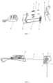
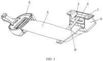
- an intelligent top tether strap structure comprises a fixing member 1, a switch 2, a guide member 3, a connecting member 4, a top tether strap 5, a buckle 6, a first elastic member 7, a second elastic member 8, a reminder device and a cover plate 9.
- the fixing member 1 is fittingly connected to a safety seat body.
- the switch 2, the guide member 3 and the first elastic member 7 are all disposed on the fixing member 1.
- the switch 2 is electrically connected to the reminder device.
- the reminder device can be disposed at any position, provided that the reminder device can implement a reminding function after being disposed.
- the reminder device is a sounding device or a light-emitting device or other somatosensory reminder devices.
- the connecting member 4 is fittingly connected to the guide member 3, and the guide member 3 has a guiding function to define the movement direction of the connecting member 4.
- the first elastic member 7 cooperates with the connecting member 4. When the connecting member 4 is pulled by the top tether strap 5, the first elastic member 7 provides a resilient force, such that the connecting member 4 abuts against the switch 2 when a force of pulling the top tether strap 5 reaches a set value or the connecting member moves to a set position.
- the first elastic member is preferably a spring.
- the cover plate 9 is fittingly connected to the fixing member 1. By configuring the cover plate to fit with the fixing member, the connecting member is protected.
- the connecting member when the top tether strap adopts a forward travelling mode, the connecting member is connected to the buckle by means of the top tether strap.
- the top tether strap is pulled, such that the connecting member is moved.
- the connecting member will contact the switch, and then a reminding message is issued, indicating that the top tether strap has been tightened.
- the fixing member 1 is further provided with a second elastic member 8, and the second elastic member 8 abuts against and presses the connecting member under an external force.
- the pulling force of the top tether strap on the connecting member cannot reach the limit value. Therefore, an additional action of the second elastic member is required to allow the tension force of the top tether strap to reach the limit value.
- the top tether strap is tensioned to apply a force to a fixing plate
- the second elastic member will be subjected to a certain pressure, and when the pressure reaches the limit value, the second elastic member will be pressed against the connecting member, and may contact the switch after being compressed by a certain travel.
Landscapes
- Engineering & Computer Science (AREA)
- Health & Medical Sciences (AREA)
- Child & Adolescent Psychology (AREA)
- General Health & Medical Sciences (AREA)
- Aviation & Aerospace Engineering (AREA)
- Transportation (AREA)
- Mechanical Engineering (AREA)
- Emergency Lowering Means (AREA)
- Seats For Vehicles (AREA)
- Emergency Alarm Devices (AREA)
Claims (6)
- Obere Haltegurtstruktur, umfassend:ein Befestigungselement (1), das mit einem Sicherheitssitzkörper passend verbunden werden kann;ein Verbindungselement (4), einen oberen Haltegurt (5) und eine Schnalle (6), wobei ein Ende des oberen Haltegurts mit der Schnalle verbunden ist und das andere Ende durch das Befestigungselement verläuft und dann mit dem Verbindungselement verbunden ist;dadurch gekennzeichnet, dass es ferner Folgendes umfasst:einen Schalter (2), der an dem Befestigungselement angeordnet ist, wobei das Verbindungselement an dem Schalter anliegt, wenn die Schnalle an dem oberen Haltegurt zieht, um eine Bewegung des Verbindungselements in eine eingestellte Position zu ermöglichen; undeine mit dem Schalter elektrisch verbundene Erinnerungsvorrichtung.
- Obere Haltegurtstruktur nach Anspruch 1, dadurch gekennzeichnet, dass das Befestigungselement (1) mit einem ersten elastischen Element (7) zum Zusammenwirken mit dem Verbindungselement (4) bereitgestellt wird, und wenn eine Zugkraft des oberen Haltegurtes (5) einen eingestellten Wert erreicht, stößt das Verbindungselement gegen die Weiche (2).
- Obere Haltegurtstruktur nach Anspruch 1 oder 2, dadurch gekennzeichnet, dass das Befestigungselement (1) mit einem Führungselement (3) bereitgestellt ist und das Verbindungselement (4) passend mit dem Führungselement verbunden ist.
- Obere Haltegurtstruktur nach Anspruch 3, dadurch gekennzeichnet, dass das Befestigungselement (1) ferner mit einem zweiten elastischen Element (8) bereitgestellt ist und das zweite elastische Element unter einer äußeren Kraft gegen das Verbindungselement (4) stößt und dieses drückt.
- Obere Haltegurtstruktur nach Anspruch 4, dadurch gekennzeichnet, dass die Erinnerungsvorrichtung eine akustische Vorrichtung ist.
- Obere Haltegurtstruktur nach Anspruch 5, dadurch gekennzeichnet, dass das Befestigungselement ferner mit einer Abdeckplatte versehen ist.
Applications Claiming Priority (2)
| Application Number | Priority Date | Filing Date | Title |
|---|---|---|---|
| CN201820141676.6U CN207931541U (zh) | 2018-01-29 | 2018-01-29 | 一种智能上拉带结构 |
| PCT/CN2018/121351 WO2019144729A1 (zh) | 2018-01-29 | 2018-12-15 | 一种智能上拉带结构 |
Publications (4)
| Publication Number | Publication Date |
|---|---|
| EP3702207A1 EP3702207A1 (de) | 2020-09-02 |
| EP3702207A4 EP3702207A4 (de) | 2021-07-21 |
| EP3702207C0 EP3702207C0 (de) | 2025-02-05 |
| EP3702207B1 true EP3702207B1 (de) | 2025-02-05 |
Family
ID=63650283
Family Applications (1)
| Application Number | Title | Priority Date | Filing Date |
|---|---|---|---|
| EP18902106.6A Active EP3702207B1 (de) | 2018-01-29 | 2018-12-15 | Top-tether-gurtstruktur |
Country Status (3)
| Country | Link |
|---|---|
| EP (1) | EP3702207B1 (de) |
| CN (1) | CN207931541U (de) |
| WO (1) | WO2019144729A1 (de) |
Families Citing this family (1)
| Publication number | Priority date | Publication date | Assignee | Title |
|---|---|---|---|---|
| CN207931541U (zh) * | 2018-01-29 | 2018-10-02 | 麦克英孚(宁波)婴童用品有限公司 | 一种智能上拉带结构 |
Citations (1)
| Publication number | Priority date | Publication date | Assignee | Title |
|---|---|---|---|---|
| FR2946582A1 (fr) * | 2009-06-12 | 2010-12-17 | Dorel France Sa | Siege auto pour enfant, destine a equiper un siege de vehicule. |
Family Cites Families (8)
| Publication number | Priority date | Publication date | Assignee | Title |
|---|---|---|---|---|
| FR2853285B1 (fr) * | 2003-04-02 | 2006-04-28 | Ampafrance | Dispositif de liaison d'un siege pour enfant dans un vehicule automobile a indicateur de tension, et siege pour enfant correspondant |
| WO2005120892A2 (en) * | 2004-06-07 | 2005-12-22 | Delphi Technologies, Inc. | Child seat and monitoring system |
| US8235463B2 (en) * | 2010-02-05 | 2012-08-07 | Ford Global Technologies, Llc | Child seat tethering system |
| CN203698007U (zh) * | 2013-12-28 | 2014-07-09 | 麦克英孚(宁波)婴童用品有限公司 | 一种用于车用儿童安全座椅的调节器 |
| CN204978307U (zh) * | 2015-08-28 | 2016-01-20 | 麦克英孚(宁波)婴童用品有限公司 | 一种儿童安全座椅上的安装检测装置 |
| CN205553968U (zh) * | 2016-03-15 | 2016-09-07 | 好孩子儿童用品有限公司 | 一种安全带束缚感应装置及一种儿童汽车安全座椅 |
| CN206067562U (zh) * | 2016-09-29 | 2017-04-05 | 珠海弘点科技有限公司 | 机动车儿童乘员用安全座椅 |
| CN207931541U (zh) * | 2018-01-29 | 2018-10-02 | 麦克英孚(宁波)婴童用品有限公司 | 一种智能上拉带结构 |
-
2018
- 2018-01-29 CN CN201820141676.6U patent/CN207931541U/zh active Active
- 2018-12-15 EP EP18902106.6A patent/EP3702207B1/de active Active
- 2018-12-15 WO PCT/CN2018/121351 patent/WO2019144729A1/zh not_active Ceased
Patent Citations (1)
| Publication number | Priority date | Publication date | Assignee | Title |
|---|---|---|---|---|
| FR2946582A1 (fr) * | 2009-06-12 | 2010-12-17 | Dorel France Sa | Siege auto pour enfant, destine a equiper un siege de vehicule. |
Also Published As
| Publication number | Publication date |
|---|---|
| EP3702207C0 (de) | 2025-02-05 |
| CN207931541U (zh) | 2018-10-02 |
| EP3702207A4 (de) | 2021-07-21 |
| EP3702207A1 (de) | 2020-09-02 |
| WO2019144729A1 (zh) | 2019-08-01 |
Similar Documents
| Publication | Publication Date | Title |
|---|---|---|
| US20040011277A1 (en) | Seat belt tension sensing device | |
| KR200491694Y1 (ko) | 테더벨트 조임 감지 시스템 및 유아 카시트 | |
| CN112829647B (zh) | 儿童安全座椅报警装置 | |
| CN112208405B (zh) | 一种儿童汽车安全座椅 | |
| EP0562740A1 (de) | Sicherheitsgurt-Warnvorrichtung | |
| EP3702207B1 (de) | Top-tether-gurtstruktur | |
| TWI772970B (zh) | 兒童安全座椅警報系統以及兒童安全座椅 | |
| CN208393303U (zh) | 一种织带松紧智能调节器以及使用其的儿童汽车座椅 | |
| JPS62129908U (de) | ||
| US3790994A (en) | Push button buckle | |
| CN202669736U (zh) | 一种汽车安全带报警装置 | |
| CN205553968U (zh) | 一种安全带束缚感应装置及一种儿童汽车安全座椅 | |
| CN205273407U (zh) | 一种安全带使用检测装置 | |
| WO2021012444A1 (zh) | 车载安全提示系统及方法 | |
| CN112208403B (zh) | 一种汽车儿童座椅 | |
| US20100007186A1 (en) | Tension indicator | |
| CN110103876B (zh) | 安全保障系统及具有该安全保障系统的儿童汽车座、汽车 | |
| ATE275058T1 (de) | Verbindungselement für kindsicherheitssitz | |
| US4345238A (en) | Signalling device for use in automotive and like vehicles | |
| CN218316363U (zh) | 一种上拉带的安全警示装置 | |
| EP1692480B1 (de) | Spannungsanzeiger | |
| CN114802096A (zh) | 一种基于微动开关的b面型安全带提醒传感器装置 | |
| CN202574126U (zh) | 一种车载报警装置 | |
| CN113306523A (zh) | 儿童安全座椅及其肩带拉紧提示装置 | |
| CN204077599U (zh) | 一种可显示安全带张紧的显示结构 |
Legal Events
| Date | Code | Title | Description |
|---|---|---|---|
| STAA | Information on the status of an ep patent application or granted ep patent |
Free format text: STATUS: THE INTERNATIONAL PUBLICATION HAS BEEN MADE |
|
| PUAI | Public reference made under article 153(3) epc to a published international application that has entered the european phase |
Free format text: ORIGINAL CODE: 0009012 |
|
| STAA | Information on the status of an ep patent application or granted ep patent |
Free format text: STATUS: REQUEST FOR EXAMINATION WAS MADE |
|
| 17P | Request for examination filed |
Effective date: 20200528 |
|
| AK | Designated contracting states |
Kind code of ref document: A1 Designated state(s): AL AT BE BG CH CY CZ DE DK EE ES FI FR GB GR HR HU IE IS IT LI LT LU LV MC MK MT NL NO PL PT RO RS SE SI SK SM TR |
|
| AX | Request for extension of the european patent |
Extension state: BA ME |
|
| DAV | Request for validation of the european patent (deleted) | ||
| DAX | Request for extension of the european patent (deleted) | ||
| A4 | Supplementary search report drawn up and despatched |
Effective date: 20210616 |
|
| RIC1 | Information provided on ipc code assigned before grant |
Ipc: B60N 2/28 20060101AFI20210611BHEP |
|
| STAA | Information on the status of an ep patent application or granted ep patent |
Free format text: STATUS: EXAMINATION IS IN PROGRESS |
|
| 17Q | First examination report despatched |
Effective date: 20220301 |
|
| REG | Reference to a national code |
Ref country code: DE Ref legal event code: R079 Free format text: PREVIOUS MAIN CLASS: B60N0002280000 Ipc: B60N0002260000 Ref country code: DE Ref legal event code: R079 Ref document number: 602018079000 Country of ref document: DE Free format text: PREVIOUS MAIN CLASS: B60N0002280000 Ipc: B60N0002260000 |
|
| GRAP | Despatch of communication of intention to grant a patent |
Free format text: ORIGINAL CODE: EPIDOSNIGR1 |
|
| STAA | Information on the status of an ep patent application or granted ep patent |
Free format text: STATUS: GRANT OF PATENT IS INTENDED |
|
| RIC1 | Information provided on ipc code assigned before grant |
Ipc: B60N 2/28 20060101ALI20241004BHEP Ipc: B60N 2/26 20060101AFI20241004BHEP |
|
| INTG | Intention to grant announced |
Effective date: 20241017 |
|
| GRAS | Grant fee paid |
Free format text: ORIGINAL CODE: EPIDOSNIGR3 |
|
| GRAA | (expected) grant |
Free format text: ORIGINAL CODE: 0009210 |
|
| STAA | Information on the status of an ep patent application or granted ep patent |
Free format text: STATUS: THE PATENT HAS BEEN GRANTED |
|
| AK | Designated contracting states |
Kind code of ref document: B1 Designated state(s): AL AT BE BG CH CY CZ DE DK EE ES FI FR GB GR HR HU IE IS IT LI LT LU LV MC MK MT NL NO PL PT RO RS SE SI SK SM TR |
|
| REG | Reference to a national code |
Ref country code: GB Ref legal event code: FG4D |
|
| REG | Reference to a national code |
Ref country code: CH Ref legal event code: EP |
|
| REG | Reference to a national code |
Ref country code: DE Ref legal event code: R096 Ref document number: 602018079000 Country of ref document: DE |
|
| REG | Reference to a national code |
Ref country code: IE Ref legal event code: FG4D |
|
| U01 | Request for unitary effect filed |
Effective date: 20250224 |
|
| U07 | Unitary effect registered |
Designated state(s): AT BE BG DE DK EE FI FR IT LT LU LV MT NL PT RO SE SI Effective date: 20250303 |
|
| PG25 | Lapsed in a contracting state [announced via postgrant information from national office to epo] |
Ref country code: RS Free format text: LAPSE BECAUSE OF FAILURE TO SUBMIT A TRANSLATION OF THE DESCRIPTION OR TO PAY THE FEE WITHIN THE PRESCRIBED TIME-LIMIT Effective date: 20250505 |
|
| PG25 | Lapsed in a contracting state [announced via postgrant information from national office to epo] |
Ref country code: PL Free format text: LAPSE BECAUSE OF FAILURE TO SUBMIT A TRANSLATION OF THE DESCRIPTION OR TO PAY THE FEE WITHIN THE PRESCRIBED TIME-LIMIT Effective date: 20250205 |
|
| PG25 | Lapsed in a contracting state [announced via postgrant information from national office to epo] |
Ref country code: ES Free format text: LAPSE BECAUSE OF FAILURE TO SUBMIT A TRANSLATION OF THE DESCRIPTION OR TO PAY THE FEE WITHIN THE PRESCRIBED TIME-LIMIT Effective date: 20250205 |
|
| PG25 | Lapsed in a contracting state [announced via postgrant information from national office to epo] |
Ref country code: IS Free format text: LAPSE BECAUSE OF FAILURE TO SUBMIT A TRANSLATION OF THE DESCRIPTION OR TO PAY THE FEE WITHIN THE PRESCRIBED TIME-LIMIT Effective date: 20250605 Ref country code: NO Free format text: LAPSE BECAUSE OF FAILURE TO SUBMIT A TRANSLATION OF THE DESCRIPTION OR TO PAY THE FEE WITHIN THE PRESCRIBED TIME-LIMIT Effective date: 20250505 |
|
| PG25 | Lapsed in a contracting state [announced via postgrant information from national office to epo] |
Ref country code: HR Free format text: LAPSE BECAUSE OF FAILURE TO SUBMIT A TRANSLATION OF THE DESCRIPTION OR TO PAY THE FEE WITHIN THE PRESCRIBED TIME-LIMIT Effective date: 20250205 |
|
| PG25 | Lapsed in a contracting state [announced via postgrant information from national office to epo] |
Ref country code: GR Free format text: LAPSE BECAUSE OF FAILURE TO SUBMIT A TRANSLATION OF THE DESCRIPTION OR TO PAY THE FEE WITHIN THE PRESCRIBED TIME-LIMIT Effective date: 20250506 |
|
| PG25 | Lapsed in a contracting state [announced via postgrant information from national office to epo] |
Ref country code: SM Free format text: LAPSE BECAUSE OF FAILURE TO SUBMIT A TRANSLATION OF THE DESCRIPTION OR TO PAY THE FEE WITHIN THE PRESCRIBED TIME-LIMIT Effective date: 20250205 |
|
| PG25 | Lapsed in a contracting state [announced via postgrant information from national office to epo] |
Ref country code: CZ Free format text: LAPSE BECAUSE OF FAILURE TO SUBMIT A TRANSLATION OF THE DESCRIPTION OR TO PAY THE FEE WITHIN THE PRESCRIBED TIME-LIMIT Effective date: 20250205 |
|
| PG25 | Lapsed in a contracting state [announced via postgrant information from national office to epo] |
Ref country code: SK Free format text: LAPSE BECAUSE OF FAILURE TO SUBMIT A TRANSLATION OF THE DESCRIPTION OR TO PAY THE FEE WITHIN THE PRESCRIBED TIME-LIMIT Effective date: 20250205 |
|
| U1N | Appointed representative for the unitary patent procedure changed after the registration of the unitary effect |
Representative=s name: SANTARELLI; FR |