EP3702012A1 - Self-cleaning filter - Google Patents
Self-cleaning filter Download PDFInfo
- Publication number
- EP3702012A1 EP3702012A1 EP18871628.6A EP18871628A EP3702012A1 EP 3702012 A1 EP3702012 A1 EP 3702012A1 EP 18871628 A EP18871628 A EP 18871628A EP 3702012 A1 EP3702012 A1 EP 3702012A1
- Authority
- EP
- European Patent Office
- Prior art keywords
- chamber
- blades
- tube
- outlet
- filtering element
- Prior art date
- Legal status (The legal status is an assumption and is not a legal conclusion. Google has not performed a legal analysis and makes no representation as to the accuracy of the status listed.)
- Granted
Links
- 238000004140 cleaning Methods 0.000 title claims abstract description 49
- 238000001914 filtration Methods 0.000 claims abstract description 63
- 239000012530 fluid Substances 0.000 claims abstract description 9
- XLYOFNOQVPJJNP-UHFFFAOYSA-N water Substances O XLYOFNOQVPJJNP-UHFFFAOYSA-N 0.000 claims description 21
- 239000007788 liquid Substances 0.000 claims description 5
- 230000003213 activating effect Effects 0.000 claims description 3
- 238000000926 separation method Methods 0.000 claims 1
- 238000000034 method Methods 0.000 description 7
- 238000012423 maintenance Methods 0.000 description 5
- 238000004519 manufacturing process Methods 0.000 description 5
- 239000007787 solid Substances 0.000 description 5
- 238000011001 backwashing Methods 0.000 description 3
- 238000010408 sweeping Methods 0.000 description 3
- 238000005406 washing Methods 0.000 description 3
- 238000004891 communication Methods 0.000 description 2
- 230000000694 effects Effects 0.000 description 2
- 230000010354 integration Effects 0.000 description 2
- 239000002245 particle Substances 0.000 description 2
- 230000000717 retained effect Effects 0.000 description 2
- 238000013519 translation Methods 0.000 description 2
- 238000006243 chemical reaction Methods 0.000 description 1
- 230000003749 cleanliness Effects 0.000 description 1
- 238000010924 continuous production Methods 0.000 description 1
- 230000005611 electricity Effects 0.000 description 1
- 230000008030 elimination Effects 0.000 description 1
- 238000003379 elimination reaction Methods 0.000 description 1
- 238000005516 engineering process Methods 0.000 description 1
- 238000010348 incorporation Methods 0.000 description 1
- 230000000737 periodic effect Effects 0.000 description 1
- 238000002203 pretreatment Methods 0.000 description 1
- 230000002787 reinforcement Effects 0.000 description 1
- 238000003860 storage Methods 0.000 description 1
- 239000000725 suspension Substances 0.000 description 1
Images


Classifications
-
- B—PERFORMING OPERATIONS; TRANSPORTING
- B01—PHYSICAL OR CHEMICAL PROCESSES OR APPARATUS IN GENERAL
- B01D—SEPARATION
- B01D29/00—Filters with filtering elements stationary during filtration, e.g. pressure or suction filters, not covered by groups B01D24/00 - B01D27/00; Filtering elements therefor
- B01D29/62—Regenerating the filter material in the filter
- B01D29/64—Regenerating the filter material in the filter by scrapers, brushes, nozzles, or the like, acting on the cake side of the filtering element
- B01D29/6407—Regenerating the filter material in the filter by scrapers, brushes, nozzles, or the like, acting on the cake side of the filtering element brushes
- B01D29/6415—Regenerating the filter material in the filter by scrapers, brushes, nozzles, or the like, acting on the cake side of the filtering element brushes with a rotary movement with respect to the filtering element
-
- B—PERFORMING OPERATIONS; TRANSPORTING
- B01—PHYSICAL OR CHEMICAL PROCESSES OR APPARATUS IN GENERAL
- B01D—SEPARATION
- B01D29/00—Filters with filtering elements stationary during filtration, e.g. pressure or suction filters, not covered by groups B01D24/00 - B01D27/00; Filtering elements therefor
- B01D29/11—Filters with filtering elements stationary during filtration, e.g. pressure or suction filters, not covered by groups B01D24/00 - B01D27/00; Filtering elements therefor with bag, cage, hose, tube, sleeve or like filtering elements
- B01D29/31—Self-supporting filtering elements
- B01D29/35—Self-supporting filtering elements arranged for outward flow filtration
-
- B—PERFORMING OPERATIONS; TRANSPORTING
- B01—PHYSICAL OR CHEMICAL PROCESSES OR APPARATUS IN GENERAL
- B01D—SEPARATION
- B01D35/00—Filtering devices having features not specifically covered by groups B01D24/00 - B01D33/00, or for applications not specifically covered by groups B01D24/00 - B01D33/00; Auxiliary devices for filtration; Filter housing constructions
- B01D35/14—Safety devices specially adapted for filtration; Devices for indicating clogging
- B01D35/153—Anti-leakage or anti-return valves
-
- B—PERFORMING OPERATIONS; TRANSPORTING
- B01—PHYSICAL OR CHEMICAL PROCESSES OR APPARATUS IN GENERAL
- B01D—SEPARATION
- B01D35/00—Filtering devices having features not specifically covered by groups B01D24/00 - B01D33/00, or for applications not specifically covered by groups B01D24/00 - B01D33/00; Auxiliary devices for filtration; Filter housing constructions
- B01D35/16—Cleaning-out devices, e.g. for removing the cake from the filter casing or for evacuating the last remnants of liquid
Definitions
- the present invention relates to a self-cleaning filter that enables the cleaning of the filter itself without the incorporation of external or additional elements into the filter itself and without stopping the filtering process.
- Filters are devices intended to retain the dirt of the current of fluid in which it is located, whether it is air or liquid. Due to their own functionality, they require periodic cleaning so that they do not become blocked and continue to operate in a controlled manner, since if the filter becomes dirty, the pressure necessary to make water pass through the filtering means increases, until the filter is completely blocked.
- cleaning is carried out by means of circular nozzles that aspirate the dirt incrusted in the walls of the filter. These nozzles are joined to a shaft which must be externally actuated by a motor so that it moves longitudinally.
- the rotation is caused by the drop in pressure, which makes the water flow through the arm of the shaft to the opposing outlets of the arms in the rear portion of the shaft.
- a fourth type of these self-cleaning filters the cleaning is carried out similarly to the preceding type; circular nozzles that aspirate the dirt incrusted in the walls of the filter are joined to a shaft which is actuated by a single motor. This motor is responsible for providing the shaft with longitudinal movement.
- the rotation is self-actuated, that is, it rotates due to the injectors that carry out the jet propulsion and, due to the action and reaction effect, the cleaning system rotates.
- the present invention resolves these problems that are not resolved in the current state of the art, by means of a self-cleaning filter that does not need to be activated by any external element and where the water loss for cleaning is reduced to a minimum.
- the invention is aligned with the technological filtering solution where several cartridges are introduced in the same pressurised container.
- the invention provides the state of the art with the integration of a self-cleaning system without the presence of motors or external elements. This integration provides the following advantages:
- the invention consists of a self-cleaning filter with a cleaning system that does not need the use of external elements such as electric motors, turbines, pulleys and other accessories to rotate the shaft.
- the self-cleaning filter of the invention is cylinder shaped. It is formed by an outer casing, an inlet cover and an outlet cover. It comprises a liquid inlet mouth with a valve V1 and a liquid outlet mouth with a valve V2, both located in the outer casing, and a drainage outlet with a valve V3 that passes through the outlet cover.
- a cleaning brush configured by means of a tube and blades, is housed inside the supply chamber.
- the tube is fastened at each end, with the ability to rotate, to the inlet disc and to the outlet disc.
- At least two blades are tangentially joined to the tube which are radially distributed in a balanced manner along the length of the tube, with the ends ending with bristles.
- the dimensions of the blades are such that they longitudinally occupy the entire length of the tube and, radially, the bristles are in contact with the filtering element. Both the blades and the tube are hollow and are hydraulically communicated.
- the end of the tube that is located on the outlet disc extends by means of a shaft that does not plug it and ends in a rotor. Both the shaft and the rotor are located in the drainage chamber.
- the operation of the filtering phase is as indicated below.
- the valves V1 and V2 are open, the water accesses the filter through the inlet mouths to the supply chamber and moves to the filtration chamber by passing through the filtering element in order to exit the filter through the outlet mouths.
- valves V1 and V2 When valves V1 and V2 are open, upon opening valve V3, the drainage chamber suctions a portion of the fluid of the filtration chamber, which passes through the filtering element and, through the blades, passes through the tube to move to the drainage chamber, activating the rotor and causing the blades to sweep the inner surface of the filtering element.
- a disc with nozzles can be placed between the outlet disc and the rotor, the nozzles which direct the water jet coming from the tube towards the surface of the vanes of the rotor. The sweeping of the inner surface of the filtering element by the blades and the suction created cause the dirt elements to be detached, which circulate through the tube to move through the drainage outlet to a tank or catch basin.
- the self-cleaning filter of the invention has a cylindrical configuration by means of an outer casing (1) and axial closures configured by means of an inlet cover (16) and an outlet cover (17).
- the filter of the invention incorporates inlet mouths (11) by means of which the water to be filtered accesses the inside of the filter, outlet mouths (12) by means of which the filtered water exits the filter and a drainage outlet (13), which passes through the outlet cover (17), for the storage of the dirt of the filter.
- the supply chamber (2) is located coaxially with the outer casing (1), that is, longitudinally centred in the filter. It is configured in a cylinder shape by means of a filtering element (5) that forms the cylindrical wall that, at one end, rests on an inlet disc (8), configured for the access of water from the inlet mouths (11), and, at the other end, rests on an outlet disc (9) that prevents the passage of water.
- the inlet disc (8) is fastened to the casing (1) and has a hole with the same diameter as the filtering element (5), being closed from the filtering element (5) to the outer casing (1).
- the end of the filtering element (5) comprises radial reinforcements that extend towards the inside of the hole, ending in a circular structure concentric with the filtering element (5).
- the outlet disc (9) it comprises a hole that is also concentric with the filtering element (5).
- a cleaning brush is coaxially located inside the supply chamber (2), which is configured by means of a tube (6) comprising three blades (7) that cover the entire length of the tube (6), each blade (7) being displaced 120 degrees with the contiguous blade (7) such that they have radial symmetry with respect to the tube (6).
- the blades (7) project tangentially from the tube (6), reaching the vicinity of the filtering element (5), thus coming into contact by means of bristles, not shown in the figures, that the ends of the blades (7) incorporate. Despite the contact of the bristles, the relative rotation movement is not affected.
- Both the tube (6) and the blades (7) are hollow and are in communication.
- one end of the tube (6) is closed and ends in a projection (14), while the other end of the tube (6) is open and extends by means of a shaft (15) that ends in a rotor (10).
- a fluid is enabled to circulate between the blades (7) and this end along the tube (6).
- Figure 4 shows the cleaning brush, showing these elements.
- the number of blades (7) has been selected in threes to compromise between production costs and efficiency, such that there may be more blades (7), in this case being displaced a number of degrees resulting from dividing the 360 degree of a complete circle by the number of blades (7).
- the projection (14) is fixed in the circular structure of the inlet disc (8) while the tube itself (6) passes through the hole of the outlet disc (9).
- the joins of the tube (6) with the discs (8, 9) provide the tube (6) with the ability to rotate. This ability to rotate is necessary so that the blades (7) act on the entire inner surface of the filtering element (5), which is where the solids retained in the filtering process accumulate, causing a complete cleaning of the filtering element (5).
- the symmetrical arrangement of the blades (7) means that the weight is balanced and the rotation of the tube (6) is caused more easily.
- the joins between the projection (14) and the tube (6) with inlet (8) and outlet (9) discs incorporate common elements of the state of the art to facilitate both relative movement and leak-tightness.
- FIG 3 shows an enlargement of the area of the filter corresponding to the drainage chamber (4).
- the drainage chamber (4) is configured in the shape of a cylindrical tube that is joined at one of the ends thereof to the outlet disc (9) of the supply chamber (2), being axially closed, with the exception of the hole through which the tube (6) passes, the shaft (15) and the rotor (10) being in the drainage chamber (4).
- the join of the drainage chamber (4) with the supply chamber (2) is carried out by means of a flap element that incorporates elements for fastening to the casing (1).
- the other end of the drainage chamber (4) incorporates a drainage outlet (13) that passes through the outlet cover (17) and communicates with a tank for storing dirt.
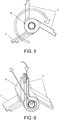
- the drainage chamber (4) is located adjacent to the supply chamber (2) from where one of the ends of the tube (6) extends to enter the drainage chamber (4) by means of the shaft (15), ending in a rotor (10).
- a rotor (10) In this way, when the water passes from the supply chamber (2), through the blades (7) and the tube (6), to the drainage chamber (4) it meets the rotor (10), making it rotate and causing the rotation of the tube (6), as shown in figure 5 and, as a result, the sweeping movement of the blades (7) along the filtering element (5).
- the circulation movement of the water along the blades (7) and the tube (6) is shown in figure 6 .
- the operation of the rotor (10) can be improved by inserting, between the outlet disc (9) and the rotor (10), a disc that, on the side of the outlet disc (9), has openings and, on the side of the rotor (10), has nozzles (18) that point towards the vanes of the rotor (10). In this way, the fluid is forced to move from the outlet of the tube (6) towards the nozzles (18) and thus hit more directionally on the vanes of the rotor (10).
- the outlet disc (9) comprises holes joined to nozzles (18) which are radially distributed and directed towards the surface of vanes of the rotor (10).
- the filtration chamber (3) is delimited by the outer surface of the filtering element (5), and of the casing of the drainage chamber (4), the inner surface of the casing (1), the inlet disc (8) and the outlet cover (17), having direct access to the outlet mouths (12) of the filter. In this way, it surrounds the supply chamber (2), separated from the same by means of the filtering element (5), and the drainage chamber (4).
- the filtration chamber (3) contains the water that has passed through the filtering element (5) and no longer contains solid particles greater than the micronage of the sieve of the filtering element (5).
- the filter has a series of valves that control the operation that, although they have not been shown in the figures, have been referred to as V1, V2 and V3 for greater ease when writing the description.
- V1, V2 and V3 for greater ease when writing the description.
- each of the inlet mouths (11) incorporates a valve V1
- each outlet mouth incorporates a valve V2
- the drainage outlet (13) of the drainage chamber (4) incorporates a valve V3.
- valves V1 and V2 remain open, while the valve V3 remains closed.
- the water enters the supply chamber (2) of the filter through the valves V1 of the inlet mouths (11) and, as the valve V3 of the drainage outlet (13) is closed, it is forced to pass through the filtering element (5) from the inside to the outside in order to access the filtration chamber (3).
- the solids in suspension with a size greater than the value predetermined by the sieve of the filtering element (5) are retained on the inner surface of the filtering element (5), while the rest accesses the filtration chamber (3) with the flow of water to subsequently exit to the outside of the filter through the outlet mouths (12) through the valves V2.
- the sieve tends to be selected between 100 and 500 micron.
- the backwashing process entails cleaning the filtering element (5).
- This process is activated upon determining that there is a specific pressure difference between the supply chamber (2) and the filtration chamber (3).
- This specific value corresponds to a level of dirt which is considered critical which makes it necessary to clean the filtering element (5).
- it is manually determined by means of adjusting a differential manometer.
- the valves V1 and V2 being open, valve V3 of the drainage outlet (13) is opened, then activating the hydraulic communication of the supply chamber (2), through the tube (6), with the drainage chamber (4) and generating suction of the supply chamber (2) from the drainage chamber (4).
- the suction is generated due to the fact that the pressure outside the valve V3, in the drainage chamber (4), is atmospheric pressure, while the supply chamber (2) and, therefore, the tube (6), with water circulation, is at values usually greater than 3 bars.
- the suction from the supply chamber (2) to the drainage chamber (4) is produced through the inside of the tube (6), which suctions, through the cavities inside the three blades (7), the dirt accumulated on the inner face of the filtering element (5).
- the cleaning of the filter is carried out by means of two systems. Firstly, the bristles of the suction blades (7) brush the surface of the filtering element (5) to detach the solids adhered to the inner wall. Secondly, the three hollow blades (7) suction the solid particles that have been previously detached through the tube (6), due to the effect of the pressure difference with the outside.
Landscapes
- Chemical & Material Sciences (AREA)
- Chemical Kinetics & Catalysis (AREA)
- Filtration Of Liquid (AREA)
Abstract
Description
- The present invention relates to a self-cleaning filter that enables the cleaning of the filter itself without the incorporation of external or additional elements into the filter itself and without stopping the filtering process.
- It has a particular application in the industrial field relating to the manufacture of filters.
- Filters are devices intended to retain the dirt of the current of fluid in which it is located, whether it is air or liquid. Due to their own functionality, they require periodic cleaning so that they do not become blocked and continue to operate in a controlled manner, since if the filter becomes dirty, the pressure necessary to make water pass through the filtering means increases, until the filter is completely blocked.
- In order to prevent the filter removal process, with the resulting problems due to stopping the production, there are a variety of self-cleaning filters that are known in the current state of the art. These filters incorporate a device intended to clean the filter itself without requiring the removal thereof.
- In a first type of these self-cleaning filters, cleaning is carried out by means of rotation, actuated by a motor, of a plunger tube that aspirates the inside of the filtering elements (strainers). Due to this suction, the dirt incrusted in the walls of the filtering elements is eliminated. The suction is produced by the drop in pressure, which makes the water flow through the arm to the outlets of the valve in the lowest portion of the equipment. This cleaning system does not have axial movement, only rotational.
- In a second type of these self-cleaning filters, cleaning is carried out by means of circular nozzles that aspirate the dirt incrusted in the walls of the filter. These nozzles are joined to a shaft which must be externally actuated by a motor so that the shaft moves longitudinally. The rotation is caused by the drop in pressure, which makes the water flow through the arm of the shaft to the opposing outlets of the arms in the rear portion of the shaft.
- In a third type of these self-cleaning filters, cleaning is carried out by means of circular nozzles that aspirate the dirt incrusted in the walls of the filter. These nozzles are joined to a shaft which must be externally actuated by a motor so that it moves longitudinally.
- The rotation is caused by the drop in pressure, which makes the water flow through the arm of the shaft to the opposing outlets of the arms in the rear portion of the shaft.
- In a fourth type of these self-cleaning filters, the cleaning is carried out similarly to the preceding type; circular nozzles that aspirate the dirt incrusted in the walls of the filter are joined to a shaft which is actuated by a single motor. This motor is responsible for providing the shaft with longitudinal movement. In this last case, the rotation is self-actuated, that is, it rotates due to the injectors that carry out the jet propulsion and, due to the action and reaction effect, the cleaning system rotates.
- However, all these self-cleaning filters have a series of drawbacks, such as:
- Maintenance of the motor.
- Maintenance due to wear of the mobile parts.
- Greater loss of water to ensure 100% cleanliness of the mesh.
- In this way, although the self-cleaning filters have been used for decades, this technology still presents a series of aspects to be improved and even resolved, such as:
- Operation without the use of a motor to make the rotor rotate.
- Operation without the use of a motor for the horizontal translation movement and the piston, reducing the maintenance and cost.
- The fact that the aspiration mouths do not pass over 100% of the surface of the strainer, or pass over only once.
- The high water loss during washing.
- The present invention resolves these problems that are not resolved in the current state of the art, by means of a self-cleaning filter that does not need to be activated by any external element and where the water loss for cleaning is reduced to a minimum.
- The invention is aligned with the technological filtering solution where several cartridges are introduced in the same pressurised container.
- The invention provides the state of the art with the integration of a self-cleaning system without the presence of motors or external elements. This integration provides the following advantages:
- it ensures that the aspiration mouths pass over 100% of the surface of the filtering element and, also, repetitively, during cleaning. It must be noted that current devices cannot ensure the sweeping of 100% of the area since it depends on the ratio between translation and rotation speeds. Moreover, they only pass over once, so the washing has worse performance.
- Water loss during washing is negligible, less than 5 m3/h in the majority of cases,
- The floor area (footprint) and the number of pre-treatment elements (fewer bodies, fewer valves, fewer control elements, etc.) is reduced,
- Maintenance times of the equipment are reduced given that the number of objects susceptible to maintenance are significantly reduced. Stopped equipment always entails losses for the plant.
- Load loss of the system is reduced as accessories are removed, which improves the energy efficiency of the plant.
- Noise, pollution and electricity consumption are reduced since there is no motor to carry out the cleaning of the equipment.
- Elements are used that enable continuous production while the autonomous cleaning of the filter is carried out, without the need to stop production, resulting in the elimination of losses for the plant.
- The invention consists of a self-cleaning filter with a cleaning system that does not need the use of external elements such as electric motors, turbines, pulleys and other accessories to rotate the shaft.
- It is a system that is self-actuated by hydraulic propulsion that enables cleaning to be carried out while the equipment is filtering, without having to stop production. To do so, there is a minor drawback, which is that when the cleaning takes place, a minimal amount of the supply flow is sent to drainage.
- The self-cleaning filter of the invention is cylinder shaped. It is formed by an outer casing, an inlet cover and an outlet cover. It comprises a liquid inlet mouth with a valve V1 and a liquid outlet mouth with a valve V2, both located in the outer casing, and a drainage outlet with a valve V3 that passes through the outlet cover.
- There are three chambers inside the filter of the invention:
- a supply chamber, which is coaxial with the outer casing, configured by means of a filtering element by way of a cylindrical surface that is joined at the ends to an inlet disc and to an outlet disc by way of bases,
- a drainage chamber that is joined to the supply chamber at one end and to a drainage outlet at the other end, and
- a filtration chamber, surrounding the supply chamber and the drainage chamber and limited by the outer casing, the inlet disc and the outlet disc.
- A cleaning brush, configured by means of a tube and blades, is housed inside the supply chamber. The tube is fastened at each end, with the ability to rotate, to the inlet disc and to the outlet disc. At least two blades are tangentially joined to the tube which are radially distributed in a balanced manner along the length of the tube, with the ends ending with bristles. The dimensions of the blades are such that they longitudinally occupy the entire length of the tube and, radially, the bristles are in contact with the filtering element. Both the blades and the tube are hollow and are hydraulically communicated.
- The end of the tube that is located on the outlet disc extends by means of a shaft that does not plug it and ends in a rotor. Both the shaft and the rotor are located in the drainage chamber.
- The operation of the filtering phase is as indicated below. When the valves V1 and V2 are open, the water accesses the filter through the inlet mouths to the supply chamber and moves to the filtration chamber by passing through the filtering element in order to exit the filter through the outlet mouths.
- The operation of the cleaning phase is the following. When valves V1 and V2 are open, upon opening valve V3, the drainage chamber suctions a portion of the fluid of the filtration chamber, which passes through the filtering element and, through the blades, passes through the tube to move to the drainage chamber, activating the rotor and causing the blades to sweep the inner surface of the filtering element. Furthermore, in order to improve the effectiveness of the movement of the cleaning brush, a disc with nozzles can be placed between the outlet disc and the rotor, the nozzles which direct the water jet coming from the tube towards the surface of the vanes of the rotor. The sweeping of the inner surface of the filtering element by the blades and the suction created cause the dirt elements to be detached, which circulate through the tube to move through the drainage outlet to a tank or catch basin.
- To complete the description of the invention, and for the purpose of helping to make the characteristics thereof more readily understandable, according to a preferred exemplary embodiment thereof, a set of drawings is included where, by way of illustration and not limitation, the following figures have been represented:
-
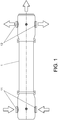
Figure 1 shows a side view of the self-cleaning filter of the invention. -
Figure 2 shows a longitudinal cross-sectional view of the filter offigure 1 . -
Figure 3 shows an enlargement of the outlet area of the filter shown infigure 2 . -
Figure 4 shows a perspective view of the cleaning brush. -
Figure 5 shows a front view of the cleaning brush showing the direction of movement of the blades. -
Figure 6 shows a cross-sectional perspective view of the cleaning brush showing the direction of the fluid during the cleaning process. - A list of the references used in the figures is provided below:
- 1. Outer casing.
- 2. Supply chamber.
- 3. Filtration chamber.
- 4. Drainage chamber.
- 5. Filtering element.
- 6. Tube.
- 7. Blades.
- 8. Inlet disc.
- 9. Outlet disc.
- 10. Rotor.
- 11. Inlet mouth.
- 12. Outlet mouth.
- 13. Drainage outlet.
- 14. Projection.
- 15. Shaft.
- 16. Inlet cover.
- 17. Outlet cover.
- 18. Nozzles.
- Pursuant to the numbering used in the figures, as shown in
figures 1 and2 , the self-cleaning filter of the invention has a cylindrical configuration by means of an outer casing (1) and axial closures configured by means of an inlet cover (16) and an outlet cover (17). The filter of the invention incorporates inlet mouths (11) by means of which the water to be filtered accesses the inside of the filter, outlet mouths (12) by means of which the filtered water exits the filter and a drainage outlet (13), which passes through the outlet cover (17), for the storage of the dirt of the filter. There are three areas inside the filter that are clearly differentiated depending on the filtration status of the fluid. These areas are the supply chamber (2), filtration chamber (3) and drainage chamber (4). - The supply chamber (2) is located coaxially with the outer casing (1), that is, longitudinally centred in the filter. It is configured in a cylinder shape by means of a filtering element (5) that forms the cylindrical wall that, at one end, rests on an inlet disc (8), configured for the access of water from the inlet mouths (11), and, at the other end, rests on an outlet disc (9) that prevents the passage of water. The inlet disc (8) is fastened to the casing (1) and has a hole with the same diameter as the filtering element (5), being closed from the filtering element (5) to the outer casing (1). The end of the filtering element (5) comprises radial reinforcements that extend towards the inside of the hole, ending in a circular structure concentric with the filtering element (5). As for the outlet disc (9), it comprises a hole that is also concentric with the filtering element (5).
- A cleaning brush is coaxially located inside the supply chamber (2), which is configured by means of a tube (6) comprising three blades (7) that cover the entire length of the tube (6), each blade (7) being displaced 120 degrees with the contiguous blade (7) such that they have radial symmetry with respect to the tube (6). The blades (7) project tangentially from the tube (6), reaching the vicinity of the filtering element (5), thus coming into contact by means of bristles, not shown in the figures, that the ends of the blades (7) incorporate. Despite the contact of the bristles, the relative rotation movement is not affected. Both the tube (6) and the blades (7) are hollow and are in communication. Moreover, one end of the tube (6) is closed and ends in a projection (14), while the other end of the tube (6) is open and extends by means of a shaft (15) that ends in a rotor (10). In this way, a fluid is enabled to circulate between the blades (7) and this end along the tube (6).
Figure 4 shows the cleaning brush, showing these elements. - The number of blades (7) has been selected in threes to compromise between production costs and efficiency, such that there may be more blades (7), in this case being displaced a number of degrees resulting from dividing the 360 degree of a complete circle by the number of blades (7).
- In order to fix the tube (6) inside the supply chamber (2), the projection (14) is fixed in the circular structure of the inlet disc (8) while the tube itself (6) passes through the hole of the outlet disc (9). The joins of the tube (6) with the discs (8, 9) provide the tube (6) with the ability to rotate. This ability to rotate is necessary so that the blades (7) act on the entire inner surface of the filtering element (5), which is where the solids retained in the filtering process accumulate, causing a complete cleaning of the filtering element (5). The symmetrical arrangement of the blades (7) means that the weight is balanced and the rotation of the tube (6) is caused more easily. The joins between the projection (14) and the tube (6) with inlet (8) and outlet (9) discs incorporate common elements of the state of the art to facilitate both relative movement and leak-tightness.
-
Figure 3 shows an enlargement of the area of the filter corresponding to the drainage chamber (4). The drainage chamber (4) is configured in the shape of a cylindrical tube that is joined at one of the ends thereof to the outlet disc (9) of the supply chamber (2), being axially closed, with the exception of the hole through which the tube (6) passes, the shaft (15) and the rotor (10) being in the drainage chamber (4). The join of the drainage chamber (4) with the supply chamber (2) is carried out by means of a flap element that incorporates elements for fastening to the casing (1). The other end of the drainage chamber (4) incorporates a drainage outlet (13) that passes through the outlet cover (17) and communicates with a tank for storing dirt. - The drainage chamber (4) is located adjacent to the supply chamber (2) from where one of the ends of the tube (6) extends to enter the drainage chamber (4) by means of the shaft (15), ending in a rotor (10). In this way, when the water passes from the supply chamber (2), through the blades (7) and the tube (6), to the drainage chamber (4) it meets the rotor (10), making it rotate and causing the rotation of the tube (6), as shown in
figure 5 and, as a result, the sweeping movement of the blades (7) along the filtering element (5). The circulation movement of the water along the blades (7) and the tube (6) is shown infigure 6 . - The operation of the rotor (10) can be improved by inserting, between the outlet disc (9) and the rotor (10), a disc that, on the side of the outlet disc (9), has openings and, on the side of the rotor (10), has nozzles (18) that point towards the vanes of the rotor (10). In this way, the fluid is forced to move from the outlet of the tube (6) towards the nozzles (18) and thus hit more directionally on the vanes of the rotor (10).
- Alternatively, the outlet disc (9) comprises holes joined to nozzles (18) which are radially distributed and directed towards the surface of vanes of the rotor (10).
- The filtration chamber (3) is delimited by the outer surface of the filtering element (5), and of the casing of the drainage chamber (4), the inner surface of the casing (1), the inlet disc (8) and the outlet cover (17), having direct access to the outlet mouths (12) of the filter. In this way, it surrounds the supply chamber (2), separated from the same by means of the filtering element (5), and the drainage chamber (4). The filtration chamber (3) contains the water that has passed through the filtering element (5) and no longer contains solid particles greater than the micronage of the sieve of the filtering element (5).
- In addition to the elements described, the filter has a series of valves that control the operation that, although they have not been shown in the figures, have been referred to as V1, V2 and V3 for greater ease when writing the description. In this way, each of the inlet mouths (11) incorporates a valve V1, each outlet mouth incorporates a valve V2, and the drainage outlet (13) of the drainage chamber (4) incorporates a valve V3.
- In general, the operation of the filter of the invention can be broken down into the following phases:
- During the filtration process, the valves V1 and V2 remain open, while the valve V3 remains closed. In this way, the water enters the supply chamber (2) of the filter through the valves V1 of the inlet mouths (11) and, as the valve V3 of the drainage outlet (13) is closed, it is forced to pass through the filtering element (5) from the inside to the outside in order to access the filtration chamber (3). The solids in suspension with a size greater than the value predetermined by the sieve of the filtering element (5) are retained on the inner surface of the filtering element (5), while the rest accesses the filtration chamber (3) with the flow of water to subsequently exit to the outside of the filter through the outlet mouths (12) through the valves V2. The sieve tends to be selected between 100 and 500 micron.
- The backwashing process entails cleaning the filtering element (5). This process is activated upon determining that there is a specific pressure difference between the supply chamber (2) and the filtration chamber (3). This specific value corresponds to a level of dirt which is considered critical which makes it necessary to clean the filtering element (5). In the exemplary embodiment, it is manually determined by means of adjusting a differential manometer. In order to activate the backwashing process, the valves V1 and V2 being open, valve V3 of the drainage outlet (13) is opened, then activating the hydraulic communication of the supply chamber (2), through the tube (6), with the drainage chamber (4) and generating suction of the supply chamber (2) from the drainage chamber (4). The suction is generated due to the fact that the pressure outside the valve V3, in the drainage chamber (4), is atmospheric pressure, while the supply chamber (2) and, therefore, the tube (6), with water circulation, is at values usually greater than 3 bars.
- The suction from the supply chamber (2) to the drainage chamber (4) is produced through the inside of the tube (6), which suctions, through the cavities inside the three blades (7), the dirt accumulated on the inner face of the filtering element (5). The cleaning of the filter is carried out by means of two systems. Firstly, the bristles of the suction blades (7) brush the surface of the filtering element (5) to detach the solids adhered to the inner wall. Secondly, the three hollow blades (7) suction the solid particles that have been previously detached through the tube (6), due to the effect of the pressure difference with the outside.
- Lastly, it must be noted that the present invention must not be limited to the embodiment described herein. Other configurations may be carried out by those skilled in the art based on the present description. Accordingly, the scope of the invention is defined by the following claims.
Claims (5)
- A self-cleaning filter with a cylindrical configuration comprising an outer casing (1) by way of cylindrical surface, an inlet cover (16) and an outlet cover (17) by way of bases, a liquid inlet mouth (11) with a valve V1, a liquid outlet mouth (12) with a valve V2 and a drainage outlet (13) with a valve V3, the filter being characterized in that it comprises:- a supply chamber (2), which is coaxial with the cylindrical-shaped outer casing (1), configured by means of a filtering element (5) by way of a cylindrical surface that is joined to an inlet disc (8) and to an outlet disc (9) by way of bases,- a drainage chamber (4) that is joined to the supply chamber (2) at one end and to a drainage outlet (13) at the other end,- a filtration chamber (3), delimited between the outer casing (1), the supply chamber (2) and drainage chamber (4), the inlet disc (8) and the outlet cover (17),wherein,- the supply chamber (2) comprises a tube (6) that is fixed, with the ability to rotate, to the inlet disc (8) and to the outlet disc (9), at least two blades (7) extending tangentially from the tube (6), with the ends ending with bristles, having dimensions such that they longitudinally occupy the entire length of the tube (6) and, radially, the bristles are in contact with the filtering element (5), the blades (7) being radially distributed in a balanced manner, and both the blades (7) and tube (6) being hollow and hydraulically communicated,- the drainage chamber houses a shaft (15), joined to, and without plugging, the end of the tube (6), the shaft (15) ending in a rotor (10)such that:- when the valves V1 and V2 are open, the water enters into the supply chamber (2) and moves to the filtering chamber (3) passing through the filtering element (5), and- when the valves V1, V2 and V3 are open, the drainage chamber (4) suctions the fluid of the filtration chamber (3), which passes through the filtering element (5) and, through the blades (7), passes through the tube (6) to move to the drainage chamber (4), activating the rotor (10) and making the blades (7) sweep the inner surface of the filtering element (5).
- The self-cleaning filter according to claim 1, characterized in that the cleaning brush comprises three blades (7) distributed radially with a separation of 120 degrees.
- The self-cleaning filter according to claim 1, characterized in that the total length of the blades (7) is greater than the length of the tube (6), the blades (7) overlapping slightly, such that it is ensured that they access the entire surface of the filtering element (5).
- The self-cleaning filter according to any of claims 1 or 2, characterized in that between the outlet disc (9) and the rotor (10), the drainage chamber (4) is blocked by a disc with holes joined to nozzles (18) directed towards vanes of the rotor (10) through which the fluid is forced to move.
- The self-cleaning filter according to any of claims 1 to 3, characterized in that the outlet disc (9) comprises holes joined to nozzles (18) which are radially distributed and directed towards the surface of vanes of the rotor (10).
Applications Claiming Priority (2)
| Application Number | Priority Date | Filing Date | Title |
|---|---|---|---|
| ES201731305U ES1199133Y (en) | 2017-10-27 | 2017-10-27 | SELF CLEANING FILTER |
| PCT/ES2018/070660 WO2019081790A1 (en) | 2017-10-27 | 2018-10-10 | Self-cleaning filter |
Publications (3)
| Publication Number | Publication Date |
|---|---|
| EP3702012A1 true EP3702012A1 (en) | 2020-09-02 |
| EP3702012A4 EP3702012A4 (en) | 2020-11-18 |
| EP3702012B1 EP3702012B1 (en) | 2021-07-28 |
Family
ID=60324195
Family Applications (1)
| Application Number | Title | Priority Date | Filing Date |
|---|---|---|---|
| EP18871628.6A Active EP3702012B1 (en) | 2017-10-27 | 2018-10-10 | Self-cleaning filter |
Country Status (3)
| Country | Link |
|---|---|
| EP (1) | EP3702012B1 (en) |
| ES (2) | ES1199133Y (en) |
| WO (1) | WO2019081790A1 (en) |
Families Citing this family (2)
| Publication number | Priority date | Publication date | Assignee | Title |
|---|---|---|---|---|
| ES1262885Y (en) | 2020-12-23 | 2021-06-07 | Fluytec S A | OPTIMIZED SELF-CLEANING FILTER |
| CN114797231B (en) * | 2022-04-22 | 2023-08-25 | 华能伊敏煤电有限责任公司 | Outdoor conveying adhesive tape anti-freezing equipment in alpine region |
Family Cites Families (5)
| Publication number | Priority date | Publication date | Assignee | Title |
|---|---|---|---|---|
| GB1485989A (en) * | 1975-05-23 | 1977-09-14 | Plenty Group Ltd | Filter with backflushing device |
| FR2578441B1 (en) * | 1985-03-05 | 1989-10-20 | Assainissement Distr Ste Gle | SELF-CLEANING FILTER |
| WO1999033542A1 (en) * | 1997-12-23 | 1999-07-08 | Ontario Hydro | Filter system |
| DE202011000268U1 (en) * | 2011-02-04 | 2012-05-16 | Boll & Kirch Filterbau Gmbh | Backwash filter with rinsing device |
| CN108379921A (en) * | 2016-06-16 | 2018-08-10 | 徐嘉 | A kind of ceramic element water purifier |
-
2017
- 2017-10-27 ES ES201731305U patent/ES1199133Y/en not_active Expired - Fee Related
-
2018
- 2018-10-10 ES ES18871628T patent/ES2890400T3/en active Active
- 2018-10-10 WO PCT/ES2018/070660 patent/WO2019081790A1/en active Search and Examination
- 2018-10-10 EP EP18871628.6A patent/EP3702012B1/en active Active
Also Published As
| Publication number | Publication date |
|---|---|
| EP3702012B1 (en) | 2021-07-28 |
| EP3702012A4 (en) | 2020-11-18 |
| ES1199133Y (en) | 2018-02-23 |
| WO2019081790A1 (en) | 2019-05-02 |
| ES1199133U (en) | 2017-11-21 |
| ES2890400T3 (en) | 2022-01-19 |
Similar Documents
| Publication | Publication Date | Title |
|---|---|---|
| US8733375B2 (en) | Water conducting household appliance | |
| EP3026166B1 (en) | Circulating drainage apparatus and household appliance | |
| EP2767321B1 (en) | Self-cleaning filter | |
| EP0429409B1 (en) | Self-cleaning filter for hydraulic systems fitted with an hydraulic turbine which operates a number of cleaning brushes | |
| JP6059283B2 (en) | Filtration unit | |
| KR100538306B1 (en) | Self-cleaning filtering system | |
| EP3702012B1 (en) | Self-cleaning filter | |
| CN106039820B (en) | Sea water filter before a kind of centrifugal backwashing pump | |
| KR20130107907A (en) | A filter element with rotor blades and a filtering device with the same | |
| EP1844833B1 (en) | Self-cleaning filter for agricultural irrigation water | |
| JPH0440046B2 (en) | ||
| CN107970665A (en) | A kind of Full-automatic self-cleaning filter | |
| KR100630372B1 (en) | Filtering Device | |
| CN202590464U (en) | Self-cleaning filter device for multiple stages of strainers | |
| KR101952310B1 (en) | Inside tube percolator | |
| CN214693835U (en) | Sludge separating pump | |
| KR20100000395A (en) | Auto screen washing type's filtering apparatus using fluis pressure | |
| KR101820959B1 (en) | Filtration System with Real-time Cleaning Function | |
| KR100257861B1 (en) | Automatic filter | |
| CN109745761A (en) | A kind of drainage arrangement and its control method | |
| CN110292793A (en) | A kind of self-cleaning oil removal filter | |
| CN213285855U (en) | Horizontal hydraulic drive filter | |
| CN114197174B (en) | Washing machine | |
| CN112811773A (en) | Sludge separation pump and use method thereof | |
| RU145027U1 (en) | CENTRIFUGAL FILTER DEVICE |
Legal Events
| Date | Code | Title | Description |
|---|---|---|---|
| STAA | Information on the status of an ep patent application or granted ep patent |
Free format text: STATUS: THE INTERNATIONAL PUBLICATION HAS BEEN MADE |
|
| PUAI | Public reference made under article 153(3) epc to a published international application that has entered the european phase |
Free format text: ORIGINAL CODE: 0009012 |
|
| STAA | Information on the status of an ep patent application or granted ep patent |
Free format text: STATUS: REQUEST FOR EXAMINATION WAS MADE |
|
| 17P | Request for examination filed |
Effective date: 20200305 |
|
| AK | Designated contracting states |
Kind code of ref document: A1 Designated state(s): AL AT BE BG CH CY CZ DE DK EE ES FI FR GB GR HR HU IE IS IT LI LT LU LV MC MK MT NL NO PL PT RO RS SE SI SK SM TR |
|
| AX | Request for extension of the european patent |
Extension state: BA ME |
|
| A4 | Supplementary search report drawn up and despatched |
Effective date: 20201019 |
|
| RIC1 | Information provided on ipc code assigned before grant |
Ipc: B01D 35/153 20060101ALI20201013BHEP Ipc: B01D 35/16 20060101ALI20201013BHEP Ipc: B01D 29/64 20060101AFI20201013BHEP Ipc: B01D 29/35 20060101ALI20201013BHEP |
|
| RIC1 | Information provided on ipc code assigned before grant |
Ipc: B01D 35/153 20060101ALI20201103BHEP Ipc: B01D 35/16 20060101ALI20201103BHEP Ipc: B01D 29/64 20060101AFI20201103BHEP Ipc: B01D 29/35 20060101ALI20201103BHEP |
|
| RIN1 | Information on inventor provided before grant (corrected) |
Inventor name: MESA CUEVAS, UNAI Inventor name: OTEGUI MARTINEZ, PEDRO |
|
| DAV | Request for validation of the european patent (deleted) | ||
| DAX | Request for extension of the european patent (deleted) | ||
| GRAP | Despatch of communication of intention to grant a patent |
Free format text: ORIGINAL CODE: EPIDOSNIGR1 |
|
| STAA | Information on the status of an ep patent application or granted ep patent |
Free format text: STATUS: GRANT OF PATENT IS INTENDED |
|
| INTG | Intention to grant announced |
Effective date: 20210421 |
|
| GRAS | Grant fee paid |
Free format text: ORIGINAL CODE: EPIDOSNIGR3 |
|
| GRAA | (expected) grant |
Free format text: ORIGINAL CODE: 0009210 |
|
| STAA | Information on the status of an ep patent application or granted ep patent |
Free format text: STATUS: THE PATENT HAS BEEN GRANTED |
|
| AK | Designated contracting states |
Kind code of ref document: B1 Designated state(s): AL AT BE BG CH CY CZ DE DK EE ES FI FR GB GR HR HU IE IS IT LI LT LU LV MC MK MT NL NO PL PT RO RS SE SI SK SM TR |
|
| REG | Reference to a national code |
Ref country code: GB Ref legal event code: FG4D |
|
| REG | Reference to a national code |
Ref country code: CH Ref legal event code: EP |
|
| REG | Reference to a national code |
Ref country code: DE Ref legal event code: R096 Ref document number: 602018021001 Country of ref document: DE |
|
| REG | Reference to a national code |
Ref country code: AT Ref legal event code: REF Ref document number: 1414185 Country of ref document: AT Kind code of ref document: T Effective date: 20210815 |
|
| REG | Reference to a national code |
Ref country code: IE Ref legal event code: FG4D |
|
| REG | Reference to a national code |
Ref country code: LT Ref legal event code: MG9D |
|
| REG | Reference to a national code |
Ref country code: NL Ref legal event code: MP Effective date: 20210728 |
|
| REG | Reference to a national code |
Ref country code: AT Ref legal event code: MK05 Ref document number: 1414185 Country of ref document: AT Kind code of ref document: T Effective date: 20210728 |
|
| REG | Reference to a national code |
Ref country code: ES Ref legal event code: FG2A Ref document number: 2890400 Country of ref document: ES Kind code of ref document: T3 Effective date: 20220119 |
|
| PG25 | Lapsed in a contracting state [announced via postgrant information from national office to epo] |
Ref country code: FI Free format text: LAPSE BECAUSE OF FAILURE TO SUBMIT A TRANSLATION OF THE DESCRIPTION OR TO PAY THE FEE WITHIN THE PRESCRIBED TIME-LIMIT Effective date: 20210728 Ref country code: RS Free format text: LAPSE BECAUSE OF FAILURE TO SUBMIT A TRANSLATION OF THE DESCRIPTION OR TO PAY THE FEE WITHIN THE PRESCRIBED TIME-LIMIT Effective date: 20210728 Ref country code: SE Free format text: LAPSE BECAUSE OF FAILURE TO SUBMIT A TRANSLATION OF THE DESCRIPTION OR TO PAY THE FEE WITHIN THE PRESCRIBED TIME-LIMIT Effective date: 20210728 Ref country code: LT Free format text: LAPSE BECAUSE OF FAILURE TO SUBMIT A TRANSLATION OF THE DESCRIPTION OR TO PAY THE FEE WITHIN THE PRESCRIBED TIME-LIMIT Effective date: 20210728 Ref country code: AT Free format text: LAPSE BECAUSE OF FAILURE TO SUBMIT A TRANSLATION OF THE DESCRIPTION OR TO PAY THE FEE WITHIN THE PRESCRIBED TIME-LIMIT Effective date: 20210728 Ref country code: BG Free format text: LAPSE BECAUSE OF FAILURE TO SUBMIT A TRANSLATION OF THE DESCRIPTION OR TO PAY THE FEE WITHIN THE PRESCRIBED TIME-LIMIT Effective date: 20211028 Ref country code: HR Free format text: LAPSE BECAUSE OF FAILURE TO SUBMIT A TRANSLATION OF THE DESCRIPTION OR TO PAY THE FEE WITHIN THE PRESCRIBED TIME-LIMIT Effective date: 20210728 Ref country code: NO Free format text: LAPSE BECAUSE OF FAILURE TO SUBMIT A TRANSLATION OF THE DESCRIPTION OR TO PAY THE FEE WITHIN THE PRESCRIBED TIME-LIMIT Effective date: 20211028 Ref country code: NL Free format text: LAPSE BECAUSE OF FAILURE TO SUBMIT A TRANSLATION OF THE DESCRIPTION OR TO PAY THE FEE WITHIN THE PRESCRIBED TIME-LIMIT Effective date: 20210728 Ref country code: PT Free format text: LAPSE BECAUSE OF FAILURE TO SUBMIT A TRANSLATION OF THE DESCRIPTION OR TO PAY THE FEE WITHIN THE PRESCRIBED TIME-LIMIT Effective date: 20211129 |
|
| PG25 | Lapsed in a contracting state [announced via postgrant information from national office to epo] |
Ref country code: PL Free format text: LAPSE BECAUSE OF FAILURE TO SUBMIT A TRANSLATION OF THE DESCRIPTION OR TO PAY THE FEE WITHIN THE PRESCRIBED TIME-LIMIT Effective date: 20210728 Ref country code: LV Free format text: LAPSE BECAUSE OF FAILURE TO SUBMIT A TRANSLATION OF THE DESCRIPTION OR TO PAY THE FEE WITHIN THE PRESCRIBED TIME-LIMIT Effective date: 20210728 Ref country code: GR Free format text: LAPSE BECAUSE OF FAILURE TO SUBMIT A TRANSLATION OF THE DESCRIPTION OR TO PAY THE FEE WITHIN THE PRESCRIBED TIME-LIMIT Effective date: 20211029 |
|
| PG25 | Lapsed in a contracting state [announced via postgrant information from national office to epo] |
Ref country code: DK Free format text: LAPSE BECAUSE OF FAILURE TO SUBMIT A TRANSLATION OF THE DESCRIPTION OR TO PAY THE FEE WITHIN THE PRESCRIBED TIME-LIMIT Effective date: 20210728 |
|
| REG | Reference to a national code |
Ref country code: DE Ref legal event code: R097 Ref document number: 602018021001 Country of ref document: DE |
|
| REG | Reference to a national code |
Ref country code: CH Ref legal event code: PL |
|
| PG25 | Lapsed in a contracting state [announced via postgrant information from national office to epo] |
Ref country code: SM Free format text: LAPSE BECAUSE OF FAILURE TO SUBMIT A TRANSLATION OF THE DESCRIPTION OR TO PAY THE FEE WITHIN THE PRESCRIBED TIME-LIMIT Effective date: 20210728 Ref country code: SK Free format text: LAPSE BECAUSE OF FAILURE TO SUBMIT A TRANSLATION OF THE DESCRIPTION OR TO PAY THE FEE WITHIN THE PRESCRIBED TIME-LIMIT Effective date: 20210728 Ref country code: RO Free format text: LAPSE BECAUSE OF FAILURE TO SUBMIT A TRANSLATION OF THE DESCRIPTION OR TO PAY THE FEE WITHIN THE PRESCRIBED TIME-LIMIT Effective date: 20210728 Ref country code: EE Free format text: LAPSE BECAUSE OF FAILURE TO SUBMIT A TRANSLATION OF THE DESCRIPTION OR TO PAY THE FEE WITHIN THE PRESCRIBED TIME-LIMIT Effective date: 20210728 Ref country code: CZ Free format text: LAPSE BECAUSE OF FAILURE TO SUBMIT A TRANSLATION OF THE DESCRIPTION OR TO PAY THE FEE WITHIN THE PRESCRIBED TIME-LIMIT Effective date: 20210728 Ref country code: AL Free format text: LAPSE BECAUSE OF FAILURE TO SUBMIT A TRANSLATION OF THE DESCRIPTION OR TO PAY THE FEE WITHIN THE PRESCRIBED TIME-LIMIT Effective date: 20210728 |
|
| PLBE | No opposition filed within time limit |
Free format text: ORIGINAL CODE: 0009261 |
|
| STAA | Information on the status of an ep patent application or granted ep patent |
Free format text: STATUS: NO OPPOSITION FILED WITHIN TIME LIMIT |
|
| REG | Reference to a national code |
Ref country code: BE Ref legal event code: MM Effective date: 20211031 |
|
| PG25 | Lapsed in a contracting state [announced via postgrant information from national office to epo] |
Ref country code: MC Free format text: LAPSE BECAUSE OF FAILURE TO SUBMIT A TRANSLATION OF THE DESCRIPTION OR TO PAY THE FEE WITHIN THE PRESCRIBED TIME-LIMIT Effective date: 20210728 |
|
| 26N | No opposition filed |
Effective date: 20220429 |
|
| PG25 | Lapsed in a contracting state [announced via postgrant information from national office to epo] |
Ref country code: LU Free format text: LAPSE BECAUSE OF NON-PAYMENT OF DUE FEES Effective date: 20211010 Ref country code: IT Free format text: LAPSE BECAUSE OF FAILURE TO SUBMIT A TRANSLATION OF THE DESCRIPTION OR TO PAY THE FEE WITHIN THE PRESCRIBED TIME-LIMIT Effective date: 20210728 Ref country code: BE Free format text: LAPSE BECAUSE OF NON-PAYMENT OF DUE FEES Effective date: 20211031 |
|
| PG25 | Lapsed in a contracting state [announced via postgrant information from national office to epo] |
Ref country code: LI Free format text: LAPSE BECAUSE OF NON-PAYMENT OF DUE FEES Effective date: 20211031 Ref country code: CH Free format text: LAPSE BECAUSE OF NON-PAYMENT OF DUE FEES Effective date: 20211031 |
|
| PG25 | Lapsed in a contracting state [announced via postgrant information from national office to epo] |
Ref country code: IE Free format text: LAPSE BECAUSE OF NON-PAYMENT OF DUE FEES Effective date: 20211010 |
|
| GBPC | Gb: european patent ceased through non-payment of renewal fee |
Effective date: 20221010 |
|
| PG25 | Lapsed in a contracting state [announced via postgrant information from national office to epo] |
Ref country code: CY Free format text: LAPSE BECAUSE OF FAILURE TO SUBMIT A TRANSLATION OF THE DESCRIPTION OR TO PAY THE FEE WITHIN THE PRESCRIBED TIME-LIMIT Effective date: 20210728 |
|
| P01 | Opt-out of the competence of the unified patent court (upc) registered |
Effective date: 20230527 |
|
| PG25 | Lapsed in a contracting state [announced via postgrant information from national office to epo] |
Ref country code: HU Free format text: LAPSE BECAUSE OF FAILURE TO SUBMIT A TRANSLATION OF THE DESCRIPTION OR TO PAY THE FEE WITHIN THE PRESCRIBED TIME-LIMIT; INVALID AB INITIO Effective date: 20181010 |
|
| PG25 | Lapsed in a contracting state [announced via postgrant information from national office to epo] |
Ref country code: GB Free format text: LAPSE BECAUSE OF NON-PAYMENT OF DUE FEES Effective date: 20221010 |
|
| PGFP | Annual fee paid to national office [announced via postgrant information from national office to epo] |
Ref country code: ES Payment date: 20231102 Year of fee payment: 6 |
|
| PGFP | Annual fee paid to national office [announced via postgrant information from national office to epo] |
Ref country code: DE Payment date: 20231026 Year of fee payment: 6 |
|
| PG25 | Lapsed in a contracting state [announced via postgrant information from national office to epo] |
Ref country code: MK Free format text: LAPSE BECAUSE OF FAILURE TO SUBMIT A TRANSLATION OF THE DESCRIPTION OR TO PAY THE FEE WITHIN THE PRESCRIBED TIME-LIMIT Effective date: 20210728 |
|
| PG25 | Lapsed in a contracting state [announced via postgrant information from national office to epo] |
Ref country code: MT Free format text: LAPSE BECAUSE OF FAILURE TO SUBMIT A TRANSLATION OF THE DESCRIPTION OR TO PAY THE FEE WITHIN THE PRESCRIBED TIME-LIMIT Effective date: 20210728 |
|
| PGFP | Annual fee paid to national office [announced via postgrant information from national office to epo] |
Ref country code: FR Payment date: 20240918 Year of fee payment: 7 |