EP3701504B1 - Zutrittsanfrage zu einem physikalischen raum, der von einem elektronischen schloss mit einem etikett kontrolliert wird - Google Patents
Zutrittsanfrage zu einem physikalischen raum, der von einem elektronischen schloss mit einem etikett kontrolliert wird Download PDFInfo
- Publication number
- EP3701504B1 EP3701504B1 EP18786812.0A EP18786812A EP3701504B1 EP 3701504 B1 EP3701504 B1 EP 3701504B1 EP 18786812 A EP18786812 A EP 18786812A EP 3701504 B1 EP3701504 B1 EP 3701504B1
- Authority
- EP
- European Patent Office
- Prior art keywords
- tag
- identifier
- lock
- electronic lock
- user device
- Prior art date
- Legal status (The legal status is an assumption and is not a legal conclusion. Google has not performed a legal analysis and makes no representation as to the accuracy of the status listed.)
- Active
Links
Images


Classifications
-
- G—PHYSICS
- G07—CHECKING-DEVICES
- G07C—TIME OR ATTENDANCE REGISTERS; REGISTERING OR INDICATING THE WORKING OF MACHINES; GENERATING RANDOM NUMBERS; VOTING OR LOTTERY APPARATUS; ARRANGEMENTS, SYSTEMS OR APPARATUS FOR CHECKING NOT PROVIDED FOR ELSEWHERE
- G07C9/00—Individual registration on entry or exit
- G07C9/00174—Electronically operated locks; Circuits therefor; Nonmechanical keys therefor, e.g. passive or active electrical keys or other data carriers without mechanical keys
- G07C9/00309—Electronically operated locks; Circuits therefor; Nonmechanical keys therefor, e.g. passive or active electrical keys or other data carriers without mechanical keys operated with bidirectional data transmission between data carrier and locks
-
- B—PERFORMING OPERATIONS; TRANSPORTING
- B60—VEHICLES IN GENERAL
- B60R—VEHICLES, VEHICLE FITTINGS, OR VEHICLE PARTS, NOT OTHERWISE PROVIDED FOR
- B60R25/00—Fittings or systems for preventing or indicating unauthorised use or theft of vehicles
- B60R25/20—Means to switch the anti-theft system on or off
- B60R25/25—Means to switch the anti-theft system on or off using biometry
-
- G—PHYSICS
- G07—CHECKING-DEVICES
- G07C—TIME OR ATTENDANCE REGISTERS; REGISTERING OR INDICATING THE WORKING OF MACHINES; GENERATING RANDOM NUMBERS; VOTING OR LOTTERY APPARATUS; ARRANGEMENTS, SYSTEMS OR APPARATUS FOR CHECKING NOT PROVIDED FOR ELSEWHERE
- G07C9/00—Individual registration on entry or exit
- G07C9/20—Individual registration on entry or exit involving the use of a pass
- G07C9/22—Individual registration on entry or exit involving the use of a pass in combination with an identity check of the pass holder
- G07C9/25—Individual registration on entry or exit involving the use of a pass in combination with an identity check of the pass holder using biometric data, e.g. fingerprints, iris scans or voice recognition
- G07C9/26—Individual registration on entry or exit involving the use of a pass in combination with an identity check of the pass holder using biometric data, e.g. fingerprints, iris scans or voice recognition using a biometric sensor integrated in the pass
-
- G—PHYSICS
- G07—CHECKING-DEVICES
- G07C—TIME OR ATTENDANCE REGISTERS; REGISTERING OR INDICATING THE WORKING OF MACHINES; GENERATING RANDOM NUMBERS; VOTING OR LOTTERY APPARATUS; ARRANGEMENTS, SYSTEMS OR APPARATUS FOR CHECKING NOT PROVIDED FOR ELSEWHERE
- G07C9/00—Individual registration on entry or exit
- G07C9/00174—Electronically operated locks; Circuits therefor; Nonmechanical keys therefor, e.g. passive or active electrical keys or other data carriers without mechanical keys
- G07C9/00309—Electronically operated locks; Circuits therefor; Nonmechanical keys therefor, e.g. passive or active electrical keys or other data carriers without mechanical keys operated with bidirectional data transmission between data carrier and locks
- G07C2009/00341—Electronically operated locks; Circuits therefor; Nonmechanical keys therefor, e.g. passive or active electrical keys or other data carriers without mechanical keys operated with bidirectional data transmission between data carrier and locks keyless data carrier having more than one limited data transmission ranges
- G07C2009/00357—Electronically operated locks; Circuits therefor; Nonmechanical keys therefor, e.g. passive or active electrical keys or other data carriers without mechanical keys operated with bidirectional data transmission between data carrier and locks keyless data carrier having more than one limited data transmission ranges and the lock having more than one limited data transmission ranges
Definitions
- the invention relates to a method, user device, computer program and computer program product for requesting access to a physical space controlled by an electronic lock, where the electronic lock is associated with a tag.
- NL 2 015 145 B1 discloses a mobile communication device with software for controlling a device and detecting an identifier, such as an iBeacon, placed in the vicinity of the device.
- US 2014/375422 A1 discloses an electronic lock with a machine-readable optical identifier.
- Embodiments presented herein are based on the realisation that tags (such as RFID (Radio Frequency Identification tags) can be used for physical locks, but only for indicating intent.
- tags such as RFID (Radio Frequency Identification tags) can be used for physical locks, but only for indicating intent.
- the user device reads the tag, finds which electronic lock is associated with the tag and requests access directly to the lock.
- Using a tag for intent and the electronic lock for access allows for great accuracy of intent without reducing the flexibility of an electronic lock.
- the tag identifier and the lock identifier are different, allowing the use of generic tags during installation, as long as the association with each pair of tag identifier and lock identifier is recorded. According to the present invention, this association is recorded in a lookup table.
- a user 1 is a logistics person associated with a vehicle 20, for instance the currently assigned driver of the vehicle.
- the vehicle 20 is a cargo vehicle suitable for carrying cargo and can be a van, a lorry, a car, etc.
- the cargo can be loaded in the vehicle 20 e.g. in the form of boxes, optionally on pallets.
- the vehicle 20 is provided with a back door 21a and one or more cabin doors 21c (only one seen in Fig 1 ).
- the function of the back door 21a can equally well be performed by a tail lift and/or roller shutter.
- a side door 21b for access to the cargo area of the vehicle is provided.
- the back door 21a is secured by a first electronic lock 22a
- the cabin door(s) 21c are secured by a third electronic lock 22c
- the optional side door 21b is secured by an optional second electronic lock 22b.
- an electronic access control device 23 controls access to operation of the vehicle, corresponding to an ignition key.
- the user 1 carries a user device 2, here in the form of a wearable device.
- a wearable device is an electronic device which can be worn by the user.
- the wearable device can be in the form of a wristband or watch.
- the user device 2 is used to identify the user 1 using biometric sensors.
- An access manager 7 is a computer which is used to allocate access to the user 1 as needed, to be able to open the electronic locks 22a-c.
- the user device 2 can communicate with the access manager 7, e.g. using a cellular network module within the user device 2 or via a smartphone connected with the user device 2 over a short range wireless link.
- the user 1 reports to a logistics centre, at which the user is assigned a vehicle and a delivery schedule for the day.
- the user accepts by identifying him/herself using the user device.
- the user In order to open the door to the cabin of the vehicle, the user reads a tag by the door lock with the user device.
- the user device finds which electronic lock is associated with the tag and sends a request to open in a message to the electronic lock.
- the lock has previously been paired with a smartphone (or other personal user device) of the lock owner.
- the lock identifier is then stored in the smartphone.
- the tag identifier is retrieved by the smartphone.
- An association between the tag identifier and the lock identifier is established and this association is stored for use in this method.
- the association between the tag identifier and the lock identifier can be stored centrally (in the cloud) and may also be propagated to user devices to allow offline use.
- the user may also be required to identify him/herself using the wearable device.
- the electronic lock verifies that the user is allowed access and if this is affirmative, the electronic lock is unlocked so that the user can open the door.
- the vehicle can be started only after the user has provided identification on the user device.
- the user exits the cabin and walks around to the back of the vehicle.
- the lock of the back door is again opened by the user reading the tag, this time by the lock of the back door.
- the user exits the vehicle and locks the back door by reading the tag by the back door again.
- the back door is locked every time it is closed.
- Fig 2 is a schematic diagram illustrating an embodiment of a user device 2 of Fig 1 in the form of a wristband.
- the user device 2 comprises a first biometric sensor 3a for obtaining first biometric data and a second biometric sensor 3b for obtaining second biometric data.
- the second biometric sensor 3b captures second biometric data comprising a finger pressure parameter.
- the user device 2 is configured to determine an identity of the user 1 based on the first biometric data and the second biometric data.
- the finger pressure parameter can be a curve of how the finger pressure varies over time, which improves the accuracy of identifying the user.
- the specific finger pressure pattern for the user needs to be captured initially, and may need to be periodically calibrated over time.
- the user device 2 is in the form of a wristband, to be worn around the wrist of the user.
- the first biometric sensor 3a can be a fingerprint sensor. This allows for convenient identification of the user, e.g. by comparing a captured fingerprint with one or more templates.
- the first biometric sensor 3a is a blood flow sensor.
- the blood flow sensor captures the blood flow, which varies over time in a user specific manner. Hence, the blood flow over time can be compared with blood flow templates to determine an identity of the user. Since the first biometric sensor 3a is used for finger pressure detection, the user needs to press the user device towards the body. This increases the quality of blood flow capturing.
- the first biometric sensor 3a is a voice recognition unit.
- the spoken voice of a user is then captured using a microphone.
- the captured voice can be compared with voice templates to determine an identity of the user.
- the first biometric sensor 3a is an iris recognition unit.
- the iris of a user is then captured using a camera.
- the captured iris can be compared with iris templates to determine an identity of the user.
- the first biometric sensor 3a is a face recognition unit.
- the face of a user is then captured using a camera.
- the captured face can be compared with face templates to determine an identity of the user.
- the first biometric sensor 3a is an accelerometer, optionally combined with a gyro.
- the movement pattern of a user is then captured using the accelerometer and optionally the gyro.
- the captured movement patter can be compared with movement templates to determine an identity of the user.
- the first biometric sensor 3a is a breathalyser. Presence and/or extent of components of expired air of a user is then captured. The captured presence and/or extent of components can be compared with templates to determine an identity of the user.
- the first biometric sensor 3a can comprise any suitable sensor for sensing a biometric of the user.
- additional biometric sensors can be added to further improve accuracy of user identifications. More sensors imply reduces risk of false positive and false negative identifications.
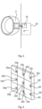
- Fig 3 is a schematic diagram illustrating the relationship between tag, user device and electronic lock in more detail.
- the tag 30 can be any of the tags 30a-c shown in Fig 1 .
- the tag 30 is located in direct vicinity of an associated electronic lock 22, to indicate to the user visually which lock the tag is associated with.
- the tag 30 can have a visual marking to make it easily distinguishable, which visual marking can also inform potential attackers that there is a strong security system protecting the vehicle.
- the tag 30 is not used directly to control access to the electronic lock. Instead, the tag 30 is used for the user to show intent. Since the active range of communication with the tag 30 is within centimetres, as long as the tags (by corresponding locks) are further away from each other than the communication range, intent is shown with great accuracy.
- Fig 4 there are a number of lockers with corresponding electronic locks 22a-i.
- Each electronic lock 22a-i has a corresponding tag 30a-i. Since the communication range is so short between the user device and the tags, the tags are also used here to shown intent with regard to which locker to open. These lockers can be placed within the vehicle to provide an extra layer of security for valuable goods. Still, the same mechanism is used here as for the doors of the vehicle, making the process simple and user friendly for the user.
- the goods can be secured by drawers with respective electronic locks and tags.
- the goods can be secured by bags with respective electronic locks and tags.
- intent can be optimised using tags while access control can be performed using communication between the lock and the user device.
- the communication between the lock and the user device can e.g. be performed using BLE or similar, and does not need to have the short communication range that is needed for the tags.
- DAD decentralised access delegation
- DAD solves a problem of access control without the need for a central access control system while still being able to implement flexible provision of access.
- DAD is something entirely different from these two solutions.
- DAD when a key (e.g. in the form of the user device) is presented for an electronic lock, the electronic lock checks that there is a valid delegation path from the electronic lock to the key.
- the delegation path contains a plurality of chain linked delegations which starts in the electronic lock and ends in the key.
- Each delegation is a delegation of an access right for the electronic lock from a delegator to a receiver.
- the delegation path can contain delegation(s) being locally stored by the electronic lock and delegation(s) communicated from the key.
- the delegation path can contain an arbitrary number of delegations. Some delegations can be authenticated using a digital signature and each delegation can be defined to have a specific validity time range.
- the electronic lock can perform access control without needing online access. Still, using the delegation path, great flexibility is achieved in how access rights are provided. Since no central point is needed, massive scalability is achieved. Moreover, there is no single point of failure or even a master key, which improves reliability and security.
- the vehicles can be owned by a first party, which delegates access to all electronic locks of the vehicles to a central delivery company, which delegates access to all electronic locks to a local delivery company.
- the local delivery company (using the access manager 7) can then delegate access on a per vehicle basis for each work shift with a corresponding validity time to conveniently provide access to a particular vehicle for the driver, but only when that driver is to use that particular vehicle. Also, the electronic locks do not need to have online access.
- the decentralised access control provided by DAD can not be achieved when RFID tags or NFC (Near Field Communication) tags are used also for access control.
- Fig 5 is a schematic diagram illustrating components of the user device 2 of Fig 1 .
- a processor 60 is provided using any combination of one or more of a suitable central processing unit (CPU), multiprocessor, microcontroller, digital signal processor (DSP), application specific integrated circuit etc., capable of executing software instructions 67 stored in a memory 64, which can thus be a computer program product.
- the processor 60 can be configured to execute the method described with reference to Fig 6 below.
- the memory 64 can be any combination of random access memory (RAM) and read only memory (ROM).
- the memory 64 also comprises persistent storage, which, for example, can be any single one or combination of magnetic memory, optical memory, solid-state memory or even remotely mounted memory.
- a data memory 66 is also provided for reading and/or storing data during execution of software instructions in the processor 60.
- the data memory 66 can be any combination of random access memory (RAM) and read only memory (ROM).
- the data memory 66 can comprise the lookup table defining a lock identifier for each tag identifier.
- the user device 2 further comprises an I/O interface 62 for communicating with other external entities.
- the I/O interface 62 also includes a user interface.
- a transceiver of the I/O interface 62 comprises suitable analogue and digital components to allow signal transmission and signal reception with a wireless device using one or more antennas.
- the transceiver can include a cellular module (using e.g. LTE (Long Term Evolution) or W-CDMA (wideband code division multiple access) for data access to the Internet.
- the transceiver comprises a short-range communication module, e.g. BLE or Bluetooth for communication with a smartphone, to thereby gain data access to the Internet.
- the transceiver also comprises circuitry to communicate with a tag, e.g. using NFC or RFID.
- the communication with the tag only works within a very short range, e.g. within 4 cm.
- a first biometric sensor 3a and a second biometric sensor 3b are shown. Additional biometric sensors can be added to increase reliability of biometric identification of a user.
- the user device 2 can be provided in two or more sections, in which case the different sections of the user device 2 can communicate with each other using a wireless link, e.g. BLE.
- a wireless link e.g. BLE.
- Fig 6 is a flow chart illustrating the method for requesting access to a physical space controlled by an electronic lock. The method is performed in the user device, e.g. a wearable device.
- a read tag step 40 the user device reads a tag using a near field radio protocol, yielding a tag identifier, the tag being distinct from the electronic lock.
- the near field radio protocol can have a range which is less than ten cm and can e.g. be RFID or NFC.
- a find associated lock id step 42 the user device finds, based on the tag identifier, a lock identifier associated with the tag identifier.
- the tag identifier is distinct from the lock identifier.
- the tags can be generic tags which are installed next to the locks. As long as the association between the tag identifier and the lock identifier is recorded, e.g. during installation, the tags can in this way be generic tags. This significantly simplifies production and installation, since there is no need to keep track of a specific pair of tag and lock during the production process and installation process.
- the step comprises using a lookup table to find the lock identifier associated with the tag identifier.
- the lookup table contains the tag identifiers of all tags in an access control system and their respective lock identifiers. Since the access control is performed independently between the user device and the electronic lock, the lookup table in itself does not pose a significant security risk.
- the lookup table can be stored in the user device. Alternatively or additionally, the lookup table is stored centrally and is consulted by the user device when needed.
- a send access request message step 44 the user device sends an access request message to the electronic lock having the lock identifier.
- Fig 7 shows one example of a computer program product comprising computer readable means.
- a computer program 91 can be stored, which computer program can cause a processor to execute methods described herein.
- the computer program product is an optical disc, such as a CD (compact disc) or a DVD (digital versatile disc) or a Blu-Ray disc.
- the computer program product could also be embodied in a memory of a device, such as the computer program product 64 of Fig 5 .
- the computer program 91 is here schematically shown as a track on the depicted optical disk, the computer program can be stored in any way which is suitable for the computer program product, such as a removable solid state memory, e.g. a Universal Serial Bus (USB) drive.
- USB Universal Serial Bus
Landscapes
- Engineering & Computer Science (AREA)
- Human Computer Interaction (AREA)
- Physics & Mathematics (AREA)
- General Physics & Mathematics (AREA)
- Computer Networks & Wireless Communication (AREA)
- Mechanical Engineering (AREA)
- Lock And Its Accessories (AREA)
Claims (12)
- Verfahren zum Anfordern von Zugang zu einem physikalischen Raum, der durch ein elektronisches Schloss kontrolliert wird, wobei der physikalische Raum einer einer Vielzahl von physikalischen Räumen ist, die jeweils durch ein elektronisches Schloss kontrolliert werden, wobei ein separates Etikett für jedes elektronische Schloss bereitgestellt und in der unmittelbaren Nähe davon angeordnet ist, wobei jedes Etikett von dem jeweiligen elektronischen Schloss verschieden ist, wobei jedes Etikett durch ein gleiches Nahfeldfunkprotokoll lesbar ist, um eine von einer Schlosskennung des jeweiligen elektronischen Schlosses verschiedene Etikettkennung hervorzubringen, wobei die Schlosskennung nicht von dem Etikett selbst lesbar ist und wobei die Etikette voneinander weiter als der Kommunikationsbereich des Nahfeldfunkprotokolls entfernt sind, wobei das Verfahren in einer Benutzervorrichtung (2) durchgeführt wird und die folgenden Schritte umfasst:- Lesen (40) eines der Etikette unter Verwendung des Nahfeldfunkprotokolls, wodurch eine Etikettkennung hervorgebracht wird;- Finden (42), basierend auf der hervorgebrachten Etikettkennung, einer mit der hervorgebrachten Etikettkennung assoziierten Schlosskennung und- Senden (44) einer Zugangsanforderungsnachricht an das elektronische Schloss, das die gefundene Schlosskennung aufweist,wobei der Schritt des Findens (42) einer Schlosskennung umfasst, eine Nachschlagetabelle zu verwenden oder zu konsultieren, um die mit der hervorgebrachten Etikettkennung assoziierte Schlosskennung zu finden.
- Verfahren nach Anspruch 1, wobei die Benutzervorrichtung (2) eine tragbare Vorrichtung ist.
- Verfahren nach einem der vorhergehenden Ansprüche, wobei die Vielzahl von physikalischen Räumen in einem Fahrzeug ist.
- Verfahren nach einem der vorhergehenden Ansprüche, wobei die Vielzahl von physikalische Räumen eine Vielzahl von Schränken, Schubladen oder Taschen ist.
- Zugangskontrollsystem, umfassend:- eine Vielzahl von elektronischen Schlössern (22a, 22b), jedes zum Kontrollieren des Zugangs zu einem jeweiligen physikalischen Raum einer Vielzahl von physikalischen Räumen, wobei jedes elektronische Schloss eine Schlosskennung aufweist;- eine Vielzahl von Etiketten (30a, 30b), wobei jedes Etikett unter Verwendung eines Nahfeldfunkprotokolls lesbar ist, um eine jeweilige Etikettkennung hervorzubringen, jedes Etikett von dem jeweiligen elektronische Schloss verschieden und in der unmittelbaren Nähe des jeweiligen elektronischen Schlosses angeordnet ist und von allen anderen Etiketten weiter als der Kommunikationsbereich des Nahfeldfunkprotokolls entfernt ist, jede Etikettkennung von der Schlosskennung des jeweiligen Schlosses verschieden ist und wobei jede Schlosskennung nicht von dem jeweiligen Etikett selbst lesbar ist;- eine Nachschlagetabelle, die eine Assoziation zwischen der Etikettkennung jedes Etiketts und der Schlosskennung des jeweiligen elektronischen Schlosses speichert, und- eine Benutzervorrichtung (2), umfassend:-- einen Prozessor (60), und-- einen Speicher (64), der Anweisungen (67) speichert, die, wenn sie durch den Prozessor ausgeführt werden, die Benutzervorrichtung veranlassen zum:--- Lesen eines Etiketts unter Verwendung des Nahfeldfunkprotokolls, wodurch eine Etikettkennung hervorgebracht wird;--- Verwenden oder Konsultieren der Nachschlagetabelle, um basierend auf der hervorgebrachten Etikettkennung eine mit der hervorgebrachten Etikettkennung assoziierte Schlosskennung zu finden, und--- Senden einer Zugangsanforderungsnachricht an das elektronische Schloss, das die gefundene Schlosskennung aufweist.
- Zugangskontrollsystem nach Anspruch 5, wobei die Benutzervorrichtung eine tragbare Vorrichtung ist.
- Zugangskontrollsystem nach Anspruch 5 oder 6, wobei die Nachschlagetabelle in der Benutzervorrichtung gespeichert ist.
- Fahrzeug, umfassend:- eine Vielzahl von physikalische Räumen und- das Zugangskontrollsystem nach einem der Ansprüche 5 bis 7, wobei jedes elektronische Schloss den Zugang zu einem jeweiligen einen der Vielzahl von physikalischen Räumen kontrolliert.
- Fahrzeug nach Anspruch 8, wobei die Vielzahl von physikalischen Räumen eine Ladefläche des Fahrzeugs und einen Fahrgastraum des Fahrzeugs umfasst.
- Fahrzeug nach Anspruch 8 oder 9, wobei die Vielzahl von physikalischen Räumen eine Vielzahl von Schränken umfasst.
- Fahrzeug nach einem der Ansprüche 8 bis 10, wobei die Vielzahl von physikalischen Räumen eine Vielzahl von Schubladen umfasst.
- Fahrzeug nach einem der Ansprüche 8 bis 10, wobei die Vielzahl von physikalischen Räumen eine Vielzahl von Taschen umfasst.
Applications Claiming Priority (2)
| Application Number | Priority Date | Filing Date | Title |
|---|---|---|---|
| EP17198088 | 2017-10-24 | ||
| PCT/EP2018/078974 WO2019081472A1 (en) | 2017-10-24 | 2018-10-23 | REQUEST FOR ACCESS TO A PHYSICAL SPACE CONTROLLED BY AN ELECTRONIC LOCK ASSOCIATED WITH A LABEL |
Publications (2)
| Publication Number | Publication Date |
|---|---|
| EP3701504A1 EP3701504A1 (de) | 2020-09-02 |
| EP3701504B1 true EP3701504B1 (de) | 2024-05-22 |
Family
ID=60190609
Family Applications (1)
| Application Number | Title | Priority Date | Filing Date |
|---|---|---|---|
| EP18786812.0A Active EP3701504B1 (de) | 2017-10-24 | 2018-10-23 | Zutrittsanfrage zu einem physikalischen raum, der von einem elektronischen schloss mit einem etikett kontrolliert wird |
Country Status (5)
| Country | Link |
|---|---|
| US (1) | US11501585B2 (de) |
| EP (1) | EP3701504B1 (de) |
| CN (1) | CN111279397A (de) |
| FI (1) | FI3701504T3 (de) |
| WO (1) | WO2019081472A1 (de) |
Families Citing this family (1)
| Publication number | Priority date | Publication date | Assignee | Title |
|---|---|---|---|---|
| US11639617B1 (en) | 2019-04-03 | 2023-05-02 | The Chamberlain Group Llc | Access control system and method |
Citations (1)
| Publication number | Priority date | Publication date | Assignee | Title |
|---|---|---|---|---|
| NL2015145B1 (nl) * | 2015-07-10 | 2017-02-01 | Boekit B V | Systeem voor het beheren van apparaten in een gebouw, apparaat en mobiel communicatiemiddel voor gebruik in een dergelijk systeem. |
Family Cites Families (19)
| Publication number | Priority date | Publication date | Assignee | Title |
|---|---|---|---|---|
| US20050184150A1 (en) | 2004-02-24 | 2005-08-25 | Welte Gregory A. | Device to prevent credit card loss |
| US20080204233A1 (en) * | 2007-02-27 | 2008-08-28 | Kavita Agrawal | System for tracking important travel items using rfid tags and pervasive computing devices |
| US8099380B1 (en) * | 2007-05-29 | 2012-01-17 | University Of Southern California | Blind evaluation of nearest neighbor queries wherein locations of users are transformed into a transformed space using a plurality of keys |
| US10121033B1 (en) * | 2011-11-30 | 2018-11-06 | Impinj, Inc. | Enhanced RFID tag authentication |
| US8469270B1 (en) * | 2012-02-25 | 2013-06-25 | Reagan Inventions, Llc | Systems and methods for indicating the existence of accessible information pertaining to articles of commerce |
| WO2013153481A1 (en) * | 2012-04-12 | 2013-10-17 | Koninklijke Philips N.V. | Identification sensor for gate identification of a person |
| US9659424B2 (en) * | 2013-06-20 | 2017-05-23 | Parakeet Technologies, Inc. | Technologies and methods for security access |
| CN103731485A (zh) * | 2013-12-26 | 2014-04-16 | 华为技术有限公司 | 一种网络设备、集群存储系统及分布式锁管理方法 |
| CN103971435B (zh) * | 2014-05-22 | 2016-07-06 | 广东欧珀移动通信有限公司 | 开锁方法、服务器、移动终端、电子锁及开锁系统 |
| US10096183B2 (en) * | 2014-06-02 | 2018-10-09 | Best Lockers, Llc | Mobile kiosk for intelligent securable devices system |
| EP3035299B1 (de) | 2014-12-18 | 2019-03-27 | Assa Abloy Ab | Authentifizierung eines Benutzers für Zugang zu einem physikalischen Raum |
| US11062542B2 (en) * | 2015-04-16 | 2021-07-13 | Assa Abloy Ab | Determining whether a user with a credential should be granted access to a physical space |
| US20180262891A1 (en) * | 2015-06-11 | 2018-09-13 | 3M Innovative Properties Company | Electronic access control systems and methods using near-field communications, mobile devices and cloud computing |
| US20170120864A1 (en) * | 2015-11-02 | 2017-05-04 | Myine Electronics, Inc. | Methods and Systems for Enabling a Vehicle Drive-Away |
| CN105488918A (zh) * | 2015-11-26 | 2016-04-13 | 国家电网公司 | 一种智能储物柜及其存取方法 |
| US9762581B1 (en) | 2016-04-15 | 2017-09-12 | Striiv, Inc. | Multifactor authentication through wearable electronic device |
| US10475115B2 (en) * | 2017-09-20 | 2019-11-12 | Bradford A. Minsley | System and method for managing distributed encrypted combination over-locks from a remote location |
| US10573171B2 (en) * | 2017-05-23 | 2020-02-25 | Lenovo (Singapore) Pte. Ltd. | Method of associating user input with a device |
| EP3783575B1 (de) * | 2017-06-02 | 2025-03-12 | Deutsche Post AG | Schliessfachsystemzugangskontrolle |
-
2018
- 2018-10-23 US US16/756,744 patent/US11501585B2/en active Active
- 2018-10-23 EP EP18786812.0A patent/EP3701504B1/de active Active
- 2018-10-23 WO PCT/EP2018/078974 patent/WO2019081472A1/en not_active Ceased
- 2018-10-23 CN CN201880068843.1A patent/CN111279397A/zh active Pending
- 2018-10-23 FI FIEP18786812.0T patent/FI3701504T3/fi active
Patent Citations (1)
| Publication number | Priority date | Publication date | Assignee | Title |
|---|---|---|---|---|
| NL2015145B1 (nl) * | 2015-07-10 | 2017-02-01 | Boekit B V | Systeem voor het beheren van apparaten in een gebouw, apparaat en mobiel communicatiemiddel voor gebruik in een dergelijk systeem. |
Also Published As
| Publication number | Publication date |
|---|---|
| US20210192877A1 (en) | 2021-06-24 |
| WO2019081472A1 (en) | 2019-05-02 |
| US11501585B2 (en) | 2022-11-15 |
| FI3701504T3 (fi) | 2024-06-20 |
| EP3701504A1 (de) | 2020-09-02 |
| CN111279397A (zh) | 2020-06-12 |
Similar Documents
| Publication | Publication Date | Title |
|---|---|---|
| US12052357B2 (en) | Smart lock unlocking method and related device | |
| US10937263B1 (en) | Smart credentials for protecting personal information | |
| US11887459B2 (en) | Wearable device with multibiometry | |
| EP3583006B1 (de) | Passives fahrzeugzugangssteuerungssystem mit bluetooth low energy (ble) zur verteidigung des systems gegen relaisattacken und verfahren dafür | |
| US20180268629A1 (en) | Intelligent Wireless Access System and Method for a Vehicle | |
| US10230706B2 (en) | Using personal RF signature for enhanced authentication metric | |
| US10332328B2 (en) | Device for protecting the access to a vehicle by means of a mobile phone | |
| US10752192B2 (en) | Intelligent event system and method for a vehicle | |
| US20140327517A1 (en) | Remote control system, and method for automatically locking and/or unlocking at least one movable panel of a motor vehicle and/or for starting a motor vehicle engine using a remote control system | |
| JP2020507700A (ja) | 多段階の車両進入許可 | |
| JP6531853B1 (ja) | 認証情報発行装置および配送システム | |
| CN106940922B (zh) | 用于针对交通工具检测所携带的物体的系统和方法 | |
| US9332112B2 (en) | Communications system and method in connection with vehicle | |
| EP3701504B1 (de) | Zutrittsanfrage zu einem physikalischen raum, der von einem elektronischen schloss mit einem etikett kontrolliert wird | |
| JP7095321B2 (ja) | サーバ装置および配送システム | |
| JP2016206707A (ja) | 生体情報認証システム | |
| US20200327471A1 (en) | Management device, management method, and management program | |
| EP3701506B1 (de) | Rolladen zum sichern eines physikalischen raumes in einem fahrzeug | |
| US12576808B2 (en) | Portable tools for use as vehicle security devices | |
| JP6447954B2 (ja) | スマートエントリーシステム | |
| WO2015041596A1 (en) | Method and system for wireless connection of at least one external device for communication with a vehicle | |
| KR100974929B1 (ko) | 도난 방지 시스템 및 방법 | |
| AU2023473598A1 (en) | Industrial equipment access control | |
| JP2017043203A (ja) | 車両制御システム |
Legal Events
| Date | Code | Title | Description |
|---|---|---|---|
| STAA | Information on the status of an ep patent application or granted ep patent |
Free format text: STATUS: UNKNOWN |
|
| STAA | Information on the status of an ep patent application or granted ep patent |
Free format text: STATUS: THE INTERNATIONAL PUBLICATION HAS BEEN MADE |
|
| PUAI | Public reference made under article 153(3) epc to a published international application that has entered the european phase |
Free format text: ORIGINAL CODE: 0009012 |
|
| STAA | Information on the status of an ep patent application or granted ep patent |
Free format text: STATUS: REQUEST FOR EXAMINATION WAS MADE |
|
| 17P | Request for examination filed |
Effective date: 20200421 |
|
| AK | Designated contracting states |
Kind code of ref document: A1 Designated state(s): AL AT BE BG CH CY CZ DE DK EE ES FI FR GB GR HR HU IE IS IT LI LT LU LV MC MK MT NL NO PL PT RO RS SE SI SK SM TR |
|
| AX | Request for extension of the european patent |
Extension state: BA ME |
|
| DAV | Request for validation of the european patent (deleted) | ||
| DAX | Request for extension of the european patent (deleted) | ||
| STAA | Information on the status of an ep patent application or granted ep patent |
Free format text: STATUS: EXAMINATION IS IN PROGRESS |
|
| 17Q | First examination report despatched |
Effective date: 20210521 |
|
| P01 | Opt-out of the competence of the unified patent court (upc) registered |
Effective date: 20230530 |
|
| GRAP | Despatch of communication of intention to grant a patent |
Free format text: ORIGINAL CODE: EPIDOSNIGR1 |
|
| STAA | Information on the status of an ep patent application or granted ep patent |
Free format text: STATUS: GRANT OF PATENT IS INTENDED |
|
| RIC1 | Information provided on ipc code assigned before grant |
Ipc: B60R 25/25 20130101ALI20240115BHEP Ipc: G07C 9/00 20200101AFI20240115BHEP |
|
| INTG | Intention to grant announced |
Effective date: 20240207 |
|
| GRAS | Grant fee paid |
Free format text: ORIGINAL CODE: EPIDOSNIGR3 |
|
| GRAA | (expected) grant |
Free format text: ORIGINAL CODE: 0009210 |
|
| STAA | Information on the status of an ep patent application or granted ep patent |
Free format text: STATUS: THE PATENT HAS BEEN GRANTED |
|
| AK | Designated contracting states |
Kind code of ref document: B1 Designated state(s): AL AT BE BG CH CY CZ DE DK EE ES FI FR GB GR HR HU IE IS IT LI LT LU LV MC MK MT NL NO PL PT RO RS SE SI SK SM TR |
|
| REG | Reference to a national code |
Ref country code: GB Ref legal event code: FG4D |
|
| REG | Reference to a national code |
Ref country code: CH Ref legal event code: EP |
|
| REG | Reference to a national code |
Ref country code: DE Ref legal event code: R096 Ref document number: 602018069812 Country of ref document: DE |
|
| REG | Reference to a national code |
Ref country code: IE Ref legal event code: FG4D |
|
| REG | Reference to a national code |
Ref country code: FI Ref legal event code: FGE |
|
| REG | Reference to a national code |
Ref country code: LT Ref legal event code: MG9D |
|
| REG | Reference to a national code |
Ref country code: NL Ref legal event code: MP Effective date: 20240522 |
|
| PG25 | Lapsed in a contracting state [announced via postgrant information from national office to epo] |
Ref country code: IS Free format text: LAPSE BECAUSE OF FAILURE TO SUBMIT A TRANSLATION OF THE DESCRIPTION OR TO PAY THE FEE WITHIN THE PRESCRIBED TIME-LIMIT Effective date: 20240922 |
|
| PG25 | Lapsed in a contracting state [announced via postgrant information from national office to epo] |
Ref country code: BG Free format text: LAPSE BECAUSE OF FAILURE TO SUBMIT A TRANSLATION OF THE DESCRIPTION OR TO PAY THE FEE WITHIN THE PRESCRIBED TIME-LIMIT Effective date: 20240522 |
|
| PG25 | Lapsed in a contracting state [announced via postgrant information from national office to epo] |
Ref country code: HR Free format text: LAPSE BECAUSE OF FAILURE TO SUBMIT A TRANSLATION OF THE DESCRIPTION OR TO PAY THE FEE WITHIN THE PRESCRIBED TIME-LIMIT Effective date: 20240522 |
|
| PG25 | Lapsed in a contracting state [announced via postgrant information from national office to epo] |
Ref country code: GR Free format text: LAPSE BECAUSE OF FAILURE TO SUBMIT A TRANSLATION OF THE DESCRIPTION OR TO PAY THE FEE WITHIN THE PRESCRIBED TIME-LIMIT Effective date: 20240823 |
|
| PG25 | Lapsed in a contracting state [announced via postgrant information from national office to epo] |
Ref country code: PT Free format text: LAPSE BECAUSE OF FAILURE TO SUBMIT A TRANSLATION OF THE DESCRIPTION OR TO PAY THE FEE WITHIN THE PRESCRIBED TIME-LIMIT Effective date: 20240923 |
|
| REG | Reference to a national code |
Ref country code: AT Ref legal event code: MK05 Ref document number: 1689398 Country of ref document: AT Kind code of ref document: T Effective date: 20240522 |
|
| PG25 | Lapsed in a contracting state [announced via postgrant information from national office to epo] |
Ref country code: NL Free format text: LAPSE BECAUSE OF FAILURE TO SUBMIT A TRANSLATION OF THE DESCRIPTION OR TO PAY THE FEE WITHIN THE PRESCRIBED TIME-LIMIT Effective date: 20240522 |
|
| PG25 | Lapsed in a contracting state [announced via postgrant information from national office to epo] |
Ref country code: ES Free format text: LAPSE BECAUSE OF FAILURE TO SUBMIT A TRANSLATION OF THE DESCRIPTION OR TO PAY THE FEE WITHIN THE PRESCRIBED TIME-LIMIT Effective date: 20240522 |
|
| PG25 | Lapsed in a contracting state [announced via postgrant information from national office to epo] |
Ref country code: AT Free format text: LAPSE BECAUSE OF FAILURE TO SUBMIT A TRANSLATION OF THE DESCRIPTION OR TO PAY THE FEE WITHIN THE PRESCRIBED TIME-LIMIT Effective date: 20240522 |
|
| PG25 | Lapsed in a contracting state [announced via postgrant information from national office to epo] |
Ref country code: PL Free format text: LAPSE BECAUSE OF FAILURE TO SUBMIT A TRANSLATION OF THE DESCRIPTION OR TO PAY THE FEE WITHIN THE PRESCRIBED TIME-LIMIT Effective date: 20240522 |
|
| PG25 | Lapsed in a contracting state [announced via postgrant information from national office to epo] |
Ref country code: LV Free format text: LAPSE BECAUSE OF FAILURE TO SUBMIT A TRANSLATION OF THE DESCRIPTION OR TO PAY THE FEE WITHIN THE PRESCRIBED TIME-LIMIT Effective date: 20240522 |
|
| PG25 | Lapsed in a contracting state [announced via postgrant information from national office to epo] |
Ref country code: PT Free format text: LAPSE BECAUSE OF FAILURE TO SUBMIT A TRANSLATION OF THE DESCRIPTION OR TO PAY THE FEE WITHIN THE PRESCRIBED TIME-LIMIT Effective date: 20240923 Ref country code: PL Free format text: LAPSE BECAUSE OF FAILURE TO SUBMIT A TRANSLATION OF THE DESCRIPTION OR TO PAY THE FEE WITHIN THE PRESCRIBED TIME-LIMIT Effective date: 20240522 Ref country code: NO Free format text: LAPSE BECAUSE OF FAILURE TO SUBMIT A TRANSLATION OF THE DESCRIPTION OR TO PAY THE FEE WITHIN THE PRESCRIBED TIME-LIMIT Effective date: 20240822 Ref country code: NL Free format text: LAPSE BECAUSE OF FAILURE TO SUBMIT A TRANSLATION OF THE DESCRIPTION OR TO PAY THE FEE WITHIN THE PRESCRIBED TIME-LIMIT Effective date: 20240522 Ref country code: LV Free format text: LAPSE BECAUSE OF FAILURE TO SUBMIT A TRANSLATION OF THE DESCRIPTION OR TO PAY THE FEE WITHIN THE PRESCRIBED TIME-LIMIT Effective date: 20240522 Ref country code: IS Free format text: LAPSE BECAUSE OF FAILURE TO SUBMIT A TRANSLATION OF THE DESCRIPTION OR TO PAY THE FEE WITHIN THE PRESCRIBED TIME-LIMIT Effective date: 20240922 Ref country code: HR Free format text: LAPSE BECAUSE OF FAILURE TO SUBMIT A TRANSLATION OF THE DESCRIPTION OR TO PAY THE FEE WITHIN THE PRESCRIBED TIME-LIMIT Effective date: 20240522 Ref country code: GR Free format text: LAPSE BECAUSE OF FAILURE TO SUBMIT A TRANSLATION OF THE DESCRIPTION OR TO PAY THE FEE WITHIN THE PRESCRIBED TIME-LIMIT Effective date: 20240823 Ref country code: ES Free format text: LAPSE BECAUSE OF FAILURE TO SUBMIT A TRANSLATION OF THE DESCRIPTION OR TO PAY THE FEE WITHIN THE PRESCRIBED TIME-LIMIT Effective date: 20240522 Ref country code: BG Free format text: LAPSE BECAUSE OF FAILURE TO SUBMIT A TRANSLATION OF THE DESCRIPTION OR TO PAY THE FEE WITHIN THE PRESCRIBED TIME-LIMIT Effective date: 20240522 Ref country code: AT Free format text: LAPSE BECAUSE OF FAILURE TO SUBMIT A TRANSLATION OF THE DESCRIPTION OR TO PAY THE FEE WITHIN THE PRESCRIBED TIME-LIMIT Effective date: 20240522 Ref country code: RS Free format text: LAPSE BECAUSE OF FAILURE TO SUBMIT A TRANSLATION OF THE DESCRIPTION OR TO PAY THE FEE WITHIN THE PRESCRIBED TIME-LIMIT Effective date: 20240822 |
|
| PG25 | Lapsed in a contracting state [announced via postgrant information from national office to epo] |
Ref country code: DK Free format text: LAPSE BECAUSE OF FAILURE TO SUBMIT A TRANSLATION OF THE DESCRIPTION OR TO PAY THE FEE WITHIN THE PRESCRIBED TIME-LIMIT Effective date: 20240522 |
|
| PG25 | Lapsed in a contracting state [announced via postgrant information from national office to epo] |
Ref country code: EE Free format text: LAPSE BECAUSE OF FAILURE TO SUBMIT A TRANSLATION OF THE DESCRIPTION OR TO PAY THE FEE WITHIN THE PRESCRIBED TIME-LIMIT Effective date: 20240522 |
|
| PG25 | Lapsed in a contracting state [announced via postgrant information from national office to epo] |
Ref country code: CZ Free format text: LAPSE BECAUSE OF FAILURE TO SUBMIT A TRANSLATION OF THE DESCRIPTION OR TO PAY THE FEE WITHIN THE PRESCRIBED TIME-LIMIT Effective date: 20240522 |
|
| PG25 | Lapsed in a contracting state [announced via postgrant information from national office to epo] |
Ref country code: RO Free format text: LAPSE BECAUSE OF FAILURE TO SUBMIT A TRANSLATION OF THE DESCRIPTION OR TO PAY THE FEE WITHIN THE PRESCRIBED TIME-LIMIT Effective date: 20240522 Ref country code: SK Free format text: LAPSE BECAUSE OF FAILURE TO SUBMIT A TRANSLATION OF THE DESCRIPTION OR TO PAY THE FEE WITHIN THE PRESCRIBED TIME-LIMIT Effective date: 20240522 |
|
| PG25 | Lapsed in a contracting state [announced via postgrant information from national office to epo] |
Ref country code: SM Free format text: LAPSE BECAUSE OF FAILURE TO SUBMIT A TRANSLATION OF THE DESCRIPTION OR TO PAY THE FEE WITHIN THE PRESCRIBED TIME-LIMIT Effective date: 20240522 |
|
| PG25 | Lapsed in a contracting state [announced via postgrant information from national office to epo] |
Ref country code: SM Free format text: LAPSE BECAUSE OF FAILURE TO SUBMIT A TRANSLATION OF THE DESCRIPTION OR TO PAY THE FEE WITHIN THE PRESCRIBED TIME-LIMIT Effective date: 20240522 Ref country code: SK Free format text: LAPSE BECAUSE OF FAILURE TO SUBMIT A TRANSLATION OF THE DESCRIPTION OR TO PAY THE FEE WITHIN THE PRESCRIBED TIME-LIMIT Effective date: 20240522 Ref country code: RO Free format text: LAPSE BECAUSE OF FAILURE TO SUBMIT A TRANSLATION OF THE DESCRIPTION OR TO PAY THE FEE WITHIN THE PRESCRIBED TIME-LIMIT Effective date: 20240522 Ref country code: EE Free format text: LAPSE BECAUSE OF FAILURE TO SUBMIT A TRANSLATION OF THE DESCRIPTION OR TO PAY THE FEE WITHIN THE PRESCRIBED TIME-LIMIT Effective date: 20240522 Ref country code: DK Free format text: LAPSE BECAUSE OF FAILURE TO SUBMIT A TRANSLATION OF THE DESCRIPTION OR TO PAY THE FEE WITHIN THE PRESCRIBED TIME-LIMIT Effective date: 20240522 Ref country code: CZ Free format text: LAPSE BECAUSE OF FAILURE TO SUBMIT A TRANSLATION OF THE DESCRIPTION OR TO PAY THE FEE WITHIN THE PRESCRIBED TIME-LIMIT Effective date: 20240522 |
|
| PG25 | Lapsed in a contracting state [announced via postgrant information from national office to epo] |
Ref country code: IT Free format text: LAPSE BECAUSE OF FAILURE TO SUBMIT A TRANSLATION OF THE DESCRIPTION OR TO PAY THE FEE WITHIN THE PRESCRIBED TIME-LIMIT Effective date: 20240522 |
|
| REG | Reference to a national code |
Ref country code: DE Ref legal event code: R097 Ref document number: 602018069812 Country of ref document: DE |
|
| PLBE | No opposition filed within time limit |
Free format text: ORIGINAL CODE: 0009261 |
|
| STAA | Information on the status of an ep patent application or granted ep patent |
Free format text: STATUS: NO OPPOSITION FILED WITHIN TIME LIMIT |
|
| PG25 | Lapsed in a contracting state [announced via postgrant information from national office to epo] |
Ref country code: SI Free format text: LAPSE BECAUSE OF FAILURE TO SUBMIT A TRANSLATION OF THE DESCRIPTION OR TO PAY THE FEE WITHIN THE PRESCRIBED TIME-LIMIT Effective date: 20240522 |
|
| 26N | No opposition filed |
Effective date: 20250225 |
|
| REG | Reference to a national code |
Ref country code: CH Ref legal event code: PL |
|
| PG25 | Lapsed in a contracting state [announced via postgrant information from national office to epo] |
Ref country code: MC Free format text: LAPSE BECAUSE OF FAILURE TO SUBMIT A TRANSLATION OF THE DESCRIPTION OR TO PAY THE FEE WITHIN THE PRESCRIBED TIME-LIMIT Effective date: 20240522 |
|
| PG25 | Lapsed in a contracting state [announced via postgrant information from national office to epo] |
Ref country code: LU Free format text: LAPSE BECAUSE OF NON-PAYMENT OF DUE FEES Effective date: 20241023 Ref country code: BE Free format text: LAPSE BECAUSE OF NON-PAYMENT OF DUE FEES Effective date: 20241031 |
|
| PG25 | Lapsed in a contracting state [announced via postgrant information from national office to epo] |
Ref country code: CH Free format text: LAPSE BECAUSE OF NON-PAYMENT OF DUE FEES Effective date: 20241031 |
|
| REG | Reference to a national code |
Ref country code: BE Ref legal event code: MM Effective date: 20241031 |
|
| PG25 | Lapsed in a contracting state [announced via postgrant information from national office to epo] |
Ref country code: SE Free format text: LAPSE BECAUSE OF FAILURE TO SUBMIT A TRANSLATION OF THE DESCRIPTION OR TO PAY THE FEE WITHIN THE PRESCRIBED TIME-LIMIT Effective date: 20240522 |
|
| PGFP | Annual fee paid to national office [announced via postgrant information from national office to epo] |
Ref country code: GB Payment date: 20250911 Year of fee payment: 8 |
|
| PGFP | Annual fee paid to national office [announced via postgrant information from national office to epo] |
Ref country code: FR Payment date: 20250908 Year of fee payment: 8 |
|
| PG25 | Lapsed in a contracting state [announced via postgrant information from national office to epo] |
Ref country code: IE Free format text: LAPSE BECAUSE OF NON-PAYMENT OF DUE FEES Effective date: 20241023 |
|
| PGFP | Annual fee paid to national office [announced via postgrant information from national office to epo] |
Ref country code: DE Payment date: 20250910 Year of fee payment: 8 |
|
| PGFP | Annual fee paid to national office [announced via postgrant information from national office to epo] |
Ref country code: FI Payment date: 20251014 Year of fee payment: 8 |
|
| PG25 | Lapsed in a contracting state [announced via postgrant information from national office to epo] |
Ref country code: CY Free format text: LAPSE BECAUSE OF FAILURE TO SUBMIT A TRANSLATION OF THE DESCRIPTION OR TO PAY THE FEE WITHIN THE PRESCRIBED TIME-LIMIT; INVALID AB INITIO Effective date: 20181023 |
|
| PG25 | Lapsed in a contracting state [announced via postgrant information from national office to epo] |
Ref country code: HU Free format text: LAPSE BECAUSE OF FAILURE TO SUBMIT A TRANSLATION OF THE DESCRIPTION OR TO PAY THE FEE WITHIN THE PRESCRIBED TIME-LIMIT; INVALID AB INITIO Effective date: 20181023 |