EP3701312B1 - Head-mounted augmented reality device employing an optical bench - Google Patents
Head-mounted augmented reality device employing an optical bench Download PDFInfo
- Publication number
- EP3701312B1 EP3701312B1 EP18867433.7A EP18867433A EP3701312B1 EP 3701312 B1 EP3701312 B1 EP 3701312B1 EP 18867433 A EP18867433 A EP 18867433A EP 3701312 B1 EP3701312 B1 EP 3701312B1
- Authority
- EP
- European Patent Office
- Prior art keywords
- optical
- optical bench
- alignment
- bench
- support structure
- Prior art date
- Legal status (The legal status is an assumption and is not a legal conclusion. Google has not performed a legal analysis and makes no representation as to the accuracy of the status listed.)
- Active
Links
Images





Classifications
-
- G—PHYSICS
- G02—OPTICS
- G02B—OPTICAL ELEMENTS, SYSTEMS OR APPARATUS
- G02B27/00—Optical systems or apparatus not provided for by any of the groups G02B1/00 - G02B26/00, G02B30/00
-
- G—PHYSICS
- G02—OPTICS
- G02B—OPTICAL ELEMENTS, SYSTEMS OR APPARATUS
- G02B27/00—Optical systems or apparatus not provided for by any of the groups G02B1/00 - G02B26/00, G02B30/00
- G02B27/01—Head-up displays
- G02B27/017—Head mounted
- G02B27/0176—Head mounted characterised by mechanical features
-
- G—PHYSICS
- G02—OPTICS
- G02B—OPTICAL ELEMENTS, SYSTEMS OR APPARATUS
- G02B27/00—Optical systems or apparatus not provided for by any of the groups G02B1/00 - G02B26/00, G02B30/00
- G02B27/01—Head-up displays
-
- G—PHYSICS
- G02—OPTICS
- G02B—OPTICAL ELEMENTS, SYSTEMS OR APPARATUS
- G02B27/00—Optical systems or apparatus not provided for by any of the groups G02B1/00 - G02B26/00, G02B30/00
- G02B27/01—Head-up displays
- G02B27/017—Head mounted
- G02B27/0172—Head mounted characterised by optical features
-
- G—PHYSICS
- G02—OPTICS
- G02B—OPTICAL ELEMENTS, SYSTEMS OR APPARATUS
- G02B27/00—Optical systems or apparatus not provided for by any of the groups G02B1/00 - G02B26/00, G02B30/00
- G02B27/01—Head-up displays
- G02B27/0179—Display position adjusting means not related to the information to be displayed
-
- G—PHYSICS
- G02—OPTICS
- G02B—OPTICAL ELEMENTS, SYSTEMS OR APPARATUS
- G02B27/00—Optical systems or apparatus not provided for by any of the groups G02B1/00 - G02B26/00, G02B30/00
- G02B27/10—Beam splitting or combining systems
-
- G—PHYSICS
- G02—OPTICS
- G02B—OPTICAL ELEMENTS, SYSTEMS OR APPARATUS
- G02B27/00—Optical systems or apparatus not provided for by any of the groups G02B1/00 - G02B26/00, G02B30/00
- G02B27/01—Head-up displays
- G02B27/0101—Head-up displays characterised by optical features
- G02B2027/0132—Head-up displays characterised by optical features comprising binocular systems
-
- G—PHYSICS
- G02—OPTICS
- G02B—OPTICAL ELEMENTS, SYSTEMS OR APPARATUS
- G02B27/00—Optical systems or apparatus not provided for by any of the groups G02B1/00 - G02B26/00, G02B30/00
- G02B27/01—Head-up displays
- G02B27/0101—Head-up displays characterised by optical features
- G02B2027/0138—Head-up displays characterised by optical features comprising image capture systems, e.g. camera
-
- G—PHYSICS
- G02—OPTICS
- G02B—OPTICAL ELEMENTS, SYSTEMS OR APPARATUS
- G02B27/00—Optical systems or apparatus not provided for by any of the groups G02B1/00 - G02B26/00, G02B30/00
- G02B27/01—Head-up displays
- G02B27/0149—Head-up displays characterised by mechanical features
- G02B2027/0161—Head-up displays characterised by mechanical features characterised by the relative positioning of the constitutive elements
- G02B2027/0163—Electric or electronic control thereof
-
- G—PHYSICS
- G02—OPTICS
- G02B—OPTICAL ELEMENTS, SYSTEMS OR APPARATUS
- G02B27/00—Optical systems or apparatus not provided for by any of the groups G02B1/00 - G02B26/00, G02B30/00
- G02B27/01—Head-up displays
- G02B27/017—Head mounted
- G02B2027/0178—Eyeglass type
-
- G—PHYSICS
- G02—OPTICS
- G02B—OPTICAL ELEMENTS, SYSTEMS OR APPARATUS
- G02B27/00—Optical systems or apparatus not provided for by any of the groups G02B1/00 - G02B26/00, G02B30/00
- G02B27/01—Head-up displays
- G02B27/0179—Display position adjusting means not related to the information to be displayed
- G02B2027/0181—Adaptation to the pilot/driver
Definitions
- the present invention relates to augmented reality displays and, in particular, provides a head-mounted augmented reality device employing an optical bench to achieve and preserve alignment of the optical modules.
- Such optical modules typically include a collimating display source, which may be either an active illumination display or a light source illuminating a light-modulating display combined with collimating optics, and a light guide which receives a collimated image from the collimating display source and projects it into the eye of an observer.
- a collimating display source which may be either an active illumination display or a light source illuminating a light-modulating display combined with collimating optics
- a light guide which receives a collimated image from the collimating display source and projects it into the eye of an observer.
- a head-mounted augmented reality device for displaying an augmented reality display to a user viewing a real scene as specified in appended claim 1.
- the optical bench is further provided with a bolt hole for receiving a bolt for tightening each of the optical modules against each corresponding planar alignment surface.
- the at least one planar alignment surface for aligning the right optical module and the at least one planar alignment surface for aligning the left optical module are inclined relative to each other to define an angle of binocular convergence.
- each of the first and second sets of alignment features comprises two planar alignment surfaces disposed bilaterally relative to the coupling-out region of a corresponding one of the optical modules.
- the optical bench is formed as a unitary block of material.
- the optical bench comprises a first closed-loop frame for rigidly supporting the right optical module and a second closed-loop frame for rigidly supporting the left optical module.
- the optical bench further comprises camera alignment features for aligning at least one imaging device relative to the pair of optical modules.
- the suspension arrangement comprises at least one elastomeric damping element deployed to inhibit passing of vibrations from the support structure to the optical bench.
- the optical bench and the pair of optical modules together have an overall width, and wherein the suspension arrangement connects to the optical bench only within a central region of the width.
- the support structure comprises a casing at least partially enclosing the optical bench, wherein the casing is spaced from the optical bench and from the pair of optical modules so as to avoid contact between the casing and both the optical bench and the pair of optical modules under a range of normal operating conditions.
- At least part of the waveguides project downwards from the casing.
- the support structure comprises a headband for encircling the head of the user.
- the support structure has a pair of side arms deployed for engaging ears of the user.
- the present invention is a head-mounted augmented reality device.
- FIGS. 1-14C illustrate various embodiments and various components of a head-mounted augmented reality device, generally designated 10, for displaying an augmented reality display to a user viewing a real scene.
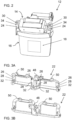
- device 10 includes a pair of optical modules 12, such as is illustrated in FIG. 1 , including a right optical module for a right eye of the user and a left optical module for a left eye of the user.
- each optical module 12 includes a collimating display source 14 optically coupled to a light guide 16, which is at least partially transparent and is configured to guide image illumination projected by collimating display source 12 to a coupling-out region 18 where it couples out at least some of the image illumination from the coupling-out region towards an eye of the user.
- the device also includes a support structure 20 configured to engage regions of a head of the user so as to be supported by the head of the user.
- device 10 includes an optical bench 22 which provides a first set of alignment features for aligning and affixing the right optical module, a second set of alignment features for aligning and affixing the left optical module, and a suspension arrangement for suspending the optical bench relative to the support structure.
- optical bench 22 provides the sole mechanical connection between the pair of optical modules 12 and support structure 20.
- the optical bench preferably provides a relatively rigid interconnection between the optical modules, defining and maintaining accurate alignment between the two optical modules while at least partially isolating the optical modules from much of the stress, vibration and/or impact to which the body-mounted support structure may be exposed during normal use.
- the optical bench may also serve to define and maintain alignment between the optical modules and additional components, such as camera(s) and/or an inertial measurement unit (IMU), and similarly protect those elements from at least part of the mechanical and/or thermally-induced stresses to which the device may be exposed.
- additional components such as camera(s) and/or an inertial measurement unit (IMU)
- the optical modules 12 referred to herein may be any type of optical module which includes a collimated image projector, referred to herein as collimating display source 14, and an at least partially transparent combiner, referred to herein as light guide 16, for combining the projected image illumination with light from the real world to provide an augmented reality display.
- the collimating display source is typically based on an image generating element such as an OLED array or an illuminated LCOS array, combined with collimating optics, typically in a compact configuration based on polarized beam splitters (PBS).
- PBS polarized beam splitters
- the optical modules provide a mechanism for optical aperture expansion to enable use of a miniature image projector while achieving a relatively larger angular field of view and "eyebox" of available eye motion over which the displayed image can be seen.
- optical aperture expansion includes, as one particularly preferred but non-limiting example, the use of obliquely angled partially reflective surfaces within light guide 16, optionally in a two-stage expansion arrangement to achieve two dimensional aperture expansion, such as the various optical modules commercially available from Lumus Ltd. (Israel).
- Another aperture expansion technology commercially available from various sources employs diffractive optical elements to achieve coupling out of the image illumination from the light guide over an expanded area. It should be noted that the above are only examples, and that the present invention is applicable to any available technology which includes a display source and combiner to provide an augmented reality display. Details of the optical module design do not per se constitute part of the invention, and will therefore not be further discussed in this document.
- Optical modules 12 for implementing the present invention may come in a number of different configurations and form-factors.
- FIGS. 1-13C herein illustrate configurations suitable for a "top-down" implementation, where the image illumination is directed into the light guide from the top edge of the light guide. It should be noted, however, that the invention is equally applicable to implementations in which the image illumination is introduced from a side, or from a corner, of the light guide. One such implementation will be discussed below with reference to FIGS. 14A-14C .
- mounting of the optical module 12 is achieved via two mounting regions 24 which are located on opposite sides of the collimating display source 14, and are thus disposed bilaterally relative to the coupling-out region 18 of the optical module. Spacing apart of the mounting regions in this manner tends to increase the precision of the alignment of the components.
- Each mounting region 24 defines a reference location formed with complementary features for alignment with a corresponding set of alignment features on optical bench 22.
- each set of alignment features of optical bench 22 includes at least one, and in this case two, planar alignment surfaces 26 and at least two locating features for locating known reference locations of optical module 12 relative to planar alignment surfaces 26.
- the at least two locating features are illustrated here as an alignment aperture 28 for receiving an alignment pin 30 which projects from a planar alignment surface of mounting region 24 of the optical module.
- an equivalent effect could be achieved by providing an alignment pin projecting from alignment surface 26 and an alignment aperture in the planar surface of region 24, or two alignment apertures with a separate pin which engages both.
- Optical bench 22 is also provided with a bolt hole 32, typically also in the area of alignment surface 26, for receiving a bolt for tightening each of the optical modules against each corresponding planar alignment surface.
- Optical module 12 preferably has corresponding threaded bolt holes 34 so that, when the mounting regions 24 of optical module 12 are brought together with planar alignment surfaces 26 of optical bench 22, with alignment pins 30 engaged in alignment apertures 28, a pair of bolts 36 can be used to tighten the elements together, as illustrated in FIGS. 4 , 5 and 7B .
- each optical module 12 to optical bench 22 with accurately defined orientation in 6 degrees of freedom (three linear/translational and three angular/rotational).
- tightening of planar surface against a planar surface is sufficient to define two rotational orientations and one translational degree of freedom (perpendicular to the plane).
- Engagement of a first alignment pin with an alignment aperture then excludes two in-plane translational degrees of freedom, leaving only uncertainty regarding rotation about the pin as an axis.
- Engagement of a second alignment pin with an alignment aperture, spaced from the first engagement thus fully defines the alignment in all 6 degrees of freedom.
- the second alignment aperture may advantageously be implemented as an oval aperture or slot elongated in a direction towards/away from the first alignment aperture, which is still sufficient to fully determine the in-plane rotational orientation of the overall engagement.
- Surfaces 24 and 26 are preferably accurate interface surfaces, which may be specially processed during manufacture to achieve an enhanced level of precision compared to other regions of these elements, for example, by employing a machining or grinding process to achieve high precision planar surfaces. By providing planar surfaces in two spaced-apart locations for each optical module, highly precise alignment precision can be achieved. It should be noted that the particular implementation of alignment features described here is merely exemplary, and that various configurations of alignment features may equally be used. Other examples include various combinations of alignment surfaces with ridges, slots or edge abutment features which align the optical modules by abutment with corresponding features on the optical module mounting regions 24.
- the two planar alignment surfaces 26 for aligning each optical module 12 are preferably coplanar.
- the surfaces for aligning one optical module may also be coplanar with the surfaces for aligning the other optical module, in which case the optical axes of the two displays may either be parallel or a slight convergence may be introduced either digitally or in the alignment of the optical components.
- the alignment surfaces 26 for aligning the right optical module 12 are inclined relative to the alignment surfaces for aligning the left optical module to define an angle of binocular convergence.
- the alignment surfaces for each optical module are inclined by 0.45 degrees to a reference plane to give an angle of 179.1 degrees between the alignment surfaces, corresponding to binocular convergence at about 4 meters from the user.
- the extent of binocular convergence desired may vary according to the intended application, typically corresponding to the real-world working range onto which the augmented reality display is to be superimposed.
- outdoor applications may employ a more distant point of convergence, typically in the 6-10 meter range
- AR-assisted surgical applications may employ a shorter convergence geometry, typically in the 0.4-1 meter range.
- the convergence distance is also a function of the inter-pupillary distance (IPD), as defined by simple trigonometry, with the ratio of half of the IPD to the convergence length equal to the tangent of the inclination angle of each optical module to the reference plane.
- IPD inter-pupillary distance
- an average value for IPD gives sufficient accuracy.
- optical bench 22 may advantageously be formed as a unitary block of material, which tends to enhance its rigidity and structural strength for a given weight.
- Suitable materials for optical bench 22 include, but are not limited to, various metals or metal alloys, such as aluminum, and fiber-reinforced polymers such as carbon composite materials.
- the design and dimensions of the optical bench, as well as the relevant manufacturing processes, will be adjusted according to the properties of the chosen material, as will be clear to a person having ordinary skill in the art.
- substantially rigid is used to refer to a structure which maintains alignment of the optical modules over a range of mechanical operating conditions to which a body-mounted device is normally exposed, which includes the linear and angular accelerations performed by the human head and/or body during movement, and bearing in mind the weight of the modules themselves.
- optical bench 22 may also be required to support a number of different components for which accurate alignment with the optical modules is critical and/or for which close proximity to the optical modules is advantageous. In the example of FIGS.
- this includes a camera assembly 40 including a stereo pair of cameras 42, an IMU 44, and driver circuitry 46 for the optical modules 12.
- Each of these elements is typically provided with a dedicated attachment configuration in the structure of optical bench, such as a front bracket 48 providing camera alignment features for mounting camera assembly 40 (which is here integrated with the IMU 44) and top brackets 50 for attachment of driver circuitry 46.
- a front bracket 48 providing camera alignment features for mounting camera assembly 40 (which is here integrated with the IMU 44) and top brackets 50 for attachment of driver circuitry 46.
- the positioning and weight of these components impose further mechanical requirements on the design of optical bench 22.
- optical bench 22 employs at least one closed-loop structure, and most preferably a first closed-loop frame for rigidly supporting the right optical module and a second closed-loop frame for rigidly supporting the left optical module, as seen in FIGS. 3A-5 .
- certain implementations of the present invention achieve enhanced multi-axis stiffness by using cross-beams with asymmetric stiffness, where the directions of maximal stiffness are non-parallel.
- This option is best illustrated in FIG. 6 , where the vertical cross-sectional view cuts through the two cross-beams of one of the closed loops (the shaded areas).
- Each cross-beam has a cross-section which has a long axis and a short axis, in this case, the long side and the short side of a rectangular cross-section.
- the long axis of the lower cross-beam is significantly non-parallel (more than 45°), and preferably roughly perpendicular (90° ⁇ 15°) to the long axis of the upper cross-beam cross-section, thereby providing enhanced resistance to bending moments in different directions.
- FIGS. 13A-13C illustrate a reduced version of optical bench 22 used to support a pair of optical modules 12 according to an alternative implementation of the present invention.
- the details of the optical bench design may be varied for each particular application according to the specific combination of components to be supported and the available space according to the desired form factor of the final device.
- the attachment position of optical modules 12 to optical bench 22 is adjustable to accommodate different interpupillary distances (IPD).
- IPD interpupillary distances
- the AR displays of the present invention are typically insensitive to variations in IPD, so long as the eye motion box of the user does not take the field of view of the user outside the coupling-out region 18 from which the display image illumination is projected.
- adjustability of the IPD may allow the use of a relatively smaller coupling-out region, and consequently a reduced overall size of the projection system.
- FIG. 7A One particularly preferred option for adjusting IPD is illustrated in FIG. 7A , where alignment aperture 28 and bolt hole 32 are formed as slots elongated in the horizontal direction. This relaxes one degree of freedom for horizontal translation of the optical module over a predefined range of motion.
- the image projection of optical module 12 is generally insensitive to in-plane translation without rotation, so long as the limits of the display area are not reached, so this adjustment does not impact the display.
- a range of a few millimeters in either direction for each of the two eyes is typically enough to adjust an IPD between the (centers of) the coupling out regions 18, to accommodate IPD variations for a majority of the population, and allows a corresponding reduction in the size of the coupling-out region 18.
- each optical module may be fixed, as before, by tightening of bolts 36 which clamp the modules in place by frictional contact.
- spring washers or some other resilient element, may be provided to provide frictional retention of the position of each optical module, but allowing lateral displacement of the optical module by the user simply by applying gentle manual force to overcome the frictional retention.
- the alignment features of the optical bench reliably maintain the desired alignment of the optical modules in angular orientation about all axes and in two linear dimensions, thereby accommodating convenient IPD adjustment without requiring complex displacement mechanisms. As illustrated in FIG. 8 , any parts of support structure 20 that are adjacent to any part of the optical modules are implemented with sufficient clearance to accommodate the available range of adjustment for the optical module position.
- the suspension arrangement connects to the optical bench only within a central region of the width, defined as within a central 20 percent, of the overall width of the assembly of optical bench 22 with optical modules 12. Most preferably, the connection is limited to within the central 10 percent of the overall width, which can be achieved, for example, by attaching optical bench 22 to the support structure only via a central attachment surface 52 ( FIG. 12A ). Attachment may be rigid, but is more preferably via at least one elastomeric damping element deployed to inhibit (attenuate) transmission of vibrations from the support structure to optical bench 22. By supporting optical bench 22 only in a central region, transfer of stress from the support structure to the optical bench is substantially eliminated, allowing the support structure to bend, twist and/or undergo thermal expansion or contraction without introducing corresponding deformations or stresses to the optical assembly.
- a more sophisticated suspension arrangement may be provided which maintains alignment of optical bench 22 relative to support structure 20 while more effectively attenuating vibrations between the elements.
- An example of such a suspension arrangement is illustrated with reference to FIGS. 9A-11B .
- the support structure (not shown) is here provided with two side brackets 54 terminating at apertures 56 within which elastomeric grommets 58 are positioned.
- a bolt 60 and washer 62 pass through a central bore of each grommet 58 and engage a threaded aperture 64 on each side of optical bench 22.
- the assembled connection is illustrated in cross-section in FIG. 9B .
- This bilateral attachment to side brackets 54 suspends optical bench 22 in a well-defined position relative to five out of the six degrees of freedom illustrated in FIG. 11A , namely, three axes of linear displacement and two axes of rotation. This leaves only the rotation axis labeled "6" in FIG.
- FIG. 11A corresponding to rotation about the common axis of bolts 60.
- This last degree of rotational freedom is cancelled by a damping connector 66 which is attached off-axis relative to bolts 60 near the center of the optical bench, and is connected via another bracket (not shown) to the support structure, thereby forming a damped connection between optical bench 22 and the support structure.
- This geometry is best seen in FIG. 11B .
- threaded apertures 56 are located so that the assembly of optical bench 22 with the other components that are mounted thereon has a center of mass that lies substantially on an axis between threaded apertures 56. This ensures that any impact or vibration transferred to the assembly via this support structure does not give rise to a net moment, which could lead to further oscillatory motion.
- each interconnection occurs through an elastomeric damping element which has the ability to attenuate impacts and vibrations, and to deform under conditions of stress (such as through differentials in thermal expansion coefficients) so as to avoid conveying significant stress to the optical bench.
- the elastomeric elements also contribute to thermal isolation of the optical bench and associated optical components.
- support structure 20 includes a casing 68 at least partially enclosing optical bench 22, as best seen in FIG. 10 .
- casing 68 is preferably spaced from optical bench 22 and from optical modules 12 by a minimum gap 70 so as to avoid contact between the casing and both the optical bench and the pair of optical modules under a range of normal operating conditions.
- the "range of normal operating conditions” in this context relates to conditions of vibration, mechanical stress, and operating temperature range over which the product is typically required to operate, as defined by various standards and as known in the art.
- the gap should be sufficient that, if the device is dropped from a height of up to at least 1 meter onto a hard surface, the gap is not closed, and the impulse of the impact is conveyed to the optical bench only through the elastomeric damping elements.
- the option of a casing which at least partially encloses the optical bench and various electronic and/or optical components of the device may advantageously be implemented in a "top-down" design, where the image illumination is introduced at the top of the light guide 16 and propagates downwards within the light guide.
- at least part of the waveguides 16 of optical modules 12 preferably project downwards from casing 68, as seen in FIGS. 1 and 8 .
- optical bench 22 preferably provides the sole mechanical connection between the pair of optical modules 12 and support structure 20.
- mechanical connection is used to refer to any connection between two elements which is intended to bear load and convey forces between the elements.
- flexible electrical cables which pass between the support structure and the optical modules, providing power and video signals etc. Although these flexible cables may convey some small force between the elements, any such forces are unintended, intentionally minimized, and are negligible compared to the mechanical connections which support the structures.
- the term “sole mechanical connection” does not exclude such interconnections that are not intended to be load bearing.
- FIGS. 14A-14C although the invention has been illustrated thus far with reference to a top-down optical module implementation, it can equally be implemented using other configurations which, in some cases, may provide additional advantages.
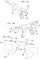
- FIGS. 14A and 14B illustrate an optical bench 22 not according to the claimed invention implemented as a central block for linking between two light guides 16, as seen in FIG. 14C , for a side-injected image implementation, where the collimating display source (not shown) is located at the lateral edge of each light guide.
- This implementation also illustrates an alternative implementation not according to the claimed invention of the alignment features for aligning and affixing each optical module.
Landscapes
- Physics & Mathematics (AREA)
- General Physics & Mathematics (AREA)
- Optics & Photonics (AREA)
- Mounting And Adjusting Of Optical Elements (AREA)
Description
- The present invention relates to augmented reality displays and, in particular, provides a head-mounted augmented reality device employing an optical bench to achieve and preserve alignment of the optical modules.
- Augmented reality, also referred to as mixed reality, is a technology that allows virtual imagery to be mixed with a user's view of the real world. In addition to making the physical properties (e.g. shape, color, size, texture) of virtual objects realistic in a display, it is desired that their position and movement with respect to real objects display realistically. In order to enable such functionality in a head mounted device, additional sensors such as cameras and orientation sensors may be mounted alongside compact optical modules which integrate the real and virtual imagery. Such compact optical elements serve as both an imaging lens and a combiner, in which a two-dimensional display is imaged to infinity and reflected into the eye of an observer. Such optical modules typically include a collimating display source, which may be either an active illumination display or a light source illuminating a light-modulating display combined with collimating optics, and a light guide which receives a collimated image from the collimating display source and projects it into the eye of an observer.
- The mechanical alignment and placement stability requirements between the collimating display source components and the light guide are stringent. Furthermore, the alignment and placement of the optical modules with respect to each other for binocular vision, as well as alignment with respect to any additional sensors and with respect to the observer, are subject to tight tolerances. Mechanical stress on the device, vibrations, shock, thermal fluctuations and thermal gradients may all lead to abrupt or gradual misalignment of the optical modules and other components, or damage to the modules. The US patent publication
US-A-2009180194 discloses a head-mounted augmented reality device using an optical bench holding the two optical modules comprising the displays for binocular vision. - The present invention is a head-mounted augmented reality device according to the appended claims.
- According to the teachings of an embodiment of the present invention there is provided, a head-mounted augmented reality device for displaying an augmented reality display to a user viewing a real scene as specified in appended
claim 1. - According to a further feature of an embodiment of the present invention, the optical bench is further provided with a bolt hole for receiving a bolt for tightening each of the optical modules against each corresponding planar alignment surface.
- According to a further feature of an embodiment of the present invention, the at least one planar alignment surface for aligning the right optical module and the at least one planar alignment surface for aligning the left optical module are inclined relative to each other to define an angle of binocular convergence.
- According to a further feature of an embodiment of the present invention, each of the first and second sets of alignment features comprises two planar alignment surfaces disposed bilaterally relative to the coupling-out region of a corresponding one of the optical modules.
- According to a further feature of an embodiment of the present invention, the optical bench is formed as a unitary block of material.
- According to a further feature of an embodiment of the present invention, the optical bench comprises a first closed-loop frame for rigidly supporting the right optical module and a second closed-loop frame for rigidly supporting the left optical module.
- According to a further feature of an embodiment of the present invention, the optical bench further comprises camera alignment features for aligning at least one imaging device relative to the pair of optical modules.
- According to a further feature of an embodiment of the present invention, the suspension arrangement comprises at least one elastomeric damping element deployed to inhibit passing of vibrations from the support structure to the optical bench.
- According to a further feature of an embodiment of the present invention, the optical bench and the pair of optical modules together have an overall width, and wherein the suspension arrangement connects to the optical bench only within a central region of the width.
- According to a further feature of an embodiment of the present invention, the support structure comprises a casing at least partially enclosing the optical bench, wherein the casing is spaced from the optical bench and from the pair of optical modules so as to avoid contact between the casing and both the optical bench and the pair of optical modules under a range of normal operating conditions.
- According to a further feature of an embodiment of the present invention, at least part of the waveguides project downwards from the casing.
- According to a further feature of an embodiment of the present invention, the support structure comprises a headband for encircling the head of the user.
- According to a further feature of an embodiment of the present invention, the support structure has a pair of side arms deployed for engaging ears of the user.
- The invention is herein described, by way of example only, with reference to the accompanying drawings, wherein:
-
FIG. 1 is an isometric view of a head-mounted augmented reality device, constructed and operative according to an embodiment of the present invention; -
FIG. 2 is an isometric view of an optical module for use in the device ofFIG. 1 ; -
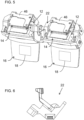
FIGS. 3A and 3B are back and front isometric views, respectively, of an optical bench for use in the device ofFIG. 1 ; -
FIGS. 4A and 4B are partial isometric views illustrating part of the optical bench ofFIG. 3A before and during, respectively, assembly of the optical module ofFIG. 2 to the optical bench; -
FIG. 4C is a front view of the assembly of the optical bench with two optical modules; -
FIG. 5 is an isometric view of the assembly ofFIG. 4C after attachment of additional driver circuitry to the assembly; -
FIG. 6 is a cross-sectional view taken through the optical bench ofFIG. 3A along a vertical plane through the center of a closed loop of the optical bench; -
FIGS. 7A and 7B are views similar toFIGS. 4A and 4B illustrating a variant implementation allowing interpupillary distance adjustment between the optical modules according to the claimed invention; -
FIG. 8 is a partial isometric view from beneath the device ofFIG. 1 illustrating a spacing around the optical modules to accommodate adjustment of interpupillary distance; -
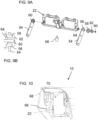
FIG. 9A is an exploded isometric view illustrating a suspension arrangement for suspending the optical bench ofFIG. 3A from a support structure, the suspension arrangement including a rotatable damping engagement; -
FIG. 9B is a cross-sectional view taken through the rotatable damping engagement along a plane parallel to the axis of rotation; -
FIG. 10 is a partial vertical cross-sectional view taken along a mid-plane of the device ofFIG. 1 illustrating mounting of the optical bench via a suspension arrangement within a casing; -
FIG. 11A is a schematic isometric illustration of the optical bench assembly mounted via the suspension arrangement showing the various directions of linear and rotational motion for which the suspension arrangement provides location and damping; -
FIG. 11B is a schematic side view illustrating the relative positioning of the various damping elements of the suspension arrangement; -
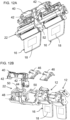
FIGS. 12A and 12B are an assembled and an exploded isometric view, respectively, of an assembly of the optical modules and optical bench ofFIG. 4C together with additional components that are mounted on the optical bench; -
FIGS. 13A and 13B are front and back isometric views, respectively, of an alternative implementation of an optical bench for use in an alternative implementation of the present invention; -
FIG. 13C is an isometric view of an assembly of the optical bench ofFIG. 13A with the optical modules ofFIG. 2 ; -
FIGS. 14A and 14B are two rear isometric views of an alternative implementation of an optical bench not according to the claimed invention; and -
FIG. 14C is a partial isometric view of an assembly of the optical bench ofFIG. 14A with two optical modules to form an alternative implementation not according to the claimed invention. - The present invention is a head-mounted augmented reality device.
- The principles and operation of devices according to the present invention may be better understood with reference to the drawings and the accompanying description.
- Referring now to the drawings,
FIGS. 1-14C illustrate various embodiments and various components of a head-mounted augmented reality device, generally designated 10, for displaying an augmented reality display to a user viewing a real scene. In general terms,device 10 includes a pair ofoptical modules 12, such as is illustrated inFIG. 1 , including a right optical module for a right eye of the user and a left optical module for a left eye of the user. As best seen inFIG. 2 , eachoptical module 12 includes acollimating display source 14 optically coupled to alight guide 16, which is at least partially transparent and is configured to guide image illumination projected by collimatingdisplay source 12 to a coupling-outregion 18 where it couples out at least some of the image illumination from the coupling-out region towards an eye of the user. - The device also includes a
support structure 20 configured to engage regions of a head of the user so as to be supported by the head of the user. It is a particular feature of one aspect of the present invention thatdevice 10 includes anoptical bench 22 which provides a first set of alignment features for aligning and affixing the right optical module, a second set of alignment features for aligning and affixing the left optical module, and a suspension arrangement for suspending the optical bench relative to the support structure. It is a particularly preferred feature of this aspect of the present invention thatoptical bench 22 provides the sole mechanical connection between the pair ofoptical modules 12 andsupport structure 20. - Use of an optical bench in this manner provides a number of advantages over direct mounting of the optical modules to the body-mounted support structure. Specifically, the optical bench preferably provides a relatively rigid interconnection between the optical modules, defining and maintaining accurate alignment between the two optical modules while at least partially isolating the optical modules from much of the stress, vibration and/or impact to which the body-mounted support structure may be exposed during normal use. The optical bench may also serve to define and maintain alignment between the optical modules and additional components, such as camera(s) and/or an inertial measurement unit (IMU), and similarly protect those elements from at least part of the mechanical and/or thermally-induced stresses to which the device may be exposed. The use of a dedicated optical bench, typically implemented using more rigid and/or more precisely machinable material than is used for the support structure, facilitates more precise alignment of the optical modules than could otherwise be achieved. These and other advantages of the various embodiments of the present invention will be better understood with reference to the further description below.
- The
optical modules 12 referred to herein may be any type of optical module which includes a collimated image projector, referred to herein as collimatingdisplay source 14, and an at least partially transparent combiner, referred to herein aslight guide 16, for combining the projected image illumination with light from the real world to provide an augmented reality display. The collimating display source is typically based on an image generating element such as an OLED array or an illuminated LCOS array, combined with collimating optics, typically in a compact configuration based on polarized beam splitters (PBS). Most preferably, the optical modules provide a mechanism for optical aperture expansion to enable use of a miniature image projector while achieving a relatively larger angular field of view and "eyebox" of available eye motion over which the displayed image can be seen. Available technologies for achieving such optical aperture expansion include, as one particularly preferred but non-limiting example, the use of obliquely angled partially reflective surfaces withinlight guide 16, optionally in a two-stage expansion arrangement to achieve two dimensional aperture expansion, such as the various optical modules commercially available from Lumus Ltd. (Israel). Another aperture expansion technology commercially available from various sources employs diffractive optical elements to achieve coupling out of the image illumination from the light guide over an expanded area. It should be noted that the above are only examples, and that the present invention is applicable to any available technology which includes a display source and combiner to provide an augmented reality display. Details of the optical module design do not per se constitute part of the invention, and will therefore not be further discussed in this document. -
Optical modules 12 for implementing the present invention may come in a number of different configurations and form-factors.FIGS. 1-13C herein illustrate configurations suitable for a "top-down" implementation, where the image illumination is directed into the light guide from the top edge of the light guide. It should be noted, however, that the invention is equally applicable to implementations in which the image illumination is introduced from a side, or from a corner, of the light guide. One such implementation will be discussed below with reference toFIGS. 14A-14C . - In the example illustrated in
FIG. 1 , mounting of theoptical module 12 is achieved via two mountingregions 24 which are located on opposite sides of thecollimating display source 14, and are thus disposed bilaterally relative to the coupling-outregion 18 of the optical module. Spacing apart of the mounting regions in this manner tends to increase the precision of the alignment of the components. - Each mounting
region 24 defines a reference location formed with complementary features for alignment with a corresponding set of alignment features onoptical bench 22. In the preferred example illustrated here, each set of alignment features ofoptical bench 22 includes at least one, and in this case two, planar alignment surfaces 26 and at least two locating features for locating known reference locations ofoptical module 12 relative to planar alignment surfaces 26. The at least two locating features are illustrated here as analignment aperture 28 for receiving analignment pin 30 which projects from a planar alignment surface of mountingregion 24 of the optical module. Clearly, an equivalent effect could be achieved by providing an alignment pin projecting fromalignment surface 26 and an alignment aperture in the planar surface ofregion 24, or two alignment apertures with a separate pin which engages both.Optical bench 22 is also provided with abolt hole 32, typically also in the area ofalignment surface 26, for receiving a bolt for tightening each of the optical modules against each corresponding planar alignment surface.Optical module 12 preferably has corresponding threaded bolt holes 34 so that, when the mountingregions 24 ofoptical module 12 are brought together with planar alignment surfaces 26 ofoptical bench 22, withalignment pins 30 engaged inalignment apertures 28, a pair ofbolts 36 can be used to tighten the elements together, as illustrated inFIGS. 4 ,5 and7B . - It will be appreciated that the alignment features described thus far are effective to affix each
optical module 12 tooptical bench 22 with accurately defined orientation in 6 degrees of freedom (three linear/translational and three angular/rotational). Specifically, tightening of planar surface against a planar surface (surfaces 24 and 26) is sufficient to define two rotational orientations and one translational degree of freedom (perpendicular to the plane). Engagement of a first alignment pin with an alignment aperture then excludes two in-plane translational degrees of freedom, leaving only uncertainty regarding rotation about the pin as an axis. Engagement of a second alignment pin with an alignment aperture, spaced from the first engagement, thus fully defines the alignment in all 6 degrees of freedom. In order to reduce the need for highly precise spacing between the alignment apertures, the second alignment aperture may advantageously be implemented as an oval aperture or slot elongated in a direction towards/away from the first alignment aperture, which is still sufficient to fully determine the in-plane rotational orientation of the overall engagement. -
Surfaces module mounting regions 24. - The two planar alignment surfaces 26 for aligning each
optical module 12 are preferably coplanar. The surfaces for aligning one optical module may also be coplanar with the surfaces for aligning the other optical module, in which case the optical axes of the two displays may either be parallel or a slight convergence may be introduced either digitally or in the alignment of the optical components. However, in certain particularly preferred implementations, the alignment surfaces 26 for aligning the rightoptical module 12 are inclined relative to the alignment surfaces for aligning the left optical module to define an angle of binocular convergence. For example, in one particularly preferred implementation, the alignment surfaces for each optical module are inclined by 0.45 degrees to a reference plane to give an angle of 179.1 degrees between the alignment surfaces, corresponding to binocular convergence at about 4 meters from the user. The extent of binocular convergence desired may vary according to the intended application, typically corresponding to the real-world working range onto which the augmented reality display is to be superimposed. For example, outdoor applications may employ a more distant point of convergence, typically in the 6-10 meter range, while AR-assisted surgical applications may employ a shorter convergence geometry, typically in the 0.4-1 meter range. (It is noted that the convergence distance is also a function of the inter-pupillary distance (IPD), as defined by simple trigonometry, with the ratio of half of the IPD to the convergence length equal to the tangent of the inclination angle of each optical module to the reference plane. However, for the purpose of determining a desired inclination angle, an average value for IPD gives sufficient accuracy.) - Turning now to other features of
optical bench 22, the optical bench may advantageously be formed as a unitary block of material, which tends to enhance its rigidity and structural strength for a given weight. Suitable materials foroptical bench 22 include, but are not limited to, various metals or metal alloys, such as aluminum, and fiber-reinforced polymers such as carbon composite materials. The design and dimensions of the optical bench, as well as the relevant manufacturing processes, will be adjusted according to the properties of the chosen material, as will be clear to a person having ordinary skill in the art. - The structure and material are chosen in order to provide a substantially rigid interconnection between the
optical modules 12. In this context, "substantially rigid" is used to refer to a structure which maintains alignment of the optical modules over a range of mechanical operating conditions to which a body-mounted device is normally exposed, which includes the linear and angular accelerations performed by the human head and/or body during movement, and bearing in mind the weight of the modules themselves. As best seen inFIGS. 12A and 12B ,optical bench 22 may also be required to support a number of different components for which accurate alignment with the optical modules is critical and/or for which close proximity to the optical modules is advantageous. In the example ofFIGS. 12A-12B , this includes acamera assembly 40 including a stereo pair ofcameras 42, anIMU 44, anddriver circuitry 46 for theoptical modules 12. Each of these elements is typically provided with a dedicated attachment configuration in the structure of optical bench, such as afront bracket 48 providing camera alignment features for mounting camera assembly 40 (which is here integrated with the IMU 44) andtop brackets 50 for attachment ofdriver circuitry 46. The positioning and weight of these components impose further mechanical requirements on the design ofoptical bench 22. - Certain structural features may be used to achieve enhanced rigidity of
optical bench 22 for a given weight and choice of material. According to one preferred option,optical bench 22 employs at least one closed-loop structure, and most preferably a first closed-loop frame for rigidly supporting the right optical module and a second closed-loop frame for rigidly supporting the left optical module, as seen inFIGS. 3A-5 . - In the case of such a closed-loop structure, certain implementations of the present invention achieve enhanced multi-axis stiffness by using cross-beams with asymmetric stiffness, where the directions of maximal stiffness are non-parallel. This option is best illustrated in
FIG. 6 , where the vertical cross-sectional view cuts through the two cross-beams of one of the closed loops (the shaded areas). Each cross-beam has a cross-section which has a long axis and a short axis, in this case, the long side and the short side of a rectangular cross-section. The long axis of the lower cross-beam is significantly non-parallel (more than 45°), and preferably roughly perpendicular (90°±15°) to the long axis of the upper cross-beam cross-section, thereby providing enhanced resistance to bending moments in different directions. - Although the illustrated closed-loop configuration for
optical bench 22 is believed to be advantageous for a range of implementations, it should be noted that the invention is not limited to such implementations, and that, particularly where fewer additional components need to be mounted on the bench, a reduced implementation may be sufficient.FIGS. 13A-13C illustrate a reduced version ofoptical bench 22 used to support a pair ofoptical modules 12 according to an alternative implementation of the present invention. The details of the optical bench design may be varied for each particular application according to the specific combination of components to be supported and the available space according to the desired form factor of the final device. - Turning now to
FIGS. 7A-7B and 8 , according to the claimed invention, the attachment position ofoptical modules 12 tooptical bench 22 is adjustable to accommodate different interpupillary distances (IPD). It will be noted that the AR displays of the present invention are typically insensitive to variations in IPD, so long as the eye motion box of the user does not take the field of view of the user outside the coupling-outregion 18 from which the display image illumination is projected. However, adjustability of the IPD may allow the use of a relatively smaller coupling-out region, and consequently a reduced overall size of the projection system. - One particularly preferred option for adjusting IPD is illustrated in
FIG. 7A , wherealignment aperture 28 andbolt hole 32 are formed as slots elongated in the horizontal direction. This relaxes one degree of freedom for horizontal translation of the optical module over a predefined range of motion. The image projection ofoptical module 12 is generally insensitive to in-plane translation without rotation, so long as the limits of the display area are not reached, so this adjustment does not impact the display. A range of a few millimeters in either direction for each of the two eyes is typically enough to adjust an IPD between the (centers of) the coupling outregions 18, to accommodate IPD variations for a majority of the population, and allows a corresponding reduction in the size of the coupling-outregion 18. Optionally, the horizontal position of each optical module may be fixed, as before, by tightening ofbolts 36 which clamp the modules in place by frictional contact. More preferably, spring washers, or some other resilient element, may be provided to provide frictional retention of the position of each optical module, but allowing lateral displacement of the optical module by the user simply by applying gentle manual force to overcome the frictional retention. The alignment features of the optical bench reliably maintain the desired alignment of the optical modules in angular orientation about all axes and in two linear dimensions, thereby accommodating convenient IPD adjustment without requiring complex displacement mechanisms. As illustrated inFIG. 8 , any parts ofsupport structure 20 that are adjacent to any part of the optical modules are implemented with sufficient clearance to accommodate the available range of adjustment for the optical module position. - Turning now to the suspension arrangement for suspending
optical bench 22 relative to supportstructure 20, this may take many different forms according to the details of the particular application and the form-factor of the support structure. In one subset of particularly preferred implementations, the suspension arrangement connects to the optical bench only within a central region of the width, defined as within a central 20 percent, of the overall width of the assembly ofoptical bench 22 withoptical modules 12. Most preferably, the connection is limited to within the central 10 percent of the overall width, which can be achieved, for example, by attachingoptical bench 22 to the support structure only via a central attachment surface 52 (FIG. 12A ). Attachment may be rigid, but is more preferably via at least one elastomeric damping element deployed to inhibit (attenuate) transmission of vibrations from the support structure tooptical bench 22. By supportingoptical bench 22 only in a central region, transfer of stress from the support structure to the optical bench is substantially eliminated, allowing the support structure to bend, twist and/or undergo thermal expansion or contraction without introducing corresponding deformations or stresses to the optical assembly. - In other implementations, a more sophisticated suspension arrangement may be provided which maintains alignment of
optical bench 22 relative to supportstructure 20 while more effectively attenuating vibrations between the elements. An example of such a suspension arrangement is illustrated with reference toFIGS. 9A-11B . - Referring first to
FIG. 9A , the support structure (not shown) is here provided with twoside brackets 54 terminating atapertures 56 within whichelastomeric grommets 58 are positioned. Abolt 60 andwasher 62 pass through a central bore of eachgrommet 58 and engage a threadedaperture 64 on each side ofoptical bench 22. The assembled connection is illustrated in cross-section inFIG. 9B . This bilateral attachment toside brackets 54 suspendsoptical bench 22 in a well-defined position relative to five out of the six degrees of freedom illustrated inFIG. 11A , namely, three axes of linear displacement and two axes of rotation. This leaves only the rotation axis labeled "6" inFIG. 11A , corresponding to rotation about the common axis ofbolts 60. This last degree of rotational freedom is cancelled by a dampingconnector 66 which is attached off-axis relative tobolts 60 near the center of the optical bench, and is connected via another bracket (not shown) to the support structure, thereby forming a damped connection betweenoptical bench 22 and the support structure. This geometry is best seen inFIG. 11B . It is a particular feature of certain implementations of the present invention that threadedapertures 56 are located so that the assembly ofoptical bench 22 with the other components that are mounted thereon has a center of mass that lies substantially on an axis between threadedapertures 56. This ensures that any impact or vibration transferred to the assembly via this support structure does not give rise to a net moment, which could lead to further oscillatory motion. - Although the above suspension arrangement provides support for the optical bench in three spaced-apart locations, each interconnection occurs through an elastomeric damping element which has the ability to attenuate impacts and vibrations, and to deform under conditions of stress (such as through differentials in thermal expansion coefficients) so as to avoid conveying significant stress to the optical bench. The elastomeric elements also contribute to thermal isolation of the optical bench and associated optical components.
- In certain particularly preferred implementations of the present invention,
support structure 20 includes acasing 68 at least partially enclosingoptical bench 22, as best seen inFIG. 10 . In this case, casing 68 is preferably spaced fromoptical bench 22 and fromoptical modules 12 by aminimum gap 70 so as to avoid contact between the casing and both the optical bench and the pair of optical modules under a range of normal operating conditions. The "range of normal operating conditions" in this context relates to conditions of vibration, mechanical stress, and operating temperature range over which the product is typically required to operate, as defined by various standards and as known in the art. Primarily, the gap should be sufficient that, if the device is dropped from a height of up to at least 1 meter onto a hard surface, the gap is not closed, and the impulse of the impact is conveyed to the optical bench only through the elastomeric damping elements. - As illustrated herein, the option of a casing which at least partially encloses the optical bench and various electronic and/or optical components of the device may advantageously be implemented in a "top-down" design, where the image illumination is introduced at the top of the
light guide 16 and propagates downwards within the light guide. In this case, at least part of thewaveguides 16 ofoptical modules 12 preferably project downwards from casing 68, as seen inFIGS. 1 and8 . - As mentioned above,
optical bench 22 preferably provides the sole mechanical connection between the pair ofoptical modules 12 andsupport structure 20. In this context, the phrase "mechanical connection" is used to refer to any connection between two elements which is intended to bear load and convey forces between the elements. It will be noted that there are typically various flexible electrical cables which pass between the support structure and the optical modules, providing power and video signals etc. Although these flexible cables may convey some small force between the elements, any such forces are unintended, intentionally minimized, and are negligible compared to the mechanical connections which support the structures. As such, the term "sole mechanical connection" does not exclude such interconnections that are not intended to be load bearing. -
Support structure 20 may be implemented in a wide range of configurations corresponding to different "form factors" of the device. In one non-limiting option, as illustrated inFIG. 1 ,support structure 20 includes aheadband 72, preferably adjustable, for encircling the head of the user. This provides a stable platform for the device, and is particularly suitable for use in situations where the user is highly active while using the device. A similar configuration can be implemented as a helmet-mounted display wheresupport structure 20 is integrated with a helmet. - An alternative "form factor" employs a glass-frame type device, in which support
structure 20 includes a pair of side arms deployed for engaging ears of the user (not shown). In this case, a third point of support, for engaging the user's nose, may extend downwards either from thesupport structure 20 or, in some cases, directly from theoptical bench 22. Although in most implementations of the present invention, it is considered preferably that the optical bench does not directly interface with the user's body, one region of central support, particularly when implemented as a resilient or padded bridge for engaging the nose, may be acceptable in certain implementations. - Turning finally to
FIGS. 14A-14C , although the invention has been illustrated thus far with reference to a top-down optical module implementation, it can equally be implemented using other configurations which, in some cases, may provide additional advantages. By way of example,FIGS. 14A and 14B illustrate anoptical bench 22 not according to the claimed invention implemented as a central block for
linking between twolight guides 16, as seen inFIG. 14C , for a side-injected image implementation, where the collimating display source (not shown) is located at the lateral edge of each light guide. This implementation also illustrates an alternative implementation not according to the claimed invention of the
alignment features for aligning and affixing each optical module. In this case, analignment surface 26 is provided for abutment directly to a surface of thelight guide 16, and lateral abutment features 74, here implemented as localized projections. The use of three lateral abutment features abutting a non-linear and non-circular edge oflight guide 16 is sufficient to define a unique position and alignment of the light guide relative to the optical bench. Attachment oflight guide 16 to theoptical bench 22 is here preferably achieved by use of adhesive, in a thin layer between the light guide andalignment surface 26 and/or in a space between the light guide and the optical bench between and/or around the lateral abutment features. The use of adhesive is not limited to this embodiment, and may also be implemented in the context of the other embodiments described above. - It will be appreciated that the above descriptions are intended only to serve as examples, and that many other embodiments are possible within the scope of the present invention as defined in the appended claims.
Claims (13)
- A head-mounted augmented reality device (10) for displaying an augmented reality display to a user viewing a real scene, the device (10) comprising:(a) a pair of optical modules (12) including a right optical module for a right eye of the user and a left optical module of a left eye of the user, each of said optical modules (12) comprising a collimating display source (14) optically coupled to a light guide (16), said light guide (16) being at least partially transparent and being configured to guide image illumination projected by said collimating display source (14) to a coupling-out region (18), and to couple out at least some of said image illumination from said coupling-out region (18) towards an eye of the user;(b) a support structure (20) configured to engage a head of the user so as to be supported by the head of the user; and(c) an optical bench (22) comprising:(i) a first set of alignment features for aligning and affixing said right optical module,(ii) a second set of alignment features for aligning and affixing said left optical module, and(iii) a suspension arrangement for suspending said optical bench (22) relative to said support structure (20),characterized in that:
wherein said optical bench (22) provides the sole mechanical connection between said pair of optical modules (12) and said support structure (20);each of said first and second sets of alignment features comprises at least one planar alignment surface and at least two locating features for locating known reference locations of said optical module relative to said at least one planar alignment surface;wherein said at least two locating features are selected from the group consisting of: a pin for engaging an alignment aperture of said optical module, and an alignment aperture for receiving a pin; andsaid at least two locating features of the first set of alignment features and the second set of alignment features are configured to provide one degree of freedom for adjustment of an interpupillary distance between said coupling-out regions of said optical modules (12). - The device of claim 1, wherein said optical bench is further provided with a bolt hole for receiving a bolt for tightening each of said optical modules against each corresponding planar alignment surface.
- The device of claim 1, wherein said at least one planar alignment surface (24) for aligning said right optical module (12) and said at least one planar alignment surface (24) for aligning said left optical module (12) are inclined relative to each other to define an angle of binocular convergence.
- The device of claim 1, wherein each of said first and second sets of alignment features comprises two planar alignment surfaces (24) disposed bilaterally relative to said coupling-out region of a corresponding one of said optical modules (12).
- The device of claim 1, wherein said optical bench (22) is formed as a unitary block of material.
- The device of claim 1, wherein said optical bench (22) comprises a first closed-loop frame for rigidly supporting said right optical module (12) and a second closed-loop frame for rigidly supporting said left optical module (12).
- The device of claim 1, wherein said optical bench (22) further comprises camera alignment features for aligning at least one imaging device (42) relative to said pair of optical modules (12).
- The device of claim 1, wherein said suspension arrangement comprises at least one elastomeric damping element (58) deployed to inhibit passing of vibrations from said support structure to said optical bench.
- The device of claim 1, wherein said optical bench (22) and said pair of optical modules (12) together have an overall width, and wherein said suspension arrangement connects to said optical bench (22) only within a central region of said width.
- The device of claim 1, wherein said support structure (20) comprises a casing (68) at least partially enclosing said optical bench (22), wherein said casing (68) is spaced from said optical bench (22) and from said pair of optical modules (12) so as to avoid contact between said casing and both said optical bench (22) and said pair of optical modules (12) under a range of normal operating conditions.
- The device of claim 10, wherein at least part of said waveguides (16) project downwards from said casing (68).
- The device of claim 1, wherein said support structure (20) comprises a headband (72) for encircling the head of the user.
- The device of claim 1, wherein said support structure (20) has a pair of side arms deployed for engaging ears of the user.
Applications Claiming Priority (2)
| Application Number | Priority Date | Filing Date | Title |
|---|---|---|---|
| US201762575477P | 2017-10-22 | 2017-10-22 | |
| PCT/IL2018/051127 WO2019077614A1 (en) | 2017-10-22 | 2018-10-22 | ENHANCED REALITY DEVICE MOUNTED ON THE HEAD AND USING AN OPTICAL BENCH |
Publications (3)
| Publication Number | Publication Date |
|---|---|
| EP3701312A1 EP3701312A1 (en) | 2020-09-02 |
| EP3701312A4 EP3701312A4 (en) | 2020-11-11 |
| EP3701312B1 true EP3701312B1 (en) | 2025-03-12 |
Family
ID=66174356
Family Applications (1)
| Application Number | Title | Priority Date | Filing Date |
|---|---|---|---|
| EP18867433.7A Active EP3701312B1 (en) | 2017-10-22 | 2018-10-22 | Head-mounted augmented reality device employing an optical bench |
Country Status (8)
| Country | Link |
|---|---|
| US (3) | US11656472B2 (en) |
| EP (1) | EP3701312B1 (en) |
| JP (1) | JP7228584B2 (en) |
| KR (1) | KR102695589B1 (en) |
| CN (1) | CN111133362B (en) |
| IL (1) | IL274104A (en) |
| TW (1) | TWI829656B (en) |
| WO (1) | WO2019077614A1 (en) |
Families Citing this family (63)
| Publication number | Priority date | Publication date | Assignee | Title |
|---|---|---|---|---|
| US10261321B2 (en) | 2005-11-08 | 2019-04-16 | Lumus Ltd. | Polarizing optical system |
| IL232197B (en) | 2014-04-23 | 2018-04-30 | Lumus Ltd | Compact head-mounted display system |
| IL237337B (en) | 2015-02-19 | 2020-03-31 | Amitai Yaakov | Compact head-mounted display system having uniform image |
| JP7187022B2 (en) | 2016-10-09 | 2022-12-12 | ルムス エルティーディー. | Aperture multiplier using rectangular waveguide |
| KR102541662B1 (en) | 2016-11-08 | 2023-06-13 | 루머스 리미티드 | Light-guide device with optical cutoff edge and corresponding production methods |
| WO2018138714A1 (en) | 2017-01-28 | 2018-08-02 | Lumus Ltd. | Augmented reality imaging system |
| TWI800974B (en) | 2017-03-22 | 2023-05-01 | 以色列商魯姆斯有限公司 | A method for producing a light-guide optical element |
| WO2019016813A1 (en) | 2017-07-19 | 2019-01-24 | Lumus Ltd. | Lcos illumination via loe |
| JP7303557B2 (en) | 2017-09-29 | 2023-07-05 | ルムス エルティーディー. | augmented reality display |
| TWI829656B (en) | 2017-10-22 | 2024-01-21 | 以色列商魯姆斯有限公司 | Head-mounted augmented reality device employing an optical bench |
| US11092810B2 (en) | 2017-11-21 | 2021-08-17 | Lumus Ltd. | Optical aperture expansion arrangement for near-eye displays |
| KR102909302B1 (en) | 2017-12-03 | 2026-01-08 | 루머스 리미티드 | Method of aligning optical devices |
| WO2019106636A1 (en) | 2017-12-03 | 2019-06-06 | Lumus Ltd. | Optical device testing method and apparatus |
| MX2020002402A (en) | 2018-01-02 | 2020-07-22 | Lumus Ltd | AUGMENTED REALITY SCREENS WITH ACTIVE ALIGNMENT AND CORRESPONDING METHODS. |
| US10551544B2 (en) | 2018-01-21 | 2020-02-04 | Lumus Ltd. | Light-guide optical element with multiple-axis internal aperture expansion |
| IL277715B2 (en) | 2018-04-08 | 2024-02-01 | Lumus Ltd | Optical sample characterization |
| JP7416407B2 (en) | 2018-05-14 | 2024-01-17 | ルムス エルティーディー. | Projector structure and corresponding optics with subdivided optical aperture for near-eye display |
| KR102750567B1 (en) | 2018-05-17 | 2025-01-06 | 루머스 리미티드 | Near-Eye Display with Overlapping Projector Assembly |
| IL259518B2 (en) | 2018-05-22 | 2023-04-01 | Lumus Ltd | Optical system and method for improvement of light field uniformity |
| BR112020023513A2 (en) | 2018-05-23 | 2021-02-09 | Lumus Ltd. | optical system |
| TWI819008B (en) | 2018-06-21 | 2023-10-21 | 以色列商魯姆斯有限公司 | Measurement technique for refractive index inhomogeneity between plates of a lightguide optical element (loe) |
| US11415812B2 (en) | 2018-06-26 | 2022-08-16 | Lumus Ltd. | Compact collimating optical device and system |
| WO2020016772A1 (en) | 2018-07-16 | 2020-01-23 | Lumus Ltd. | Light-guide optical element employing polarized internal reflectors |
| KR20250040091A (en) | 2018-08-26 | 2025-03-21 | 루머스 리미티드 | Reflection Suppression in Near Eye Displays |
| US11543583B2 (en) | 2018-09-09 | 2023-01-03 | Lumus Ltd. | Optical systems including light-guide optical elements with two-dimensional expansion |
| USD921990S1 (en) | 2018-09-18 | 2021-06-08 | Bae Systems Plc | Helmet module |
| USD928412S1 (en) | 2018-09-18 | 2021-08-17 | Bae Systems Plc | Helmet |
| USD927786S1 (en) | 2018-09-18 | 2021-08-10 | Bae Systems Plc | Helmet |
| USD908291S1 (en) * | 2018-09-18 | 2021-01-19 | Bae Systems Plc | Helmet module |
| TW202026685A (en) | 2018-11-08 | 2020-07-16 | 以色列商魯姆斯有限公司 | Light-guide display with reflector |
| KR20250036957A (en) | 2018-11-08 | 2025-03-14 | 루머스 리미티드 | Optical device and systems with dichroic beamsplitter color combiner |
| DE202019106214U1 (en) | 2018-11-11 | 2020-04-15 | Lumus Ltd. | Close-to-eye display with intermediate window |
| CN116300087A (en) | 2019-01-24 | 2023-06-23 | 鲁姆斯有限公司 | Optical system including LOE with three-stage expansion |
| CN113474715A (en) | 2019-02-28 | 2021-10-01 | 鲁姆斯有限公司 | Compact collimated image projector |
| KR102651647B1 (en) | 2019-03-12 | 2024-03-26 | 루머스 리미티드 | image projector |
| WO2020225747A1 (en) | 2019-05-06 | 2020-11-12 | Lumus Ltd. | Transparent lightguide for viewing a scene and a near-eye display |
| CN110262038B (en) * | 2019-06-06 | 2022-06-21 | 歌尔光学科技有限公司 | Optical system and virtual reality device having the same |
| CN114599480B (en) | 2019-11-25 | 2024-03-19 | 鲁姆斯有限公司 | Methods for Polishing Waveguide Surfaces |
| IL270991B (en) | 2019-11-27 | 2020-07-30 | Lumus Ltd | Lightguide optical element for polarization scrambling |
| JP7396738B2 (en) | 2019-12-05 | 2023-12-12 | ルーマス リミテッド | Light-guiding optics with complementary coating partial reflectors and light-guiding optics with reduced light scattering |
| CN110895370B (en) | 2019-12-06 | 2021-11-09 | Oppo广东移动通信有限公司 | Head-mounted device |
| JP7497079B2 (en) | 2019-12-08 | 2024-06-10 | ルーマス リミテッド | Optical system with a compact image projector |
| CN114787687B (en) | 2019-12-25 | 2024-07-30 | 鲁姆斯有限公司 | Systems and methods for eye tracking based on redirection of light from the eye using an optical arrangement associated with a light guide optical element |
| IL294538B2 (en) | 2020-02-24 | 2025-12-01 | Lumus Ltd | Integrates mixed reality |
| USD1056835S1 (en) * | 2020-03-04 | 2025-01-07 | Magic Leap, Inc. | Combined charging stand and devices |
| JP3243058U (en) | 2020-05-12 | 2023-08-03 | ルムス エルティーディー. | rotary light pipe |
| WO2021245664A1 (en) | 2020-06-01 | 2021-12-09 | Lumus Ltd. | Virtual image delivery system for near eye displays |
| CN113933991A (en) * | 2020-07-14 | 2022-01-14 | 宁波舜宇光电信息有限公司 | Optical waveguide assembly method in AR device and AR device |
| EP4204890B1 (en) * | 2020-07-27 | 2025-10-29 | Apple Inc. | Electronic devices with biased guide rails |
| WO2022044001A1 (en) | 2020-08-23 | 2022-03-03 | Lumus Ltd. | Optical system for two-dimensional expansion of an image reducing glints and ghosts from the waveduide |
| CN115885215A (en) | 2020-08-26 | 2023-03-31 | 鲁姆斯有限公司 | Color image generation using white light as a source |
| WO2022044019A1 (en) | 2020-08-30 | 2022-03-03 | Lumus Ltd. | Reflective slm image projector with intermediate image plane |
| DE202021104723U1 (en) | 2020-09-11 | 2021-10-18 | Lumus Ltd. | Image projector coupled to an optical light guide element |
| EP4222416B1 (en) | 2020-10-01 | 2025-12-10 | Lumus Ltd. | Compound light-guide optical elements |
| US12529891B2 (en) | 2020-12-17 | 2026-01-20 | Lumus Ltd. | Optical systems and methods for eye tracking based on eye imaging via collimating element and light-guide optical element |
| JP7643055B2 (en) * | 2021-01-28 | 2025-03-11 | セイコーエプソン株式会社 | Image display device and manufacturing method thereof |
| EP4237903B1 (en) | 2021-03-01 | 2024-09-04 | Lumus Ltd. | Optical system with compact coupling from a projector into a waveguide |
| KR102549902B1 (en) * | 2021-03-05 | 2023-06-29 | 신현실 | Underwater AR display device for marine safety education |
| TWI779789B (en) * | 2021-08-20 | 2022-10-01 | 雙瑩科技股份有限公司 | Optical system with augmented reality |
| US20230418070A1 (en) * | 2022-06-27 | 2023-12-28 | Meta Platforms Technologies, Llc | Optical assemblies, head-mounted displays, and related methods |
| US12320983B1 (en) | 2022-08-18 | 2025-06-03 | Lumus Ltd. | Image projector with polarizing catadioptric collimator |
| US20240077729A1 (en) * | 2022-09-06 | 2024-03-07 | Meta Platforms Technologies, Llc | Apparatuses, systems, and methods for aligning display projector assemblies included in head-mounted displays |
| CN116149059B (en) * | 2023-01-31 | 2026-03-20 | 富泰华工业(深圳)有限公司 | Heat dissipation device and display device |
Citations (1)
| Publication number | Priority date | Publication date | Assignee | Title |
|---|---|---|---|---|
| US20090180194A1 (en) * | 2005-09-27 | 2009-07-16 | Konica Minolta Holdings, Inc. | Head mounted display |
Family Cites Families (151)
| Publication number | Priority date | Publication date | Assignee | Title |
|---|---|---|---|---|
| US3969023A (en) | 1975-03-06 | 1976-07-13 | American Optical Corporation | Method and apparatus for detecting layers of stress in lenses |
| US4720189A (en) | 1986-01-07 | 1988-01-19 | Northern Telecom Limited | Eye-position sensor |
| JPH05196898A (en) * | 1992-01-21 | 1993-08-06 | Sony Corp | Spectacle type video display device |
| JP3163786B2 (en) * | 1992-10-09 | 2001-05-08 | ソニー株式会社 | Glasses-type image display device |
| EP0679919B1 (en) * | 1994-04-21 | 2000-07-12 | Sega Enterprises, Ltd. | Head mounted display |
| JPH09101479A (en) | 1995-10-04 | 1997-04-15 | Olympus Optical Co Ltd | Video display device |
| US6680758B1 (en) | 1997-01-16 | 2004-01-20 | Reveo, Inc. | Flat panel display and a method of fabrication |
| US6268883B1 (en) | 1997-05-30 | 2001-07-31 | California Institute Of Technology | High speed infrared imaging system and method |
| US6580529B1 (en) | 1998-04-02 | 2003-06-17 | Elop Electro -Optics Industries Ltd. | Holographic optical devices |
| JP3913407B2 (en) | 1999-07-09 | 2007-05-09 | 株式会社リコー | Refractive index distribution measuring apparatus and method |
| PL209571B1 (en) | 2000-06-05 | 2011-09-30 | Lumus Ltd | Substrate-guided optical beam expander |
| IL136849A (en) | 2000-06-18 | 2004-09-27 | Beamus Ltd | Optical dynamic devices particularly for beam steering and optical communication |
| IL138895A (en) | 2000-10-05 | 2005-08-31 | Elop Electrooptics Ind Ltd | Optical switching devices |
| US20020186179A1 (en) | 2001-06-07 | 2002-12-12 | Knowles Gary R. | Optical display device |
| IL148804A (en) | 2002-03-21 | 2007-02-11 | Yaacov Amitai | Optical device |
| US20070165192A1 (en) | 2006-01-13 | 2007-07-19 | Silicon Optix Inc. | Reduced field angle projection display system |
| JP4111074B2 (en) | 2002-08-20 | 2008-07-02 | セイコーエプソン株式会社 | projector |
| US7640306B2 (en) | 2002-11-18 | 2009-12-29 | Aol Llc | Reconfiguring an electronic message to effect an enhanced notification |
| CN101311772A (en) * | 2003-04-25 | 2008-11-26 | 微型光学公司 | Binocular viewing system |
| US6879443B2 (en) | 2003-04-25 | 2005-04-12 | The Microoptical Corporation | Binocular viewing system |
| EP1484596A1 (en) | 2003-06-05 | 2004-12-08 | Fraunhofer-Gesellschaft zur Förderung der angewandten Forschung e.V. | Method and device for three-dimensional determination of the refractive index of transparents layers |
| IL157838A (en) | 2003-09-10 | 2013-05-30 | Yaakov Amitai | High brightness optical device |
| IL157836A (en) | 2003-09-10 | 2009-08-03 | Yaakov Amitai | Optical devices particularly for remote viewing applications |
| IL157837A (en) | 2003-09-10 | 2012-12-31 | Yaakov Amitai | Substrate-guided optical device particularly for three-dimensional displays |
| JP2005308717A (en) | 2004-03-23 | 2005-11-04 | Shin Etsu Chem Co Ltd | Method and apparatus for measuring core non-circularity of optical fiber preform |
| US7333199B2 (en) | 2004-05-10 | 2008-02-19 | Finisar Corporation | Aligning optical components with three degrees of translational freedom |
| IL162573A (en) | 2004-06-17 | 2013-05-30 | Lumus Ltd | Substrate-guided optical device with very wide aperture |
| IL163361A (en) | 2004-08-05 | 2011-06-30 | Lumus Ltd | Optical device for light coupling into a guiding substrate |
| JP2006145644A (en) | 2004-11-17 | 2006-06-08 | Hitachi Ltd | Polarization separator and projection display device using the same |
| JP2008533507A (en) | 2005-02-10 | 2008-08-21 | ラマス リミテッド | Substrate guiding optical device especially for vision enhancement optical system |
| IL166799A (en) | 2005-02-10 | 2014-09-30 | Lumus Ltd | Substrate-guided optical device utilizing beam splitters |
| EP1849033B1 (en) | 2005-02-10 | 2019-06-19 | Lumus Ltd | Substrate-guided optical device utilizing thin transparent layer |
| US10073264B2 (en) | 2007-08-03 | 2018-09-11 | Lumus Ltd. | Substrate-guide optical device |
| US8140197B2 (en) | 2005-02-17 | 2012-03-20 | Lumus Ltd. | Personal navigation system |
| CN101203802B (en) | 2005-06-20 | 2010-05-19 | 松下电器产业株式会社 | Two-dimensional image display device, lighting source and exposure lighting device |
| US20070155277A1 (en) | 2005-07-25 | 2007-07-05 | Avi Amitai | Mobile/portable and personal pre-recorded sound effects electronic amplifier device/gadget |
| US10261321B2 (en) | 2005-11-08 | 2019-04-16 | Lumus Ltd. | Polarizing optical system |
| IL171820A (en) | 2005-11-08 | 2014-04-30 | Lumus Ltd | Polarizing optical device for light coupling |
| EP1952189B1 (en) | 2005-11-21 | 2016-06-01 | Microvision, Inc. | Display with image-guiding substrate |
| TWI297817B (en) | 2005-12-30 | 2008-06-11 | Ind Tech Res Inst | System and mehtod for recording and reproducing holographic storage which has tracking servo projection |
| IL173715A0 (en) | 2006-02-14 | 2007-03-08 | Lumus Ltd | Substrate-guided imaging lens |
| IL174170A (en) | 2006-03-08 | 2015-02-26 | Abraham Aharoni | Device and method for binocular alignment |
| JP5072280B2 (en) | 2006-07-28 | 2012-11-14 | キヤノン株式会社 | Image display device |
| IL177618A (en) | 2006-08-22 | 2015-02-26 | Lumus Ltd | Substrate- guided optical device |
| JP2008134471A (en) | 2006-11-28 | 2008-06-12 | Canon Inc | Display device |
| US8643948B2 (en) | 2007-04-22 | 2014-02-04 | Lumus Ltd. | Collimating optical device and system |
| IL183637A (en) | 2007-06-04 | 2013-06-27 | Zvi Lapidot | Distributed head-mounted display |
| JP5140869B2 (en) | 2007-08-06 | 2013-02-13 | 株式会社リコー | Image projection method and image projection apparatus |
| JP2009128565A (en) | 2007-11-22 | 2009-06-11 | Toshiba Corp | Display device, display method, and head-up display |
| EP2329302B1 (en) | 2008-09-16 | 2019-11-06 | BAE Systems PLC | Improvements in or relating to waveguides |
| WO2010062481A1 (en) | 2008-11-02 | 2010-06-03 | David Chaum | Near to eye display system and appliance |
| JP2012526291A (en) | 2009-05-05 | 2012-10-25 | レモプティックス ソシエテ アノニム | Passive alignment method and its application in microprojection equipment |
| JP5333067B2 (en) | 2009-08-31 | 2013-11-06 | ソニー株式会社 | Image display device and head-mounted display |
| AU2011220382A1 (en) | 2010-02-28 | 2012-10-18 | Microsoft Corporation | Local advertising content on an interactive head-mounted eyepiece |
| JP5499854B2 (en) | 2010-04-08 | 2014-05-21 | ソニー株式会社 | Optical position adjustment method for head mounted display |
| KR101232036B1 (en) | 2010-10-13 | 2013-02-12 | 한국과학기술원 | Non-contact power transmission device and self-induction power feeding device |
| JP5953311B2 (en) * | 2010-11-08 | 2016-07-20 | シーリアル テクノロジーズ ソシエテ アノニムSeereal Technologies S.A. | Display device |
| US9228514B2 (en) | 2011-03-31 | 2016-01-05 | Toyota Jidosha Kabushiki Kaisha | Control device for internal combustion engine and vehicle incorporating control device |
| US20130022220A1 (en) * | 2011-07-20 | 2013-01-24 | Google Inc. | Wearable Computing Device with Indirect Bone-Conduction Speaker |
| US10202599B2 (en) | 2011-08-11 | 2019-02-12 | Ionis Pharmaceuticals, Inc. | Selective antisense compounds and uses thereof |
| US9311883B2 (en) | 2011-11-11 | 2016-04-12 | Microsoft Technology Licensing, Llc | Recalibration of a flexible mixed reality device |
| KR102116697B1 (en) | 2011-11-23 | 2020-05-29 | 매직 립, 인코포레이티드 | Three dimensional virtual and augmented reality display system |
| JP5904665B2 (en) | 2012-04-27 | 2016-04-13 | 株式会社 エフケー光学研究所 | Phase measuring apparatus, phase measuring program and phase measuring method |
| IL219907A (en) | 2012-05-21 | 2017-08-31 | Lumus Ltd | Head-mounted display eyeball tracker integrated system |
| CN202864800U (en) | 2012-07-26 | 2013-04-10 | 诠钧实业有限公司 | Brake mechanism of winch |
| AU2013370897B2 (en) * | 2012-12-31 | 2017-03-30 | Gentex Corporation | Apparatus and method for fitting head mounted vision augmentation systems |
| US9395543B2 (en) | 2013-01-12 | 2016-07-19 | Microsoft Technology Licensing, Llc | Wearable behavior-based vision system |
| US9638920B2 (en) * | 2013-04-15 | 2017-05-02 | Microsoft Technology Licensing, Llc | Torsional support for binocular display |
| US20160020965A1 (en) | 2013-08-07 | 2016-01-21 | Hitachi, Ltd. | Method and apparatus for dynamic monitoring condition control |
| US9596756B2 (en) * | 2013-09-06 | 2017-03-14 | Apple Inc. | Electronic device with printed circuit board noise reduction using elastomeric damming and damping structures |
| US10194860B2 (en) * | 2013-09-11 | 2019-02-05 | Industrial Technology Research Institute | Virtual image display system |
| EP4321915B1 (en) * | 2013-10-16 | 2026-05-13 | Magic Leap, Inc. | Virtual or augmented reality headsets having adjustable interpupillary distance |
| US20160018651A1 (en) | 2014-01-24 | 2016-01-21 | Osterhout Group, Inc. | See-through computer display systems |
| US9470633B2 (en) | 2014-02-14 | 2016-10-18 | Google Inc. | Method, apparatus and system for transmittance measurement |
| US9395544B2 (en) * | 2014-03-13 | 2016-07-19 | Google Inc. | Eyepiece with switchable reflector for head wearable display |
| IL232197B (en) | 2014-04-23 | 2018-04-30 | Lumus Ltd | Compact head-mounted display system |
| US9509939B2 (en) * | 2014-06-04 | 2016-11-29 | Universal City Studios Llc | Display for immersive window effect |
| EP2958074A1 (en) | 2014-06-17 | 2015-12-23 | Thomson Licensing | A method and a display device with pixel repartition optimization |
| US10198865B2 (en) | 2014-07-10 | 2019-02-05 | Seiko Epson Corporation | HMD calibration with direct geometric modeling |
| US9606354B2 (en) | 2014-07-17 | 2017-03-28 | Google Inc. | Heads-up display with integrated display and imaging system |
| US9529198B2 (en) | 2014-08-29 | 2016-12-27 | Google Inc. | Opto-mechanical system for head-mounted device |
| US9639976B2 (en) | 2014-10-31 | 2017-05-02 | Google Inc. | Efficient computation of shadows for circular light sources |
| IL235642B (en) | 2014-11-11 | 2021-08-31 | Lumus Ltd | Compact head-mounted display system protected by a hyperfine structure |
| JP6464708B2 (en) * | 2014-12-08 | 2019-02-06 | セイコーエプソン株式会社 | Image display device |
| IL236490B (en) | 2014-12-25 | 2021-10-31 | Lumus Ltd | Optical component on a conductive substrate |
| IL236491B (en) | 2014-12-25 | 2020-11-30 | Lumus Ltd | A method for fabricating substrate-guided optical device |
| CN104570353A (en) | 2015-01-08 | 2015-04-29 | 浙江大学 | Color visual display method, optical system and wearable device using holographic waveguide |
| IL237337B (en) | 2015-02-19 | 2020-03-31 | Amitai Yaakov | Compact head-mounted display system having uniform image |
| US11468639B2 (en) | 2015-02-20 | 2022-10-11 | Microsoft Technology Licensing, Llc | Selective occlusion system for augmented reality devices |
| JP2016180871A (en) | 2015-03-24 | 2016-10-13 | 矢崎総業株式会社 | Optical device |
| US9836828B2 (en) | 2015-04-22 | 2017-12-05 | Esight Corp. | Methods and devices for optical aberration correction |
| US9910276B2 (en) | 2015-06-30 | 2018-03-06 | Microsoft Technology Licensing, Llc | Diffractive optical elements with graded edges |
| US10222619B2 (en) | 2015-07-12 | 2019-03-05 | Steven Sounyoung Yu | Head-worn image display apparatus for stereoscopic microsurgery |
| KR102592980B1 (en) | 2015-11-04 | 2023-10-20 | 매직 립, 인코포레이티드 | Optical field display metrology |
| US10653567B2 (en) | 2015-11-16 | 2020-05-19 | Hill-Rom Services, Inc. | Incontinence detection pad validation apparatus and method |
| US9759923B2 (en) * | 2015-11-19 | 2017-09-12 | Microsoft Technology Licensing, Llc | Low-stress waveguide mounting for head-mounted display device |
| US10198978B2 (en) | 2015-12-15 | 2019-02-05 | Facebook Technologies, Llc | Viewing optics test subsystem for head mounted displays |
| JP6726967B2 (en) | 2016-01-19 | 2020-07-22 | 三菱電機株式会社 | Brightness unevenness measuring device |
| JP2017135605A (en) | 2016-01-28 | 2017-08-03 | コニカミノルタ株式会社 | Image display device |
| WO2017151467A1 (en) | 2016-02-29 | 2017-09-08 | Magic Leap, Inc. | Virtual and augmented reality systems and methods |
| US9958685B2 (en) * | 2016-04-20 | 2018-05-01 | The Boeing Company | Dual-axis tilt platform for head mounted display |
| KR102549713B1 (en) | 2016-05-18 | 2023-06-29 | 루머스 리미티드 | head-mounted imaging unit |
| US20170353714A1 (en) | 2016-06-06 | 2017-12-07 | Navid Poulad | Self-calibrating display system |
| TW201810185A (en) * | 2016-06-20 | 2018-03-16 | 帕戈技術股份有限公司 | Image alignment systems and methods |
| CN106054292A (en) | 2016-06-24 | 2016-10-26 | 中国科学院长春光学精密机械与物理研究所 | Thin film structure having selective absorption characteristics and preparation method thereof |
| CN106019602B (en) * | 2016-08-03 | 2018-03-30 | 深圳酷酷科技有限公司 | Head-mounted display apparatus |
| JP7187022B2 (en) | 2016-10-09 | 2022-12-12 | ルムス エルティーディー. | Aperture multiplier using rectangular waveguide |
| KR102541662B1 (en) | 2016-11-08 | 2023-06-13 | 루머스 리미티드 | Light-guide device with optical cutoff edge and corresponding production methods |
| US10553139B2 (en) * | 2016-11-10 | 2020-02-04 | Microsoft Technology Licensing, Llc | Enhanced imaging system for linear micro-displays |
| DE212017000261U1 (en) | 2016-12-02 | 2019-08-05 | Lumus Ltd. | Optical system with compact collimator image projector |
| JP7274724B2 (en) | 2016-12-31 | 2023-05-17 | ルムス エルティーディー. | Eye Tracker Based on Retinal Imaging Through Light-Guiding Optics |
| US20190377187A1 (en) | 2017-01-04 | 2019-12-12 | Lumus Ltd. | Optical system for near-eye displays |
| US10136532B2 (en) | 2017-02-17 | 2018-11-20 | International Business Machines Corporation | Dust guard structure |
| TWI754010B (en) | 2017-02-22 | 2022-02-01 | 以色列商魯姆斯有限公司 | Light guide optical assembly |
| KR102576133B1 (en) | 2017-03-21 | 2023-09-07 | 매직 립, 인코포레이티드 | Eye-imaging device using diffractive optical elements |
| TWI800974B (en) | 2017-03-22 | 2023-05-01 | 以色列商魯姆斯有限公司 | A method for producing a light-guide optical element |
| IL251645B (en) | 2017-04-06 | 2018-08-30 | Lumus Ltd | Light-guide optical element and method of its manufacture |
| WO2019016813A1 (en) | 2017-07-19 | 2019-01-24 | Lumus Ltd. | Lcos illumination via loe |
| KR101898706B1 (en) | 2017-07-31 | 2018-09-13 | 엘지디스플레이 주식회사 | Mounting apparatus and assembly apparatus for display module and method of same |
| US10798370B2 (en) * | 2017-08-30 | 2020-10-06 | Facebook Technologies, Llc | Apparatus, system, and method for interpupillary-distance-adjustable head-mounted displays |
| CN111316153B (en) | 2017-09-21 | 2025-03-18 | 奇跃公司 | Augmented reality display having a waveguide configured to capture images of the eye and/or environment |
| JP7303557B2 (en) | 2017-09-29 | 2023-07-05 | ルムス エルティーディー. | augmented reality display |
| CN207216158U (en) | 2017-10-16 | 2018-04-10 | 深圳市闻耀电子科技有限公司 | Interpupillary adjustment mechanism and VR all-in-ones |
| TWI829656B (en) | 2017-10-22 | 2024-01-21 | 以色列商魯姆斯有限公司 | Head-mounted augmented reality device employing an optical bench |
| US11092810B2 (en) | 2017-11-21 | 2021-08-17 | Lumus Ltd. | Optical aperture expansion arrangement for near-eye displays |
| CN207424391U (en) | 2017-11-22 | 2018-05-29 | 深圳创维新世界科技有限公司 | Nearly eye display device |
| KR102909302B1 (en) | 2017-12-03 | 2026-01-08 | 루머스 리미티드 | Method of aligning optical devices |
| WO2019106636A1 (en) | 2017-12-03 | 2019-06-06 | Lumus Ltd. | Optical device testing method and apparatus |
| US20190170327A1 (en) | 2017-12-03 | 2019-06-06 | Lumus Ltd. | Optical illuminator device |
| KR20200097289A (en) | 2017-12-10 | 2020-08-18 | 루머스 리미티드 | Image projector |
| US11112613B2 (en) | 2017-12-18 | 2021-09-07 | Facebook Technologies, Llc | Integrated augmented reality head-mounted display for pupil steering |
| MX2020002402A (en) | 2018-01-02 | 2020-07-22 | Lumus Ltd | AUGMENTED REALITY SCREENS WITH ACTIVE ALIGNMENT AND CORRESPONDING METHODS. |
| CA3088116A1 (en) | 2018-01-17 | 2019-07-25 | Magic Leap, Inc. | Display systems and methods for determining registration between a display and a user's eyes |
| US10551544B2 (en) | 2018-01-21 | 2020-02-04 | Lumus Ltd. | Light-guide optical element with multiple-axis internal aperture expansion |
| IL277715B2 (en) | 2018-04-08 | 2024-02-01 | Lumus Ltd | Optical sample characterization |
| JP7416407B2 (en) | 2018-05-14 | 2024-01-17 | ルムス エルティーディー. | Projector structure and corresponding optics with subdivided optical aperture for near-eye display |
| KR102750567B1 (en) | 2018-05-17 | 2025-01-06 | 루머스 리미티드 | Near-Eye Display with Overlapping Projector Assembly |
| IL259518B2 (en) | 2018-05-22 | 2023-04-01 | Lumus Ltd | Optical system and method for improvement of light field uniformity |
| BR112020023513A2 (en) | 2018-05-23 | 2021-02-09 | Lumus Ltd. | optical system |
| CN210323582U (en) | 2018-05-27 | 2020-04-14 | 鲁姆斯有限公司 | Substrate-guided optical system with field curvature effect mitigation |
| TWI819008B (en) | 2018-06-21 | 2023-10-21 | 以色列商魯姆斯有限公司 | Measurement technique for refractive index inhomogeneity between plates of a lightguide optical element (loe) |
| US11415812B2 (en) | 2018-06-26 | 2022-08-16 | Lumus Ltd. | Compact collimating optical device and system |
| WO2020016772A1 (en) | 2018-07-16 | 2020-01-23 | Lumus Ltd. | Light-guide optical element employing polarized internal reflectors |
| KR102592226B1 (en) | 2018-07-17 | 2023-10-23 | 삼성전자주식회사 | Semiconductor package bonding head and bonding method |
| TWI827663B (en) | 2018-09-06 | 2024-01-01 | 以色列商魯姆斯有限公司 | Near-eye display with laser diode illumination |
| US11543583B2 (en) | 2018-09-09 | 2023-01-03 | Lumus Ltd. | Optical systems including light-guide optical elements with two-dimensional expansion |
| DE202019106214U1 (en) | 2018-11-11 | 2020-04-15 | Lumus Ltd. | Close-to-eye display with intermediate window |
| CN116300087A (en) | 2019-01-24 | 2023-06-23 | 鲁姆斯有限公司 | Optical system including LOE with three-stage expansion |
| US11143589B2 (en) | 2019-03-15 | 2021-10-12 | Mls Acq, Inc. | FTIR spectrometer with cut-off filter for hydrogen sulfide detection |
| WO2020225747A1 (en) | 2019-05-06 | 2020-11-12 | Lumus Ltd. | Transparent lightguide for viewing a scene and a near-eye display |
| US11294838B2 (en) | 2020-07-29 | 2022-04-05 | Micron Technology, Inc. | Signaling mechanism for bus inversion |
-
2018
- 2018-10-22 TW TW107137248A patent/TWI829656B/en active
- 2018-10-22 CN CN201880061286.0A patent/CN111133362B/en active Active
- 2018-10-22 JP JP2020522734A patent/JP7228584B2/en active Active
- 2018-10-22 US US16/758,109 patent/US11656472B2/en active Active
- 2018-10-22 WO PCT/IL2018/051127 patent/WO2019077614A1/en not_active Ceased
- 2018-10-22 EP EP18867433.7A patent/EP3701312B1/en active Active
- 2018-10-22 KR KR1020207009483A patent/KR102695589B1/en active Active
-
2020
- 2020-04-21 IL IL274104A patent/IL274104A/en unknown
-
2023
- 2023-04-30 US US18/141,423 patent/US11966062B2/en active Active
-
2024
- 2024-04-22 US US18/641,467 patent/US12216286B2/en active Active
Patent Citations (1)
| Publication number | Priority date | Publication date | Assignee | Title |
|---|---|---|---|---|
| US20090180194A1 (en) * | 2005-09-27 | 2009-07-16 | Konica Minolta Holdings, Inc. | Head mounted display |
Also Published As
| Publication number | Publication date |
|---|---|
| KR20200077511A (en) | 2020-06-30 |
| EP3701312A1 (en) | 2020-09-02 |
| CN111133362A (en) | 2020-05-08 |
| CN111133362B (en) | 2021-12-28 |
| US11656472B2 (en) | 2023-05-23 |
| US20240264453A1 (en) | 2024-08-08 |
| TW201923419A (en) | 2019-06-16 |
| US12216286B2 (en) | 2025-02-04 |
| JP2021502587A (en) | 2021-01-28 |
| JP7228584B2 (en) | 2023-02-24 |
| WO2019077614A1 (en) | 2019-04-25 |
| TWI829656B (en) | 2024-01-21 |
| EP3701312A4 (en) | 2020-11-11 |
| US11966062B2 (en) | 2024-04-23 |
| US20230266597A1 (en) | 2023-08-24 |
| KR102695589B1 (en) | 2024-08-14 |
| US20200278557A1 (en) | 2020-09-03 |
| IL274104A (en) | 2020-06-30 |
Similar Documents
| Publication | Publication Date | Title |
|---|---|---|
| US11966062B2 (en) | Head-mounted augmented reality device employing an optical bench | |
| US10120194B2 (en) | Wide field personal display | |
| EP3380884B1 (en) | Curved eyepiece with color correction for head wearable display | |
| EP2828703B1 (en) | Optical beam tilt for offset head mounted display | |
| CN111381377B (en) | A near-eye display device | |
| US9733477B2 (en) | Dual axis internal optical beam tilt for eyepiece of an HMD | |
| EP3134763B1 (en) | Compact architecture for near-to-eye display system | |
| CN113853546A (en) | Binocular head-mounted display system with a mechanism capable of adjusting the interpupillary distance | |
| US11036051B2 (en) | Head wearable display using powerless optical combiner | |
| US10502961B2 (en) | Virtual image display apparatus | |
| WO2012052981A2 (en) | Head-mounted display apparatus employing one or more fresnel lenses | |
| CN110088666A (en) | A device for implementing a compact head-mounted display with reflector and eyepiece elements | |
| US20230393322A1 (en) | Lightguide with image-forming diffractive in-coupler | |
| TW202300991A (en) | Dual-reflector optical component | |
| EP4540649A1 (en) | Systems and methods for display binocular deformation compensation | |
| JP2024018181A (en) | image display device | |
| WO2025160136A1 (en) | Optical support system for augmented reality glasses | |
| CN114815244A (en) | image display device |
Legal Events
| Date | Code | Title | Description |
|---|---|---|---|
| STAA | Information on the status of an ep patent application or granted ep patent |
Free format text: STATUS: THE INTERNATIONAL PUBLICATION HAS BEEN MADE |
|
| PUAI | Public reference made under article 153(3) epc to a published international application that has entered the european phase |
Free format text: ORIGINAL CODE: 0009012 |
|
| STAA | Information on the status of an ep patent application or granted ep patent |
Free format text: STATUS: REQUEST FOR EXAMINATION WAS MADE |
|
| 17P | Request for examination filed |
Effective date: 20200316 |
|
| AK | Designated contracting states |
Kind code of ref document: A1 Designated state(s): AL AT BE BG CH CY CZ DE DK EE ES FI FR GB GR HR HU IE IS IT LI LT LU LV MC MK MT NL NO PL PT RO RS SE SI SK SM TR |
|
| AX | Request for extension of the european patent |
Extension state: BA ME |
|
| A4 | Supplementary search report drawn up and despatched |
Effective date: 20201012 |
|
| RIC1 | Information provided on ipc code assigned before grant |
Ipc: G02B 27/00 20060101AFI20201006BHEP Ipc: G02B 27/01 20060101ALI20201006BHEP Ipc: G02B 27/10 20060101ALI20201006BHEP |
|
| DAV | Request for validation of the european patent (deleted) | ||
| DAX | Request for extension of the european patent (deleted) | ||
| STAA | Information on the status of an ep patent application or granted ep patent |
Free format text: STATUS: EXAMINATION IS IN PROGRESS |
|
| 17Q | First examination report despatched |
Effective date: 20221011 |
|
| P01 | Opt-out of the competence of the unified patent court (upc) registered |
Effective date: 20230527 |
|
| GRAP | Despatch of communication of intention to grant a patent |
Free format text: ORIGINAL CODE: EPIDOSNIGR1 |
|
| STAA | Information on the status of an ep patent application or granted ep patent |
Free format text: STATUS: GRANT OF PATENT IS INTENDED |
|
| INTG | Intention to grant announced |
Effective date: 20250103 |
|
| GRAS | Grant fee paid |
Free format text: ORIGINAL CODE: EPIDOSNIGR3 |
|
| GRAA | (expected) grant |
Free format text: ORIGINAL CODE: 0009210 |
|
| STAA | Information on the status of an ep patent application or granted ep patent |
Free format text: STATUS: THE PATENT HAS BEEN GRANTED |
|
| AK | Designated contracting states |
Kind code of ref document: B1 Designated state(s): AL AT BE BG CH CY CZ DE DK EE ES FI FR GB GR HR HU IE IS IT LI LT LU LV MC MK MT NL NO PL PT RO RS SE SI SK SM TR |
|
| REG | Reference to a national code |
Ref country code: GB Ref legal event code: FG4D |
|
| REG | Reference to a national code |
Ref country code: CH Ref legal event code: EP |
|
| REG | Reference to a national code |
Ref country code: DE Ref legal event code: R096 Ref document number: 602018080121 Country of ref document: DE |
|
| REG | Reference to a national code |
Ref country code: IE Ref legal event code: FG4D |
|
| PG25 | Lapsed in a contracting state [announced via postgrant information from national office to epo] |
Ref country code: RS Free format text: LAPSE BECAUSE OF FAILURE TO SUBMIT A TRANSLATION OF THE DESCRIPTION OR TO PAY THE FEE WITHIN THE PRESCRIBED TIME-LIMIT Effective date: 20250612 |
|
| PG25 | Lapsed in a contracting state [announced via postgrant information from national office to epo] |
Ref country code: FI Free format text: LAPSE BECAUSE OF FAILURE TO SUBMIT A TRANSLATION OF THE DESCRIPTION OR TO PAY THE FEE WITHIN THE PRESCRIBED TIME-LIMIT Effective date: 20250312 |
|
| PG25 | Lapsed in a contracting state [announced via postgrant information from national office to epo] |
Ref country code: ES Free format text: LAPSE BECAUSE OF FAILURE TO SUBMIT A TRANSLATION OF THE DESCRIPTION OR TO PAY THE FEE WITHIN THE PRESCRIBED TIME-LIMIT Effective date: 20250312 |
|
| REG | Reference to a national code |
Ref country code: LT Ref legal event code: MG9D |
|
| PG25 | Lapsed in a contracting state [announced via postgrant information from national office to epo] |
Ref country code: NO Free format text: LAPSE BECAUSE OF FAILURE TO SUBMIT A TRANSLATION OF THE DESCRIPTION OR TO PAY THE FEE WITHIN THE PRESCRIBED TIME-LIMIT Effective date: 20250612 |
|
| PG25 | Lapsed in a contracting state [announced via postgrant information from national office to epo] |
Ref country code: HR Free format text: LAPSE BECAUSE OF FAILURE TO SUBMIT A TRANSLATION OF THE DESCRIPTION OR TO PAY THE FEE WITHIN THE PRESCRIBED TIME-LIMIT Effective date: 20250312 |
|
| REG | Reference to a national code |
Ref country code: NL Ref legal event code: MP Effective date: 20250312 |
|
| PG25 | Lapsed in a contracting state [announced via postgrant information from national office to epo] |
Ref country code: LV Free format text: LAPSE BECAUSE OF FAILURE TO SUBMIT A TRANSLATION OF THE DESCRIPTION OR TO PAY THE FEE WITHIN THE PRESCRIBED TIME-LIMIT Effective date: 20250312 |
|
| PG25 | Lapsed in a contracting state [announced via postgrant information from national office to epo] |
Ref country code: GR Free format text: LAPSE BECAUSE OF FAILURE TO SUBMIT A TRANSLATION OF THE DESCRIPTION OR TO PAY THE FEE WITHIN THE PRESCRIBED TIME-LIMIT Effective date: 20250613 Ref country code: BG Free format text: LAPSE BECAUSE OF FAILURE TO SUBMIT A TRANSLATION OF THE DESCRIPTION OR TO PAY THE FEE WITHIN THE PRESCRIBED TIME-LIMIT Effective date: 20250312 |
|
| REG | Reference to a national code |
Ref country code: AT Ref legal event code: MK05 Ref document number: 1775469 Country of ref document: AT Kind code of ref document: T Effective date: 20250312 |
|
| PG25 | Lapsed in a contracting state [announced via postgrant information from national office to epo] |
Ref country code: NL Free format text: LAPSE BECAUSE OF FAILURE TO SUBMIT A TRANSLATION OF THE DESCRIPTION OR TO PAY THE FEE WITHIN THE PRESCRIBED TIME-LIMIT Effective date: 20250312 |
|
| PG25 | Lapsed in a contracting state [announced via postgrant information from national office to epo] |
Ref country code: SE Free format text: LAPSE BECAUSE OF FAILURE TO SUBMIT A TRANSLATION OF THE DESCRIPTION OR TO PAY THE FEE WITHIN THE PRESCRIBED TIME-LIMIT Effective date: 20250312 |
|
| PG25 | Lapsed in a contracting state [announced via postgrant information from national office to epo] |
Ref country code: SM Free format text: LAPSE BECAUSE OF FAILURE TO SUBMIT A TRANSLATION OF THE DESCRIPTION OR TO PAY THE FEE WITHIN THE PRESCRIBED TIME-LIMIT Effective date: 20250312 |
|
| PG25 | Lapsed in a contracting state [announced via postgrant information from national office to epo] |
Ref country code: PT Free format text: LAPSE BECAUSE OF FAILURE TO SUBMIT A TRANSLATION OF THE DESCRIPTION OR TO PAY THE FEE WITHIN THE PRESCRIBED TIME-LIMIT Effective date: 20250714 |
|
| PG25 | Lapsed in a contracting state [announced via postgrant information from national office to epo] |
Ref country code: PL Free format text: LAPSE BECAUSE OF FAILURE TO SUBMIT A TRANSLATION OF THE DESCRIPTION OR TO PAY THE FEE WITHIN THE PRESCRIBED TIME-LIMIT Effective date: 20250312 Ref country code: IT Free format text: LAPSE BECAUSE OF FAILURE TO SUBMIT A TRANSLATION OF THE DESCRIPTION OR TO PAY THE FEE WITHIN THE PRESCRIBED TIME-LIMIT Effective date: 20250312 |
|
| PG25 | Lapsed in a contracting state [announced via postgrant information from national office to epo] |
Ref country code: AT Free format text: LAPSE BECAUSE OF FAILURE TO SUBMIT A TRANSLATION OF THE DESCRIPTION OR TO PAY THE FEE WITHIN THE PRESCRIBED TIME-LIMIT Effective date: 20250312 |
|
| PG25 | Lapsed in a contracting state [announced via postgrant information from national office to epo] |
Ref country code: CZ Free format text: LAPSE BECAUSE OF FAILURE TO SUBMIT A TRANSLATION OF THE DESCRIPTION OR TO PAY THE FEE WITHIN THE PRESCRIBED TIME-LIMIT Effective date: 20250312 Ref country code: EE Free format text: LAPSE BECAUSE OF FAILURE TO SUBMIT A TRANSLATION OF THE DESCRIPTION OR TO PAY THE FEE WITHIN THE PRESCRIBED TIME-LIMIT Effective date: 20250312 |
|
| PG25 | Lapsed in a contracting state [announced via postgrant information from national office to epo] |
Ref country code: RO Free format text: LAPSE BECAUSE OF FAILURE TO SUBMIT A TRANSLATION OF THE DESCRIPTION OR TO PAY THE FEE WITHIN THE PRESCRIBED TIME-LIMIT Effective date: 20250312 |
|
| PG25 | Lapsed in a contracting state [announced via postgrant information from national office to epo] |
Ref country code: SK Free format text: LAPSE BECAUSE OF FAILURE TO SUBMIT A TRANSLATION OF THE DESCRIPTION OR TO PAY THE FEE WITHIN THE PRESCRIBED TIME-LIMIT Effective date: 20250312 |
|
| PG25 | Lapsed in a contracting state [announced via postgrant information from national office to epo] |
Ref country code: IS Free format text: LAPSE BECAUSE OF FAILURE TO SUBMIT A TRANSLATION OF THE DESCRIPTION OR TO PAY THE FEE WITHIN THE PRESCRIBED TIME-LIMIT Effective date: 20250712 |
|
| REG | Reference to a national code |
Ref country code: DE Ref legal event code: R097 Ref document number: 602018080121 Country of ref document: DE |
|
| PGFP | Annual fee paid to national office [announced via postgrant information from national office to epo] |
Ref country code: DE Payment date: 20251028 Year of fee payment: 8 |
|
| PGFP | Annual fee paid to national office [announced via postgrant information from national office to epo] |
Ref country code: GB Payment date: 20251023 Year of fee payment: 8 |
|
| PG25 | Lapsed in a contracting state [announced via postgrant information from national office to epo] |
Ref country code: DK Free format text: LAPSE BECAUSE OF FAILURE TO SUBMIT A TRANSLATION OF THE DESCRIPTION OR TO PAY THE FEE WITHIN THE PRESCRIBED TIME-LIMIT Effective date: 20250312 |
|
| PGFP | Annual fee paid to national office [announced via postgrant information from national office to epo] |
Ref country code: FR Payment date: 20251027 Year of fee payment: 8 |
|
| PLBE | No opposition filed within time limit |
Free format text: ORIGINAL CODE: 0009261 |
|
| STAA | Information on the status of an ep patent application or granted ep patent |
Free format text: STATUS: NO OPPOSITION FILED WITHIN TIME LIMIT |
|
| REG | Reference to a national code |
Ref country code: CH Ref legal event code: L10 Free format text: ST27 STATUS EVENT CODE: U-0-0-L10-L00 (AS PROVIDED BY THE NATIONAL OFFICE) Effective date: 20260121 |
|
| 26N | No opposition filed |
Effective date: 20251215 |