EP3701240B1 - System und verfahren zur detektion eines kraftstofflecks in einem flugzeug - Google Patents
System und verfahren zur detektion eines kraftstofflecks in einem flugzeug Download PDFInfo
- Publication number
- EP3701240B1 EP3701240B1 EP18871539.5A EP18871539A EP3701240B1 EP 3701240 B1 EP3701240 B1 EP 3701240B1 EP 18871539 A EP18871539 A EP 18871539A EP 3701240 B1 EP3701240 B1 EP 3701240B1
- Authority
- EP
- European Patent Office
- Prior art keywords
- fuel flow
- engine
- ratio
- aircraft
- baseline
- Prior art date
- Legal status (The legal status is an assumption and is not a legal conclusion. Google has not performed a legal analysis and makes no representation as to the accuracy of the status listed.)
- Active
Links
Images


Classifications
-
- B—PERFORMING OPERATIONS; TRANSPORTING
- B64—AIRCRAFT; AVIATION; COSMONAUTICS
- B64D—EQUIPMENT FOR FITTING IN OR TO AIRCRAFT; FLIGHT SUITS; PARACHUTES; ARRANGEMENT OR MOUNTING OF POWER PLANTS OR PROPULSION TRANSMISSIONS IN AIRCRAFT
- B64D37/00—Arrangements in connection with fuel supply for power plant
- B64D37/32—Safety measures not otherwise provided for, e.g. preventing explosive conditions
-
- F—MECHANICAL ENGINEERING; LIGHTING; HEATING; WEAPONS; BLASTING
- F02—COMBUSTION ENGINES; HOT-GAS OR COMBUSTION-PRODUCT ENGINE PLANTS
- F02C—GAS-TURBINE PLANTS; AIR INTAKES FOR JET-PROPULSION PLANTS; CONTROLLING FUEL SUPPLY IN AIR-BREATHING JET-PROPULSION PLANTS
- F02C7/00—Features, components parts, details or accessories, not provided for in, or of interest apart form groups F02C1/00 - F02C6/00; Air intakes for jet-propulsion plants
- F02C7/22—Fuel supply systems
-
- B—PERFORMING OPERATIONS; TRANSPORTING
- B64—AIRCRAFT; AVIATION; COSMONAUTICS
- B64D—EQUIPMENT FOR FITTING IN OR TO AIRCRAFT; FLIGHT SUITS; PARACHUTES; ARRANGEMENT OR MOUNTING OF POWER PLANTS OR PROPULSION TRANSMISSIONS IN AIRCRAFT
- B64D37/00—Arrangements in connection with fuel supply for power plant
-
- B—PERFORMING OPERATIONS; TRANSPORTING
- B64—AIRCRAFT; AVIATION; COSMONAUTICS
- B64D—EQUIPMENT FOR FITTING IN OR TO AIRCRAFT; FLIGHT SUITS; PARACHUTES; ARRANGEMENT OR MOUNTING OF POWER PLANTS OR PROPULSION TRANSMISSIONS IN AIRCRAFT
- B64D45/00—Aircraft indicators or protectors not otherwise provided for
-
- F—MECHANICAL ENGINEERING; LIGHTING; HEATING; WEAPONS; BLASTING
- F02—COMBUSTION ENGINES; HOT-GAS OR COMBUSTION-PRODUCT ENGINE PLANTS
- F02C—GAS-TURBINE PLANTS; AIR INTAKES FOR JET-PROPULSION PLANTS; CONTROLLING FUEL SUPPLY IN AIR-BREATHING JET-PROPULSION PLANTS
- F02C9/00—Controlling gas-turbine plants; Controlling fuel supply in air- breathing jet-propulsion plants
- F02C9/26—Control of fuel supply
- F02C9/46—Emergency fuel control
-
- G—PHYSICS
- G01—MEASURING; TESTING
- G01M—TESTING STATIC OR DYNAMIC BALANCE OF MACHINES OR STRUCTURES; TESTING OF STRUCTURES OR APPARATUS, NOT OTHERWISE PROVIDED FOR
- G01M3/00—Investigating fluid-tightness of structures
- G01M3/02—Investigating fluid-tightness of structures by using fluid or vacuum
- G01M3/025—Details with respect to the testing of engines or engine parts
-
- G—PHYSICS
- G01—MEASURING; TESTING
- G01M—TESTING STATIC OR DYNAMIC BALANCE OF MACHINES OR STRUCTURES; TESTING OF STRUCTURES OR APPARATUS, NOT OTHERWISE PROVIDED FOR
- G01M3/00—Investigating fluid-tightness of structures
- G01M3/02—Investigating fluid-tightness of structures by using fluid or vacuum
- G01M3/26—Investigating fluid-tightness of structures by using fluid or vacuum by measuring rate of loss or gain of fluid, e.g. by pressure-responsive devices, by flow detectors
-
- G—PHYSICS
- G05—CONTROLLING; REGULATING
- G05B—CONTROL OR REGULATING SYSTEMS IN GENERAL; FUNCTIONAL ELEMENTS OF SUCH SYSTEMS; MONITORING OR TESTING ARRANGEMENTS FOR SUCH SYSTEMS OR ELEMENTS
- G05B23/00—Testing or monitoring of control systems or parts thereof
- G05B23/02—Electric testing or monitoring
- G05B23/0205—Electric testing or monitoring by means of a monitoring system capable of detecting and responding to faults
-
- B—PERFORMING OPERATIONS; TRANSPORTING
- B64—AIRCRAFT; AVIATION; COSMONAUTICS
- B64D—EQUIPMENT FOR FITTING IN OR TO AIRCRAFT; FLIGHT SUITS; PARACHUTES; ARRANGEMENT OR MOUNTING OF POWER PLANTS OR PROPULSION TRANSMISSIONS IN AIRCRAFT
- B64D45/00—Aircraft indicators or protectors not otherwise provided for
- B64D2045/0085—Devices for aircraft health monitoring, e.g. monitoring flutter or vibration
-
- B—PERFORMING OPERATIONS; TRANSPORTING
- B64—AIRCRAFT; AVIATION; COSMONAUTICS
- B64F—GROUND OR AIRCRAFT-CARRIER-DECK INSTALLATIONS SPECIALLY ADAPTED FOR USE IN CONNECTION WITH AIRCRAFT; DESIGNING, MANUFACTURING, ASSEMBLING, CLEANING, MAINTAINING OR REPAIRING AIRCRAFT, NOT OTHERWISE PROVIDED FOR; HANDLING, TRANSPORTING, TESTING OR INSPECTING AIRCRAFT COMPONENTS, NOT OTHERWISE PROVIDED FOR
- B64F5/00—Designing, manufacturing, assembling, cleaning, maintaining or repairing aircraft, not otherwise provided for; Handling, transporting, testing or inspecting aircraft components, not otherwise provided for
- B64F5/60—Testing or inspecting aircraft components or systems
-
- F—MECHANICAL ENGINEERING; LIGHTING; HEATING; WEAPONS; BLASTING
- F05—INDEXING SCHEMES RELATING TO ENGINES OR PUMPS IN VARIOUS SUBCLASSES OF CLASSES F01-F04
- F05D—INDEXING SCHEME FOR ASPECTS RELATING TO NON-POSITIVE-DISPLACEMENT MACHINES OR ENGINES, GAS-TURBINES OR JET-PROPULSION PLANTS
- F05D2260/00—Function
- F05D2260/80—Diagnostics
-
- F—MECHANICAL ENGINEERING; LIGHTING; HEATING; WEAPONS; BLASTING
- F05—INDEXING SCHEMES RELATING TO ENGINES OR PUMPS IN VARIOUS SUBCLASSES OF CLASSES F01-F04
- F05D—INDEXING SCHEME FOR ASPECTS RELATING TO NON-POSITIVE-DISPLACEMENT MACHINES OR ENGINES, GAS-TURBINES OR JET-PROPULSION PLANTS
- F05D2270/00—Control
- F05D2270/01—Purpose of the control system
- F05D2270/09—Purpose of the control system to cope with emergencies
Definitions
- the present technology relates to systems and methods for detecting fuel leaks in an aircraft.
- the systems and methods allow analysing baseline fuel flows and current fuel flows to trigger a fuel leak detection.
- an undetected fuel leak of an aircraft may cause security risks, in particular when the aircraft is distant from any diversion airport.
- an automatic fuel leak detection system In order to mitigate the risks of undetected fuel leak(s), most aircraft are equipped with an automatic fuel leak detection system.
- such automatic fuel leak detection systems comprise fuel probes located in one or more of the fuel tanks of the aircraft, the fuel probes allow measurement of a quantity of fuel in the one or more fuel tanks.
- the automatic fuel leak detection systems also comprise, for each one of the engines, a flowmeter allowing a reading of a fuel flow rate entering the engine and, from this information, deduce the quantity of fuel consumed by each engine.
- a comparison of a first value of consumption computed from the variation in the quantity of fuel on board since the beginning of the flight (read by the fuel probes) with a second consumption value computed from the flowmeters from the beginning of the flight may enable detection of a fuel leak.
- such approach may only be used to determine a leak in a fuel supply system upstream to the flowmeters (i.e., between the fuel tanks and the flowmeters of the engines) and may have a limited degree of accuracy in detecting a fuel leak.
- triggering the fuel leak detection comprises at least one of triggering a first fuel leak detection associated with the first engine and triggering a second fuel leak detection associated with the second engine.
- the first fuel leak detection is triggered based on a determination that the following conditions are met:
- the second fuel leak detection is triggered based on a determination that the following conditions are met:
- the first predetermined threshold is 10% and the second predeterminec threshold is 0.3 degree.
- determining that the aircraft has reached the first mode of operation comprises determining that the following conditions are met:
- the period of time is 60 seconds.
- the method further comprises, prior to determining that the first mode of operation has been reached and up until determination that the first mode of operation has been reached:
- triggering the fuel leak detection comprises at least one of triggering a first fuel leak detection associated with the first engine and triggering a second fuel leak detection associated with the second engine and wherein the analysis of the first pre-existing baseline fuel flow, the first current fuel flow, the second pre-existing baseline fuel flow and the second current fuel flow comprises:
- the first fuel leak detection is triggered based on a determination that the following conditions are met:
- the second fuel leak detection is triggered based on a determination that the following conditions are met:
- the first predetermined threshold is 25% and the second predeterminec threshold is 0.3 degree.
- various implementations of the present technology provide a non-transitory computer-readable medium storing program instructions for detecting a fuel leak in an aircraft, the program instructions being executable by a processor of a computer-based system to carry out one or more of the above-recited methods.
- a computer system may refer, but is not limited to, an "electronic device”, a “controller”, a “fuel controller”, a “control computer”, a “control system”, a “computer-based system”, a “fuel management system”, a “fuel leak determination system”, a “fuel monitoring system” and/or any combination thereof appropriate to the relevant task at hand.
- computer-readable medium and “memory” are intended to include media of any nature and kind whatsoever, non-limiting examples of which include RAM, ROM, disks (CD-ROMs, DVDs, floppy disks, hard disk drives, etc.), USB keys, flash memory cards, solid state-drives, and tape drives. Still in the context of the present specification, “a” computer-readable medium and “the” computer-readable medium should not be construed as being the same computer-readable medium. To the contrary, and whenever appropriate, "a” computer-readable medium and “the” computer-readable medium may also be construed as a first computer-readable medium and a second computer-readable medium.
- any functional block labeled as a "processor” or a “controller” may be provided through the use of dedicated hardware as well as hardware capable of executing software in association with appropriate software.
- the functions may be provided by a single dedicated processor, by a single shared processor, or by a plurality of individual processors, some of which may be shared.
- the processor may be a general purpose processor, such as a central processing unit (CPU) or a processor dedicated to a specific purpose, such as a digital signal processor (DSP).
- CPU central processing unit
- DSP digital signal processor
- processor or “controller” should not be construed to refer exclusively to hardware capable of executing software, and may implicitly include, without limitation, application specific integrated circuit (ASIC), field programmable gate array (FPGA), read-only memory (ROM) for storing software, random access memory (RAM), and non-volatile storage. Other hardware, conventional and/or custom, may also be included.
- ASIC application specific integrated circuit
- FPGA field programmable gate array
- ROM read-only memory
- RAM random access memory
- non-volatile storage Other hardware, conventional and/or custom, may also be included.
- modules or simply "module(s)" which are implied to be software, may be represented herein as any combination of flowchart elements or other elements indicating performance of process steps and/or textual description. Such modules may be executed by hardware that is expressly or implicitly shown.
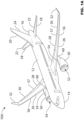
- the aircraft 10A is an exemplary implementation of an aircraft and other types of aircraft are contemplated, such as, but without being limitative, an aircraft 10B illustrated in FIG. 1B .
- the aircraft 10A has a fuselage 12, a cockpit 14 at a front of the fuselage 12 and a tail 16 at a rear of the fuselage 12.
- the tail 16 has left and right horizontal stabilizers 18 and a vertical stabilizer 20.
- Each horizontal stabilizer 18 is provided with an elevator 22 used to control the pitch of the aircraft 10A.
- the vertical stabilizer 20 is provided with a rudder 24 used to control the yaw of the aircraft 10A.
- the aircraft 10A also has a pair of wings 26.
- the left wing 26 is connected to the fuselage 12 and extends on a left side thereof.
- the right wing 26 is connected to the fuselage 12 and extends on a right side thereof.
- the wings 26 are provided with flaps 28 and ailerons 30.
- the flaps 28 are used to control the lift of the aircraft 10A and the ailerons 30 are used to control the roll of the aircraft 10A.
- each wing 26 is provided with a winglet 32 at a tip thereof.
- Left and right engine assemblies 34 are connected to a bottom of the left and right wings 26 respectively, as will be described in greater detail below. It is contemplated that more than one engine assembly 34 could be connected to each wing 26.
- the aircraft 10A is provided with many more components and systems, such as a landing gear and auxiliary power unit, which will not be described herein.
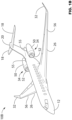
- the aircraft 10B illustrates another embodiment of aircraft.
- Components of the aircraft 10B similar to components of the aircraft 10A are referred to with same reference numbers.
- left and right engine assemblies 34 are connected to rearward left and right portions of the fuselage 12 and not to a bottom of the left and right wings 26 as it is the case for the aircraft 10A.
- the tail of the aircraft 10B also has left and right horizontal stabilizers 18 and a vertical stabilizer 20.
- the left and right horizontal stabilizers 18 of the aircraft 10B are connected to a top portion of the vertical stabilizer 20 so at to form a "T-shaped configuration".
- the left engine assembly 34 a fuel management system 202, one or more fuel tanks 201 and a fuel monitoring system 200 will be described in more detail.
- the right engine assembly 34 is similar to the left engine assembly 34, it will not be described in detail herein. Elements of the right engine assembly 34 that correspond to those of the left engine assembly 34 have been labeled with the same reference in the figures.
- the left engine assembly 34 has a nacelle 50 inside which is an engine 52.
- the engine 52 is a turbofan engine such as the Pratt & Whitney TM PW1500G TM turbofan engine.
- the engine 52 is a turbofan engine from General Electric TM . It is contemplated that other turbofan engines could be used. It is also contemplated that an engine other than a turbofan engine could be used.
- a pylon 54 is connected between the nacelle 50 and a bottom of the left wing 26, thereby connecting the engine 52 to the left wing 26.
- the pylon 54 extends along a top of the nacelle 50. A majority of the pylon 54 extends forward of a leading edge 56 of the left wing 26. The top, rear portion of the pylon 54 connects to the bottom, front portion of the wing 26.
- a pylon 55 is connected between the nacelle 50 and a left side of the fuselage 16, thereby connecting the engine 52 to the fuselage 16.
- the pylon 55 extends along a side of the nacelle 50 on one end and along a rearward side of the fuselage 16 on the other end.
- the engine assembly 34 is also fluidly connected to the fuel management system 202.
- the fuel management system 202 may equally be referred to as an aircraft fuel system.
- the fuel management system 202 may rely on systems and control logic to pump, manage and deliver fuel fluid (equally referred to as jet fuel) so as to ensure that the engine assembly 34 receives a proper amount of fuel fluid at any stage of operations of the aircraft.
- Such stage of operations may comprise operations while the aircraft is stationary on the ground, taxiing and/or in-flight (e.g., during take-off, cruise and/or landing).
- the fuel management system 202 may comprise additional functionalities, such as, but without being limitative, management of a center of gravity of the aircraft by dynamically adjusting allocation of fuel fluid in each one of the fuel tanks.
- the fuel management system 202 may also comprise other functionalities which may become apparent to the person skilled in the art of the present technology.
- the fuel management system 202 comprises one or more fuel tanks 201. Additional systems and components may also be part of the fuel management system 202 such as one or more fuel gauges, one or more fuel pumps, one or more fuel controllers, fuel pipes and/or fuel valves. Such additional systems and components may become readily apparent to the person skilled in the art of the present technology.
- each fuel tank is associated with a corresponding fuel pump and a corresponding fuel gauge.
- each fuel tank may be associated with a plurality of fuel pumps and/or fuel gauges.
- a plurality of fuel tanks may be distributed across the aircraft, such as, but without being limitative, in the wings and/or in the fuselage (e.g., within the belly fairing).
- the fuel tanks may be located externally (e.g., drop tanks attached to a wing).
- the fuel tanks may be "built-in" a structure of the aircraft that is sealed to allow fuel storage.
- the fuel tanks may be located at various portions of the aircraft, such as, but without being limitative, in the wings, in the fuselage and/or empennage of the aircraft.
- FIG. 2 also illustrates "engine #1" which is later refer to as a “first engine” and/or a “left engine” (also referred to as “L Engine”) and “engine #2” which is later refer to as a “second engine” and/or a “right engine” (also referred to as “R Engine”).
- the first engine is later referred to as the first engine 341 and the second engine is later referred to as the second engine 342.
- first engine 341 as the left engine and the second engine 342 as the right engine is simply a convention used to ease the description of the present technology. It should be understood that this aspect is not limitative. Even though reference is made to the first engine 341 and the second engine 342, the number of engines is not limitative. In other words, the present technology may also be directed to aircraft having more than two engines (e.g., two side engines and one central engine, four side engines, etc).
- the first engine 341 and the second engine 342 both comprise fuel flowmeters.
- the fuel flowmeters may allow indicating how much fuel the engines are burning.
- fuel flowmeters may have different accuracies at different consumption rates. They may be designed so as to be more accurate when the aircraft is in cruise condition.
- a first flowmeter associated with the first engine 341 and a second flowmeter associated with the second engine 342 are installed in the fuel line so as to physically measure a volume of fuel travelling through the lines.
- a fuel densitometer may be installed in the one or more fuel tanks 201 so that fuel density may be determined. By multiplying the volume of fuel travelling through the lines with the fuel density, a fuel mass flow rate may be determined.
- fuel flow and “fuel mass flow” will be used interchangeably.
- the present technology is implemented by the fuel monitoring system 200.
- the fuel monitoring system 200 may be a dedicated aircraft system and/or implemented on a system also implementing other functionalities.
- the fuel monitoring system 200 may be part of the aircraft health monitoring system (AHMS).
- the fuel monitoring system may 200 may be part of an engine indication and crew alerting system (EICAS).
- the fuel monitoring system 200 comprises a fuel leak determination system 204.
- the fuel leak determination system 204 may be a sub-system of the fuel monitoring system 200. In some other embodiments, the fuel leak determination system 204 may be the fuel monitoring system 200.
- the first engine 341 and the second engine 342 each transmits data to the fuel leak determination system 204.
- the data relates to the fuel flow associated with each one of the first engine 341 and the second engine 342.
- the data is generated by the flowmeters and is a measurement of the fuel flow of each one of the first engine 341 and the second engine 342.
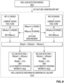
- FIG. 3 a diagram illustrating certain modules of the fuel leak determination system in accordance with embodiments of the present technology is depicted. As previously mentioned, even though reference is made to modules, it is implied that each one of the modules represent performance of process steps which may be executed by hardware that is expressly or implicitly shown.
- the fuel leak determination system 204 illustrated at FIG. 3 comprises a condition determination module 302, a fuel flow determination module 304, a current sensed fuel flow versus baseline fuel flow module 306 and a fuel leak detection module 308. It should be understood that modules 302 to 308 could be sub-divided and/or combined without departing from the scope of the present technology.
- the condition determination module 302 allows determining that the aircraft has reached a stable condition (e.g., cruise) and that the fuel leak detection may be activated.
- the stable condition may be referred to as a first mode of operation.
- reaching the stable condition triggers acquiring a first baseline fuel flow of the first engine and a second baseline fuel flow of the second engine.
- such approach allows increasing an accuracy of the first and second baseline fuel flows as the first and second baseline fuel flows are acquired when the engines are operating at a more stable mode. In the embodiment illustrated at FIG.
- the condition determination module 302 establishes that the stable mode of operation has been reached by executing steps which determine whether certain conditions have been met. As an exemplary embodiment, such steps include steps 402 to 412.
- a first condition is checked by determining whether the aircraft is in flight.
- a second condition is checked by determining whether an altitude is within a predetermined range. In some embodiments, the predetermined range is between 20,000 feet and 51,000 feet.
- a third condition is checked by determining whether a rate of change of the altitude is within a predetermined range. In some embodiments, the predetermined range is between - 400 feet/min and + 400 feet/min.
- a fourth condition is checked by determining whether an air speed of the aircraft is within a predetermined range.
- the predetermined range is between Mach 0.6 and Mach 0.94.
- a fifth condition is checked by determining whether fan speeds of the first engine and of the second engine is within a predetermined range. In some embodiments, the predetermined range is between 60% and 120% fan speed.
- a sixth condition is checked by determining whether a total air temperature (TAT) sensed by the aircraft is within a predetermined range. In some embodiments, the predetermined range is between - 60 Celsius degrees and + 40 Celsius degrees.
- the fuel flow determination module 304 is engaged. In some embodiments, if one or more of the six conditions are not met, a module 310 may be engaged. Further details regarding the module 310 are provided in connection with the description of FIG. 8 .
- the fuel flow determination module 304 allows acquiring the first and second baseline fuel flow of the first and second engines. In some embodiments, the fuel flow determination module 304 is only engaged if determination that the aircraft has reached a stable condition (e.g., cruise) has been met. In some embodiments, the fuel flow determination module 304 allows setting an average actual fuel flow from each engine recorded over a predetermined time span (e.g., 60 seconds). In the illustrated embodiments, data is received from the first and second engines. In some embodiments, the data relates to the fuel flow associated with each one of the first engine 341 and the second engine 342.
- the first baseline fuel flow (Wfbase1) is determined for the first engine and the second baseline fuel flow (Wfbase2) is determined for the second engine.
- This approach allows establishing baseline fuel flows based on actual, in-service data, when the engines are operating in real-life conditions and in accordance with a given mode of operation.
- the first and the second baseline fuel flows are stored temporally or permanently in a non-transitory computer-readable medium so that, once they have been calculated, they can be maintained accessible for later access.
- the module 306 allows comparing current sensed fuel flows with the first and second baseline fuel flows determined by fuel flow determination module 304.
- a first current sensed fuel flow of the first engine (Wf1) is monitored based on the data received from the first engine.
- a second current sensed fuel flow of the second engine (Wf2) is monitored based on the data received from the second engine.
- Wf1 current sensed fuel flow of the first engine
- Wf2 second current sensed fuel flow of the second engine
- the module 306 calculates a first ratio (Wfratio1) associated with the first engine and a second ration (Wfratio2) associated with the second engine.
- the first ratio (Wfratio1) may be calculated as being (Wf1/Wfbase1) and the second ration (Wfratio2) may be calculated as being (Wf2/Wfbase2).
- the module 308 allows triggering detection of a fuel leak.
- the module 308 may not only detect a fuel leak but also detect in which one of the engines the fuel leak occurs.
- the module 308 calculate an absolute difference (Wfsplit) between the first ratio (Wfratio1) and the second ratio (Wfratio2). In other words, Wfsplit may be equal to
- the module 308 detects that a leak occurs at the first engine if the following conditions are met: Wfratio1 > Wfratio2 AND Wfsplit > 10% AND (L & R throttle positions are within 0.3 degree).
- the module 308 detects that a leak occurs at the second engine if the following conditions are met: Wfratio2 > Wfratio1 AND Wfsplit > 10% AND (L & R throttle positions are within 0.3 degree).
- the threshold associated with Wfsplit may vary (e.g., 9%, 11%, etc).
- the L & R throttle positions correspond to a position difference between a first position of a first throttle controlling the first engine and a second position of a second throttle controlling the second engine.
- the threshold associated with the L & R throttle positions may vary (e.g., 0.2 degree, 0.4 degree, etc).
- the fuel monitoring system 200 may inform the pilot and/or co-pilot and/or avionics of the aircraft that a leak has been detected.
- a persistency condition is verified before the fuel monitoring system 200 triggers informing the pilot and/or co-pilot and/or avionics of the aircraft that the leak has been detected.
- the information may further comprise an indication relative to which one of the engines is subjected to a leak.
- values associated with the leak may also be provided (e.g., values determined on the basis of the first ratio and the second ratio).
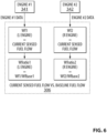
- the module 310 is engaged when the condition determination module 302 determined that one or more of the conditions establishing that the aircraft is in the first mode of operation is not met. This may be the case when the aircraft has not yet reached a stable condition (e.g., aircraft is taking off, aircraft is still climbing, aircraft is engaged in a manoeuvre, aircraft is landing, aircraft is taxiing, etc).
- the module 310 therefore allows detection of a leak even though the aircraft has not reach or is no longer operating according to the first mode of operation.
- the module 310 relies on air speed and/or wheel speed. In some embodiments, the module 310 relies on previously calculated baseline fuel flows.
- the previously calculated baseline fuel flows may have been calculated previously during the flight or during a previous flight.
- the previously calculated baseline fuel flows comprise a first pre-existing baseline fuel flow and a second pre-existing baseline fuel flow accessed from a non-transitory computer-readable medium of the fuel monitoring system 200.
- the module 310 may not only detect a fuel leak but also detect in which one of the engines the fuel leak occurs.
- the module 310 calculates an absolute difference (Wfsplit) between the first ratio (Wfratio1) based on the first pre-existing baseline fuel flow and the second ratio (Wfratio2) based on the second pre-existing baseline fuel flow. In other words, Wfsplit may be equal to
- the module 310 detects that a leak occurs at the first engine if the following conditions are met: Wfratio1 > Wfratio2 AND Wfsplit > 25% AND (L & R throttle positions are within 0.3 degree).
- the module 310 detects that a leak occurs at the second engine if the following conditions are met: Wfratio2 > Wfratio1 AND Wfsplit > 25% AND (L & R throttle positions are within 0.3 degree).
- the threshold associated with Wfsplit may vary (e.g., 24%, 26%, etc).
- the L & R throttle positions correspond to a position difference between a first position of a first throttle controlling the first engine and a second position of a second throttle controlling the second engine.
- the threshold associated with the L & R throttle positions may vary (e.g., 0.2 degree, 0.4 degree, etc).
- the module 310 may be disengaged. At such a stage, the module 308 takes over.
- the fuel monitoring system 200 described in the paragraphs above may allow (1) better refinement in fuel leak detection; (2) identification of faulty engine; and/or (3) leak detection even though the leak occurs downstream of a flowmeter of an engine.
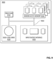
- the computing environment 900 may be implemented by the fuel monitoring system 200.
- the computing environment 900 comprises various hardware components including one or more single or multi-core processors collectively represented by a processor 910, a solid-state drive 920, a random access memory 930 and an input/output interface 950.
- the computing environment 900 may be a computer specifically designed for installation into an aircraft.
- the computing environment 900 may be a generic computer system adapted to meet certain requirements, such as, but not limited to, certification requirements.
- the computing environment 300 may be an "electronic device”, a “controller”, a “fuel controller”, a “control computer”, a “control system”, a “computer-based system”, a “fuel management system”, a “fuel leak determination system”, a “fuel monitoring system” and/or any combination thereof appropriate to the relevant task at hand.
- the computing environment 900 may also be a sub-system of one of the above-listed systems.
- the computing environment 900 may be an "off the shelf” generic computer system.
- the computing environment 900 may also be distributed amongst multiple systems.
- the computing environment 900 may also be specifically dedicated to the implementation of the present technology. As a person in the art of the present technology may appreciate, multiple variations as to how the computing environment 900 is implemented may be envisioned without departing from the scope of the present technology.
- Communication between the various components of the computing environment 900 may be enabled by one or more internal and/or external buses 960 (e.g. a PCI bus, universal serial bus, IEEE 1394 "Firewire” bus, SCSI bus, Serial-ATA bus, ARINC bus, etc.), to which the various hardware components are electronically coupled.
- internal and/or external buses 960 e.g. a PCI bus, universal serial bus, IEEE 1394 "Firewire” bus, SCSI bus, Serial-ATA bus, ARINC bus, etc.
- the input/output interface 950 may be coupled directly and/or indirectly to one or more fuel gauges and/or one or more flowmeters and/or other control systems of the aircraft (e.g., the avionics of the aircraft).
- the solid-state drive 920 stores program instructions suitable for being loaded into the random access memory 930 and executed by the processor 910 for operating a fuel pump management system.
- the program instructions may be part of a library or an application.
- the computing environment 900 may be configured so as to determine that an aircraft has reached a first mode of operation and/or detect a fuel leak in the aircraft.
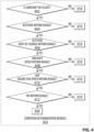
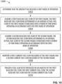
- FIG. 10 a flowchart illustrating a computer-implemented method 1000 of detecting a fuel leak in an aircraft is illustrated.
- the computer-implemented method 1000 may be (completely or partially) implemented on the fuel monitoring system 200.
- the method 1000 may start at step 1002 by determining that the aircraft has reached a first mode of operation. If such determination is made, then the method 1000 proceeds to step 1004.
- determining that the aircraft has reached the first mode of operation comprises determining that the following conditions are met (a) the aircraft is in flight; (b) an altitude of the aircraft is between 20,000 feet (6096 m) and 51,000 feet (15545 m); (c) a rate of change of the altitude is between - 400 feet/min (-122 m/min) and + 400 feet/min (+122 m/min); (d) an air speed of the aircraft is between Mach 0.6 and Mach 0.94; (e) fan speeds of the first engine and of the second engine is between 60% and 120% fan speed; and (f) a total air temperature (TAT) sensed by the aircraft is between - 60 Celsius degrees and + 40 Celsius degrees.
- TAT total air temperature
- the method 1000 proceeds to acquiring a first baseline fuel flow of the first engine, the first baseline fuel flow being determined as an average actual fuel flow of the first engine established over a period of time while operating in accordance with the first mode of operation.
- the method 1000 proceeds to acquiring a second baseline fuel flow of the second engine, the second baseline fuel flow being determined as an average actual fuel flow of the second engine established over the period of time while operating in accordance with the first mode of operation.
- the period of time is 60 seconds.
- the method 1000 proceeds to monitoring a first current fuel flow measured at the first engine and a second current fuel flow measured at the second engine.
- the method 1000 proceeds to triggering a fuel leak detection based on an analysis of the first baseline fuel flow, the first current fuel flow, the second baseline fuel flow and the second current fuel flow.
- the analysis of the first baseline fuel flow, the first current fuel flow, the second baseline fuel flow and the second current fuel flow comprises calculating a first ratio based on the first current fuel flow and the first baseline fuel flow; and calculating a second ratio based on the second current fuel flow and the second baseline fuel flow.
- triggering the fuel leak detection comprises at least one of triggering a first fuel leak detection associated with the first engine and triggering a second fuel leak detection associated with the second engine.
- the first fuel leak detection is triggered based on a determination that the following conditions are met (a) the first ratio is above the second ratio; (b) an absolute value of a difference between the first ratio and the second ratio is above a first predetermined threshold; and (c) a position difference between a first position of a first throttle controlling the first engine and a second position of a second throttle controlling the second engine is below a second predetermined threshold.
- the second fuel leak detection is triggered based on a determination that the following conditions are met (a) the second ratio is above the first ratio; (b) an absolute value of a difference between the first ratio and the second ratio is above a first predetermined threshold; and (c) a position difference between a first position of a first throttle controlling the first engine and a second position of a second throttle controlling the second engine is below a second predetermined threshold.
- the first predetermined threshold is 10% and the second predetermined threshold is 0.3 degree.
- the method further comprises, prior to determining that the first mode of operation has been reached and up until determination that the first mode of operation has been reached accessing, from a non-transitory computer-readable medium, a first pre-existing baseline fuel flow and a second pre-existing baseline fuel flow, the first pre-existing baseline fuel flow and the second pre-existing baseline fuel flow having been acquired during a previous flight of the aircraft; and triggering the fuel leak detection based on an analysis of the first pre-existing baseline fuel flow, the first current fuel flow, the second pre-existing baseline fuel flow and the second current fuel flow.
- the method further comprises, prior to determining that the first mode of operation has been reached and up until determination that the first mode of operation has been reached accessing, from a non-transitory computer-readable medium, a first pre-existing baseline fuel flow and a second pre-existing baseline fuel flow, the first pre-existing baseline fuel flow and the second pre-existing baseline fuel flow having been acquired during a previous flight of the aircraft; and triggering the fuel leak detection based on an analysis of the first pre-existing baseline fuel flow, the first current fuel flow, the second pre-existing baseline fuel flow and the second current fuel flow.
- triggering the fuel leak detection comprises at least one of triggering a first fuel leak detection associated with the first engine and triggering a second fuel leak detection associated with the second engine and wherein the analysis of the first pre-existing baseline fuel flow, the first current fuel flow, the second pre-existing baseline fuel flow and the second current fuel flow comprises calculating a third ratio based on the first current fuel flow and the first pre-existing baseline fuel flow; and calculating a fourth ratio based on the second current fuel flow and the second pre-existing baseline fuel flow.
- the first fuel leak detection is triggered based on a determination that the following conditions are met (a) the third ratio is above the fourth ratio; (b) an absolute value of a difference between the third ratio and the fourth ratio is above a first predetermined threshold; and (c) a position difference between a first position of a first throttle controlling the first engine and a second position of a second throttle controlling the second engine is below a second predetermined threshold.
- the second fuel leak detection is triggered based on a determination that the following conditions are met (a) the fourth ratio is above the third ratio; (b) an absolute value of a difference between the third ratio and the fourth ratio is above a first predetermined threshold; and (c) a position difference between a first position of a first throttle controlling the first engine and a second position of a second throttle controlling the second engine is below a second predetermined threshold.
- the first predetermined threshold is 25% and the second predetermined threshold is 0.3 degrees.
Landscapes
- Engineering & Computer Science (AREA)
- Aviation & Aerospace Engineering (AREA)
- Chemical & Material Sciences (AREA)
- Combustion & Propulsion (AREA)
- Physics & Mathematics (AREA)
- General Physics & Mathematics (AREA)
- Mechanical Engineering (AREA)
- General Engineering & Computer Science (AREA)
- Automation & Control Theory (AREA)
- Combined Controls Of Internal Combustion Engines (AREA)
- Examining Or Testing Airtightness (AREA)
Claims (14)
- Ein rechnerimplementiertes Verfahren zum Detektieren eines Kraftstofflecks in einem Flugzeug (10A, 10B), wobei das Flugzeug ein erstes Triebwerk (341) und ein zweites Triebwerk (342) umfasst, wobei das Verfahren Folgendes umfasst:
beim Bestimmen, dass das Flugzeug einen ersten Betriebsmodus erreicht hat:Erfassen eines ersten Basislinien-Kraftstoffdurchflusses (Wfbase1) des ersten Triebwerks (341), wobei der erste Basislinien-Kraftstoffdurchfluss als durchschnittlicher tatsächlicher Kraftstoffdurchfluss des ersten Triebwerks bestimmt wird, der über einen Zeitraum während des Betreibens gemäß dem ersten Betriebsmodus ermittelt wird;Erfassen eines zweiten Basislinien-Kraftstoffdurchflusses (Wfbase2) des zweiten Triebwerks (342), wobei der zweite Basislinien-Kraftstoffdurchfluss als durchschnittlicher tatsächlicher Kraftstoffdurchfluss des zweiten Triebwerks bestimmt wird, der über den Zeitraum während des Betreibens gemäß dem ersten Betriebsmodus ermittelt wird;Überwachen eines ersten aktuellen Kraftstoffdurchflusses (Wf1), der an dem ersten Triebwerk (341) gemessen wird, und eines zweiten aktuellen Kraftstoffdurchflusses (Wf2), der an dem zweiten Triebwerk (342) gemessen wird; undAuslösen einer Kraftstoffleckdetektion basierend auf einer Analyse des ersten Basislinien-Kraftstoffdurchflusses (Wfbase1), des ersten aktuellen Kraftstoffdurchflusses (Wf1), des zweiten Basislinien-Kraftstoffdurchflusses (Wfbase2) und des zweiten aktuellen Kraftstoffdurchflusses (Wf2);dadurch gekennzeichnet, dass die Analyse des ersten Basislinien-Kraftstoffdurchflusses (Wfbase1), des ersten aktuellen Kraftstoffdurchflusses (Wf1), des zweiten Basislinien-Kraftstoffdurchflusses (Wfbase2) und des zweiten aktuellen Kraftstoffdurchflusses (Wf2) Folgendes umfasst:Berechnen eines ersten Verhältnisses (Wfratio1) basierend auf dem ersten aktuellen Kraftstoffdurchfluss (Wf1) und dem ersten Basislinien-Kraftstoffdurchfluss (Wfbase1); undBerechnen eines zweiten Verhältnisses (Wfratio2) basierend auf dem zweiten aktuellen Kraftstoffdurchfluss (Wf2) und dem zweiten Basislinien-Kraftstoffdurchfluss (Wfbase2). - Ein System (204) zum Detektieren eines Kraftstofflecks in einem Flugzeug (10A, 10B), wobei das Flugzeug ein erstes Triebwerk (341) und ein zweites Triebwerk (342) umfasst, wobei das System Folgendes umfasst:einen Prozessor (910); undein nicht transitorisches rechnerlesbares Medium (920), wobei das transitorische rechnerlesbare Medium Steuerungslogik umfasst, die bei Ausführung durch den Prozessor (910) das System zu Folgendem veranlasst:beim Bestimmen, dass das Flugzeug (10A, 10B) einen ersten Betriebsmodus erreicht hat:Erfassen eines ersten Basislinien-Kraftstoffdurchflusses (Wfbase1) des ersten Triebwerks (341), wobei der erste Basislinien-Kraftstoffdurchfluss als durchschnittlicher tatsächlicher Kraftstoffdurchfluss des ersten Triebwerks bestimmt wird, der über einen Zeitraum während des Betreibens gemäß dem ersten Betriebsmodus ermittelt wird;Erfassen eines zweiten Basislinien-Kraftstoffdurchflusses (Wfbase2) des zweiten Triebwerks (342), wobei der zweite Basislinien-Kraftstoffdurchfluss als durchschnittlicher tatsächlicher Kraftstoffdurchfluss des zweiten Triebwerks bestimmt wird, der über den Zeitraum während des Betreibens gemäß dem ersten Betriebsmodus ermittelt wird;Überwachen eines ersten aktuellen Kraftstoffdurchflusses (Wf1), der an dem ersten Triebwerk (341) gemessen wird, und eines zweiten aktuellen Kraftstoffdurchflusses (Wf2), der an dem zweiten Triebwerk (342) gemessen wird; undAuslösen einer Kraftstoffleckdetektion basierend auf einer Analyse des ersten Basislinien-Kraftstoffdurchflusses (Wfbase1), des ersten aktuellen Kraftstoffdurchflusses (Wf1), des zweiten Basislinien-Kraftstoffdurchflusses (Wfbase2) und des zweiten aktuellen Kraftstoffdurchflusses (Wf2);dadurch gekennzeichnet, dass die Analyse des ersten Basislinien-Kraftstoffdurchflusses (Wfbase1), des ersten aktuellen Kraftstoffdurchflusses (Wf1), des zweiten Basislinien-Kraftstoffdurchflusses (Wfbase2) und des zweiten aktuellen Kraftstoffdurchflusses (Wf2) Folgendes umfasst:Berechnen eines ersten Verhältnisses (Wfratio1) basierend auf dem ersten aktuellen Kraftstoffdurchfluss (Wf1) und dem ersten Basislinien-Kraftstoffdurchfluss (Wfbase1); undBerechnen eines zweiten Verhältnisses (Wfratio2) basierend auf dem zweiten aktuellen Kraftstoffdurchfluss (Wf2) und dem zweiten Basislinien-Kraftstoffdurchfluss (Wfbase2).
- Das Verfahren nach Anspruch 1 oder das System nach Anspruch 2, wobei das Auslösen der Kraftstoffleckdetektion mindestens eines von Auslösen einer ersten mit dem ersten Triebwerk (341) assoziierten Kraftstoffleckdetektion und Auslösen einer zweiten mit dem zweiten Triebwerk (342) assoziierten Kraftstoffleckdetektion umfasst.
- Das Verfahren nach einem der Ansprüche 1 oder 3 oder das System nach einem der Ansprüche 2 oder 3, wobei die erste Kraftstoffleckdetektion basierend auf einer Bestimmung, dass die folgenden Bedingungen erfüllt werden, ausgelöst wird:(a) das erste Verhältnis (Wfratio1) liegt über dem zweiten Verhältnis (Wfratio2);(b) ein Absolutwert einer Differenz (Wfsplit) zwischen dem ersten Verhältnis (Wfratio1) und dem zweiten Verhältnis (Wfratio2) liegt über einer ersten vorbestimmten Schwelle; und(c) eine Positionsdifferenz zwischen einer ersten Position einer ersten Drossel, die das erste Triebwerk (341) steuert, und einer zweiten Position einer zweiten Drossel, die das zweite Triebwerk (342) steuert, liegt unter einer zweiten vorbestimmten Schwelle.
- Das Verfahren oder das System nach Anspruch 4, wobei die zweite Kraftstoffleckdetektion basierend auf einer Bestimmung, dass die folgenden Bedingungen erfüllt werden, ausgelöst wird:(a) das zweite Verhältnis (Wfratio2) liegt über dem ersten Verhältnis (Wfratio1);(b) ein Absolutwert einer Differenz (Wfsplit) zwischen dem ersten Verhältnis (Wfratio1) und dem zweiten Verhältnis (Wfratio2) liegt über einer ersten vorbestimmten Schwelle; und(c) eine Positionsdifferenz zwischen einer ersten Position einer ersten Drossel, die das erste Triebwerk (341) steuert, und einer zweiten Position einer zweiten Drossel, die das zweite Triebwerk (342) steuert, liegt unter einer zweiten vorbestimmten Schwelle.
- Das Verfahren oder das System nach Anspruch 5, wobei die erste vorbestimmte Schwelle 10 % beträgt und die zweite vorbestimmte Schwelle 0,3 Grad beträgt.
- Das Verfahren nach einem der Ansprüche 1 und 3 bis 6 oder das System nach einem der Ansprüche 2 bis 6, wobei das Bestimmen, dass das Flugzeug den ersten Betriebsmodus erreicht hat, das Bestimmen, dass die folgenden Bedingungen erfüllt werden, umfasst:(a) das Flugzeug befindet sich im Flug;(b) eine Höhe des Flugzeugs liegt zwischen 20000 Fuß (6096 m) und 51000 Fuß (15545 m);(c) eine Änderungsrate der Höhe liegt zwischen -400 Fuß/min (-122 m/min) und +400 Fuß/min (+122 m/min);(d) eine Luftgeschwindigkeit des Flugzeugs liegt zwischen Mach 0,6 und Mach 0,94;(e) Fangeschwindigkeiten des ersten Triebwerks (341) und des zweiten Triebwerks (342) liegen zwischen 60 % und 120 % Fangeschwindigkeit; und(f) eine Gesamtlufttemperatur (Total Air Temperature, TAT), die durch das Flugzeug gemessen wird, liegt zwischen -60 Grad Celsius und +40 Grad Celsius.
- Das Verfahren nach einem der Ansprüche 1 und 3 bis 7 oder das System nach einem der Ansprüche 2 bis 7, wobei der Zeitraum 60 Sekunden beträgt.
- Das Verfahren nach einem der Ansprüche 1 und 3 bis 8 oder das System nach einem der Ansprüche 2 bis 8, wobei das Verfahren, vor dem Bestimmen, dass der erste Betriebsmodus erreicht wurde, und bis zu der Bestimmung, dass der erste Betriebsmodus erreicht wurde, ferner Folgendes umfasst:Zugreifen, von einem nicht transitorischen rechnerlesbaren Medium (920), auf einen ersten vorbestehenden Basislinien-Kraftstoffdurchfluss und einen zweiten vorbestehenden Basislinien-Kraftstoffdurchfluss, wobei der erste vorbestehende Basislinien-Kraftstoffdurchfluss und der zweite vorbestehende Basislinien-Kraftstoffdurchfluss während eines vorangegangenen Fluges des Flugzeugs erfasst wurden; undAuslösen einer Kraftstoffleckdetektion basierend auf einer Analyse des ersten vorbestehenden Basislinien-Kraftstoffdurchflusses, des ersten aktuellen Kraftstoffdurchflusses (Wf1), des zweiten vorbestehenden Basislinien-Kraftstoffdurchflusses und des zweiten aktuellen Kraftstoffdurchflusses (Wf2);
- Das Verfahren oder das System nach Anspruch 9, wobei das Auslösen der Kraftstoffleckdetektion mindestens eines von Auslösen einer ersten mit dem ersten Triebwerk (341) assoziierten Kraftstoffleckdetektion und Auslösen einer zweiten mit dem zweiten Triebwerk (342) assoziierten Kraftstoffleckdetektion umfasst und wobei die Analyse des ersten vorbestehenden Basislinien-Kraftstoffdurchflusses, des ersten aktuellen Kraftstoffdurchflusses (Wf1), des zweiten vorbestehenden Basislinien-Kraftstoffdurchflusses und des zweiten aktuellen Kraftstoffdurchflusses (Wf2) Folgendes umfasst:Berechnen eines dritten Verhältnisses basierend auf dem ersten aktuellen Kraftstoffdurchfluss und dem ersten vorbestehenden Basislinien-Kraftstoffdurchfluss; undBerechnen eines vierten Verhältnisses basierend auf dem zweiten aktuellen Kraftstoffdurchfluss und dem zweiten vorbestehenden Basislinien-Kraftstoffdurchfluss.
- Das Verfahren oder das System nach Anspruch 10, wobei die erste Kraftstoffleckdetektion basierend auf einer Bestimmung, dass die folgenden Bedingungen erfüllt werden, ausgelöst wird:(a) das dritte Verhältnis liegt über dem vierten Verhältnis;(b) ein Absolutwert einer Differenz zwischen dem dritten Verhältnis und dem vierten Verhältnis liegt über einer ersten vorbestimmten Schwelle; und(c) eine Positionsdifferenz zwischen einer ersten Position einer ersten Drossel, die das erste Triebwerk (341) steuert, und einer zweiten Position einer zweiten Drossel, die das zweite Triebwerk (342) steuert, liegt unter einer zweiten vorbestimmten Schwelle.
- Das Verfahren oder das System nach Anspruch 11, wobei die zweite Kraftstoffleckdetektion basierend auf einer Bestimmung, dass die folgenden Bedingungen erfüllt werden, ausgelöst wird:(a) das vierte Verhältnis liegt über dem dritten Verhältnis;(b) ein Absolutwert einer Differenz zwischen dem dritten Verhältnis und dem vierten Verhältnis liegt über einer ersten vorbestimmten Schwelle; und(c) eine Positionsdifferenz zwischen einer ersten Position einer ersten Drossel, die das erste Triebwerk (341) steuert, und einer zweiten Position einer zweiten Drossel, die das zweite Triebwerk (342) steuert, liegt unter einer zweiten vorbestimmten Schwelle.
- Das Verfahren oder das System nach Anspruch 12, wobei die erste vorbestimmte Schwelle 25 % beträgt und die zweite vorbestimmte Schwelle 0,3 Grad beträgt.
- Ein Flugzeug (10A, 10B), das das System nach einem der Ansprüche 2 bis 13 aufweist.
Applications Claiming Priority (2)
| Application Number | Priority Date | Filing Date | Title |
|---|---|---|---|
| US201762575590P | 2017-10-23 | 2017-10-23 | |
| PCT/CA2018/051318 WO2019079884A1 (en) | 2017-10-23 | 2018-10-19 | SYSTEM AND METHOD FOR DETECTING FUEL LEAK IN AN AIRCRAFT |
Publications (3)
| Publication Number | Publication Date |
|---|---|
| EP3701240A1 EP3701240A1 (de) | 2020-09-02 |
| EP3701240A4 EP3701240A4 (de) | 2021-07-28 |
| EP3701240B1 true EP3701240B1 (de) | 2024-03-20 |
Family
ID=66247069
Family Applications (1)
| Application Number | Title | Priority Date | Filing Date |
|---|---|---|---|
| EP18871539.5A Active EP3701240B1 (de) | 2017-10-23 | 2018-10-19 | System und verfahren zur detektion eines kraftstofflecks in einem flugzeug |
Country Status (5)
| Country | Link |
|---|---|
| US (1) | US11801943B2 (de) |
| EP (1) | EP3701240B1 (de) |
| CN (1) | CN111279174B (de) |
| CA (1) | CA3079764A1 (de) |
| WO (1) | WO2019079884A1 (de) |
Families Citing this family (6)
| Publication number | Priority date | Publication date | Assignee | Title |
|---|---|---|---|---|
| FR3094086B1 (fr) * | 2019-03-19 | 2021-03-19 | Safran Aircraft Engines | Procédé de surveillance de l’état de fonctionnement d’un bloc hydromécanique |
| GB2593196A (en) * | 2020-03-19 | 2021-09-22 | Airbus Operations Ltd | Aircraft fuel system monitoring |
| GB2607114A (en) * | 2021-05-27 | 2022-11-30 | Airbus Operations Ltd | A method of determining an operating condition of a valve of an aircraft system |
| US12000758B2 (en) | 2021-06-09 | 2024-06-04 | Pratt & Whitney Canada Corp. | Leak detection for pressurized fluid systems |
| US11846568B2 (en) | 2021-06-09 | 2023-12-19 | Pratt & Whitney Canada Corp. | Leak detection for pressurized fluid systems |
| US12571348B2 (en) * | 2024-03-29 | 2026-03-10 | General Electric Company | Fuel leak combustion assembly for igniting a gaseous fuel leaking from a potential leak location |
Family Cites Families (18)
| Publication number | Priority date | Publication date | Assignee | Title |
|---|---|---|---|---|
| US4218744A (en) * | 1978-08-08 | 1980-08-19 | Avicon Development Group | Fuel flow consumption monitoring system |
| US5497653A (en) * | 1992-09-21 | 1996-03-12 | General Electric Company | Method and system for detecting significant hydraulic leaks |
| JP3480108B2 (ja) | 1995-04-04 | 2003-12-15 | 日産自動車株式会社 | ガスエンジンの燃料洩れ検出装置 |
| JP2002310024A (ja) | 2001-04-10 | 2002-10-23 | Nishishiba Electric Co Ltd | 発電装置の燃料漏れ検出方法 |
| GB0421124D0 (en) | 2004-09-22 | 2004-10-27 | Airbus Uk Ltd | Fuel leak estimator |
| NO323418B1 (no) * | 2005-04-20 | 2007-04-30 | Nat Oilwell Norway As | Fremgangsmate for a bestemme lekkasje i en stempelmaskin |
| FR2887226B1 (fr) * | 2005-06-21 | 2008-08-08 | Airbus France Sas | Procede de detection de fuite de carburant dans un moteur d'aeronef et systeme de mise en oeuvre de ce procede |
| US7603242B2 (en) | 2005-09-21 | 2009-10-13 | Airbus Uk Limited | Fuel leak estimator |
| US7739004B2 (en) * | 2006-11-29 | 2010-06-15 | The Boeing Company | Automatic engine fuel flow monitoring and alerting fuel leak detection method |
| US7660494B2 (en) * | 2007-08-13 | 2010-02-09 | The Boeing Company | Fiber optic fuel detection system |
| FR2953557B1 (fr) | 2009-12-07 | 2012-03-02 | Ge Energy Products France Snc | Procede de detection d'une fuite de combustible liquide dans une turbine a gaz |
| CN103380057B (zh) * | 2010-09-29 | 2016-10-05 | 航空机器股份有限公司 | 飞机的无损检测的创新系统和方法 |
| US9140189B2 (en) | 2012-04-11 | 2015-09-22 | General Electric Company | Systems and methods for detecting fuel leaks in gas turbine engines |
| WO2014030555A1 (ja) | 2012-08-21 | 2014-02-27 | 株式会社堀場製作所 | 内燃機関の漏洩燃料測定方法及び漏洩燃料測定装置 |
| ZA201404149B (en) | 2013-06-07 | 2015-07-29 | Der Linde Josef Johannes Van | Fuel management |
| CN103822763A (zh) * | 2014-03-06 | 2014-05-28 | 中国商用飞机有限责任公司 | 用于飞机燃油链路中的燃油泄漏的检测方法 |
| DE102014119210A1 (de) * | 2014-12-19 | 2016-06-23 | Rolls-Royce Deutschland Ltd & Co Kg | Verfahren zur Ermittlung eines Treibstofflecks eines Treibstoffsystems eines wenigstens zwei Triebwerke aufweisenden Flugzeugs |
| US10071818B2 (en) * | 2016-01-13 | 2018-09-11 | The Boeing Company | Systems and methods for providing airplane performance calculations |
-
2018
- 2018-10-19 EP EP18871539.5A patent/EP3701240B1/de active Active
- 2018-10-19 WO PCT/CA2018/051318 patent/WO2019079884A1/en not_active Ceased
- 2018-10-19 CN CN201880068767.4A patent/CN111279174B/zh active Active
- 2018-10-19 CA CA3079764A patent/CA3079764A1/en active Pending
-
2020
- 2020-04-21 US US16/854,571 patent/US11801943B2/en active Active
Also Published As
| Publication number | Publication date |
|---|---|
| US11801943B2 (en) | 2023-10-31 |
| EP3701240A4 (de) | 2021-07-28 |
| US20200262578A1 (en) | 2020-08-20 |
| WO2019079884A1 (en) | 2019-05-02 |
| EP3701240A1 (de) | 2020-09-02 |
| CA3079764A1 (en) | 2019-05-02 |
| CN111279174A (zh) | 2020-06-12 |
| CN111279174B (zh) | 2022-07-01 |
Similar Documents
| Publication | Publication Date | Title |
|---|---|---|
| US11801943B2 (en) | System and method for detecting a fuel leak in an aircraft | |
| EP2676883B1 (de) | Strömungsabrissmanagementsystem | |
| Freeman et al. | Air data system fault modeling and detection | |
| US9731814B2 (en) | Alternative method to determine the air mass state of an aircraft and to validate and augment the primary method | |
| US8527233B2 (en) | Airspeed sensing system for an aircraft | |
| US20130204544A1 (en) | Methods and systems for determining airspeed of an aircraft | |
| BR102013002536B1 (pt) | Sistema para controlar uma aeronave, e método implementado em computador | |
| US11401044B2 (en) | Method and assistance system for detecting a degradation of flight performance | |
| BR112014015911B1 (pt) | sistema de monitoramento de decolagem segura | |
| US12006058B2 (en) | Fuel pump management system and method of operating a fuel pump management system | |
| JP6590419B2 (ja) | 飛行中の航空機周辺の圧力場を制御するシステムおよび方法 | |
| EP3521175B1 (de) | Verfahren und systeme zur steuerung von schub, der von mehreren triebwerken an einem flugzeug erzeugt wird, zur unterstützung bestimmter flugbedingungen | |
| US9733135B2 (en) | Method and device for automatically detecting an incorrect measurement of a total temperature on an aircraft | |
| EP3109608A1 (de) | Detektion von flugzeuggesamtlufttemperaturanomalien | |
| US8602361B2 (en) | Laminar flow monitor | |
| EP2506108B1 (de) | Flugbahnausgleichssystem für Luftgeschwindigkeitsschwankungen | |
| Bennett et al. | CFD simulation of flow around angle of attack and sideslip angle vanes on a BAe Jetstream 3102–part 1 | |
| Milward et al. | Multipoint Angle of Attack Sensing for Avoidance of Loss of Control in Flight | |
| CN107273557B (zh) | 一种上单翼飞机不可用燃油试验方法 | |
| CN115657715A (zh) | 一种用于飞机的飞行控制系统及方法 |
Legal Events
| Date | Code | Title | Description |
|---|---|---|---|
| STAA | Information on the status of an ep patent application or granted ep patent |
Free format text: STATUS: THE INTERNATIONAL PUBLICATION HAS BEEN MADE |
|
| PUAI | Public reference made under article 153(3) epc to a published international application that has entered the european phase |
Free format text: ORIGINAL CODE: 0009012 |
|
| STAA | Information on the status of an ep patent application or granted ep patent |
Free format text: STATUS: REQUEST FOR EXAMINATION WAS MADE |
|
| 17P | Request for examination filed |
Effective date: 20200525 |
|
| AK | Designated contracting states |
Kind code of ref document: A1 Designated state(s): AL AT BE BG CH CY CZ DE DK EE ES FI FR GB GR HR HU IE IS IT LI LT LU LV MC MK MT NL NO PL PT RO RS SE SI SK SM TR |
|
| AX | Request for extension of the european patent |
Extension state: BA ME |
|
| DAV | Request for validation of the european patent (deleted) | ||
| DAX | Request for extension of the european patent (deleted) | ||
| A4 | Supplementary search report drawn up and despatched |
Effective date: 20210624 |
|
| RIC1 | Information provided on ipc code assigned before grant |
Ipc: G01M 3/26 20060101AFI20210618BHEP Ipc: B64D 37/00 20060101ALI20210618BHEP Ipc: F02C 9/46 20060101ALI20210618BHEP |
|
| GRAP | Despatch of communication of intention to grant a patent |
Free format text: ORIGINAL CODE: EPIDOSNIGR1 |
|
| STAA | Information on the status of an ep patent application or granted ep patent |
Free format text: STATUS: GRANT OF PATENT IS INTENDED |
|
| INTG | Intention to grant announced |
Effective date: 20230621 |
|
| GRAS | Grant fee paid |
Free format text: ORIGINAL CODE: EPIDOSNIGR3 |
|
| GRAA | (expected) grant |
Free format text: ORIGINAL CODE: 0009210 |
|
| STAA | Information on the status of an ep patent application or granted ep patent |
Free format text: STATUS: THE PATENT HAS BEEN GRANTED |
|
| AK | Designated contracting states |
Kind code of ref document: B1 Designated state(s): AL AT BE BG CH CY CZ DE DK EE ES FI FR GB GR HR HU IE IS IT LI LT LU LV MC MK MT NL NO PL PT RO RS SE SI SK SM TR |
|
| REG | Reference to a national code |
Ref country code: GB Ref legal event code: FG4D |
|
| REG | Reference to a national code |
Ref country code: CH Ref legal event code: EP |
|
| REG | Reference to a national code |
Ref country code: IE Ref legal event code: FG4D |
|
| REG | Reference to a national code |
Ref country code: DE Ref legal event code: R096 Ref document number: 602018066994 Country of ref document: DE |
|
| PG25 | Lapsed in a contracting state [announced via postgrant information from national office to epo] |
Ref country code: LT Free format text: LAPSE BECAUSE OF FAILURE TO SUBMIT A TRANSLATION OF THE DESCRIPTION OR TO PAY THE FEE WITHIN THE PRESCRIBED TIME-LIMIT Effective date: 20240320 |
|
| REG | Reference to a national code |
Ref country code: LT Ref legal event code: MG9D |
|
| PG25 | Lapsed in a contracting state [announced via postgrant information from national office to epo] |
Ref country code: GR Free format text: LAPSE BECAUSE OF FAILURE TO SUBMIT A TRANSLATION OF THE DESCRIPTION OR TO PAY THE FEE WITHIN THE PRESCRIBED TIME-LIMIT Effective date: 20240621 |
|
| PG25 | Lapsed in a contracting state [announced via postgrant information from national office to epo] |
Ref country code: RS Free format text: LAPSE BECAUSE OF FAILURE TO SUBMIT A TRANSLATION OF THE DESCRIPTION OR TO PAY THE FEE WITHIN THE PRESCRIBED TIME-LIMIT Effective date: 20240620 Ref country code: HR Free format text: LAPSE BECAUSE OF FAILURE TO SUBMIT A TRANSLATION OF THE DESCRIPTION OR TO PAY THE FEE WITHIN THE PRESCRIBED TIME-LIMIT Effective date: 20240320 |
|
| REG | Reference to a national code |
Ref country code: NL Ref legal event code: MP Effective date: 20240320 |
|
| PG25 | Lapsed in a contracting state [announced via postgrant information from national office to epo] |
Ref country code: RS Free format text: LAPSE BECAUSE OF FAILURE TO SUBMIT A TRANSLATION OF THE DESCRIPTION OR TO PAY THE FEE WITHIN THE PRESCRIBED TIME-LIMIT Effective date: 20240620 Ref country code: NO Free format text: LAPSE BECAUSE OF FAILURE TO SUBMIT A TRANSLATION OF THE DESCRIPTION OR TO PAY THE FEE WITHIN THE PRESCRIBED TIME-LIMIT Effective date: 20240620 Ref country code: LT Free format text: LAPSE BECAUSE OF FAILURE TO SUBMIT A TRANSLATION OF THE DESCRIPTION OR TO PAY THE FEE WITHIN THE PRESCRIBED TIME-LIMIT Effective date: 20240320 Ref country code: HR Free format text: LAPSE BECAUSE OF FAILURE TO SUBMIT A TRANSLATION OF THE DESCRIPTION OR TO PAY THE FEE WITHIN THE PRESCRIBED TIME-LIMIT Effective date: 20240320 Ref country code: GR Free format text: LAPSE BECAUSE OF FAILURE TO SUBMIT A TRANSLATION OF THE DESCRIPTION OR TO PAY THE FEE WITHIN THE PRESCRIBED TIME-LIMIT Effective date: 20240621 Ref country code: FI Free format text: LAPSE BECAUSE OF FAILURE TO SUBMIT A TRANSLATION OF THE DESCRIPTION OR TO PAY THE FEE WITHIN THE PRESCRIBED TIME-LIMIT Effective date: 20240320 Ref country code: BG Free format text: LAPSE BECAUSE OF FAILURE TO SUBMIT A TRANSLATION OF THE DESCRIPTION OR TO PAY THE FEE WITHIN THE PRESCRIBED TIME-LIMIT Effective date: 20240320 |
|
| REG | Reference to a national code |
Ref country code: AT Ref legal event code: MK05 Ref document number: 1668221 Country of ref document: AT Kind code of ref document: T Effective date: 20240320 |
|
| PG25 | Lapsed in a contracting state [announced via postgrant information from national office to epo] |
Ref country code: SE Free format text: LAPSE BECAUSE OF FAILURE TO SUBMIT A TRANSLATION OF THE DESCRIPTION OR TO PAY THE FEE WITHIN THE PRESCRIBED TIME-LIMIT Effective date: 20240320 Ref country code: LV Free format text: LAPSE BECAUSE OF FAILURE TO SUBMIT A TRANSLATION OF THE DESCRIPTION OR TO PAY THE FEE WITHIN THE PRESCRIBED TIME-LIMIT Effective date: 20240320 |
|
| PG25 | Lapsed in a contracting state [announced via postgrant information from national office to epo] |
Ref country code: NL Free format text: LAPSE BECAUSE OF FAILURE TO SUBMIT A TRANSLATION OF THE DESCRIPTION OR TO PAY THE FEE WITHIN THE PRESCRIBED TIME-LIMIT Effective date: 20240320 |
|
| PG25 | Lapsed in a contracting state [announced via postgrant information from national office to epo] |
Ref country code: NL Free format text: LAPSE BECAUSE OF FAILURE TO SUBMIT A TRANSLATION OF THE DESCRIPTION OR TO PAY THE FEE WITHIN THE PRESCRIBED TIME-LIMIT Effective date: 20240320 |
|
| PG25 | Lapsed in a contracting state [announced via postgrant information from national office to epo] |
Ref country code: IS Free format text: LAPSE BECAUSE OF FAILURE TO SUBMIT A TRANSLATION OF THE DESCRIPTION OR TO PAY THE FEE WITHIN THE PRESCRIBED TIME-LIMIT Effective date: 20240720 |
|
| PG25 | Lapsed in a contracting state [announced via postgrant information from national office to epo] |
Ref country code: SM Free format text: LAPSE BECAUSE OF FAILURE TO SUBMIT A TRANSLATION OF THE DESCRIPTION OR TO PAY THE FEE WITHIN THE PRESCRIBED TIME-LIMIT Effective date: 20240320 Ref country code: PT Free format text: LAPSE BECAUSE OF FAILURE TO SUBMIT A TRANSLATION OF THE DESCRIPTION OR TO PAY THE FEE WITHIN THE PRESCRIBED TIME-LIMIT Effective date: 20240722 |
|
| PG25 | Lapsed in a contracting state [announced via postgrant information from national office to epo] |
Ref country code: ES Free format text: LAPSE BECAUSE OF FAILURE TO SUBMIT A TRANSLATION OF THE DESCRIPTION OR TO PAY THE FEE WITHIN THE PRESCRIBED TIME-LIMIT Effective date: 20240320 |
|
| PG25 | Lapsed in a contracting state [announced via postgrant information from national office to epo] |
Ref country code: EE Free format text: LAPSE BECAUSE OF FAILURE TO SUBMIT A TRANSLATION OF THE DESCRIPTION OR TO PAY THE FEE WITHIN THE PRESCRIBED TIME-LIMIT Effective date: 20240320 Ref country code: CZ Free format text: LAPSE BECAUSE OF FAILURE TO SUBMIT A TRANSLATION OF THE DESCRIPTION OR TO PAY THE FEE WITHIN THE PRESCRIBED TIME-LIMIT Effective date: 20240320 |
|
| PG25 | Lapsed in a contracting state [announced via postgrant information from national office to epo] |
Ref country code: AT Free format text: LAPSE BECAUSE OF FAILURE TO SUBMIT A TRANSLATION OF THE DESCRIPTION OR TO PAY THE FEE WITHIN THE PRESCRIBED TIME-LIMIT Effective date: 20240320 |
|
| PG25 | Lapsed in a contracting state [announced via postgrant information from national office to epo] |
Ref country code: PL Free format text: LAPSE BECAUSE OF FAILURE TO SUBMIT A TRANSLATION OF THE DESCRIPTION OR TO PAY THE FEE WITHIN THE PRESCRIBED TIME-LIMIT Effective date: 20240320 |
|
| PG25 | Lapsed in a contracting state [announced via postgrant information from national office to epo] |
Ref country code: SK Free format text: LAPSE BECAUSE OF FAILURE TO SUBMIT A TRANSLATION OF THE DESCRIPTION OR TO PAY THE FEE WITHIN THE PRESCRIBED TIME-LIMIT Effective date: 20240320 |
|
| PG25 | Lapsed in a contracting state [announced via postgrant information from national office to epo] |
Ref country code: SM Free format text: LAPSE BECAUSE OF FAILURE TO SUBMIT A TRANSLATION OF THE DESCRIPTION OR TO PAY THE FEE WITHIN THE PRESCRIBED TIME-LIMIT Effective date: 20240320 Ref country code: SK Free format text: LAPSE BECAUSE OF FAILURE TO SUBMIT A TRANSLATION OF THE DESCRIPTION OR TO PAY THE FEE WITHIN THE PRESCRIBED TIME-LIMIT Effective date: 20240320 Ref country code: RO Free format text: LAPSE BECAUSE OF FAILURE TO SUBMIT A TRANSLATION OF THE DESCRIPTION OR TO PAY THE FEE WITHIN THE PRESCRIBED TIME-LIMIT Effective date: 20240320 Ref country code: PT Free format text: LAPSE BECAUSE OF FAILURE TO SUBMIT A TRANSLATION OF THE DESCRIPTION OR TO PAY THE FEE WITHIN THE PRESCRIBED TIME-LIMIT Effective date: 20240722 Ref country code: PL Free format text: LAPSE BECAUSE OF FAILURE TO SUBMIT A TRANSLATION OF THE DESCRIPTION OR TO PAY THE FEE WITHIN THE PRESCRIBED TIME-LIMIT Effective date: 20240320 Ref country code: IS Free format text: LAPSE BECAUSE OF FAILURE TO SUBMIT A TRANSLATION OF THE DESCRIPTION OR TO PAY THE FEE WITHIN THE PRESCRIBED TIME-LIMIT Effective date: 20240720 Ref country code: ES Free format text: LAPSE BECAUSE OF FAILURE TO SUBMIT A TRANSLATION OF THE DESCRIPTION OR TO PAY THE FEE WITHIN THE PRESCRIBED TIME-LIMIT Effective date: 20240320 Ref country code: EE Free format text: LAPSE BECAUSE OF FAILURE TO SUBMIT A TRANSLATION OF THE DESCRIPTION OR TO PAY THE FEE WITHIN THE PRESCRIBED TIME-LIMIT Effective date: 20240320 Ref country code: CZ Free format text: LAPSE BECAUSE OF FAILURE TO SUBMIT A TRANSLATION OF THE DESCRIPTION OR TO PAY THE FEE WITHIN THE PRESCRIBED TIME-LIMIT Effective date: 20240320 Ref country code: AT Free format text: LAPSE BECAUSE OF FAILURE TO SUBMIT A TRANSLATION OF THE DESCRIPTION OR TO PAY THE FEE WITHIN THE PRESCRIBED TIME-LIMIT Effective date: 20240320 |
|
| PG25 | Lapsed in a contracting state [announced via postgrant information from national office to epo] |
Ref country code: IT Free format text: LAPSE BECAUSE OF FAILURE TO SUBMIT A TRANSLATION OF THE DESCRIPTION OR TO PAY THE FEE WITHIN THE PRESCRIBED TIME-LIMIT Effective date: 20240320 |
|
| REG | Reference to a national code |
Ref country code: DE Ref legal event code: R097 Ref document number: 602018066994 Country of ref document: DE |
|
| PG25 | Lapsed in a contracting state [announced via postgrant information from national office to epo] |
Ref country code: IT Free format text: LAPSE BECAUSE OF FAILURE TO SUBMIT A TRANSLATION OF THE DESCRIPTION OR TO PAY THE FEE WITHIN THE PRESCRIBED TIME-LIMIT Effective date: 20240320 |
|
| PG25 | Lapsed in a contracting state [announced via postgrant information from national office to epo] |
Ref country code: DK Free format text: LAPSE BECAUSE OF FAILURE TO SUBMIT A TRANSLATION OF THE DESCRIPTION OR TO PAY THE FEE WITHIN THE PRESCRIBED TIME-LIMIT Effective date: 20240320 |
|
| PLBE | No opposition filed within time limit |
Free format text: ORIGINAL CODE: 0009261 |
|
| STAA | Information on the status of an ep patent application or granted ep patent |
Free format text: STATUS: NO OPPOSITION FILED WITHIN TIME LIMIT |
|
| PG25 | Lapsed in a contracting state [announced via postgrant information from national office to epo] |
Ref country code: DK Free format text: LAPSE BECAUSE OF FAILURE TO SUBMIT A TRANSLATION OF THE DESCRIPTION OR TO PAY THE FEE WITHIN THE PRESCRIBED TIME-LIMIT Effective date: 20240320 |
|
| 26N | No opposition filed |
Effective date: 20241223 |
|
| PG25 | Lapsed in a contracting state [announced via postgrant information from national office to epo] |
Ref country code: SI Free format text: LAPSE BECAUSE OF FAILURE TO SUBMIT A TRANSLATION OF THE DESCRIPTION OR TO PAY THE FEE WITHIN THE PRESCRIBED TIME-LIMIT Effective date: 20240320 |
|
| REG | Reference to a national code |
Ref country code: CH Ref legal event code: PL |
|
| PG25 | Lapsed in a contracting state [announced via postgrant information from national office to epo] |
Ref country code: MC Free format text: LAPSE BECAUSE OF FAILURE TO SUBMIT A TRANSLATION OF THE DESCRIPTION OR TO PAY THE FEE WITHIN THE PRESCRIBED TIME-LIMIT Effective date: 20240320 |
|
| PG25 | Lapsed in a contracting state [announced via postgrant information from national office to epo] |
Ref country code: LU Free format text: LAPSE BECAUSE OF NON-PAYMENT OF DUE FEES Effective date: 20241019 Ref country code: BE Free format text: LAPSE BECAUSE OF NON-PAYMENT OF DUE FEES Effective date: 20241031 |
|
| PG25 | Lapsed in a contracting state [announced via postgrant information from national office to epo] |
Ref country code: CH Free format text: LAPSE BECAUSE OF NON-PAYMENT OF DUE FEES Effective date: 20241031 |
|
| REG | Reference to a national code |
Ref country code: BE Ref legal event code: MM Effective date: 20241031 |
|
| PG25 | Lapsed in a contracting state [announced via postgrant information from national office to epo] |
Ref country code: IE Free format text: LAPSE BECAUSE OF NON-PAYMENT OF DUE FEES Effective date: 20241019 |
|
| PGFP | Annual fee paid to national office [announced via postgrant information from national office to epo] |
Ref country code: DE Payment date: 20251021 Year of fee payment: 8 |
|
| PGFP | Annual fee paid to national office [announced via postgrant information from national office to epo] |
Ref country code: GB Payment date: 20251022 Year of fee payment: 8 |
|
| PGFP | Annual fee paid to national office [announced via postgrant information from national office to epo] |
Ref country code: FR Payment date: 20251030 Year of fee payment: 8 |
|
| PG25 | Lapsed in a contracting state [announced via postgrant information from national office to epo] |
Ref country code: CY Free format text: LAPSE BECAUSE OF FAILURE TO SUBMIT A TRANSLATION OF THE DESCRIPTION OR TO PAY THE FEE WITHIN THE PRESCRIBED TIME-LIMIT; INVALID AB INITIO Effective date: 20181019 |
|
| PG25 | Lapsed in a contracting state [announced via postgrant information from national office to epo] |
Ref country code: HU Free format text: LAPSE BECAUSE OF FAILURE TO SUBMIT A TRANSLATION OF THE DESCRIPTION OR TO PAY THE FEE WITHIN THE PRESCRIBED TIME-LIMIT; INVALID AB INITIO Effective date: 20181019 |