EP3701240B1 - System and method for detecting a fuel leak in an aircraft - Google Patents
System and method for detecting a fuel leak in an aircraft Download PDFInfo
- Publication number
- EP3701240B1 EP3701240B1 EP18871539.5A EP18871539A EP3701240B1 EP 3701240 B1 EP3701240 B1 EP 3701240B1 EP 18871539 A EP18871539 A EP 18871539A EP 3701240 B1 EP3701240 B1 EP 3701240B1
- Authority
- EP
- European Patent Office
- Prior art keywords
- fuel flow
- engine
- ratio
- aircraft
- baseline
- Prior art date
- Legal status (The legal status is an assumption and is not a legal conclusion. Google has not performed a legal analysis and makes no representation as to the accuracy of the status listed.)
- Active
Links
- 239000000446 fuel Substances 0.000 title claims description 298
- 238000000034 method Methods 0.000 title claims description 39
- 238000001514 detection method Methods 0.000 claims description 48
- 238000012544 monitoring process Methods 0.000 claims description 21
- 230000001960 triggered effect Effects 0.000 claims description 12
- 230000008859 change Effects 0.000 claims description 4
- 238000005516 engineering process Methods 0.000 description 34
- 239000002828 fuel tank Substances 0.000 description 15
- 238000010586 diagram Methods 0.000 description 9
- 239000003381 stabilizer Substances 0.000 description 8
- 238000013459 approach Methods 0.000 description 7
- 238000012986 modification Methods 0.000 description 6
- 230000004048 modification Effects 0.000 description 6
- 239000012530 fluid Substances 0.000 description 3
- 239000000523 sample Substances 0.000 description 3
- 230000000712 assembly Effects 0.000 description 2
- 238000000429 assembly Methods 0.000 description 2
- 230000006870 function Effects 0.000 description 2
- 238000005259 measurement Methods 0.000 description 2
- 210000001015 abdomen Anatomy 0.000 description 1
- 230000009194 climbing Effects 0.000 description 1
- 238000004891 communication Methods 0.000 description 1
- 230000005484 gravity Effects 0.000 description 1
- 230000036541 health Effects 0.000 description 1
- 238000009434 installation Methods 0.000 description 1
- 230000000116 mitigating effect Effects 0.000 description 1
- 230000008569 process Effects 0.000 description 1
- 238000012545 processing Methods 0.000 description 1
- 239000007787 solid Substances 0.000 description 1
- 230000007704 transition Effects 0.000 description 1
- 238000011144 upstream manufacturing Methods 0.000 description 1
Images


Classifications
-
- B—PERFORMING OPERATIONS; TRANSPORTING
- B64—AIRCRAFT; AVIATION; COSMONAUTICS
- B64D—EQUIPMENT FOR FITTING IN OR TO AIRCRAFT; FLIGHT SUITS; PARACHUTES; ARRANGEMENTS OR MOUNTING OF POWER PLANTS OR PROPULSION TRANSMISSIONS IN AIRCRAFT
- B64D37/00—Arrangements in connection with fuel supply for power plant
- B64D37/32—Safety measures not otherwise provided for, e.g. preventing explosive conditions
-
- F—MECHANICAL ENGINEERING; LIGHTING; HEATING; WEAPONS; BLASTING
- F02—COMBUSTION ENGINES; HOT-GAS OR COMBUSTION-PRODUCT ENGINE PLANTS
- F02C—GAS-TURBINE PLANTS; AIR INTAKES FOR JET-PROPULSION PLANTS; CONTROLLING FUEL SUPPLY IN AIR-BREATHING JET-PROPULSION PLANTS
- F02C7/00—Features, components parts, details or accessories, not provided for in, or of interest apart form groups F02C1/00 - F02C6/00; Air intakes for jet-propulsion plants
- F02C7/22—Fuel supply systems
-
- B—PERFORMING OPERATIONS; TRANSPORTING
- B64—AIRCRAFT; AVIATION; COSMONAUTICS
- B64D—EQUIPMENT FOR FITTING IN OR TO AIRCRAFT; FLIGHT SUITS; PARACHUTES; ARRANGEMENTS OR MOUNTING OF POWER PLANTS OR PROPULSION TRANSMISSIONS IN AIRCRAFT
- B64D37/00—Arrangements in connection with fuel supply for power plant
-
- B—PERFORMING OPERATIONS; TRANSPORTING
- B64—AIRCRAFT; AVIATION; COSMONAUTICS
- B64D—EQUIPMENT FOR FITTING IN OR TO AIRCRAFT; FLIGHT SUITS; PARACHUTES; ARRANGEMENTS OR MOUNTING OF POWER PLANTS OR PROPULSION TRANSMISSIONS IN AIRCRAFT
- B64D45/00—Aircraft indicators or protectors not otherwise provided for
-
- F—MECHANICAL ENGINEERING; LIGHTING; HEATING; WEAPONS; BLASTING
- F02—COMBUSTION ENGINES; HOT-GAS OR COMBUSTION-PRODUCT ENGINE PLANTS
- F02C—GAS-TURBINE PLANTS; AIR INTAKES FOR JET-PROPULSION PLANTS; CONTROLLING FUEL SUPPLY IN AIR-BREATHING JET-PROPULSION PLANTS
- F02C9/00—Controlling gas-turbine plants; Controlling fuel supply in air- breathing jet-propulsion plants
- F02C9/26—Control of fuel supply
- F02C9/46—Emergency fuel control
-
- G—PHYSICS
- G01—MEASURING; TESTING
- G01M—TESTING STATIC OR DYNAMIC BALANCE OF MACHINES OR STRUCTURES; TESTING OF STRUCTURES OR APPARATUS, NOT OTHERWISE PROVIDED FOR
- G01M3/00—Investigating fluid-tightness of structures
- G01M3/02—Investigating fluid-tightness of structures by using fluid or vacuum
- G01M3/025—Details with respect to the testing of engines or engine parts
-
- G—PHYSICS
- G01—MEASURING; TESTING
- G01M—TESTING STATIC OR DYNAMIC BALANCE OF MACHINES OR STRUCTURES; TESTING OF STRUCTURES OR APPARATUS, NOT OTHERWISE PROVIDED FOR
- G01M3/00—Investigating fluid-tightness of structures
- G01M3/02—Investigating fluid-tightness of structures by using fluid or vacuum
- G01M3/26—Investigating fluid-tightness of structures by using fluid or vacuum by measuring rate of loss or gain of fluid, e.g. by pressure-responsive devices, by flow detectors
-
- G—PHYSICS
- G05—CONTROLLING; REGULATING
- G05B—CONTROL OR REGULATING SYSTEMS IN GENERAL; FUNCTIONAL ELEMENTS OF SUCH SYSTEMS; MONITORING OR TESTING ARRANGEMENTS FOR SUCH SYSTEMS OR ELEMENTS
- G05B23/00—Testing or monitoring of control systems or parts thereof
- G05B23/02—Electric testing or monitoring
- G05B23/0205—Electric testing or monitoring by means of a monitoring system capable of detecting and responding to faults
-
- B—PERFORMING OPERATIONS; TRANSPORTING
- B64—AIRCRAFT; AVIATION; COSMONAUTICS
- B64D—EQUIPMENT FOR FITTING IN OR TO AIRCRAFT; FLIGHT SUITS; PARACHUTES; ARRANGEMENTS OR MOUNTING OF POWER PLANTS OR PROPULSION TRANSMISSIONS IN AIRCRAFT
- B64D45/00—Aircraft indicators or protectors not otherwise provided for
- B64D2045/0085—Devices for aircraft health monitoring, e.g. monitoring flutter or vibration
-
- B—PERFORMING OPERATIONS; TRANSPORTING
- B64—AIRCRAFT; AVIATION; COSMONAUTICS
- B64F—GROUND OR AIRCRAFT-CARRIER-DECK INSTALLATIONS SPECIALLY ADAPTED FOR USE IN CONNECTION WITH AIRCRAFT; DESIGNING, MANUFACTURING, ASSEMBLING, CLEANING, MAINTAINING OR REPAIRING AIRCRAFT, NOT OTHERWISE PROVIDED FOR; HANDLING, TRANSPORTING, TESTING OR INSPECTING AIRCRAFT COMPONENTS, NOT OTHERWISE PROVIDED FOR
- B64F5/00—Designing, manufacturing, assembling, cleaning, maintaining or repairing aircraft, not otherwise provided for; Handling, transporting, testing or inspecting aircraft components, not otherwise provided for
- B64F5/60—Testing or inspecting aircraft components or systems
-
- F—MECHANICAL ENGINEERING; LIGHTING; HEATING; WEAPONS; BLASTING
- F05—INDEXING SCHEMES RELATING TO ENGINES OR PUMPS IN VARIOUS SUBCLASSES OF CLASSES F01-F04
- F05D—INDEXING SCHEME FOR ASPECTS RELATING TO NON-POSITIVE-DISPLACEMENT MACHINES OR ENGINES, GAS-TURBINES OR JET-PROPULSION PLANTS
- F05D2260/00—Function
- F05D2260/80—Diagnostics
-
- F—MECHANICAL ENGINEERING; LIGHTING; HEATING; WEAPONS; BLASTING
- F05—INDEXING SCHEMES RELATING TO ENGINES OR PUMPS IN VARIOUS SUBCLASSES OF CLASSES F01-F04
- F05D—INDEXING SCHEME FOR ASPECTS RELATING TO NON-POSITIVE-DISPLACEMENT MACHINES OR ENGINES, GAS-TURBINES OR JET-PROPULSION PLANTS
- F05D2270/00—Control
- F05D2270/01—Purpose of the control system
- F05D2270/09—Purpose of the control system to cope with emergencies
Definitions
- the present technology relates to systems and methods for detecting fuel leaks in an aircraft.
- the systems and methods allow analysing baseline fuel flows and current fuel flows to trigger a fuel leak detection.
- an undetected fuel leak of an aircraft may cause security risks, in particular when the aircraft is distant from any diversion airport.
- an automatic fuel leak detection system In order to mitigate the risks of undetected fuel leak(s), most aircraft are equipped with an automatic fuel leak detection system.
- such automatic fuel leak detection systems comprise fuel probes located in one or more of the fuel tanks of the aircraft, the fuel probes allow measurement of a quantity of fuel in the one or more fuel tanks.
- the automatic fuel leak detection systems also comprise, for each one of the engines, a flowmeter allowing a reading of a fuel flow rate entering the engine and, from this information, deduce the quantity of fuel consumed by each engine.
- a comparison of a first value of consumption computed from the variation in the quantity of fuel on board since the beginning of the flight (read by the fuel probes) with a second consumption value computed from the flowmeters from the beginning of the flight may enable detection of a fuel leak.
- such approach may only be used to determine a leak in a fuel supply system upstream to the flowmeters (i.e., between the fuel tanks and the flowmeters of the engines) and may have a limited degree of accuracy in detecting a fuel leak.
- triggering the fuel leak detection comprises at least one of triggering a first fuel leak detection associated with the first engine and triggering a second fuel leak detection associated with the second engine.
- the first fuel leak detection is triggered based on a determination that the following conditions are met:
- the second fuel leak detection is triggered based on a determination that the following conditions are met:
- the first predetermined threshold is 10% and the second predeterminec threshold is 0.3 degree.
- determining that the aircraft has reached the first mode of operation comprises determining that the following conditions are met:
- the period of time is 60 seconds.
- the method further comprises, prior to determining that the first mode of operation has been reached and up until determination that the first mode of operation has been reached:
- triggering the fuel leak detection comprises at least one of triggering a first fuel leak detection associated with the first engine and triggering a second fuel leak detection associated with the second engine and wherein the analysis of the first pre-existing baseline fuel flow, the first current fuel flow, the second pre-existing baseline fuel flow and the second current fuel flow comprises:
- the first fuel leak detection is triggered based on a determination that the following conditions are met:
- the second fuel leak detection is triggered based on a determination that the following conditions are met:
- the first predetermined threshold is 25% and the second predeterminec threshold is 0.3 degree.
- various implementations of the present technology provide a non-transitory computer-readable medium storing program instructions for detecting a fuel leak in an aircraft, the program instructions being executable by a processor of a computer-based system to carry out one or more of the above-recited methods.
- a computer system may refer, but is not limited to, an "electronic device”, a “controller”, a “fuel controller”, a “control computer”, a “control system”, a “computer-based system”, a “fuel management system”, a “fuel leak determination system”, a “fuel monitoring system” and/or any combination thereof appropriate to the relevant task at hand.
- computer-readable medium and “memory” are intended to include media of any nature and kind whatsoever, non-limiting examples of which include RAM, ROM, disks (CD-ROMs, DVDs, floppy disks, hard disk drives, etc.), USB keys, flash memory cards, solid state-drives, and tape drives. Still in the context of the present specification, “a” computer-readable medium and “the” computer-readable medium should not be construed as being the same computer-readable medium. To the contrary, and whenever appropriate, "a” computer-readable medium and “the” computer-readable medium may also be construed as a first computer-readable medium and a second computer-readable medium.
- any functional block labeled as a "processor” or a “controller” may be provided through the use of dedicated hardware as well as hardware capable of executing software in association with appropriate software.
- the functions may be provided by a single dedicated processor, by a single shared processor, or by a plurality of individual processors, some of which may be shared.
- the processor may be a general purpose processor, such as a central processing unit (CPU) or a processor dedicated to a specific purpose, such as a digital signal processor (DSP).
- CPU central processing unit
- DSP digital signal processor
- processor or “controller” should not be construed to refer exclusively to hardware capable of executing software, and may implicitly include, without limitation, application specific integrated circuit (ASIC), field programmable gate array (FPGA), read-only memory (ROM) for storing software, random access memory (RAM), and non-volatile storage. Other hardware, conventional and/or custom, may also be included.
- ASIC application specific integrated circuit
- FPGA field programmable gate array
- ROM read-only memory
- RAM random access memory
- non-volatile storage Other hardware, conventional and/or custom, may also be included.
- modules or simply "module(s)" which are implied to be software, may be represented herein as any combination of flowchart elements or other elements indicating performance of process steps and/or textual description. Such modules may be executed by hardware that is expressly or implicitly shown.
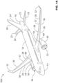
- the aircraft 10A is an exemplary implementation of an aircraft and other types of aircraft are contemplated, such as, but without being limitative, an aircraft 10B illustrated in FIG. 1B .
- the aircraft 10A has a fuselage 12, a cockpit 14 at a front of the fuselage 12 and a tail 16 at a rear of the fuselage 12.
- the tail 16 has left and right horizontal stabilizers 18 and a vertical stabilizer 20.
- Each horizontal stabilizer 18 is provided with an elevator 22 used to control the pitch of the aircraft 10A.
- the vertical stabilizer 20 is provided with a rudder 24 used to control the yaw of the aircraft 10A.
- the aircraft 10A also has a pair of wings 26.
- the left wing 26 is connected to the fuselage 12 and extends on a left side thereof.
- the right wing 26 is connected to the fuselage 12 and extends on a right side thereof.
- the wings 26 are provided with flaps 28 and ailerons 30.
- the flaps 28 are used to control the lift of the aircraft 10A and the ailerons 30 are used to control the roll of the aircraft 10A.
- each wing 26 is provided with a winglet 32 at a tip thereof.
- Left and right engine assemblies 34 are connected to a bottom of the left and right wings 26 respectively, as will be described in greater detail below. It is contemplated that more than one engine assembly 34 could be connected to each wing 26.
- the aircraft 10A is provided with many more components and systems, such as a landing gear and auxiliary power unit, which will not be described herein.
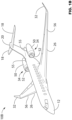
- the aircraft 10B illustrates another embodiment of aircraft.
- Components of the aircraft 10B similar to components of the aircraft 10A are referred to with same reference numbers.
- left and right engine assemblies 34 are connected to rearward left and right portions of the fuselage 12 and not to a bottom of the left and right wings 26 as it is the case for the aircraft 10A.
- the tail of the aircraft 10B also has left and right horizontal stabilizers 18 and a vertical stabilizer 20.
- the left and right horizontal stabilizers 18 of the aircraft 10B are connected to a top portion of the vertical stabilizer 20 so at to form a "T-shaped configuration".
- the left engine assembly 34 a fuel management system 202, one or more fuel tanks 201 and a fuel monitoring system 200 will be described in more detail.
- the right engine assembly 34 is similar to the left engine assembly 34, it will not be described in detail herein. Elements of the right engine assembly 34 that correspond to those of the left engine assembly 34 have been labeled with the same reference in the figures.
- the left engine assembly 34 has a nacelle 50 inside which is an engine 52.
- the engine 52 is a turbofan engine such as the Pratt & Whitney TM PW1500G TM turbofan engine.
- the engine 52 is a turbofan engine from General Electric TM . It is contemplated that other turbofan engines could be used. It is also contemplated that an engine other than a turbofan engine could be used.
- a pylon 54 is connected between the nacelle 50 and a bottom of the left wing 26, thereby connecting the engine 52 to the left wing 26.
- the pylon 54 extends along a top of the nacelle 50. A majority of the pylon 54 extends forward of a leading edge 56 of the left wing 26. The top, rear portion of the pylon 54 connects to the bottom, front portion of the wing 26.
- a pylon 55 is connected between the nacelle 50 and a left side of the fuselage 16, thereby connecting the engine 52 to the fuselage 16.
- the pylon 55 extends along a side of the nacelle 50 on one end and along a rearward side of the fuselage 16 on the other end.
- the engine assembly 34 is also fluidly connected to the fuel management system 202.
- the fuel management system 202 may equally be referred to as an aircraft fuel system.
- the fuel management system 202 may rely on systems and control logic to pump, manage and deliver fuel fluid (equally referred to as jet fuel) so as to ensure that the engine assembly 34 receives a proper amount of fuel fluid at any stage of operations of the aircraft.
- Such stage of operations may comprise operations while the aircraft is stationary on the ground, taxiing and/or in-flight (e.g., during take-off, cruise and/or landing).
- the fuel management system 202 may comprise additional functionalities, such as, but without being limitative, management of a center of gravity of the aircraft by dynamically adjusting allocation of fuel fluid in each one of the fuel tanks.
- the fuel management system 202 may also comprise other functionalities which may become apparent to the person skilled in the art of the present technology.
- the fuel management system 202 comprises one or more fuel tanks 201. Additional systems and components may also be part of the fuel management system 202 such as one or more fuel gauges, one or more fuel pumps, one or more fuel controllers, fuel pipes and/or fuel valves. Such additional systems and components may become readily apparent to the person skilled in the art of the present technology.
- each fuel tank is associated with a corresponding fuel pump and a corresponding fuel gauge.
- each fuel tank may be associated with a plurality of fuel pumps and/or fuel gauges.
- a plurality of fuel tanks may be distributed across the aircraft, such as, but without being limitative, in the wings and/or in the fuselage (e.g., within the belly fairing).
- the fuel tanks may be located externally (e.g., drop tanks attached to a wing).
- the fuel tanks may be "built-in" a structure of the aircraft that is sealed to allow fuel storage.
- the fuel tanks may be located at various portions of the aircraft, such as, but without being limitative, in the wings, in the fuselage and/or empennage of the aircraft.
- FIG. 2 also illustrates "engine #1" which is later refer to as a “first engine” and/or a “left engine” (also referred to as “L Engine”) and “engine #2” which is later refer to as a “second engine” and/or a “right engine” (also referred to as “R Engine”).
- the first engine is later referred to as the first engine 341 and the second engine is later referred to as the second engine 342.
- first engine 341 as the left engine and the second engine 342 as the right engine is simply a convention used to ease the description of the present technology. It should be understood that this aspect is not limitative. Even though reference is made to the first engine 341 and the second engine 342, the number of engines is not limitative. In other words, the present technology may also be directed to aircraft having more than two engines (e.g., two side engines and one central engine, four side engines, etc).
- the first engine 341 and the second engine 342 both comprise fuel flowmeters.
- the fuel flowmeters may allow indicating how much fuel the engines are burning.
- fuel flowmeters may have different accuracies at different consumption rates. They may be designed so as to be more accurate when the aircraft is in cruise condition.
- a first flowmeter associated with the first engine 341 and a second flowmeter associated with the second engine 342 are installed in the fuel line so as to physically measure a volume of fuel travelling through the lines.
- a fuel densitometer may be installed in the one or more fuel tanks 201 so that fuel density may be determined. By multiplying the volume of fuel travelling through the lines with the fuel density, a fuel mass flow rate may be determined.
- fuel flow and “fuel mass flow” will be used interchangeably.
- the present technology is implemented by the fuel monitoring system 200.
- the fuel monitoring system 200 may be a dedicated aircraft system and/or implemented on a system also implementing other functionalities.
- the fuel monitoring system 200 may be part of the aircraft health monitoring system (AHMS).
- the fuel monitoring system may 200 may be part of an engine indication and crew alerting system (EICAS).
- the fuel monitoring system 200 comprises a fuel leak determination system 204.
- the fuel leak determination system 204 may be a sub-system of the fuel monitoring system 200. In some other embodiments, the fuel leak determination system 204 may be the fuel monitoring system 200.
- the first engine 341 and the second engine 342 each transmits data to the fuel leak determination system 204.
- the data relates to the fuel flow associated with each one of the first engine 341 and the second engine 342.
- the data is generated by the flowmeters and is a measurement of the fuel flow of each one of the first engine 341 and the second engine 342.
- FIG. 3 a diagram illustrating certain modules of the fuel leak determination system in accordance with embodiments of the present technology is depicted. As previously mentioned, even though reference is made to modules, it is implied that each one of the modules represent performance of process steps which may be executed by hardware that is expressly or implicitly shown.
- the fuel leak determination system 204 illustrated at FIG. 3 comprises a condition determination module 302, a fuel flow determination module 304, a current sensed fuel flow versus baseline fuel flow module 306 and a fuel leak detection module 308. It should be understood that modules 302 to 308 could be sub-divided and/or combined without departing from the scope of the present technology.
- the condition determination module 302 allows determining that the aircraft has reached a stable condition (e.g., cruise) and that the fuel leak detection may be activated.
- the stable condition may be referred to as a first mode of operation.
- reaching the stable condition triggers acquiring a first baseline fuel flow of the first engine and a second baseline fuel flow of the second engine.
- such approach allows increasing an accuracy of the first and second baseline fuel flows as the first and second baseline fuel flows are acquired when the engines are operating at a more stable mode. In the embodiment illustrated at FIG.
- the condition determination module 302 establishes that the stable mode of operation has been reached by executing steps which determine whether certain conditions have been met. As an exemplary embodiment, such steps include steps 402 to 412.
- a first condition is checked by determining whether the aircraft is in flight.
- a second condition is checked by determining whether an altitude is within a predetermined range. In some embodiments, the predetermined range is between 20,000 feet and 51,000 feet.
- a third condition is checked by determining whether a rate of change of the altitude is within a predetermined range. In some embodiments, the predetermined range is between - 400 feet/min and + 400 feet/min.
- a fourth condition is checked by determining whether an air speed of the aircraft is within a predetermined range.
- the predetermined range is between Mach 0.6 and Mach 0.94.
- a fifth condition is checked by determining whether fan speeds of the first engine and of the second engine is within a predetermined range. In some embodiments, the predetermined range is between 60% and 120% fan speed.
- a sixth condition is checked by determining whether a total air temperature (TAT) sensed by the aircraft is within a predetermined range. In some embodiments, the predetermined range is between - 60 Celsius degrees and + 40 Celsius degrees.
- the fuel flow determination module 304 is engaged. In some embodiments, if one or more of the six conditions are not met, a module 310 may be engaged. Further details regarding the module 310 are provided in connection with the description of FIG. 8 .
- the fuel flow determination module 304 allows acquiring the first and second baseline fuel flow of the first and second engines. In some embodiments, the fuel flow determination module 304 is only engaged if determination that the aircraft has reached a stable condition (e.g., cruise) has been met. In some embodiments, the fuel flow determination module 304 allows setting an average actual fuel flow from each engine recorded over a predetermined time span (e.g., 60 seconds). In the illustrated embodiments, data is received from the first and second engines. In some embodiments, the data relates to the fuel flow associated with each one of the first engine 341 and the second engine 342.
- the first baseline fuel flow (Wfbase1) is determined for the first engine and the second baseline fuel flow (Wfbase2) is determined for the second engine.
- This approach allows establishing baseline fuel flows based on actual, in-service data, when the engines are operating in real-life conditions and in accordance with a given mode of operation.
- the first and the second baseline fuel flows are stored temporally or permanently in a non-transitory computer-readable medium so that, once they have been calculated, they can be maintained accessible for later access.
- the module 306 allows comparing current sensed fuel flows with the first and second baseline fuel flows determined by fuel flow determination module 304.
- a first current sensed fuel flow of the first engine (Wf1) is monitored based on the data received from the first engine.
- a second current sensed fuel flow of the second engine (Wf2) is monitored based on the data received from the second engine.
- Wf1 current sensed fuel flow of the first engine
- Wf2 second current sensed fuel flow of the second engine
- the module 306 calculates a first ratio (Wfratio1) associated with the first engine and a second ration (Wfratio2) associated with the second engine.
- the first ratio (Wfratio1) may be calculated as being (Wf1/Wfbase1) and the second ration (Wfratio2) may be calculated as being (Wf2/Wfbase2).
- the module 308 allows triggering detection of a fuel leak.
- the module 308 may not only detect a fuel leak but also detect in which one of the engines the fuel leak occurs.
- the module 308 calculate an absolute difference (Wfsplit) between the first ratio (Wfratio1) and the second ratio (Wfratio2). In other words, Wfsplit may be equal to
- the module 308 detects that a leak occurs at the first engine if the following conditions are met: Wfratio1 > Wfratio2 AND Wfsplit > 10% AND (L & R throttle positions are within 0.3 degree).
- the module 308 detects that a leak occurs at the second engine if the following conditions are met: Wfratio2 > Wfratio1 AND Wfsplit > 10% AND (L & R throttle positions are within 0.3 degree).
- the threshold associated with Wfsplit may vary (e.g., 9%, 11%, etc).
- the L & R throttle positions correspond to a position difference between a first position of a first throttle controlling the first engine and a second position of a second throttle controlling the second engine.
- the threshold associated with the L & R throttle positions may vary (e.g., 0.2 degree, 0.4 degree, etc).
- the fuel monitoring system 200 may inform the pilot and/or co-pilot and/or avionics of the aircraft that a leak has been detected.
- a persistency condition is verified before the fuel monitoring system 200 triggers informing the pilot and/or co-pilot and/or avionics of the aircraft that the leak has been detected.
- the information may further comprise an indication relative to which one of the engines is subjected to a leak.
- values associated with the leak may also be provided (e.g., values determined on the basis of the first ratio and the second ratio).
- the module 310 is engaged when the condition determination module 302 determined that one or more of the conditions establishing that the aircraft is in the first mode of operation is not met. This may be the case when the aircraft has not yet reached a stable condition (e.g., aircraft is taking off, aircraft is still climbing, aircraft is engaged in a manoeuvre, aircraft is landing, aircraft is taxiing, etc).
- the module 310 therefore allows detection of a leak even though the aircraft has not reach or is no longer operating according to the first mode of operation.
- the module 310 relies on air speed and/or wheel speed. In some embodiments, the module 310 relies on previously calculated baseline fuel flows.
- the previously calculated baseline fuel flows may have been calculated previously during the flight or during a previous flight.
- the previously calculated baseline fuel flows comprise a first pre-existing baseline fuel flow and a second pre-existing baseline fuel flow accessed from a non-transitory computer-readable medium of the fuel monitoring system 200.
- the module 310 may not only detect a fuel leak but also detect in which one of the engines the fuel leak occurs.
- the module 310 calculates an absolute difference (Wfsplit) between the first ratio (Wfratio1) based on the first pre-existing baseline fuel flow and the second ratio (Wfratio2) based on the second pre-existing baseline fuel flow. In other words, Wfsplit may be equal to
- the module 310 detects that a leak occurs at the first engine if the following conditions are met: Wfratio1 > Wfratio2 AND Wfsplit > 25% AND (L & R throttle positions are within 0.3 degree).
- the module 310 detects that a leak occurs at the second engine if the following conditions are met: Wfratio2 > Wfratio1 AND Wfsplit > 25% AND (L & R throttle positions are within 0.3 degree).
- the threshold associated with Wfsplit may vary (e.g., 24%, 26%, etc).
- the L & R throttle positions correspond to a position difference between a first position of a first throttle controlling the first engine and a second position of a second throttle controlling the second engine.
- the threshold associated with the L & R throttle positions may vary (e.g., 0.2 degree, 0.4 degree, etc).
- the module 310 may be disengaged. At such a stage, the module 308 takes over.
- the fuel monitoring system 200 described in the paragraphs above may allow (1) better refinement in fuel leak detection; (2) identification of faulty engine; and/or (3) leak detection even though the leak occurs downstream of a flowmeter of an engine.
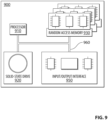
- the computing environment 900 may be implemented by the fuel monitoring system 200.
- the computing environment 900 comprises various hardware components including one or more single or multi-core processors collectively represented by a processor 910, a solid-state drive 920, a random access memory 930 and an input/output interface 950.
- the computing environment 900 may be a computer specifically designed for installation into an aircraft.
- the computing environment 900 may be a generic computer system adapted to meet certain requirements, such as, but not limited to, certification requirements.
- the computing environment 300 may be an "electronic device”, a “controller”, a “fuel controller”, a “control computer”, a “control system”, a “computer-based system”, a “fuel management system”, a “fuel leak determination system”, a “fuel monitoring system” and/or any combination thereof appropriate to the relevant task at hand.
- the computing environment 900 may also be a sub-system of one of the above-listed systems.
- the computing environment 900 may be an "off the shelf” generic computer system.
- the computing environment 900 may also be distributed amongst multiple systems.
- the computing environment 900 may also be specifically dedicated to the implementation of the present technology. As a person in the art of the present technology may appreciate, multiple variations as to how the computing environment 900 is implemented may be envisioned without departing from the scope of the present technology.
- Communication between the various components of the computing environment 900 may be enabled by one or more internal and/or external buses 960 (e.g. a PCI bus, universal serial bus, IEEE 1394 "Firewire” bus, SCSI bus, Serial-ATA bus, ARINC bus, etc.), to which the various hardware components are electronically coupled.
- internal and/or external buses 960 e.g. a PCI bus, universal serial bus, IEEE 1394 "Firewire” bus, SCSI bus, Serial-ATA bus, ARINC bus, etc.
- the input/output interface 950 may be coupled directly and/or indirectly to one or more fuel gauges and/or one or more flowmeters and/or other control systems of the aircraft (e.g., the avionics of the aircraft).
- the solid-state drive 920 stores program instructions suitable for being loaded into the random access memory 930 and executed by the processor 910 for operating a fuel pump management system.
- the program instructions may be part of a library or an application.
- the computing environment 900 may be configured so as to determine that an aircraft has reached a first mode of operation and/or detect a fuel leak in the aircraft.
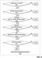
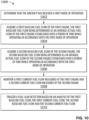
- FIG. 10 a flowchart illustrating a computer-implemented method 1000 of detecting a fuel leak in an aircraft is illustrated.
- the computer-implemented method 1000 may be (completely or partially) implemented on the fuel monitoring system 200.
- the method 1000 may start at step 1002 by determining that the aircraft has reached a first mode of operation. If such determination is made, then the method 1000 proceeds to step 1004.
- determining that the aircraft has reached the first mode of operation comprises determining that the following conditions are met (a) the aircraft is in flight; (b) an altitude of the aircraft is between 20,000 feet (6096 m) and 51,000 feet (15545 m); (c) a rate of change of the altitude is between - 400 feet/min (-122 m/min) and + 400 feet/min (+122 m/min); (d) an air speed of the aircraft is between Mach 0.6 and Mach 0.94; (e) fan speeds of the first engine and of the second engine is between 60% and 120% fan speed; and (f) a total air temperature (TAT) sensed by the aircraft is between - 60 Celsius degrees and + 40 Celsius degrees.
- TAT total air temperature
- the method 1000 proceeds to acquiring a first baseline fuel flow of the first engine, the first baseline fuel flow being determined as an average actual fuel flow of the first engine established over a period of time while operating in accordance with the first mode of operation.
- the method 1000 proceeds to acquiring a second baseline fuel flow of the second engine, the second baseline fuel flow being determined as an average actual fuel flow of the second engine established over the period of time while operating in accordance with the first mode of operation.
- the period of time is 60 seconds.
- the method 1000 proceeds to monitoring a first current fuel flow measured at the first engine and a second current fuel flow measured at the second engine.
- the method 1000 proceeds to triggering a fuel leak detection based on an analysis of the first baseline fuel flow, the first current fuel flow, the second baseline fuel flow and the second current fuel flow.
- the analysis of the first baseline fuel flow, the first current fuel flow, the second baseline fuel flow and the second current fuel flow comprises calculating a first ratio based on the first current fuel flow and the first baseline fuel flow; and calculating a second ratio based on the second current fuel flow and the second baseline fuel flow.
- triggering the fuel leak detection comprises at least one of triggering a first fuel leak detection associated with the first engine and triggering a second fuel leak detection associated with the second engine.
- the first fuel leak detection is triggered based on a determination that the following conditions are met (a) the first ratio is above the second ratio; (b) an absolute value of a difference between the first ratio and the second ratio is above a first predetermined threshold; and (c) a position difference between a first position of a first throttle controlling the first engine and a second position of a second throttle controlling the second engine is below a second predetermined threshold.
- the second fuel leak detection is triggered based on a determination that the following conditions are met (a) the second ratio is above the first ratio; (b) an absolute value of a difference between the first ratio and the second ratio is above a first predetermined threshold; and (c) a position difference between a first position of a first throttle controlling the first engine and a second position of a second throttle controlling the second engine is below a second predetermined threshold.
- the first predetermined threshold is 10% and the second predetermined threshold is 0.3 degree.
- the method further comprises, prior to determining that the first mode of operation has been reached and up until determination that the first mode of operation has been reached accessing, from a non-transitory computer-readable medium, a first pre-existing baseline fuel flow and a second pre-existing baseline fuel flow, the first pre-existing baseline fuel flow and the second pre-existing baseline fuel flow having been acquired during a previous flight of the aircraft; and triggering the fuel leak detection based on an analysis of the first pre-existing baseline fuel flow, the first current fuel flow, the second pre-existing baseline fuel flow and the second current fuel flow.
- the method further comprises, prior to determining that the first mode of operation has been reached and up until determination that the first mode of operation has been reached accessing, from a non-transitory computer-readable medium, a first pre-existing baseline fuel flow and a second pre-existing baseline fuel flow, the first pre-existing baseline fuel flow and the second pre-existing baseline fuel flow having been acquired during a previous flight of the aircraft; and triggering the fuel leak detection based on an analysis of the first pre-existing baseline fuel flow, the first current fuel flow, the second pre-existing baseline fuel flow and the second current fuel flow.
- triggering the fuel leak detection comprises at least one of triggering a first fuel leak detection associated with the first engine and triggering a second fuel leak detection associated with the second engine and wherein the analysis of the first pre-existing baseline fuel flow, the first current fuel flow, the second pre-existing baseline fuel flow and the second current fuel flow comprises calculating a third ratio based on the first current fuel flow and the first pre-existing baseline fuel flow; and calculating a fourth ratio based on the second current fuel flow and the second pre-existing baseline fuel flow.
- the first fuel leak detection is triggered based on a determination that the following conditions are met (a) the third ratio is above the fourth ratio; (b) an absolute value of a difference between the third ratio and the fourth ratio is above a first predetermined threshold; and (c) a position difference between a first position of a first throttle controlling the first engine and a second position of a second throttle controlling the second engine is below a second predetermined threshold.
- the second fuel leak detection is triggered based on a determination that the following conditions are met (a) the fourth ratio is above the third ratio; (b) an absolute value of a difference between the third ratio and the fourth ratio is above a first predetermined threshold; and (c) a position difference between a first position of a first throttle controlling the first engine and a second position of a second throttle controlling the second engine is below a second predetermined threshold.
- the first predetermined threshold is 25% and the second predetermined threshold is 0.3 degrees.
Description
- The present application claims priority to
U.S. Provisional Patent Application No. 62/575,590, filed October 23, 2017 - The present technology relates to systems and methods for detecting fuel leaks in an aircraft. In particular, the systems and methods allow analysing baseline fuel flows and current fuel flows to trigger a fuel leak detection.
- Presence of an undetected fuel leak of an aircraft may cause security risks, in particular when the aircraft is distant from any diversion airport. In order to mitigate the risks of undetected fuel leak(s), most aircraft are equipped with an automatic fuel leak detection system. Typically, such automatic fuel leak detection systems comprise fuel probes located in one or more of the fuel tanks of the aircraft, the fuel probes allow measurement of a quantity of fuel in the one or more fuel tanks. The automatic fuel leak detection systems also comprise, for each one of the engines, a flowmeter allowing a reading of a fuel flow rate entering the engine and, from this information, deduce the quantity of fuel consumed by each engine. In some approaches, a comparison of a first value of consumption computed from the variation in the quantity of fuel on board since the beginning of the flight (read by the fuel probes) with a second consumption value computed from the flowmeters from the beginning of the flight may enable detection of a fuel leak. Amongst other limitations, such approach may only be used to determine a leak in a fuel supply system upstream to the flowmeters (i.e., between the fuel tanks and the flowmeters of the engines) and may have a limited degree of accuracy in detecting a fuel leak.
- Alternative approaches have therefore been developed, such as the method described in
U.S. Patent 7,739,004 to The Boeing Company . The method monitors and alerts a fuel leak downstream of an engine fuel flowmeter in an aircraft. The method uses existing engine sensor data to input into predetermined parameter model to predict the nominal fuel flow and also compares fuel flow between a left engine and a right engine. Even though such an approach may provide benefits, it may still present limitations, in particular due to the "one predetermined parameter model" fits for all engines which may need to require relatively "high" error margins. Patent documentUS8,387,440 discloses a method for detecting a fuel leak in an aircraft. - Improvements may therefore still be desirable.
- The subject matter discussed in the background section should not be assumed to be prior art merely as a result of its mention in the background section. Similarly, a problem mentioned in the background section or associated with the subject matter of the background section should not be assumed to have been previously recognized in the prior art. The subject matter in the background section merely represents different approaches.
- Aspects of the invention provide a method and a system as claimed in the appended claims. According to the invention there is provided a computer-implemented method of detecting a fuel leak in an aircraft as defined in
claim 1. - In a preferred embodiment, triggering the fuel leak detection comprises at least one of triggering a first fuel leak detection associated with the first engine and triggering a second fuel leak detection associated with the second engine.
- In another preferred embodiment, the first fuel leak detection is triggered based on a determination that the following conditions are met:
- (a) the first ratio is above the second ratio;
- (b) an absolute value of a difference between the first ratio and the second ratio is above a first predetermined threshold; and
- (c) a position difference between a first position of a first throttle controlling the first engine and a second position of a second throttle controlling the second engine is below a second predetermined threshold.
- In yet another preferred embodiment, the second fuel leak detection is triggered based on a determination that the following conditions are met:
- (a) the second ratio is above the first ratio;
- (b) an absolute value of a difference between the first ratio and the second ratio is above a first predetermined threshold; and
- (c) a position difference between a first position of a first throttle controlling the first engine and a second position of a second throttle controlling the second engine is below a second predetermined threshold.
- In another preferred embodiment, the first predetermined threshold is 10% and the second predeterminec threshold is 0.3 degree.
- In yet another preferred embodiment, determining that the aircraft has reached the first mode of operation comprises determining that the following conditions are met:
- (a) the aircraft is in flight;
- (b) an altitude of the aircraft is between 20,000 feet and 51,000 feet;
- (c) a rate of change of the altitude is between - 400 feet/min and + 400 feet/min;
- (d) an air speed of the aircraft is between Mach 0.6 and Mach 0.94;
- (e) fan speeds of the first engine and of the second engine is between 60% and 120% fan speed; and
- (f) a total air temperature (TAT) sensed by the aircraft is between - 60 Celsius degrees and + 40 Celsius degrees.
- In another preferred embodiment, the period of time is 60 seconds.
- In yet another preferred embodiment, the method further comprises, prior to determining that the first mode of operation has been reached and up until determination that the first mode of operation has been reached:
- accessing, from a non-transitory computer-readable medium, a first pre-existing baseline fuel flow and a second pre-existing baseline fuel flow, the first pre-existing baseline fuel flow and the second pre-existing baseline fuel flow having been acquired during a previous flight of the aircraft; and
- triggering the fuel leak detection based on an analysis of the first pre-existing baseline fuel flow, the first current fuel flow, the second pre-existing baseline fuel flow and the second current fuel flow.
- In another preferred embodiment, triggering the fuel leak detection comprises at least one of triggering a first fuel leak detection associated with the first engine and triggering a second fuel leak detection associated with the second engine and wherein the analysis of the first pre-existing baseline fuel flow, the first current fuel flow, the second pre-existing baseline fuel flow and the second current fuel flow comprises:
- calculating a third ratio based on the first current fuel flow and the first pre-existing baseline fuel flow; and
- calculating a fourth ratio based on the second current fuel flow and the second pre-existing baseline fuel flow.
- In yet another preferred embodiment, the first fuel leak detection is triggered based on a determination that the following conditions are met:
- (a) the third ratio is above the fourth ratio;
- (b) an absolute value of a difference between the third ratio and the fourth ratio is above a first predetermined threshold; and
- (c) a position difference between a first position of a first throttle controlling the first engine and a second position of a second throttle controlling the second engine is below a second predetermined threshold.
- In another preferred embodiment, the second fuel leak detection is triggered based on a determination that the following conditions are met:
- (a) the fourth ratio is above the third ratio;
- (b) an absolute value of a difference between the third ratio and the fourth ratio is above a first predetermined threshold; and
- (c) a position difference between a first position of a first throttle controlling the first engine and a second position of a second throttle controlling the second engine is below a second predetermined threshold.
- In yet another preferred embodiment, the first predetermined threshold is 25% and the second predeterminec threshold is 0.3 degree.
- According to the invention there is also provided a system for detecting a fuel leak in an aircraft as defined in
claim 2. - In other embodiments, various implementations of the present technology provide a non-transitory computer-readable medium storing program instructions for detecting a fuel leak in an aircraft, the program instructions being executable by a processor of a computer-based system to carry out one or more of the above-recited methods.
- In the context of the present specification, unless expressly provided otherwise, a computer system may refer, but is not limited to, an "electronic device", a "controller", a "fuel controller", a "control computer", a "control system", a "computer-based system", a "fuel management system", a "fuel leak determination system", a "fuel monitoring system" and/or any combination thereof appropriate to the relevant task at hand.
- In the context of the present specification, unless expressly provided otherwise, the expression "computer-readable medium" and "memory" are intended to include media of any nature and kind whatsoever, non-limiting examples of which include RAM, ROM, disks (CD-ROMs, DVDs, floppy disks, hard disk drives, etc.), USB keys, flash memory cards, solid state-drives, and tape drives. Still in the context of the present specification, "a" computer-readable medium and "the" computer-readable medium should not be construed as being the same computer-readable medium. To the contrary, and whenever appropriate, "a" computer-readable medium and "the" computer-readable medium may also be construed as a first computer-readable medium and a second computer-readable medium.
- In the context of the present specification, unless expressly provided otherwise, the words "first", "second", "third", etc. have been used as adjectives only for the purpose of allowing for distinction between the nouns that they modify from one another, and not for the purpose of describing any particular relationship between those nouns.
- For a better understanding of the present technology, as well as other aspects and further features thereof, reference is made to the following description which is to be used in conjunction with the accompanying drawings, where:
-
Figure 1A is a perspective view taken from a top, front, left side of an embodiment of an aircraft; -
Figure 1B is a front view of another embodiment of an aircraft; -
Figure 2 is a diagram of a fuel monitoring system in accordance with an embodiment of the present technology; -
Figure 3-8 are diagrams illustrating certain modules of the fuel monitoring system ofFigure 2 ; -
Figure 9 is a diagram of a computing environment in accordance with an embodiment of the present technology; and -
Figure 10 is a diagram illustrating a flowchart illustrating a computer-implemented method implementing embodiments of the present technology. - It should also be noted that, unless otherwise explicitly specified herein, the drawings are not to scale.
- The examples and conditional language recited herein are principally intended to aid the reader in understanding the principles of the present technology and not to limit its scope to such specifically recited examples and conditions.
- Furthermore, as an aid to understanding, the following description may describe relatively simplified implementations of the present technology. As persons skilled in the art would understand, various implementations of the present technology may be of a greater complexity.
- In some cases, what are believed to be helpful examples of modifications to the present technology may also be set forth. This is done merely as an aid to understanding, and, again, not to define the scope or set forth the bounds of the present technology. These modifications are not an exhaustive list, and a person skilled in the art may make other modifications while nonetheless remaining within the scope of the present technology. Further, where no examples of modifications have been set forth, it should not be interpreted that no modifications are possible and/or that what is described is the sole manner of implementing that element of the present technology.
- Moreover, all statements herein reciting principles, aspects, and implementations of the present technology, as well as specific examples thereof, are intended to encompass both structural and functional equivalents thereof, whether they are currently known or developed in the future. Thus, for example, it will be appreciated by those skilled in the art that any block diagrams herein represent conceptual views of illustrative circuitry embodying the principles of the present technology. Similarly, it will be appreciated that any flowcharts, flow diagrams, state transition diagrams, pseudo-code, and the like represent various processes which may be substantially represented in computer-readable media and so executed by a computer or processor, whether or not such computer or processor is explicitly shown.
- The functions of the various elements shown in the figures, including any functional block labeled as a "processor" or a "controller", may be provided through the use of dedicated hardware as well as hardware capable of executing software in association with appropriate software. When provided by a processor, the functions may be provided by a single dedicated processor, by a single shared processor, or by a plurality of individual processors, some of which may be shared. In some embodiments of the present technology, the processor may be a general purpose processor, such as a central processing unit (CPU) or a processor dedicated to a specific purpose, such as a digital signal processor (DSP). Moreover, explicit use of the term "processor" or "controller" should not be construed to refer exclusively to hardware capable of executing software, and may implicitly include, without limitation, application specific integrated circuit (ASIC), field programmable gate array (FPGA), read-only memory (ROM) for storing software, random access memory (RAM), and non-volatile storage. Other hardware, conventional and/or custom, may also be included.
- Software modules, or simply "module(s)" which are implied to be software, may be represented herein as any combination of flowchart elements or other elements indicating performance of process steps and/or textual description. Such modules may be executed by hardware that is expressly or implicitly shown.
- With these fundamentals in place, we will now consider some non-limiting examples to illustrate various implementations of aspects of the present technology.
- Referring to
FIG. 1A , there is shown anaircraft 10A. Theaircraft 10A is an exemplary implementation of an aircraft and other types of aircraft are contemplated, such as, but without being limitative, anaircraft 10B illustrated inFIG. 1B . Theaircraft 10A has afuselage 12, acockpit 14 at a front of thefuselage 12 and atail 16 at a rear of thefuselage 12. Thetail 16 has left and righthorizontal stabilizers 18 and avertical stabilizer 20. Eachhorizontal stabilizer 18 is provided with anelevator 22 used to control the pitch of theaircraft 10A. Thevertical stabilizer 20 is provided with arudder 24 used to control the yaw of theaircraft 10A. Theaircraft 10A also has a pair ofwings 26. Theleft wing 26 is connected to thefuselage 12 and extends on a left side thereof. Theright wing 26 is connected to thefuselage 12 and extends on a right side thereof. Thewings 26 are provided withflaps 28 andailerons 30. Theflaps 28 are used to control the lift of theaircraft 10A and theailerons 30 are used to control the roll of theaircraft 10A. Optionally, eachwing 26 is provided with awinglet 32 at a tip thereof. Left andright engine assemblies 34 are connected to a bottom of the left andright wings 26 respectively, as will be described in greater detail below. It is contemplated that more than oneengine assembly 34 could be connected to eachwing 26. Theaircraft 10A is provided with many more components and systems, such as a landing gear and auxiliary power unit, which will not be described herein. - Turning now to
FIG. 1B , theaircraft 10B illustrates another embodiment of aircraft. Components of theaircraft 10B similar to components of theaircraft 10A are referred to with same reference numbers. As can be seen fromFIG. 1B , left andright engine assemblies 34 are connected to rearward left and right portions of thefuselage 12 and not to a bottom of the left andright wings 26 as it is the case for theaircraft 10A. The tail of theaircraft 10B also has left and righthorizontal stabilizers 18 and avertical stabilizer 20. Contrary to the configuration of theaircraft 10A, the left and righthorizontal stabilizers 18 of theaircraft 10B are connected to a top portion of thevertical stabilizer 20 so at to form a "T-shaped configuration". - Referring now concurrently to
FIG. 1A ,1B and2 , theleft engine assembly 34, afuel management system 202, one ormore fuel tanks 201 and afuel monitoring system 200 will be described in more detail. As theright engine assembly 34 is similar to theleft engine assembly 34, it will not be described in detail herein. Elements of theright engine assembly 34 that correspond to those of theleft engine assembly 34 have been labeled with the same reference in the figures. - In both the
aircraft 10A and theaircraft 10B, theleft engine assembly 34 has anacelle 50 inside which is anengine 52. In the present implementation of theaircraft 10A, theengine 52 is a turbofan engine such as the Pratt & Whitney™ PW1500G™ turbofan engine. In the present implementation of theaircraft 10B, theengine 52 is a turbofan engine from General Electric™. It is contemplated that other turbofan engines could be used. It is also contemplated that an engine other than a turbofan engine could be used. - In the aircraft embodiment illustrated by the
aircraft 10A, apylon 54 is connected between thenacelle 50 and a bottom of theleft wing 26, thereby connecting theengine 52 to theleft wing 26. Thepylon 54 extends along a top of thenacelle 50. A majority of thepylon 54 extends forward of aleading edge 56 of theleft wing 26. The top, rear portion of thepylon 54 connects to the bottom, front portion of thewing 26. - In the aircraft embodiment illustrated by the
aircraft 10B, apylon 55 is connected between thenacelle 50 and a left side of thefuselage 16, thereby connecting theengine 52 to thefuselage 16. Thepylon 55 extends along a side of thenacelle 50 on one end and along a rearward side of thefuselage 16 on the other end. - As can be seen in
FIG. 2 , theengine assembly 34 is also fluidly connected to thefuel management system 202. In some embodiments, thefuel management system 202 may equally be referred to as an aircraft fuel system. Broadly speaking thefuel management system 202 may rely on systems and control logic to pump, manage and deliver fuel fluid (equally referred to as jet fuel) so as to ensure that theengine assembly 34 receives a proper amount of fuel fluid at any stage of operations of the aircraft. Such stage of operations may comprise operations while the aircraft is stationary on the ground, taxiing and/or in-flight (e.g., during take-off, cruise and/or landing). In some embodiments, thefuel management system 202 may comprise additional functionalities, such as, but without being limitative, management of a center of gravity of the aircraft by dynamically adjusting allocation of fuel fluid in each one of the fuel tanks. Thefuel management system 202 may also comprise other functionalities which may become apparent to the person skilled in the art of the present technology. - In the illustrated embodiment, the
fuel management system 202 comprises one ormore fuel tanks 201. Additional systems and components may also be part of thefuel management system 202 such as one or more fuel gauges, one or more fuel pumps, one or more fuel controllers, fuel pipes and/or fuel valves. Such additional systems and components may become readily apparent to the person skilled in the art of the present technology. - The number of fuel tanks, fuel gauges and fuel pumps may vary depending on the configuration of the aircraft. In some embodiments, each fuel tank is associated with a corresponding fuel pump and a corresponding fuel gauge. In some alternative embodiments, each fuel tank may be associated with a plurality of fuel pumps and/or fuel gauges. In some embodiments, a plurality of fuel tanks may be distributed across the aircraft, such as, but without being limitative, in the wings and/or in the fuselage (e.g., within the belly fairing). In some alternative embodiments, such as in fighter jets, the fuel tanks may be located externally (e.g., drop tanks attached to a wing).
- In some embodiments, the fuel tanks may be "built-in" a structure of the aircraft that is sealed to allow fuel storage. As previously mentioned, the fuel tanks may be located at various portions of the aircraft, such as, but without being limitative, in the wings, in the fuselage and/or empennage of the aircraft.
-
FIG. 2 also illustrates "engine # 1" which is later refer to as a "first engine" and/or a "left engine" (also referred to as "L Engine") and "engine # 2" which is later refer to as a "second engine" and/or a "right engine" (also referred to as "R Engine"). The first engine is later referred to as thefirst engine 341 and the second engine is later referred to as thesecond engine 342. It should be understood that reference to thefirst engine 341 as the left engine and thesecond engine 342 as the right engine is simply a convention used to ease the description of the present technology. It should be understood that this aspect is not limitative. Even though reference is made to thefirst engine 341 and thesecond engine 342, the number of engines is not limitative. In other words, the present technology may also be directed to aircraft having more than two engines (e.g., two side engines and one central engine, four side engines, etc). - In some embodiments, the
first engine 341 and thesecond engine 342 both comprise fuel flowmeters. The fuel flowmeters may allow indicating how much fuel the engines are burning. In some embodiments, fuel flowmeters may have different accuracies at different consumption rates. They may be designed so as to be more accurate when the aircraft is in cruise condition. In some embodiments, a first flowmeter associated with thefirst engine 341 and a second flowmeter associated with thesecond engine 342 are installed in the fuel line so as to physically measure a volume of fuel travelling through the lines. In some embodiments, a fuel densitometer may be installed in the one ormore fuel tanks 201 so that fuel density may be determined. By multiplying the volume of fuel travelling through the lines with the fuel density, a fuel mass flow rate may be determined. To ease description of the present technology, "fuel flow" and "fuel mass flow" will be used interchangeably. - In some embodiments, the present technology is implemented by the
fuel monitoring system 200. In some embodiments, thefuel monitoring system 200 may be a dedicated aircraft system and/or implemented on a system also implementing other functionalities. As an example, but without being limitative, thefuel monitoring system 200 may be part of the aircraft health monitoring system (AHMS). In some embodiments, the fuel monitoring system may 200 may be part of an engine indication and crew alerting system (EICAS). In some embodiments, thefuel monitoring system 200 comprises a fuelleak determination system 204. In some embodiments, the fuelleak determination system 204 may be a sub-system of thefuel monitoring system 200. In some other embodiments, the fuelleak determination system 204 may be thefuel monitoring system 200. - In the embodiment illustrated at
FIG. 2 , thefirst engine 341 and thesecond engine 342 each transmits data to the fuelleak determination system 204. In some embodiments, the data relates to the fuel flow associated with each one of thefirst engine 341 and thesecond engine 342. In some embodiments, the data is generated by the flowmeters and is a measurement of the fuel flow of each one of thefirst engine 341 and thesecond engine 342. - Turning now to
FIG. 3 , a diagram illustrating certain modules of the fuel leak determination system in accordance with embodiments of the present technology is depicted. As previously mentioned, even though reference is made to modules, it is implied that each one of the modules represent performance of process steps which may be executed by hardware that is expressly or implicitly shown. - The fuel
leak determination system 204 illustrated atFIG. 3 comprises acondition determination module 302, a fuelflow determination module 304, a current sensed fuel flow versus baselinefuel flow module 306 and a fuelleak detection module 308. It should be understood thatmodules 302 to 308 could be sub-divided and/or combined without departing from the scope of the present technology. - Reference being now made to
FIG. 4 , an embodiment of thecondition determination module 302 is illustrated. In some embodiments, thecondition determination module 302 allows determining that the aircraft has reached a stable condition (e.g., cruise) and that the fuel leak detection may be activated. In some embodiments, the stable condition may be referred to as a first mode of operation. In some embodiments, reaching the stable condition triggers acquiring a first baseline fuel flow of the first engine and a second baseline fuel flow of the second engine. In some embodiments, such approach allows increasing an accuracy of the first and second baseline fuel flows as the first and second baseline fuel flows are acquired when the engines are operating at a more stable mode. In the embodiment illustrated atFIG. 4 , thecondition determination module 302 establishes that the stable mode of operation has been reached by executing steps which determine whether certain conditions have been met. As an exemplary embodiment, such steps includesteps 402 to 412. Atstep 402, a first condition is checked by determining whether the aircraft is in flight. Atstep 404, a second condition is checked by determining whether an altitude is within a predetermined range. In some embodiments, the predetermined range is between 20,000 feet and 51,000 feet. Atstep 406, a third condition is checked by determining whether a rate of change of the altitude is within a predetermined range. In some embodiments, the predetermined range is between - 400 feet/min and + 400 feet/min. Atstep 408, a fourth condition is checked by determining whether an air speed of the aircraft is within a predetermined range. In some embodiments, the predetermined range is between Mach 0.6 and Mach 0.94. Atstep 410, a fifth condition is checked by determining whether fan speeds of the first engine and of the second engine is within a predetermined range. In some embodiments, the predetermined range is between 60% and 120% fan speed. Atstep 412, a sixth condition is checked by determining whether a total air temperature (TAT) sensed by the aircraft is within a predetermined range. In some embodiments, the predetermined range is between - 60 Celsius degrees and + 40 Celsius degrees. - In some embodiments, if all six conditions of the
condition determination module 302 are met, then the fuelflow determination module 304 is engaged. In some embodiments, if one or more of the six conditions are not met, amodule 310 may be engaged. Further details regarding themodule 310 are provided in connection with the description ofFIG. 8 . - Reference being now made to
FIG. 5 , an embodiment of the fuelflow determination module 304 is illustrated. In some embodiments, the fuelflow determination module 304 allows acquiring the first and second baseline fuel flow of the first and second engines. In some embodiments, the fuelflow determination module 304 is only engaged if determination that the aircraft has reached a stable condition (e.g., cruise) has been met. In some embodiments, the fuelflow determination module 304 allows setting an average actual fuel flow from each engine recorded over a predetermined time span (e.g., 60 seconds). In the illustrated embodiments, data is received from the first and second engines. In some embodiments, the data relates to the fuel flow associated with each one of thefirst engine 341 and thesecond engine 342. In some embodiments, the first baseline fuel flow (Wfbase1) is determined for the first engine and the second baseline fuel flow (Wfbase2) is determined for the second engine. This approach allows establishing baseline fuel flows based on actual, in-service data, when the engines are operating in real-life conditions and in accordance with a given mode of operation. In some embodiments, the first and the second baseline fuel flows are stored temporally or permanently in a non-transitory computer-readable medium so that, once they have been calculated, they can be maintained accessible for later access. - Reference being now made to
FIG. 6 , an embodiment of themodule 306 is illustrated. In some embodiments, themodule 306 allows comparing current sensed fuel flows with the first and second baseline fuel flows determined by fuelflow determination module 304. In some embodiments, a first current sensed fuel flow of the first engine (Wf1) is monitored based on the data received from the first engine. A second current sensed fuel flow of the second engine (Wf2) is monitored based on the data received from the second engine. In some embodiments, it is considered that two or more engines operating on a given aircraft at stable conditions should operate at comparable fuel flows for an entire mission, within a reasonable tolerance band. - In some embodiments, once the first mode of operation has been reached, the
module 306 calculates a first ratio (Wfratio1) associated with the first engine and a second ration (Wfratio2) associated with the second engine. The first ratio (Wfratio1) may be calculated as being (Wf1/Wfbase1) and the second ration (Wfratio2) may be calculated as being (Wf2/Wfbase2). - Reference being now made to
FIG. 7 , an embodiment of themodule 308 is illustrated. In some embodiments, themodule 308 allows triggering detection of a fuel leak. In some embodiments, themodule 308 may not only detect a fuel leak but also detect in which one of the engines the fuel leak occurs. In some embodiments, themodule 308 calculate an absolute difference (Wfsplit) between the first ratio (Wfratio1) and the second ratio (Wfratio2). In other words, Wfsplit may be equal to |Wfratio1 - Wfratio2|. - In some embodiments, the
module 308 detects that a leak occurs at the first engine if the following conditions are met:
Wfratio1 > Wfratio2 AND Wfsplit > 10% AND (L & R throttle positions are within 0.3 degree). - In some embodiments, the
module 308 detects that a leak occurs at the second engine if the following conditions are met:
Wfratio2 > Wfratio1 AND Wfsplit > 10% AND (L & R throttle positions are within 0.3 degree). - In some embodiments, the threshold associated with Wfsplit may vary (e.g., 9%, 11%, etc). In some embodiments, the L & R throttle positions correspond to a position difference between a first position of a first throttle controlling the first engine and a second position of a second throttle controlling the second engine. In some embodiments, the threshold associated with the L & R throttle positions may vary (e.g., 0.2 degree, 0.4 degree, etc).
- In some embodiments, once a leak is detected by the
module 308, thefuel monitoring system 200 may inform the pilot and/or co-pilot and/or avionics of the aircraft that a leak has been detected. In some embodiments, a persistency condition is verified before thefuel monitoring system 200 triggers informing the pilot and/or co-pilot and/or avionics of the aircraft that the leak has been detected. The information may further comprise an indication relative to which one of the engines is subjected to a leak. In addition, values associated with the leak may also be provided (e.g., values determined on the basis of the first ratio and the second ratio). This may therefore allow the pilot and/or co-pilot to take corrective measures early on, at a time when mitigation actions may be put in place (e.g., deporting the aircraft to a nearby airport, transferring fuel between fuel tanks, shutting down the engine associated with the leak, etc.). - Reference being now made to
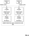
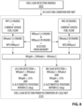
FIG. 8 , an embodiment of themodule 310 is illustrated. In some embodiments, themodule 310 is engaged when thecondition determination module 302 determined that one or more of the conditions establishing that the aircraft is in the first mode of operation is not met. This may be the case when the aircraft has not yet reached a stable condition (e.g., aircraft is taking off, aircraft is still climbing, aircraft is engaged in a manoeuvre, aircraft is landing, aircraft is taxiing, etc). Themodule 310 therefore allows detection of a leak even though the aircraft has not reach or is no longer operating according to the first mode of operation. In some embodiments, themodule 310 relies on air speed and/or wheel speed. In some embodiments, themodule 310 relies on previously calculated baseline fuel flows. The previously calculated baseline fuel flows may have been calculated previously during the flight or during a previous flight. In some embodiments, the previously calculated baseline fuel flows comprise a first pre-existing baseline fuel flow and a second pre-existing baseline fuel flow accessed from a non-transitory computer-readable medium of thefuel monitoring system 200. In some embodiments, themodule 310 may not only detect a fuel leak but also detect in which one of the engines the fuel leak occurs. In some embodiments, themodule 310 calculates an absolute difference (Wfsplit) between the first ratio (Wfratio1) based on the first pre-existing baseline fuel flow and the second ratio (Wfratio2) based on the second pre-existing baseline fuel flow. In other words, Wfsplit may be equal to |Wfratio1 - Wfratio2|. - In some embodiments, the
module 310 detects that a leak occurs at the first engine if the following conditions are met:
Wfratio1 > Wfratio2 AND Wfsplit > 25% AND (L & R throttle positions are within 0.3 degree). - In some embodiments, the
module 310 detects that a leak occurs at the second engine if the following conditions are met:
Wfratio2 > Wfratio1 AND Wfsplit > 25% AND (L & R throttle positions are within 0.3 degree). - In some embodiments, the threshold associated with Wfsplit may vary (e.g., 24%, 26%, etc). In some embodiments, the L & R throttle positions correspond to a position difference between a first position of a first throttle controlling the first engine and a second position of a second throttle controlling the second engine. In some embodiments, the threshold associated with the L & R throttle positions may vary (e.g., 0.2 degree, 0.4 degree, etc).
- In some embodiments, once the conditions monitored by the
condition determination module 302 are met, then themodule 310 may be disengaged. At such a stage, themodule 308 takes over. - Amongst multiple benefits, the
fuel monitoring system 200 described in the paragraphs above may allow (1) better refinement in fuel leak detection; (2) identification of faulty engine; and/or (3) leak detection even though the leak occurs downstream of a flowmeter of an engine. - Turning now to
FIG. 9 , a diagram of acomputing environment 900 in accordance with an embodiment of the present technology is shown. In some embodiments, thecomputing environment 900 may be implemented by thefuel monitoring system 200. In some embodiments, thecomputing environment 900 comprises various hardware components including one or more single or multi-core processors collectively represented by aprocessor 910, a solid-state drive 920, arandom access memory 930 and an input/output interface 950. Thecomputing environment 900 may be a computer specifically designed for installation into an aircraft. In some alternative embodiments, thecomputing environment 900 may be a generic computer system adapted to meet certain requirements, such as, but not limited to, certification requirements. The computing environment 300 may be an "electronic device", a "controller", a "fuel controller", a "control computer", a "control system", a "computer-based system", a "fuel management system", a "fuel leak determination system", a "fuel monitoring system" and/or any combination thereof appropriate to the relevant task at hand. In some embodiments, thecomputing environment 900 may also be a sub-system of one of the above-listed systems. In some other embodiments, thecomputing environment 900 may be an "off the shelf" generic computer system. In some embodiments, thecomputing environment 900 may also be distributed amongst multiple systems. Thecomputing environment 900 may also be specifically dedicated to the implementation of the present technology. As a person in the art of the present technology may appreciate, multiple variations as to how thecomputing environment 900 is implemented may be envisioned without departing from the scope of the present technology. - Communication between the various components of the
computing environment 900 may be enabled by one or more internal and/or external buses 960 (e.g. a PCI bus, universal serial bus, IEEE 1394 "Firewire" bus, SCSI bus, Serial-ATA bus, ARINC bus, etc.), to which the various hardware components are electronically coupled. - The input/
output interface 950 may be coupled directly and/or indirectly to one or more fuel gauges and/or one or more flowmeters and/or other control systems of the aircraft (e.g., the avionics of the aircraft). - According to implementations of the present technology, the solid-
state drive 920 stores program instructions suitable for being loaded into therandom access memory 930 and executed by theprocessor 910 for operating a fuel pump management system. For example, the program instructions may be part of a library or an application. - In some embodiments, the
computing environment 900 may be configured so as to determine that an aircraft has reached a first mode of operation and/or detect a fuel leak in the aircraft. - Turning now to
FIG. 10 , a flowchart illustrating a computer-implementedmethod 1000 of detecting a fuel leak in an aircraft is illustrated. In some embodiments, the computer-implementedmethod 1000 may be (completely or partially) implemented on thefuel monitoring system 200. - The
method 1000 may start atstep 1002 by determining that the aircraft has reached a first mode of operation. If such determination is made, then themethod 1000 proceeds to step 1004. In some embodiments, determining that the aircraft has reached the first mode of operation comprises determining that the following conditions are met (a) the aircraft is in flight; (b) an altitude of the aircraft is between 20,000 feet (6096 m) and 51,000 feet (15545 m); (c) a rate of change of the altitude is between - 400 feet/min (-122 m/min) and + 400 feet/min (+122 m/min); (d) an air speed of the aircraft is between Mach 0.6 and Mach 0.94; (e) fan speeds of the first engine and of the second engine is between 60% and 120% fan speed; and (f) a total air temperature (TAT) sensed by the aircraft is between - 60 Celsius degrees and + 40 Celsius degrees. - At a
step 1004, themethod 1000 proceeds to acquiring a first baseline fuel flow of the first engine, the first baseline fuel flow being determined as an average actual fuel flow of the first engine established over a period of time while operating in accordance with the first mode of operation. At astep 1006, themethod 1000 proceeds to acquiring a second baseline fuel flow of the second engine, the second baseline fuel flow being determined as an average actual fuel flow of the second engine established over the period of time while operating in accordance with the first mode of operation. In some embodiments, the period of time is 60 seconds. - At a
step 1008, themethod 1000 proceeds to monitoring a first current fuel flow measured at the first engine and a second current fuel flow measured at the second engine. - At a
step 1010, themethod 1000 proceeds to triggering a fuel leak detection based on an analysis of the first baseline fuel flow, the first current fuel flow, the second baseline fuel flow and the second current fuel flow. - In some embodiments, the analysis of the first baseline fuel flow, the first current fuel flow, the second baseline fuel flow and the second current fuel flow comprises calculating a first ratio based on the first current fuel flow and the first baseline fuel flow; and calculating a second ratio based on the second current fuel flow and the second baseline fuel flow.
- In some embodiments, triggering the fuel leak detection comprises at least one of triggering a first fuel leak detection associated with the first engine and triggering a second fuel leak detection associated with the second engine.
- In some embodiments, the first fuel leak detection is triggered based on a determination that the following conditions are met (a) the first ratio is above the second ratio; (b) an absolute value of a difference between the first ratio and the second ratio is above a first predetermined threshold; and (c) a position difference between a first position of a first throttle controlling the first engine and a second position of a second throttle controlling the second engine is below a second predetermined threshold.
- In some embodiments, the second fuel leak detection is triggered based on a determination that the following conditions are met (a) the second ratio is above the first ratio; (b) an absolute value of a difference between the first ratio and the second ratio is above a first predetermined threshold; and (c) a position difference between a first position of a first throttle controlling the first engine and a second position of a second throttle controlling the second engine is below a second predetermined threshold.
- In some embodiments, the first predetermined threshold is 10% and the second predetermined threshold is 0.3 degree.
- In some embodiments, the method further comprises, prior to determining that the first mode of operation has been reached and up until determination that the first mode of operation has been reached accessing, from a non-transitory computer-readable medium, a first pre-existing baseline fuel flow and a second pre-existing baseline fuel flow, the first pre-existing baseline fuel flow and the second pre-existing baseline fuel flow having been acquired during a previous flight of the aircraft; and triggering the fuel leak detection based on an analysis of the first pre-existing baseline fuel flow, the first current fuel flow, the second pre-existing baseline fuel flow and the second current fuel flow.
- In some embodiments, the method further comprises, prior to determining that the first mode of operation has been reached and up until determination that the first mode of operation has been reached accessing, from a non-transitory computer-readable medium, a first pre-existing baseline fuel flow and a second pre-existing baseline fuel flow, the first pre-existing baseline fuel flow and the second pre-existing baseline fuel flow having been acquired during a previous flight of the aircraft; and triggering the fuel leak detection based on an analysis of the first pre-existing baseline fuel flow, the first current fuel flow, the second pre-existing baseline fuel flow and the second current fuel flow.
- In some embodiments, triggering the fuel leak detection comprises at least one of triggering a first fuel leak detection associated with the first engine and triggering a second fuel leak detection associated with the second engine and wherein the analysis of the first pre-existing baseline fuel flow, the first current fuel flow, the second pre-existing baseline fuel flow and the second current fuel flow comprises calculating a third ratio based on the first current fuel flow and the first pre-existing baseline fuel flow; and calculating a fourth ratio based on the second current fuel flow and the second pre-existing baseline fuel flow.
- In some embodiments, the first fuel leak detection is triggered based on a determination that the following conditions are met (a) the third ratio is above the fourth ratio; (b) an absolute value of a difference between the third ratio and the fourth ratio is above a first predetermined threshold; and (c) a position difference between a first position of a first throttle controlling the first engine and a second position of a second throttle controlling the second engine is below a second predetermined threshold.
- In some embodiments, the second fuel leak detection is triggered based on a determination that the following conditions are met (a) the fourth ratio is above the third ratio; (b) an absolute value of a difference between the third ratio and the fourth ratio is above a first predetermined threshold; and (c) a position difference between a first position of a first throttle controlling the first engine and a second position of a second throttle controlling the second engine is below a second predetermined threshold.
- In some embodiments, the first predetermined threshold is 25% and the second predetermined threshold is 0.3 degrees.
- While the above-described implementations have been described and shown with reference to particular steps performed in a particular order, it will be understood that these steps may be combined, sub-divided, or re-ordered without departing from the teachings of the present technology. At least some of the steps may be executed in parallel or in series. Accordingly, the order and grouping of the steps is not a limitation of the present technology.
- Modifications and improvements to the above-described implementations of the present technology may become apparent to those skilled in the art. The foregoing description is intended to be exemplary rather than limiting. The scope of the present technology is therefore intended to be limited solely by the scope of the appended claims.
Claims (14)
- A computer-implemented method of detecting a fuel leak in an aircraft (10A, 10B), the aircraft comprising a first engine (341) and a second engine (342), the method comprising:
upon determining that the aircraft has reached a first mode of operation:acquiring a first baseline fuel flow (Wfbase1) of the first engine (341), the first baseline fuel flow being determined as an average actual fuel flow of the first engine established over a period of time while operating in accordance with the first mode of operation;acquiring a second baseline fuel flow (Wfbase2) of the second engine (342), the second baseline fuel flow being determined as an average actual fuel flow of the second engine established over the period of time while operating in accordance with the first mode of operation;monitoring a first current fuel flow (Wf1) measured at the first engine (341) and a second current fuel flow (Wf2) measured at the second engine (342); andtriggering a fuel leak detection based on an analysis of the first baseline fuel flow Wfbase1), the first current fuel flow (Wf1), the second baseline fuel flow (Wfbase2) and the second current fuel flow (Wf2);characterised in that the analysis of the first baseline fuel flow (Wfbase1), the first current fuel flow (Wf1), the second baseline fuel flow (Wfbase2) and the second current fuel flow (Wf2) comprises:calculating a first ratio (Wfratio1) based on the first current fuel flow (Wf1) and the first baseline fuel flow (Wfbase1); andcalculating a second ratio (Wfratio2) based on the second current fuel flow (Wf2) and the second baseline fuel flow (Wfbase2). - A system (204) for detecting a fuel leak in an aircraft (10A, 10B), the aircraft comprising a first engine (341) and a second engine (342), the system comprising:a processor (910); anda non-transitory computer-readable medium (920), the non-transitory computer-readable medium comprising control logic which, upon execution by the processor (910), causes the system to:upon determining that the aircraft (10A, 10B) has reached a first mode of operation:acquire a first baseline fuel flow (Wfbase1) of the first engine (341), the first baseline fuel flow being determined as an average actual fuel flow of the first engine established over a period of time while operating in accordance with the first mode of operation;acquire a second baseline fuel flow (Wfbase2) of the second engine (342), the second baseline fuel flow being determined as an average actual fuel flow of the second engine established over the period of time while operating in accordance with the first mode of operation;monitor a first current fuel flow (Wf1) measured at the first engine (341) and a second current fuel flow (Wf2) measured at the second engine (342); andtrigger a fuel leak detection based on an analysis of the first baseline fuel flow (Wfbase1), the first current fuel flow (Wf1), the second baseline fuel flow (Wfbase2) and the second current fuel flow (Wf2);characterised in that the analysis of the first baseline fuel flow (Wfbase1), the first current fuel flow (Wf1), the second baseline fuel flow (Wfbase2) and the second current fuel flow (Wf2) comprises:calculating a first ratio (Wfratio1) based on the first current fuel flow (Wf1) and the first baseline fuel flow (Wfbase1); andcalculating a second ratio (Wfratio2) based on the second current fuel flow (Wf2) and the second baseline fuel flow (Wfbase2).
- The method of claim 1 or the system of claim 2, wherein triggering the fuel leak detection comprises at least one of triggering a first fuel leak detection associated with the first engine (341) and triggering a second fuel leak detection associated with the second engine (342).
- The method of any one of claims 1 or 3 or the system of any one of claims 2 or 3, wherein the first fuel leak detection is triggered based on a determination that the following conditions are met:(a) the first ratio (Wfratio1) is above the second ratio (Wfratio2);(b) an absolute value of a difference (Wfsplit) between the first ratio (Wfratio1) and the second ratio (Wfratio2) is above a first predetermined threshold; and(c) a position difference between a first position of a first throttle controlling the first engine (341) and a second position of a second throttle controlling the second engine (342) is below a second predetermined threshold.
- The method or the system of claim 4, wherein the second fuel leak detection is triggered based on a determination that the following conditions are met:(a) the second ratio (Wfratio2) is above the first ratio (Wfratio1);(b) an absolute value of a difference (Wfsplit) between the first ratio (Wfratio1) and the second ratio (Wfratio2) is above a first predetermined threshold; and(c) a position difference between a first position of a first throttle controlling the first engine (341) and a second position of a second throttle controlling the second engine (342) is below a second predetermined threshold.
- The method or the system of claim 5, wherein the first predetermined threshold is 10% and the second predetermined threshold is 0.3 degree.
- The method of any one of claims 1 and 3 to 6 or the system of any one of claims 2 to 6, wherein determining that the aircraft has reached the first mode of operation comprises determining that the following conditions are met:(a) the aircraft is in flight;(b) an altitude of the aircraft is between 20,000 feet (6096 m) and 51,000 feet (15545 m);(c) a rate of change of the altitude is between - 400 feet/min (-122 m/min) and + 400 feet/min (+122 m/min);(d) an air speed of the aircraft is between Mach 0.6 and Mach 0.94;(e) fan speeds of the first engine (341) and of the second engine (342) is between 60% and 120% fan speed; and(f) a total air temperature (TAT) sensed by the aircraft is between - 60 Celsius degrees and + 40 Celsius degrees.
- The method of any one of claims 1 and 3 to 7 or the system of any one of claims 2 to 7, wherein the period of time is 60 seconds.
- The method of any one of claims 1 and 3 to 8 or the system of any one of claims 2 to 8, wherein the method further comprises, prior to determining that the first mode of operation has been reached and up until determination that the first mode of operation has been reached:accessing, from a non-transitory computer-readable medium (920), a first pre-existing baseline fuel flow and a second pre-existing baseline fuel flow, the first pre-existing baseline fuel flow and the second pre-existing baseline fuel flow having been acquired during a previous flight of the aircraft; andtriggering the fuel leak detection based on an analysis of the first pre-existing baseline fuel flow, the first current fuel flow (Wf1), the second pre-existing baseline fuel flow and the second current fuel flow (Wf2).
- The method or the system of claim 9, wherein triggering the fuel leak detection comprises at least one of triggering a first fuel leak detection associated with the first engine (341) and triggering a second fuel leak detection associated with the second engine (342) and wherein the analysis of the first pre-existing baseline fuel flow, the first current fuel flow (Wf1), the second pre-existing baseline fuel flow and the second current fuel flow (Wf2) comprises:calculating a third ratio based on the first current fuel flow and the first pre-existing baseline fuel flow; andcalculating a fourth ratio based on the second current fuel flow and the second pre-existing baseline fuel flow.
- The method or the system of claim 10, wherein the first fuel leak detection is triggered based on a determination that the following conditions are met:(a) the third ratio is above the fourth ratio;(b) an absolute value of a difference between the third ratio and the fourth ratio is above a first predetermined threshold; and(c) a position difference between a first position of a first throttle controlling the first engine (341) and a second position of a second throttle controlling the second engine (342) is below a second predetermined threshold.
- The method or the system of claim 11, wherein the second fuel leak detection is triggered based on a determination that the following conditions are met:(a) the fourth ratio is above the third ratio;(b) an absolute value of a difference between the third ratio and the fourth ratio is above a first predetermined threshold; and(c) a position difference between a first position of a first throttle controlling the first engine (341) and a second position of a second throttle controlling the second engine (342) is below a second predetermined threshold.
- The method or the system of claim 12, wherein the first predetermined threshold is 25% and the second predetermined threshold is 0.3 degree.
- An aircraft (10A, 10B) having the system of any one of claims 2 to 13.
Applications Claiming Priority (2)
| Application Number | Priority Date | Filing Date | Title |
|---|---|---|---|
| US201762575590P | 2017-10-23 | 2017-10-23 | |
| PCT/CA2018/051318 WO2019079884A1 (en) | 2017-10-23 | 2018-10-19 | System and method for detecting a fuel leak in an aircraft |
Publications (3)
| Publication Number | Publication Date |
|---|---|
| EP3701240A1 EP3701240A1 (en) | 2020-09-02 |
| EP3701240A4 EP3701240A4 (en) | 2021-07-28 |
| EP3701240B1 true EP3701240B1 (en) | 2024-03-20 |
Family
ID=66247069
Family Applications (1)
| Application Number | Title | Priority Date | Filing Date |
|---|---|---|---|
| EP18871539.5A Active EP3701240B1 (en) | 2017-10-23 | 2018-10-19 | System and method for detecting a fuel leak in an aircraft |
Country Status (5)
| Country | Link |
|---|---|
| US (1) | US11801943B2 (en) |
| EP (1) | EP3701240B1 (en) |
| CN (1) | CN111279174B (en) |
| CA (1) | CA3079764A1 (en) |
| WO (1) | WO2019079884A1 (en) |
Families Citing this family (3)
| Publication number | Priority date | Publication date | Assignee | Title |
|---|---|---|---|---|
| FR3094086B1 (en) * | 2019-03-19 | 2021-03-19 | Safran Aircraft Engines | Method for monitoring the operating state of a hydromechanical unit |
| GB2593196A (en) * | 2020-03-19 | 2021-09-22 | Airbus Operations Ltd | Aircraft fuel system monitoring |
| US11846568B2 (en) | 2021-06-09 | 2023-12-19 | Pratt & Whitney Canada Corp. | Leak detection for pressurized fluid systems |
Family Cites Families (18)
| Publication number | Priority date | Publication date | Assignee | Title |
|---|---|---|---|---|
| US4218744A (en) * | 1978-08-08 | 1980-08-19 | Avicon Development Group | Fuel flow consumption monitoring system |
| US5497653A (en) * | 1992-09-21 | 1996-03-12 | General Electric Company | Method and system for detecting significant hydraulic leaks |
| JP3480108B2 (en) | 1995-04-04 | 2003-12-15 | 日産自動車株式会社 | Gas engine fuel leak detector |
| JP2002310024A (en) | 2001-04-10 | 2002-10-23 | Nishishiba Electric Co Ltd | Fuel leakage detecting method of generating set |
| GB0421124D0 (en) | 2004-09-22 | 2004-10-27 | Airbus Uk Ltd | Fuel leak estimator |
| NO323418B1 (en) * | 2005-04-20 | 2007-04-30 | Nat Oilwell Norway As | Method for determining leakage in a piston machine |
| FR2887226B1 (en) * | 2005-06-21 | 2008-08-08 | Airbus France Sas | FUEL LEAK DETECTION METHOD IN AN AIRCRAFT ENGINE AND SYSTEM FOR CARRYING OUT SAID METHOD |
| US7603242B2 (en) | 2005-09-21 | 2009-10-13 | Airbus Uk Limited | Fuel leak estimator |
| US7739004B2 (en) * | 2006-11-29 | 2010-06-15 | The Boeing Company | Automatic engine fuel flow monitoring and alerting fuel leak detection method |
| US7660494B2 (en) * | 2007-08-13 | 2010-02-09 | The Boeing Company | Fiber optic fuel detection system |
| FR2953557B1 (en) | 2009-12-07 | 2012-03-02 | Ge Energy Products France Snc | METHOD FOR DETECTING LIQUID FUEL LEAKAGE IN GAS TURBINE |
| AU2011314214A1 (en) * | 2010-09-29 | 2013-05-23 | Aerobotics, Inc. | Novel systems and methods for non-destructive inspection of airplanes |
| US9140189B2 (en) | 2012-04-11 | 2015-09-22 | General Electric Company | Systems and methods for detecting fuel leaks in gas turbine engines |
| JPWO2014030555A1 (en) | 2012-08-21 | 2016-07-28 | 株式会社堀場製作所 | Method and apparatus for measuring leaked fuel of internal combustion engine |
| US9823108B2 (en) | 2013-06-07 | 2017-11-21 | Josef Johannes VAN DER LINDE | Fuel management |
| CN103822763A (en) * | 2014-03-06 | 2014-05-28 | 中国商用飞机有限责任公司 | Detection method for fuel oil leakage in airplane fuel oil link |
| DE102014119210A1 (en) * | 2014-12-19 | 2016-06-23 | Rolls-Royce Deutschland Ltd & Co Kg | Method for determining a fuel leak of a fuel system of an aircraft having at least two engines |
| US10071818B2 (en) * | 2016-01-13 | 2018-09-11 | The Boeing Company | Systems and methods for providing airplane performance calculations |
-
2018
- 2018-10-19 EP EP18871539.5A patent/EP3701240B1/en active Active
- 2018-10-19 CA CA3079764A patent/CA3079764A1/en active Pending
- 2018-10-19 WO PCT/CA2018/051318 patent/WO2019079884A1/en unknown
- 2018-10-19 CN CN201880068767.4A patent/CN111279174B/en active Active
-
2020
- 2020-04-21 US US16/854,571 patent/US11801943B2/en active Active
Also Published As
| Publication number | Publication date |
|---|---|
| EP3701240A1 (en) | 2020-09-02 |
| WO2019079884A1 (en) | 2019-05-02 |
| CA3079764A1 (en) | 2019-05-02 |
| EP3701240A4 (en) | 2021-07-28 |
| CN111279174A (en) | 2020-06-12 |
| US20200262578A1 (en) | 2020-08-20 |
| US11801943B2 (en) | 2023-10-31 |
| CN111279174B (en) | 2022-07-01 |
Similar Documents
| Publication | Publication Date | Title |
|---|---|---|
| US11801943B2 (en) | System and method for detecting a fuel leak in an aircraft | |
| EP2434296B1 (en) | Airspeed sensing system for an aircraft | |
| US8761970B2 (en) | Alternative method to determine the air mass state of an aircraft and to validate and augment the primary method | |
| EP2676883B1 (en) | Stall management system | |
| US20130204544A1 (en) | Methods and systems for determining airspeed of an aircraft | |
| BR102013002536B1 (en) | System for controlling an aircraft, and computer-implemented method | |
| US11401044B2 (en) | Method and assistance system for detecting a degradation of flight performance | |
| US9733135B2 (en) | Method and device for automatically detecting an incorrect measurement of a total temperature on an aircraft | |
| CN107074345B (en) | System and method for controlling a pressure field around an aircraft in flight | |
| EP3521175B1 (en) | Methods and systems for controlling thrust produced by a plurality of engines on an aircraft for assisting with certain flight conditions | |
| EP2506108B1 (en) | Flight trajectory compensation system for airspeed variations | |
| US20200262576A1 (en) | Fuel pump management system and method of operating a fuel pump management system | |
| CA2928684A1 (en) | Aircraft total air temperature anomaly detection | |
| US8602361B2 (en) | Laminar flow monitor | |
| Bennett et al. | CFD simulation of flow around angle of attack and sideslip angle vanes on a BAe Jetstream 3102–Part 1 | |
| Milward et al. | Multipoint Angle of Attack Sensing for Avoidance of Loss of Control in Flight | |
| CN107273557B (en) | Method for testing unavailable fuel oil of upper single-wing aircraft |
Legal Events
| Date | Code | Title | Description |
|---|---|---|---|
| STAA | Information on the status of an ep patent application or granted ep patent |
Free format text: STATUS: THE INTERNATIONAL PUBLICATION HAS BEEN MADE |
|
| PUAI | Public reference made under article 153(3) epc to a published international application that has entered the european phase |
Free format text: ORIGINAL CODE: 0009012 |
|
| STAA | Information on the status of an ep patent application or granted ep patent |
Free format text: STATUS: REQUEST FOR EXAMINATION WAS MADE |
|
| 17P | Request for examination filed |
Effective date: 20200525 |
|
| AK | Designated contracting states |
Kind code of ref document: A1 Designated state(s): AL AT BE BG CH CY CZ DE DK EE ES FI FR GB GR HR HU IE IS IT LI LT LU LV MC MK MT NL NO PL PT RO RS SE SI SK SM TR |
|
| AX | Request for extension of the european patent |
Extension state: BA ME |
|
| DAV | Request for validation of the european patent (deleted) | ||
| DAX | Request for extension of the european patent (deleted) | ||
| A4 | Supplementary search report drawn up and despatched |
Effective date: 20210624 |
|
| RIC1 | Information provided on ipc code assigned before grant |
Ipc: G01M 3/26 20060101AFI20210618BHEP Ipc: B64D 37/00 20060101ALI20210618BHEP Ipc: F02C 9/46 20060101ALI20210618BHEP |
|
| GRAP | Despatch of communication of intention to grant a patent |
Free format text: ORIGINAL CODE: EPIDOSNIGR1 |
|
| STAA | Information on the status of an ep patent application or granted ep patent |
Free format text: STATUS: GRANT OF PATENT IS INTENDED |
|
| INTG | Intention to grant announced |
Effective date: 20230621 |
|
| GRAS | Grant fee paid |
Free format text: ORIGINAL CODE: EPIDOSNIGR3 |
|
| GRAA | (expected) grant |
Free format text: ORIGINAL CODE: 0009210 |
|
| STAA | Information on the status of an ep patent application or granted ep patent |
Free format text: STATUS: THE PATENT HAS BEEN GRANTED |
|
| AK | Designated contracting states |
Kind code of ref document: B1 Designated state(s): AL AT BE BG CH CY CZ DE DK EE ES FI FR GB GR HR HU IE IS IT LI LT LU LV MC MK MT NL NO PL PT RO RS SE SI SK SM TR |
|
| REG | Reference to a national code |
Ref country code: GB Ref legal event code: FG4D |
|
| REG | Reference to a national code |
Ref country code: CH Ref legal event code: EP |
|
| REG | Reference to a national code |
Ref country code: DE Ref legal event code: R096 Ref document number: 602018066994 Country of ref document: DE |